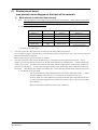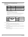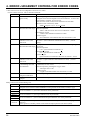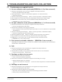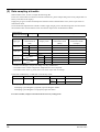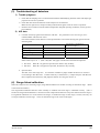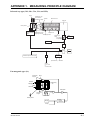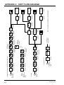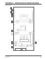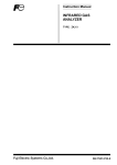
1
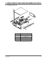
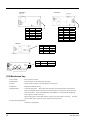
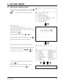
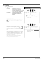
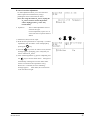
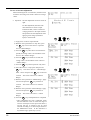
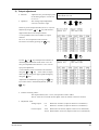
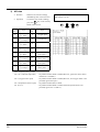
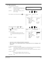
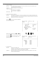
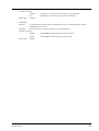
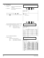
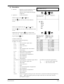
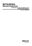
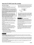
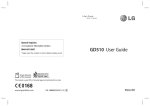
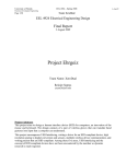
Service Manual
INFRARED GAS
ANALYZER
TYPE:
ZKJ-2
INZ-TN513328-E
PREFACE
This service manual describes the infrared gas analyzer (Type: ZKJ).
This service manual is intended for use with the instruction manual to help you in understanding maintenance and
inspection for the infrared gas analyzer (ZKJ). However, the basic operation of the analyzer is not covered in this
manual.
This manual provides information about the parameter settings in the factory mode, adjustment and precautions for
parts replacement, and troubleshooting for the infrared gas analyzer (ZKJ) which are not covered in the instruction
manual.
This service manual gives you useful hints to take immediate remedy for after-sales service.
• First read the instruction manual and service manual carefully until an adequate understanding is acquired,
and then proceed to installation, operation and maintenance of the gas analyzer. Wrong handling may
cause an accident or injury.
• The specifications of this analyzer will be changed without prior notice for further product improvement.
• Modification of this gas analyzer is strictly prohibited unless a written approval is obtained from the
manufacturer. Fuji Electric will not bear any responsibility for a trouble caused by such a modification.
Manufacturer:
Type:
Date of manufacture:
Product nationality:
Fuji Electric Instruments Co., Ltd.
Described in Fuji Electric’s company nameplate on main frame
Described in Fuji Electric's company nameplate on main frame
Japan
©Fuji Electric Instrument Co., Ltd. 2002
Issued in January, 2002
Request
• It is prohibited to transfer part or all of this manual without Fuji
Electric’s permission in written format.
• Description in this manual will be changed without prior notice
for further improvement.
INZ-TN513328-E
i
CONTENTS
PREFACE ..........................................................................................................................I
CONTENTS ..................................................................................................................... II
CAUTION ON SAFETY ................................................................................................III
1. STRUCTURE OF ANALYZER AND NAMES OF PARTS....................................1
(1) Analyzer main unit ......................................................................................................... 1
(2) Measuring element ......................................................................................................... 3
(3) Connection of parts ........................................................................................................ 5
2.
MAINTENANCE AND INSPECTION, AND REPAIR AND ADJUSTMENT AT
REPLACEMENT OF MEASURING UNITS ..................................................................7
(1)
(2)
(3)
(4)
(5)
(6)
(7)
Light source.................................................................................................................... 7
Sector motor and sector.................................................................................................. 8
Reference cell................................................................................................................. 8
Cell, cell window and O-ring ......................................................................................... 9
Detector (except for O2 sensor) ...................................................................................... 9
Built-in O2 sensor ......................................................................................................... 10
Printed circuit board ..................................................................................................... 11
1) Main printed circuit board (main board) ................................................................... 11
2) Amplifier printed circuit board (amplifier board) ..................................................... 12
3) Mother printed circuit board (mother board)............................................................. 13
4) I/O terminal printed circuit board (I/O terminal board) ............................................ 13
(8) Liquid crystal display (LCD) ....................................................................................... 13
(9) Power supply ................................................................................................................ 13
(10) Membrane key.............................................................................................................. 14
3.
FACTORY MODE ..................................................................................................15
(1) How to go to factory mode........................................................................................... 15
(2) Setting .......................................................................................................................... 16
1) O2 adjustment ............................................................................................................ 16
2) Output adjustment ..................................................................................................... 19
3) A/D data .................................................................................................................... 20
4) Other parameters ....................................................................................................... 21
5) Coefficient ................................................................................................................. 24
6) Calculation ................................................................................................................ 25
4.
5.
ERROR JUDGEMENT CRITERIA FOR ERROR CODES...................................26
TROUBLESHOOTING AND DATA COLLECTION ...........................................27
(1) Countermeasures against trouble.................................................................................. 27
(2) Data sampling at trouble .............................................................................................. 28
(3) Troubleshooting of detectors........................................................................................ 29
1) Trouble judgment ...................................................................................................... 29
2) A/D data .................................................................................................................... 29
(4) Range-linked calibration .............................................................................................. 29
APPENDIX 1. MEASURING PRINCIPLE DIAGRAM .......................................... A-1
APPENDIX 2. SOFT FLOW DIAGRAM................................................................. A-2
APPENDIX 3. PRINTED CIRCUIT BOARD PRAGRAM .....................................A-3
ii
INZ-TN513328-E
CAUTION ON SAFETY
First of all, read this “Caution on safety” carefully, and then use the analyzer in the correct way.
• The cautionary descriptions listed here contain important information about safety, so they should always
be observed. Those safety precautions are ranked in 2 levels, “DANGER” and “CAUTION”.
DANGER
Wrong handling may cause a dangerous situation, in which there is a risk of
death or heavy injury.
CAUTION
Wrong handling may invite a dangerous situation, in which there is a
possibility of medium-level trouble or slight injury or only physical damage
is predictable.
Caution on installation and transport of gas analyzer
DANGER
• This unit is not explosion-proof type. Do not use it in a place with
explosive gases to prevent explosion, fire or other serious accidents.
• This product must be installed in a place that meets the conditions
specified in the “instruction manual.”
Use of the analyzer in a place that does not meet the above conditions
may result in electric shocks, fire or malfunction.
CAUTION
INZ-TN513328-E
• During installation work, attention should be paid not to allow entrance
of wire fragments or other foreign matter into the product. Otherwise,
a fire, trouble or malfunction may be caused.
• When the gas analyzer needs to be lifted, be sure to put on protective
gloves. Don’t hold the analyzer with bare hands to prevent injury.
• Before transporting the analyzer, fix its casing so as not to open. If the
casing is separated and falls, injury may be caused.
• The gas analyzer is heavy. For carrying the analyzer manually, have at
least two persons conduct it with utmost care. If this caution is
ignored, body damage or injury may be caused.
iii
Caution on piping
In piping, the following precautions should be observed. Wrong piping
may cause gas leakage.
If the leaking gas contains a toxic component, there is a risk of serious
accident being induced.
Also, if combustible gas is contained, there is a danger of explosion, fire
or the like occurring.
DANGER
• Connect pipes correctly referring to the instruction manual.
• Exhaust should be led outdoors so that it will not remain in the locker
and installation room.
• Exhaust from the analyzer should be relieved in the atmospheric air in
order that an unnecessary pressure will not be applied to the analyzer.
Otherwise, any pipe in the analyzer may be disconnected to cause gas
leakage.
• For piping, use a pipe and a pressure reducing valve to which oil and
grease are not adhering. If such a material is adhering, a fire or the like
accident may be caused.
Caution on wiring
CAUTION
• The specified grounding construction is a requisite. Negligence of
grounding may cause electric shocks or malfunction.
• Be sure to use a power supply of correct rating. Connection of power
supply of incorrect rating may cause fire.
• Wiring work must be performed with the main power set to OFF to
prevent electric shocks.
• Wires should be the proper one meeting the ratings of this instrument. If
using a wire which cannot endure the ratings, a fire may occur.
Caution on use
iv
DANGER
• When handling standard gas such as calibration gas, read the instruction
manual for the standard gas for correct handling.
CAUTION
• Avoid continuous operation with the casing drawn out. Otherwise, the
casing may fall to cause injury.
• During operation, never touch the inside with the casing open, because
there is a danger of burns or electric shocks.
INZ-TN513328-E
Caution on maintenance and check
DANGER
• Before accessing the inside of analyzer with the casing open for
capillary replacement or the like purpose, be sure to turn off power
supply and purge not only the analyzer inside but also the measuring gas
line and auxiliary gas line adequately with the air or N2 gas. Also,
carefully prevent oil, etc. from sticking to the capillary, filter, packing
and the like parts. This is required for preventing poisoning, fire and
explosion due to gas leak, etc.
CAUTION
• Before starting the work, take off metallic parts such as wrist watch and
ring, and never touch the device with wet hands. Otherwise, electric
shocks may be caused.
• When the fuse is blown, detect its cause and use a new fuse of the same
type and capacity as those of the old one to prevent electric shocks or
other trouble.
Others
• If the cause of any fault cannot be determined despite reference to the
CAUTION
INZ-TN513328-E
instruction manual, be sure to contact your dealer or Fuji Electric’s
technician in charge of adjustment. If the instrument is disassembled
carelessly, you may have a shock hazard or injury.
• Don’t use replacement parts which are not specified by Fuji Electric.
Use of such parts will not only degrade performance but also result in an
accident or trouble.
• The old parts after replacement due to maintenance, etc. must be
disposed of as incombustible waste.
v
1. STRUCTURE OF ANALYZER AND NAMES OF PARTS
(1) Analyzer main unit
1
2
5
7
6
3
4
Parts No.
1
2, 4
3
5
6
7
INZ-TN513328-E
Part name
Top cover
Mounting screw
Slide rail
Input/output terminal
Input/output cable
Power supply cable
1
9
11
10
11
15
B
5
A
16
6
D
13
C
14
7
2
18
17
3
4
F
E
B
A
C
D
1
8
Parts No.
1
2
3
4
5, 6, 7
2
Part name
Decorative sheet (with built-in keys)
LCD panel
Fuse holder
Glass-tube fuse
Switching power supply
Parts No.
8
9
10
11
13
Part name
Gas inlet/outlet fittings
Main P.C.B
Mother P.C.B
Amplifier P.C.B
Built-in paramagnetic O2 sensor
INZ-TN513328-E
(2) Measuring element
For combination of 1 optical block with one sample cell
26
20
15
16
19
17 18
25
24
23
14
21
23
10
screw
11
6
1
22
24
9
21
23
13
2
4
12
26
25
3
24
8
23
26
21
22
7
5
Parts
No.
Part name
Parts
No.
Part name
Parts
No.
Part name
1
Sector motor
10
Cell window (for pipe cell)
18
O-ring 2 (for block cell)
2
Motor mounting plate
11
Reference cell
19
Cell window (for block cell)
3
Sector
12
Sample cell
20
Block cell
5
Infrared light source
13
Trimmer assembly
21
Measurement detector
6
Light source unit cover
14
Cell pushing
23
Light control plate
7
Photo-interrupter
15
Window pushing
24
Interference compensation detector
8
Distribution cell
16
O-ring 1 (for block cell)
25
Light shielding plate
9
O-ring (for pipe cell)
17
Washer
INZ-TN513328-E
3
For combination of 1 optical block with 2 sample cells
26
14
9
10
25
11
24
23
22
screw
21
12
21
13
1
6
2
4
20
8
26
3
5
4
7
INZ-TN513328-E
INZ-TN513328-E
blue
3
2
4
Noise filter
1
1a
2
2a
KEY SW
LCD
black
LDA10F-5
Power supply unit
LDA75F-18-Y(for optical block 1)
red
A
LED K
CN4
CN5
CN4
CN3
CN2
CN1
CN12
CN13
CN8
CN9
2nd component interference
compensation detector
2nd component
mesuring detector
1st component interference
compensation detector
1st component
mesuring detector
Amplifier board No. 1
Main board
Amplifier board No. 2
O2 sensor
CN3
4th component
mesuring detector
CN2
CN1
CN7
CN10
CN11
4th component interference
compensation detector
CN2 To main PC board
CN6
3rd component interference
compensation detector
3rd component
mesuring detector
Photo-interrupter
for optical block 1
CN6
Mother board
Light source
for optical block 2
Light source
for optical block 1
Motor
for optical block 2
Motor
for optical block 1
Motor driver
for optical block 2
Motor driver
for optical block 1
Note) The parts specified for optical block 2 and amplifier board No. 2 are not mounted
to the analyzer which does not have the second optical block.
The number of detectors varies with the number of gas components and
measurement range.
Photo-interrupter
for optical block 2
Power supply unit
LDA75F-18-Y(for optical block 2)
LDC30F-2
Power supply unit LDC60F-2
DISPLAY SW
brown
1
POWER SW
Fuse holder
Inlet
(3) Connection of parts
• Connection diagram
5
•
20
Piping diagram
O2 sensor
Infrared light
source side
Toaron φ6/φ3
Sample cell (1st optical block)
Toaron φ6/φ3
Yellow capillary L=20mm
Teflon φ6/φ4
INLET
CH1 CH2
Yellow capillary L=10mm(Toaron φ9/φ5 L=35)
OUTLET
INLET
CH3 CH4
OUTLET
Toaron φ9/φ5
Sample cell (2nd optical block)
Infrared light source side
"0" indicates a hose band.
For pipe joint, use Toaron φ9/φ6.
Block cell (2nd optical block)
This is a piping diagram of the analyzer without a purging line.
When the O2 meter and the second optical block are not provided,
pipes must be connected by bypassing them.
O2 sensor
Infrared light
source side
Toaron φ6/φ3
Sample cell (1st optical block)
Toaron φ6/φ3
Yellow capillary L=20mm
Teflon φ6/φ4
Toaron φ9/φ5
INLET
Toaron φ9/φ5
Yellow capillary L=10mm(Toaron φ9/5 L=35)
OUTLET
Toaron φ9/φ5
PURGE
Sample cell (2nd optical block)
Infrared light source side
"0" indicates a hose band.
For pipe joint, use Toaron f9/f6
Block cell (2nd optical block)
This is a piping diagram of the analyzer with a purging port.
When the O2 meter and the second optical block are not provided,
pipes must be connected by bypassing them.
6
INZ-TN513328-E
2. MAINTENANCE AND INSPECTION, AND REPAIR AND
ADJUSTMENT AT REPLACEMENT OF MEASURING UNITS
(1) Light source
• Recommended period of replacement : 5 years
1) Error mode
: Short circuit in and disconnection from the light source
electrically heated wire.
Phenomena
: Scale-out indication of analyzer.
Check
: Turn OFF the power of the analyzer and remove the
power cable connected to the light source. (Unplug
the CN8 and CN9 connectors on the mother board.)
Make sure a voltage of 19.8 ± 0.5 V is output between
pins 1 and 2 of CN8 or CN9 on the mother board.
Measure the resistance between the terminals of the
connector (having 2 pins) on the light source side.
Infrared light source
Resistance between
these terminals
The measured value is normally 20 Ω ± 2 Ω.
When the resistance value is infinite, cabling is
discontinuous.
As the resistance value decreases, the span narrows
(sensitivity is degraded).
To mother board
CN8 or CN9
2) Error mode
Phenomena
Check
: Sealed gas in light source leaks.
: Fluctuated indication
: If the analyzer output is drifted due to ambient conditions around the analyzer and other
units are normal except for the light source, sealed gas may leak.
3) Error mode
Phenomenon
: Separation of light source fixing spring
: Analyzer’s indication of measured value is unstable or surpasses the scale, and optical
balance cannot be adjusted.
: Remove the light source unit and check it visually.
Check
• Measures
: If the light source is found defective, replace the light source unit.
• Replacement
: Unplug connectors CN8 (for 1st optical block) and CN9 (for 2nd optical block) on the
mother board. Open the light source unit cover, remove the two screws which fasten the
light source and replace the light source unit with a normal one.
• Adjustment after replacement : Optical balance adjustment and zero/span calibration
TN512896-E
7
(2) Sector motor and sector
• Recommended period of replacement : 2 years (Sector motor)
1) Error mode
: Motor rotation stop
Phenomena
: Analyzer’s measured value surpasses the scale or indicated value does not change, and
ERROR-1 occurs.
Check :
With the analyzer powered on, remove the light source cover and make sure the sector is
rotating.
2) Error mode
: Unstable rotation or stop of a sector
Phenomena
: Scale-out indication of analyzer: Error- 1 occurs.
Indication is fluctuated.
Check :
With the analyzer power ON, check if unusual noise is generated from the motor due to
metal contact. (Sound at a constant high frequency is not abnormal.) If no noise is heard,
remove the light source unit cover. Turn ON the power of the analyzer and check the
rotation of motor shaft and sector
• Measures
: If the sector motor is defective, it must be replaced with a new one.
• Replacement
: Detach the light source unit cover. Unplug the connector which is connected from the
motor to the motor driver and pull the cable out of the cubicle through the grommet hole.
Remove four screws (M4) from the motor mounting plate which is fastened to the base of
light source unit, and the motor and sector can be pulled out. The sector can be separated
by removing the sector setscrew which fastens the sector to the motor shaft, and then the
motor can be separated by removing four screws from the motor mounting plate. Fasten a
replacement motor to the mounting plate and mount the motor by reversing the demounting
procedure. For mounting the motor, rotate the sector manually before fixing the motor
cover, and make sure the sector does not come in contact with the light source base, light
source, photo-interrupter, wires, etc. (frictional sound must not be emitted). Finally, fix
the light source unit cover.
• Adjustment after replacement:
Check of optical balance (adjust if significantly deviated) and calibration of zero/span
points
(3) Reference cell
• Recommended period of replacement: 5 years
Error mode
: Leakage of gas filled in cell
Phenomenon : Analyzer’s measured value is unstable (in particular, stability against change in ambient
temperature is degraded).
• Measures
: Replacement of reference cell
• Replacement
: Remove the reference cell and mount a new one.
• Adjustment after replacement:
Optical balance adjustment, moisture interference adjustment and zero/span calibration
8
INZ-TN513328-E
(4) Cell, cell window and O-ring
• Service life
: Usable unless contaminated or corroded.
• Recommended period of replacement : 2 years with O-ring
1) Error mode
: Contamination of cell, mixture of foreign matter, and contamination of cell window
Phenomena
: Scale-out indication, drift and calibration error occurred to analyzer
Check
: Disassemble the cell to assure that the inside is clean.
2) Error mode
: Crack in cell window
Phenomena
: No change in indication, slow response, calibration error, and indication fluctuation
Check
: Perform a visual check of the cell window.
• Measures
: Cell
: Clean the inside of the cell (refer to the instruction manual for details).
Replace If the inside is exposed to excessive contamination or corrosion.
Cell window : Clean the cell window. Replace if the inside is exposed to excessive
contamination.
• Adjustment after clean and replacement :
Check of optical balance (adjust if significantly deviated) and calibration of zero/span
points and response.
(5) Detector (except for O2 sensor)
• Recommended period of replacement : 5 years
1) Error mode
: Damage to mass-flow detector
Phenomena
: Scale-out indication of analyzer , calibration error
occurs.
Check
: Turn OFF the power of the analyzer and disconnect the
connector connected from the detector to PC board.
Measure each resistance between GND and S1 on the
PC board of detector and between GND and S2. The
measure values must be between 25Ω and 60Ω. If
the resistance value is beyond the specified range, the
detector element may be damaged.
Note) For resistance measurement, avoid
using a measuring device such as analog
tester that flows a current of 2 mA or
more. If used, the detection element
may be damaged.
2) Error mode
Phenomena
Check
• Measures
INZ-TN513328-E
Detector
S1
GND
S2
PC board
1 2 3 4
brown red white red
To amplifier board
: Sensitivity deterioration due to sealed gas leak
: Calibration error, fluctuation in indication and poor stability of analyzer’s measured value
: After making sure the light source is normal and the cell is clean, check moisture sensitivity.
(For the method of fault judgment and sensitivity check, refer to “5(3) Troubleshooting of
detectors” in “5. TROUBLESHOOTING AND DATA COLLECTION.”)
: Replace detector.
9
• Replacement
:
Turn off power supply to the analyzer, remove the bolts which fix the detector and remove
the detector. Mount a new detector and tighten the bolts.
The type of detector varies with the gas component to be measured. So before mounting,
check the symbol marked on the detector label.
• Adjustment after replacement :
Optical balance adjustment, moisture interference adjustment and zero/span calibration
○○○○○○○○
R1,2 =○○○
R3,4 =○○○
R* =○○○
A1
Detector type
(6) Built-in O2 sensor
• Recommended period of replacement : 10 years
• Error mode
: Breakage of O2 sensor
• Phenomenon
: Zero is read on the O2 meter and the reading remains unchanged even for the span gas.
• Check
: Confirmation of O2 input voltage --- Measure the voltage between check terminals TP4 and
SC on the main PC board using a digital voltmeter,
and make sure the voltage is about 0 V for zero gas
and 0.5 to 1 V for span gas. If the voltage does not
change between the zero and span gases, the O2 sensor
is damaged.
• Measures
: Replacement of O2 sensor
• Replacement
: Turn OFF the analyzer main unit
Unplug the O2 sensor connector. Then, remove the screws which fasten the O2 sensor
mounting plate to the main frame and separate the O2 sensor together with the mounting
plate. The O2 sensor is fixed by screws from the rear side of the mounting plate. So
remove the screws to detach the O2 sensor. A new sensor is mountable by reversing the
above procedure.
• Adjustment after replacement :
Zero and span calibration
10
INZ-TN513328-E
(7) Printed circuit board
(see printed circuit diagram at the back of the manual)
1)
Main printed circuit board (main board)
Note)
The main board is set according to the specifications of each analyzer. When placing an order for a
replacement PC board, notify the serial number of your analyzer in advance so that the new board
will have suitable parameters in it.
• Check
: Check of circuit voltage
Check terminal
GND1-Vcc
VG1-P15
VG1-N15
GND1-3.3V
GND2-TP10
Adjusting VR
VR4
Regulated voltage
+5±0.2V
+15±0.5V
-15±0.5V
+3.3±0.1V
About +26 V
Contents
Digital 5 V
Analog 15 V
Analog -15 V
Digital 3.3 V
LCD drive voltage,
contrast adjustment
• Precautions on replacement:
•
The cable (connector CN2) from LCD is connected to the main printed circuit board.
Do not unplug or plug the connector from or into the board with the analyzer power ON, or the electronic parts and
indication block may be damaged.
Before replacement, be sure to turn OFF the analyzer.
•
The cable (connector CN5) from the membrane key is connected to the main printed circuit board. Since a
stopper is provided on the CN5 connector, the flexible cable should not be pulled forcibly. Forcible pulling may
result in poor contact. For disconnecting the flexible cable, slide the stopper lightly toward you by holding both
sides of CN5 with fingers. And for reconnecting the flexible cable, insert it fully down to the bottom and attach
the stopper. (The flexible cable should be inserted with its contact face directed toward the printed circuit board.)
• Adjustment after replacement
The above-mentioned voltage check/adjustment and contrast adjustment (VR4). Contrast
should be adjusted so as to be easy to see indications at the height of your eyes.
In factory mode, zero offset adjustment, zirconia adjustment (when equipped with zirconia
O2 meter) and output adjustment (For adjustments in factory mode, refer to “factory mode”
in this manual.)
Moisture interference adjustment and zero/span calibration
INZ-TN513328-E
11
2)
Amplifier printed circuit board (amplifier board))
One board provided for each optical block (the following check items are
for one board)
• Check : Check of circuit voltage
Check terminal
Regulated voltage
Contents
a
b
SG-P15
SG-N15
+15±0.5V
-15±0.5V
c
N15-DV1
+17.5±0.5V
d
N15-DV2
+17.5±0.5V
e
SG-TP5
+2.5±0.1V
+15 V power supply
-15 V power supply
1st component detector power supply (used
in common for Main and Compo.)
2nd component detector power supply (used
in common for Main and Compo.)
Reference voltage for A/D conversion
Check of signal processing block:
Unplug all connectors of the cables from the detector.
Display the screen for “12. A/D Data” in Factory Mode.
In the A/D Data screen, numbers 0 to 3 stand for signals from the amplifier board for the 1st
optical block and numbers 4 to 7 stand for signals from the amplifier board for the 2nd
optical block.
Check if the count value in each number lies within a range of 15000 ± 1000.
Detector signal check (check by flowing the following gases)
Check
terminal
Under zero gas flow
Under span gas
flow
SG-TP1
1.0 to 2.0Vp-p
SG-TP2
-
Under 2°C-wet zero gas
TP1 and TP2 at almost
the same magnitude
ST-TP3
1.0 to 2.0Vp-p TP3 and TP4 at almost
8.33 Hz, 0.2 Vp-p max. in AC
the same magnitude
SG-TP4
signal width
* TP2 and TP4 signals are 0 V when the lower end of measuring range is 0 to 10% or more.
• Precautions on check:
The amplifier board is connected to the mother board by connector.
If the connector is not plugged in adequately, the above check may not bring about a normal
result. Before check, make sure the connector is plugged in correctly.
• Precautions on replacement:
A cable from the detector is connected to the amplifier board. If the connector is unplugged or
plugged in with the analyzer power ON, the detector may be damaged. Before replacement, be
sure to turn off the power supply.
• Adjustment after replacement:
Verification of the contents of the above checks, adjustment as per “4. Zero Offset” in Factory
Mode and zero/span calibration
12
INZ-TN513328-E
3)
Mother printed circuit board (mother board)
• Adjustment after replacement:
Output adjustment (Refer to “10. Output Adj.” in Factory Mode.)
4) I/O terminal printed circuit board (I/O terminal board)
• Adjustment after replacement :
Output check (Adjust if output is offset.
Refer to “10. Output Adj.” in Factory Mode.)
(8) Liquid crystal display (LCD)
• Service life of parts : 5 years
• Error mode
: Deterioration
• Phenomena
: LCD is not displayed, or the display is dim or flickers.
• Check
: Check LCD drive voltage on the main board.
Check connection to the main board.
(See “Check for printed circuit board”)
• Countermeasures against error : Replace LCD.
• Replacement
: Turn OFF the power. Disconnect the connector from the main printed circuit board and
replace it with a new one.
• Adjustment after replacement :
Check the drive voltage and adjust the contrast
(9) Power supply
• Recommended period of replacement : 5 years
• Error mode
: Power-down
• Phenomena
: No display and no output
• Check
: Check if short circuit occurs.
Disconnect the secondary SW power connector. Turn ON the power and check the
voltage at the connector. If no voltage is applied to it, replace.
• Measures
: Replace the S.W. power supply
• Replacement
: Turn OFF the instrument power.
replace it with a new one.
Disconnect the connector from the motherboard and
• Check after replacement :
Check the power supply voltage on the main printed circuit board.
INZ-TN513328-E
13
LDC30F-2
LDC60F-2
Name plate
Name plate
Input(N)
Output(L)
Pin
1
2
3
4
5
6
Symbol
V3
G2
G2
V2
G1
V1
Pin
1
2
3
4
5
6
7
8
Voltage
–15V
+15V
+5V
Symbol
V3
G2
G2
V2
G1
G1
V1
V1
Voltage
–15V
+15V
+5V
+5V
LDA10F
Pin
1
2
3
4
Output (+)
Output (–)
Symbol
–V
–V
+V
+V
Voltage
+5V
+5V
Name plate
CN1
FG
Input(N)
Input(L)
Name plate
Output(-)
Output(+)
Pin
1 to 3
4 to 6
Symbol
–V
+V
Voltage
+19.8V
CN2
Output voltage variable resistor
(10) Membrane key
• Error mode
: Key contacts are worn.
• Phenomena
: It prevents the switch from being operated.
• Check
: Check for the contacts with main printed circuit board
• Measures
: Replace the membrane key.
• Replacement
: Turn OFF the power. Disconnect the connector from the main print circuit board.
Remove soldered portion of the power switch and remove the power switch from the
main instrument. Strip off membrane key and adhesives are wiped off completely.
Then, replace it with a new one.
Remove the power switch and install it in the reverse procedure as removal. Connect
the key cable to the connector of the main print circuit board.
• Check after replacement :
Check key-in operation.
14
INZ-TN513328-E
3. FACTORY MODE
(1) How to go to factory mode
Point the cursor to “8. To Factory Mode” by using the
or
key on the Maintenance Mode screen and enter the
ENT key.
Then, the password input screen appears.
ENT
Enter the password.
To select setting items, set “4 0 4 3”.
(“8. O2 Adj.,” “10. Output Adj.” and “13. Others.” are
settable with “4043.” Items 1, 2, 3, 5, 6, 7, 9, 12, 13, 14, 15,
16 and 17 can be viewed.)
key.
Select digits by the
Change numerical values by using
or
key.
After password entry has been completed, press the ENT
key, and the Factory Mode initial screen appears
ENT
How to select setting item from Factory Mode screen
On the Factory Mode screen that appears, point the cursor
key.
or
,
to the item you want by using the
To get access to each setting screen, press the ENT key.
To return from each setting screen to the initial screen,
press the -5+ key.
-5+
-5+
When escaping from the Factory Mode screen to the
Maintenance Mode screen, press the -5+ key.
INZ-TN513328-E
Into each parameter screen
15
(2) Setting
1) O2 adjustment
• Function
• Operation
: Paramagnetic, External O2 or
Zirconia sensor is selectable.
Necessary adjustment can be carried
out for each oxygen measurement.
Factory mode initial screen
The cursor is in 8
ENT
-5+
ENT
-5+
: The setting screen where O2
adjustment is performed is as
follows.
Selection of O2 sensor
Match the cursor with Selection of O2 and press the
ENT key.
Indication of this setting item will be
inverted
Setting item can be changed by pressing
and
keys and its selection can be determined by the ENT
key.
When “Paramagnetic” and “External O2” are selected,
“O2 offset” is displayed in the setting item. When
“Zirconia” is selected, “Zirconia adjustment screen” is
displayed in the setting item.
After “Selection of O2,” O2 offset adjustment or
zirconia adjustment can be carried out.
16
INZ-TN513328-E
In case of O2 offset adjustment
O2 offset adjustment allows you to store electrical
offset required for measurement by using a
paramagnetic sensor and external O2 meter.
(Note) For using the built-in O2 sensor, unplug the
O2 sensor connector before adjustment.
Unless unplugged, the O2 sensor may
become faulty.
• Operation
: The O2 offset adjustment screen is
shown at the right.
For this adjustment, input 0 V to or
shot-circuit the O2 input terminal of
ZKJ-2.
1) Add 0 mV (short) to the O2 input.
2) With the cursor placed next to “Input Adj.” (O2 offset
adjustment), the “O2 Offset” screen is displayed by
ENT
ENT
pressing the ENT key.
3) Press the ENT key on the “O2 offset” screen, and the
message appears, prompting you to verify that you
want to offset the O2 sensor.
4) After confirming that the O2 input is completed, press
the ENT key to save the offset values.
Each gain is
automatically exchanged to save the offset values.
About 15 seconds will be required for saving.
When “Go” is selected, the “Now offsetting”
message appears.
After offset, the screen returns
to the one shown in right.
INZ-TN513328-E
17
In case of zirconia adjustment
When measuring the O2 concentration, the data can be
stored for converting A/D counter values into voltage
values.
• Operation : Zirconia adjustment screen is shown at
right.
For this adjustment, disconnect the
cable from the O2 sensor to input
terminal of ZKJ, connect a reference
voltage generator to the input terminal
and perform zirconia adjustment while
applying each voltage (simulative
input) to the terminal.
ENT
-5+
ENT
-5+
1) Apply 0 mV to the O2 input terminal.
2) With the cursor placed next to Adj. Zero, press
the ENT key to move the cursor to a position
next to “100mV Range”.
3) Press the ENT key after about 10 seconds have
passed, the voltage value is saved and the cursor
moves to the “250mV Range”.
4) Press the ENT key in about 10 seconds, the
voltage value is saved and the cursor returns to
“100mV Range”.
5) Press the -5+ key and escape from “Adj. Zero”.
6) Move the cursor to “Adj. Span” and press the
ENT key.
The cursor move to “–50mV Range”.
Enter –50 mV and press the ENT key in about 10
seconds. The cursor will move to “100mV
Range”.
7) With the cursor placed on “100mV Range”, apply
100 mV and press the ENT key in about 10
seconds. The cursor will move to “250mV
Range”.
8) With the cursor placed to “250mV Range”, apply
250 mV and press the ENT key in about 10
seconds.
Range”.
The cursor will return to “–50mV
9) Press the -5+ key, and adjustment is completed.
* After adjustment has been completed, check
that the indication value is within the range of
±0.2 mV with respect to the input value when 0,
50 and 150 mV is applied to the O2 input
terminal according to “1. Sensor Input Value” in
the Maintenance mode. If the indication is
beyond the range, repeat steps 1) to 9).
18
INZ-TN513328-E
2) Output adjustment
• Function
: Adjust the zero point and span point
of the analog output to 4 to 20 mA
or 0 to 1 V.
• Operation
: The Analog Output Adjustment
screen is as shown in right.
Factory mode initial screen
The cursor is in 10
ENT
-5+
ENT
-5+
Select any of the output terminals (OUT 1 to 12) to be
key and connect a
or
adjusted by using the
digital multi-meter to the output terminal.
* Correspondence of the OUT number to output
terminal
OUT 1 to 12 corresponds to CH1 to CH12.
Set value is inverted by pressing the ENT key.
Use the
or
key and adjust the indication so
that the digital multi-meter reads 4 mA or 0 V for
zero-point adjustment and 20 mA or 1 V in case of
span-point adjustment.
* The indication can be increased or decreased by
key. If the values are larger
or
using the
than expected, change the upper-significant digit by
key.
using the
Adjustment is established by pressing the ENT key.
If you don’t want to establish adjustment, press the
-5+ key.
• Contents of setting values :
The output number (OUT 1 to 12) corresponds to CH1 to CH12.
The set values are converted into the digital values to transfer to the D/A converter.
• Adjustment value:
Voltage output:
Current output:
0V
Within 0V ±0.002 V (Adjust so that error is minimized.)
1V
Within 1V ±0.002 V (Adjust so that error is minimized.)
4 mA
Within 4mA ±0.05 mA (Adjust so that error is minimized.)
20 mA Within 20mA ±0.05 mA (Adjust so that error is minimized.)
INZ-TN513328-E
19
3) A/D data
• Function
• Operation
: Measures the counter readings
immediately after A/D conversion.
: To measure the counter readings,
Factory mode initial screen
The cursor is in 12
press the ENT key on the “Factory
ENT
Mode” initial screen.
Ainp
No.
0
1
2
3
4
5
6
7
Type
Optical block
1-1, Main
Optical block
1-1, Compo.
Optical block
1-2, Main
Optical block
1-2, Compo.
Optical block
2-1, Main Optical block
2-1, Compo.
Optical block
2-2, Main
Optical block
2-2, Compo.
Ainp
No.
Type
8
Oxygen input
9
Temperature
10
-
11
-
12
13
14
15
-5+
Optical block 1
motor pulse +
Optical block 1
motor pulse Optical block 2
motor pulse +
Optical block 2
motor pulse -
When supplying zero gas (dry);
No. 0 to 7 (infrared component)
: No problem within 10000 to 22000 (However, ignore the values where
no detector is available.)
No. 8 (oxygen sensor input)
: No problem within 10000 to 18000 (However, if an oxygen meter is not
provided, ignore this input.)
No. 9 (temperature sensor input) : No problem within 5000 to 18000.
No. 12 to 15
: No problem within 58000 to 61000 (If the 2nd optical block is not
provided, ignore Nos. 14 and 15.)
20
INZ-TN513328-E
4) Other parameters
• Selection of minus indication:
Function
: Minus-side indication (below zero) of
measured concentration values can be
selected or avoided.
Operation : Minus indication selecting screen is
shown at right.
Factory mode initial screen
The cursor is in 13
ENT
-5+
ENT
-5+
Invert indication of the setting item by the ENT key.
Select Disappear/Appear by
and
keys.
Press the ENT key for determining your setting, or
the -5+ key for avoiding it.
Contents of setting:
Yes; Indicates and outputs the minus side.
No: Avoids indication and output of the minus
side.
Initial value : Disappear
*
This mode is used for checking the indication in adjustment.
When “Appear” is set for Minus Indication prior to adjustment, be sure to set “Disappear” after
adjustment.
• Calibration concentration zero variable
Function
: Turn ON this setting when calibration to a value other than 0 is desired in zero calibration,
and a calibration concentration at zero point will become settable.
Operation : Invert the relevant setting as in the selection of minus indication and select ON or OFF as
desired.
Contents of setting :
OFF; Fixes the calibration value at zero point to 0.
ON; Makes the calibration value at zero point variable.
Initial value : OFF
INZ-TN513328-E
21
• Error 10 judgment
Function
: It is settable whether to judge an error (Error 10) which occurs if the connection to the
input/output terminal is abnormal.
Operation : ON/OFF selection as in the above item
Contents of setting:
ON; Selects Error 10 judgment.
OFF; Avoids Error 10 judgment.
Initial value : ON
• Range link calibration coefficient
Function
: The calibration coefficient to be used for calibration can be checked and initialized when
range-linked calibration is set in user-mode calibration setting and calibration range action.
Operation : Operation and screen are described below.
Press the -5+ key for entry into the coefficient
check and clearing screen.
Select a gas component by the
and
keys.
ENT
-5+
Pressing the ENT key clears the factor to 1.0000.
Pressing the -5+ key returns display to the
previous screen.
• Zero gas action
Function
: The gas to be used for zero
calibration is selectable between cylinder gas and atmospheric air. In calibration, the
calibration contact according to your selection is operated.
Operation : While the indication of the relevant setting is inverted, select Cylinder or Air as in the
selection of minus indication.
22
INZ-TN513328-E
Contents of setting:
Cylinder
Air
Initial value : Cylinder
; Cylinder air or N2 gas is used as the gas for zero calibration.
; Atmospheric air is used as the gas for zero calibration.
• MODBUS
Function
: In communication with the serial communication port, it is settable whether to use the
MODBUS protocol or not.
Operation : Simple selection of Used or Unused status as described above
Contents of setting:
Disable
; The MODBUS communication protocol is unused.
Enable
; The MODBUS communication protocol is used.
Initial value : Disable
INZ-TN513328-E
23
5) Coefficient
• Function
:
• Operation :
Displays zero offset and calibration
coefficient.
The coefficient initial screen is as
shown at right.
Select any item by using the
or
Factory mode initial screen
The cursor is in 16
ENT
-5+
ENT
-5+
key.
Press the ENT key, and each display screen appears.
In case of moisture interference or offset selection:
• Display contents: Displayed for each CH
Offset ・・・・ Offsets detector or O2 sensor.
H2O ・・・・・ Moisture interference
compensation coefficient
In case of selection of moisture
interference or offset
In case of calibration coefficient:
• Display contents:
Displayed in range of each CH
Zero ・・・・・ Zero calibration coefficient
Span ・・・・・ Span calibration coefficient
24
In case of selection of calibration
coefficient
INZ-TN513328-E
6) Calculation
• Function
• Operation
: Displays a screen in which the values
under the internal calculation of
analyzer can be checked for each gas
component.
Factory mode initial screen
The cursor is in 17
ENT
-5+
ENT
-5+
: As described below.
Select an item by the
and
keys.
Press the ENT key for entry into each indication
screen.
Select a gas component by the
and
keys.
Press the ENT key for entry into the calculation check
screen.
When further pressing the ENT key, change of the
values will stop.
The previous status can be restored
by pressing the -5+ key.
Contents of indication
(In selection of infrared component)
(X: Main, Y: Compo.)
X, Y
= A/D conversion input values
X, Y1
= After offset
X, Y2
= Scale conversion
X, Y3
= Filter
X, Y4
= Zero calibration (for each of Main
and Compo.)
X, Y5
= Span temperature compensation
X6
= Interference compensation
X7
= Zero temperature compensation
X8
= Zero calibration
X9
= Span calibration
X10
= Linearization
(In selection of zirconia oxygen meter)
(In selection of paramagnetic or external oxygen meter)
X
= A/D conversion input value
X
= A/D conversion input value
X1
= mV conversion value
X1
= After offset
X2
= Scale conversion
X3
= Filter
X4
= Zero point temperature compensation
X5
= Zero calibration
X6
= Span temperature compensation
X7
= Span calibration
X8
= Linearization
Action : When pressing the zero key, the zero valve turns on, and it turns off when pressing the key
again.
When pressing the span key, the span valve turns on, and it turns off when
pressing the key again.
INZ-TN513328-E
25
4. ERROR JUDGEMENT CRITERIA FOR ERROR CODES
* This section covers the error judgement criteria for error codes.
For the contents of errors, refer to Instruction Manual.
Error No.
Contents
Criteria
Error 1
Motor rotation detector
Detector signals generated due to motor chopping are converted into
signal is faulty.
rectangular waves and rectangular waves are monitored. If waves are
not generated or irregular, an error occurs.
A/D conversion value (count) can be checked on the A/D data
indication screen in the factory mode.
59000 < Ainp No. 12, 13, 14, 15 < 61000
Error 4
Zero calibration is not
If the following ranges are not met in zero calibration, an error occurs.
within the allowable range Infrared component:
5000 ≤ A/D conversion value in zero calibration ≤ 25000
Paramagnetic oxygen:
-3000 ≤ zero calibration coefficient ≤ 3000
Zirconia oxygen:
Zero calibration concentration after mV conversion ± 5 mV
Error 5
An amount of zero
This error occurs in the following condition.
calibration is over 50%
50% of FS < (Zero calibration concentration set value) – (current
of full scale.
display)
Error 6
Span calibration is not
When span calibration coefficient is not within the following range,
within the allowable range. error occurs.
Infrared component:
0.05 < span calibration coefficient < 5
Paramagnetic oxygen:
0.5 < span calibration coefficient < 16
Zirconia oxygen:
Span calibration concentration after mV conversion ± 10 mV
Error 7
An amount of span
This error occurs in the following condition.
calibration is over 50%
50% of FS < (Span calibration concentration set value) – (current
of full scale.
display)
Error 8
Measured values fluctuate If A/D conversion value fluctuates beyond each range specified below
to much during zero and in calibration, an error occurs.
span calibration
Infrared component, paramagnetic oxygen meter:
A/D input value ± 100
Zirconia oxygen:
Oxygen concentration after mV conversion ± 0.2 mV
Error 9
Calibration is abnormal
Error corresponding to No. 4 to No.7 occurs during auto calibration
during auto calibration
Error 10 Output cable connection is Error occurs if no response is made from the output IC
improper.
Main portions to be checked during error
Error No.
Error 1
Error 4
Error 5
Error 6
Error 7
Error 8
Error 9
Error 10
26
Main portions to be checked
Sector motor rotation, mother and amplifier printed circuit board synchronization signal,
rectangular waves between GND and MPD3 on main printed circuit board (8.33 Hz, 5 Vp-p)
See service manual “5. (1) No zero calibration can be performed”.
See service manual “5. (1) No span calibration can be performed”.
See service manual “5. (1) Zero calibration and span calibration can not be performed”.
Contact portions of main printed circuit board and motherboard printed circuit board (plug-in
connector).
Contact portions of mother printed circuit board and output printed circuit board (cable).
INZ-TN513328-E
5. TROUBLESHOOTING AND DATA COLLECTION
(1) Countermeasures against trouble
1) No zero calibration can be performed (ERROR No. 4, 5 or 8 has occurred.)
1) Check that a specified flow rate of zero gas is supplied to the analyzer main unit
⇒ Locate a gas leaked portion and remedy.
2) Check optical balance. (Refer to “optical balance adjustment” in instruction manual.)
⇒ Adjust optical balance.
3) Check the A/D data against the display. (Refer to “Sensor Input Value” in Maintenance Mode.)
4) If this trouble has occurred on the zirconia O2 measurement, check the sensor output voltage.
5) If ERROR No. 5 has occurred, carry out zero calibration forcibly and check the result.
⇒ If ERROR No. 4 occurs, return to above.
2) No span calibration can be performed (ERROR No. 6, 7 or 8 has occurred.)
1) Check that specified flow rate of span gas is supplied to the analyzer main unit.
⇒ Locate a gas leaked portion and remedy.
2) Check that zero calibration can be properly performed.
⇒ If zero calibration cannot be performed, repeat the procedure in “No zero calibration can be performed”
described above.
3) Check the A/D data against the display. (Refer to “Sensor Input Value” in Maintenance Mode.)
⇒ Check for change from when flowing the zero gas.
4) Check the amplifier PC board. (Refer to “amplifier printed circuit board” in this manual.)
5) If this trouble has occurred on the zirconia O2 meter, check the sensor output voltage.
6) If ERROR No. 7 has occurred, carry out span calibration forcibly and check the result.
⇒ If ERROR No. 6 occurs, return to above.
3) Error occurs in automatic calibration.
(ERROR No. 9 has occurred.)
Depending on whether the error has occurred in zero calibration or span calibration, the relevant measure
described above should be taken.
4) Drift
1) Check that specified flow rate of measured gas is supplied to the analyzer main unit.
⇒ Locate a gas leaked portion and remedy.
2) Check that the cell window, O-ring, detector window and cell inside are not contaminated.
⇒ Clean the cell and window.
Replace parts.
5) Readings are high or low too much.
1) Check for influence by moisture interference.
⇒ Carry out moisture interference adjustment.
2) Check if the concentration of interference component in measured gas is too high.
⇒ Moisture should be below 2°C saturation.
Check for other interference components.
gas.)
(Ask the user what components are contained in measured
6) Readings are not increased
1) Check that specified flow rate of measured gases are supplied to the analyzer main unit.
⇒ Locate a gas leaked portion and remedy.
2) Check that zero and span calibration can be performed.
⇒ If possible, check for sampling system (related to measured gas) and take remedies.
⇒ If not possible, check the item 1) and 2).
INZ-TN513328-E
27
(2) Data sampling at trouble
When trouble occurs, be sure to sample the following data.
In the case of the trouble in connection with the characteristic, please sample data (please surely sample data to a
factory at the time of an inquiry).
Supply the gas given in Table and sample the measured value of measurement screen, sensor input values in
maintenance mode.
On the measured component that caused a trouble, supply the gas given in the following table, and write down
the measured value of measurement screen and “Sensor Input Value” in Maintenance Mode.
Measurement
component and range
Supply gas
Zero gas
Span gas
2°C-wet
zero gas
Sample gas
Component
Calibration
concentration set
value
Range 1
Measurement
display value
Range 2
Sensor input value in
maintenance mode
(Main)
Sensor input value in
maintenance mode
(Compo.)
Range 1
Range 2
Range 1
Range 2
Range 1
Range 2
Range 1
Range 2
• If there is no Range 2, the part of a Range 2 is entry needlessness.
• If trouble occurs to other components, sample data for each component.
• If trouble occurs on the O2 meter, there is no sensor input value for Compo.
Check each coefficient by “Coefficient” in the factory mode.
Channel No.
Offset
Moisture interference
Zero coefficient
Range 1
CH1
Span coefficient
Range 2
• Sampling system diagram
If sampling system diagram is prepared, report the diagram number.
If sampling system diagram is not prepared, report the sketch.
For other troubles, sample various data about necessary setting items.
28
INZ-TN513328-E
(3) Troubleshooting of detectors
1) Trouble judgment
a. Check that the sampling line is not abnormal and that the dehumidifying line/filter status and sample gas
properties do not have a problem.
b. Check that other units and functions of the analyzer are not abnormal.
Make sure the light source, sample cell and synchronization signal circuit do not have a problem.
c. Examine each correlation with the ambient temperature and plant operating conditions (such as gas and
heat radiation).
2) A/D data
a. Calculate sensitivity against steam from the A/D data. For generation of 2°C-wet zero gas, use a
reliable bubbler and electronic cooler.
Check the A/D data of each detector on the optical balance screen when flowing each gas listed in the
following table.
Measurement detector (Main) Interference compensation
detector (Compo.)
Dry zero gas
Zm
Zc
Dry span gas
Sm
Sc
Wm
Wc
2°C-wet zero gas
Span gas concentration
(ppm)
P
-
Steam sensitivity H = P × (Wm - Zm)/(Sm - Zm) ppm, concentration of measured component
•
SO2 meter
When H > 70 ppm SO2 equivalent, the detector may be faulty.
•
NO meter
When H > 180 ppm NO equivalent, the detector may be faulty.
b. Span A/D data
This data varies with range ratio. It is therefore unreliable to judge whether the detector is normal or
not according to this data alone. If steam sensitivity is abnormal in 1), compare the span A/D data with
that at shipment from the factory and judge the detector also using the result in 1).
(4) Range-linked calibration
When this analyzer has 2 measuring ranges, range-linked calibration is settable in setting of calibration range. (Refer
to the instruction manual.)
The range-linked calibration function works normally on condition that each range is calibrated correctly. (This is
because the range-linked calibration is carried out so that compensation amount is always the same between the ranges.)
If a significant indication error occurs between the ranges, set calibration range in each range (“current”) and carry out
zero/span calibration in each range. Then, set calibration range to the “both” mode again.
INZ-TN513328-E
29
APPENDIX 1. MEASURING PRINCIPLE DIAGRAM
Infrared ray type (NO, SO2, CO2, CO, and CH4)
Motor
Distribution cell
(also used as
Trimmer
interference filter)
Reference cell
Detector
Rotary sector
Sector
Sample cell
synchronization Infrared light source
(single light source)
signal
Sample gas inlet
Sample gas
outlet
Gain
changeover
AC voltage
amplification
O2 meter
(Option)
A/D
CPU
External input/contact output
RAM
ROM
Indication
block
D/A
Operation key
Indication
Output
0 to 1 V DC
or
4 to 20 mA DC
Paramagnetic type (O2)
Permanent
magnet
Mirror
Gas inlet
Measuring
cell
Magnetic field
Gas outlet
Preamplifier
Permanent
magnet
Photo diode
Emitting diode
Display
Signal
process
calculation
Output
INZ-TN513328-E
A-1
A-2
Detector input
signal
O2 meter
Compo.
detector input
signal
Main detector
input signal
+÷
A/D
converter
Temperature
sensor input
signal
±
×
A/D
converter
×
Span
temperature
calibration
×
±
Digital filter
+÷
Linearization
Span
Linearization
temperature
compensation
×
Zero point
calibration
Zero point
calibration
Temperature sensor
Digital filter
±
±
±
*
A/O
calculation
To temperature
compensation
Interference
compensation
coefficient
Zero point
Zero point
temperature calibration
compensation
Interference
compensation
Zero point Span
calibration temperature
compensation
±
Digital filter
+÷
+÷
A/D
Offset
converter adjustment
±
A/D
Offset
Digital filter
converter adjustment
±
Infrared ray component (for each gas component)
Moving
average
A/O
calculation
A/O
calculation
A/O
calculation
Instantaneous
value
0 to1V DC
or 4 to 20mA
Indication
Moving average
value
0 to1V DC
or 4 to 20mA
Indication
Instantaneous
value
0 to1V DC
or 4 to 20mA
Indication
Note 1) Asterisk (*) indicates an output holding point.
Indication
Instantaneous
value
*
+÷
Linearization
0 to1V DC
or 4 to20 mA
O2 conversion
calculation
Span point
calibration
×
APPENDIX 2. SOFT FLOW DIAGRAM
INZ-TN513328-E
INZ-TN513328-E
CN1
CN2
CN2
CN5
GND2
TP10
TP10
TK369163R0 Japan
GND2
VR4
VR4
GND1
GND1
Vcc
3.3V
Vcc 3.3V
VG1
N15
N15
VG1
P15
P15
APPENDIX 3. PRINTED CIRCUIT BOARD DIAGRAM
Main PC board
A-3
Amplifier PC board
TP4
TP3
DV2
DV2
TP4
DV1
DV1
TP2
TP1
TP2 TP1
TP3
T15
N15
SG
P15
N15
SG
TK365874R1
Japan
A-4
INZ-TN513328-E