1
HES Series Service Manual
i
TABLE OF CONTENTS
Table Of Contents
Models HES-20, HES-30 & HES-40
Page No.
1. INTRODUCTION
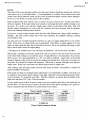
A Brief History of Our Company ................................................................................................................ 1-1
Vogt Energy-Saving Tube-Ice® Machines................................................................................................... 1-1
Preview
.................................................................................................................................................... 1-1
Important Safety Notice............................................................................................................................... 1-2
Special precautions to be observed when charging refrigeration systems ................................................... 1-2
Safety Symbols & What They Mean ........................................................................................................... 1-3
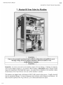
2. RECEIPT OF YOUR TUBE-ICE® MACHINE
Inspection ................................................................................................................................................... 2-1
Safety Valves............................................................................................................................................... 2-2
Machine Room ............................................................................................................................................ 2-2
Storage
.................................................................................................................................................... 2-2
3. HOW YOUR TUBE-ICE® MACHINE WORKS
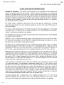
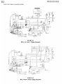
Principle of Operation ................................................................................................................................. 3-1
Air Cooled Piping Diagram, FIGURE 3-1 .................................................................................................. 3-2
Water Cooled Piping Diagram, FIGURE 3-2.............................................................................................. 3-2
Piping Schematic Nomenclature.................................................................................................................. 3-3
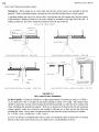
How Ice Is Stored
Bin Control Sensor Installation, FIGURE 3-3............................................................................................. 3-4
Storing Ice ................................................................................................................................................... 3-4
Ice Bin Capacity .......................................................................................................................................... 3-4
When Ice Bin Thermostats Are Not Used ................................................................................................... 3-5
Single Ice .................................................................................................................................................... 3-5
Dual Ice .................................................................................................................................................... 3-5
Crushed Ice Preferred .................................................................................................................................. 3-5
4. ELECTRICAL CONTROLS & THEIR FUNCTIONS
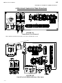
Control Panel, FIGURE 4-1A ..................................................................................................................... 4-1
Control Panel with Hoffman Enclosure, FIGURE 4-1B.............................................................................. 4-1
Control Panel Part Numbers, TABLE 4-1 ................................................................................................... 4-2
Description of Control Panel Parts .............................................................................................................. 4-3
Wiring and Electrical Connections, FIGURE 4-2 ....................................................................................... 4-5
Electrical Specifications, TABLE 4-2 ......................................................................................................... 4-5
5/24/11
ii
HE S Series Service Manual
TABLE OF CONTENT
Page No.
4. ELECTRICAL CONTROLS & THEIR FUNCTIONS (Cont.)
PLC Features & Functions........................................................................................................................... 4-6
PLC Display, FIGURE 4-3.......................................................................................................................... 4-6
PLC Inputs & Outputs, TABLE 4-3 ..................................................................................................... 4-6
PLC Start-Up Mode ............................................................................................................................. 4-7
PLC Stand-By Mode ............................................................................................................................ 4-7
PLC Freeze Mode ................................................................................................................................ 4-7
PLC Harvest Mode............................................................................................................................... 4-7
PLC Partial Pump-Down Mode............................................................................................................ 4-7
PLC Partial Pump-Down Time, TABLE 4-4........................................................................................ 4-7
PLC Total Pump-Down Mode.............................................................................................................. 4-7
PLC Clean Mode.................................................................................................................................. 4-8
PLC Fault Mode ................................................................................................................................... 4-8
PLC Fault Codes, TABLE 4-5 ............................................................................................................. 4-8
Copeland Performance Alert ....................................................................................................................... 4-9
Copeland Performance Alert wiring, FIGURE 4-4 ..................................................................................... 4-9
Copeland Performance Alert Codes & Lockout Configuration, TABLE 4-6 .............................................. 4-9
Machine Fault Startup Sequence, FIGURE 4-5........................................................................................... 4-10
Fault Indicator / Selector Switch Location, FIGURE 4-6............................................................................ 4-10
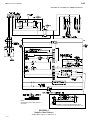
Dual Ice Machine (200V/208-230V) Wiring Schematic, FIGURE 4-7 ...................................................... 4-11
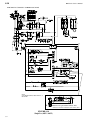
Single Ice Machine (200V/208-230V) Wiring Schematic, FIGURE 4-8 .................................................... 4-12
Single Ice Machine (Dual voltage -50hz) Wiring Schematic, FIGURE 4-9 ................................................ 4-13
Single Ice Machine (400V/460V) Wiring Schematic, FIGURE 4-10 ......................................................... 4-14
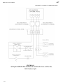
Air Cooled Condenser Wiring Schematic (Single Fan – 50/50 Split), FIGURE 4-11................................. 4-15
Air Cooled Condenser Wiring Schematic (Single Fan – 50/25/25 Split), FIGURE 4-12............................ 4-16
Air Cooled Condenser Wiring Schematic (Dual Fan – 50/50 Split), FIGURE 4-13 ................................... 4-17
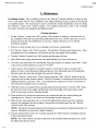
5. MAINTENANCE
Ice-making Section ...................................................................................................................................... 5-1
Cleaning Procedure ..................................................................................................................................... 5-1
Sanitizing Procedure.................................................................................................................................... 5-2
Water Distributors, FIGURE 5-1................................................................................................................. 5-4
Water Distributors, Freezer Cover, Gasket Part #'s, TABLE 5-1 ................................................................ 5-4
Water Tank.................................................................................................................................................. 5-5
Drip Pan .................................................................................................................................................... 5-5
Water Cooled Condensers ........................................................................................................................... 5-5
Draining the Condenser ............................................................................................................................... 5-6
Chemical Cleaning the Condenser............................................................................................................... 5-6
5/24/11
HES Series Service Manual
iii
TABLE OF CONTENTS
Page No.
5. MAINTENANCE (Cont.)
Mechanical Cleaning the Condenser ........................................................................................................... 5-6
Part I..................................................................................................................................................... 5-6
Part II ................................................................................................................................................... 5-7
Replacement Gaskets, TABLE 5 -2............................................................................................................. 5-7
Air-Cooled Condenser Cleaning.................................................................................................................. 5-8
Compressor Oil............................................................................................................................................ 5-8
Cutter Gear Reducer Oil.............................................................................................................................. 5-8
Preventive Maintenance .............................................................................................................................. 5-9
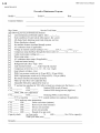
Daily Checklist ............................................................................................................................................ 5-9
Note To Manager or Owner ........................................................................................................................ 5-9
Preventive Maintenance Program................................................................................................................ 5-10
6. TROUBLESHOOTING
Machine Faults ............................................................................................................................................ 6-1
PLC Fault Codes, TABLE 6-1 .................................................................................................................... 6-1
Machine Fault Indicator Light, FIGURE 6-1 .............................................................................................. 6-2
Machine Fault Startup Sequence, FIGURE 6-2........................................................................................... 6-2
PLC, FIGURE 6-3 ....................................................................................................................................... 6-3
PLC Inputs and Outputs, TABLE 6-2 ......................................................................................................... 6-3
Machine Will Not Run ................................................................................................................................ 6-4
Checking PLC ............................................................................................................................................. 6-4
Low Ice Capacity......................................................................................................................................... 6-5
Fault # 1, High/Low Pressure during Freeze ............................................................................................... 6-6
Fault # 2, High/Low Pressure during Harvest.............................................................................................. 6-7
Fault # 3, High/Low Pressure during Partial Pumpdown............................................................................. 6-7
Fault # 4, High/Low Pressure during Total Pumpdown .............................................................................. 6-8
Fault # 5, Short Cycle Fault......................................................................................................................... 6-9
Fault # 6, Long Cycle Fault ......................................................................................................................... 6-9
Fault # 7, Pump Motor Overload Fault........................................................................................................ 6-10
Fault # 8, Cutter Motor Overload Fault ....................................................................................................... 6-10
7. SERVICE OPERATIONS
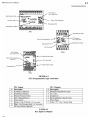
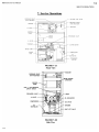
Machine Component Layout (Front View), FIGURE 7-1A ........................................................................ 7-1
Machine Component Layout (Side View), FIGURE 7-1B .......................................................................... 7-1
Machine Component Layout (Rear View - WC), FIGURE 7-1C ................................................................ 7-2
Machine Component Layout (Rear View - AC), FIGURE 7-1D................................................................. 7-2
Adjustable Blowdown (For Clearer Ice)...................................................................................................... 7-3
5/24/11
iv
HE S Series Service Manual
TABLE OF CONTENT
Page No.
7. SERVICE OPERATIONS (Cont.)
Automatic Blowdown (Harvest Cycle), FIGURE 7-2 ................................................................................. 7-3
Float Valve (Make-Up Water), FIGURE 7-3 .............................................................................................. 7-4
Circulating Water Pump, FIGURE 7-4........................................................................................................ 7-4
Circulating Water Pump Replacement Parts, TABLE 7-1........................................................................... 7-5
Water Distributors, TABLE 7-2 .................................................................................................................. 7-5
Freezer Cover, Gasket, FIGURE 7-5........................................................................................................... 7-5
Water Tank.................................................................................................................................................. 7-6
Cutter-Water Tank Assembly, FIGURE 7-6................................................................................................ 7-6
Cutter Gear Reducer .................................................................................................................................... 7-6
Gear Reducer Replacement ......................................................................................................................... 7-7
Cutter Bearing ............................................................................................................................................. 7-7
Cutter and Gear Drive ................................................................................................................................. 7-7
Ice Discharge Arrangement, FIGURE 7-7................................................................................................... 7-8
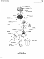
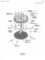
Cutter-Water Tank Parts, FIGURE 7-8 ....................................................................................................... 7-9
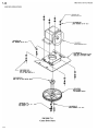
Cutter Drive Parts, FIGURE 7-9 ................................................................................................................. 7-10
Cutter Parts, FIGURE 7-10 ......................................................................................................................... 7-11
Thermal Expansion Valve, FIGURE 7-11................................................................................................... 7-12
TXV Part #'s, TABLE 7-3........................................................................................................................... 7-12
Checking Superheat..................................................................................................................................... 7-12
Recommended Superheat Setting, TABLE 7-4 ........................................................................................... 7-13
Expansion Valve Adjustment Procedure & Installation .............................................................................. 7-13
Solenoid Valves, FIGURE 7-12 .................................................................................................................. 7-14
Solenoid Valves Parts, TABLE 7-5............................................................................................................. 7-14
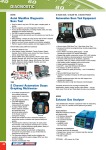
Freezer Pressure Switches ........................................................................................................................... 7-15
Freezer Pressure Switch (Allen-Bradley), FIGURE 7-13............................................................................ 7-15
High/Low Pressure Switch, FIGURE 7-14.................................................................................................. 7-16
Head Pressure.............................................................................................................................................. 7-17
Air-Cooled Units ......................................................................................................................................... 7-17
Condenser Fan Switch, FIGURE 7-15 ........................................................................................................ 7-17
Air Cooled Condenser Cleaning.................................................................................................................. 7-17
Cold Weather Kit Replacement Parts, TABLE 7-6 ..................................................................................... 7-17
Air Cooled Condenser Data, TABLE 7-7.................................................................................................... 7-18
Condenser Dimensions, FIGURE 7-16 ....................................................................................................... 7-18
Condenser Wiring, FIGURE 7-17 ............................................................................................................... 7-19
Water Cooled Units ..................................................................................................................................... 7-19
Water Regulating Valve, FIGURE 7-18...................................................................................................... 7-19
5/26/11
HES Series Service Manual
v
TABLE OF CONTENTS
Page No.
7. SERVICE OPERATIONS (Cont.)
Water Regulating Valve Part #'s, TABLE 7-8............................................................................................. 7-19
Water Cooled Condenser Service................................................................................................................ 7-20
Compressor Crankcase Heater, TABLE 7-9................................................................................................ 7-20
Compressor Motor Rotation ........................................................................................................................ 7-20
Scroll Compressor, FIGURE 7-19 .............................................................................................................. 7-21
Compressor Info, TABLE 7-10 ................................................................................................................... 7-21
Compressor Suction Rota-lock Valve, FIGURE 7-20, TABLE 7-11 .......................................................... 7-22
Compressor Discharge Rota-lock Valve, FIGURE 7-21, TABLE 7-12 ...................................................... 7-23
Short Circuit Protection, FIGURE 7-22 ...................................................................................................... 7-24
Control Circuit Protection ........................................................................................................................... 7-24
Motor Short Circuit Protection.................................................................................................................... 7-25
Motor Over Current Protection ................................................................................................................... 7-25
Overload Heater Pack Settings, TABLE 7-13 ............................................................................................. 7-25
Motor Overloads, FIGURE 7-23 ................................................................................................................ 7-25
Ice Bin Control, FIGURE 7-24 ................................................................................................................... 7-26
Programming Electronic Bin Thermostat .................................................................................................... 7-26
Bin Thermostat Mounting Location, FIGURE 7-25.................................................................................... 7-27
Electronic Bin Thermostat Error Messages ................................................................................................. 7-27
Thawing Timer, FIGURE 7-26.................................................................................................................... 7-28
Thawing Timer ............................................................................................................................................ 7-28
Selector Switch, FIGURE 7-27 ................................................................................................................... 7-28
Pumping Down Freezer ............................................................................................................................... 7-29
Pumping Down Entire System..................................................................................................................... 7-29
Removal of Refrigerant From the Machine ................................................................................................. 7-29
Refrigerant Leaks ........................................................................................................................................ 7-30
Non-Condensable Gases.............................................................................................................................. 7-30
Compressor Motor Burnout......................................................................................................................... 7-30
Cylinder Ice to Crushed Ice Conversion...................................................................................................... 7-31
Cylinder to Crushed, Terminal Block jumper Locations, FIGURE 7-28 .................................................... 7-31
Recommended Freezer Pressure Setting, TABLE 7-14............................................................................... 7-31
Freezer Pressure Switch, FIGURE 7-29 ...................................................................................................... 7-31
Recommended Ice Weights/Cycle, TABLE 7-15........................................................................................ 7-31
Single to Dual Ice Conversion..................................................................................................................... 7-31
Defrost Pressure Switch (DPS), FIGURE 7-30 ........................................................................................... 7-32
Defrost Pressure Switch Wiring, FIGURE 7-31.......................................................................................... 7-32
Oil Separator, FIGURE 7-32....................................................................................................................... 7-33
5/24/11
vi
HE S Series Service Manual
TABLE OF CONTENT
Page No.
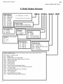
8. MODEL NUMBER STRUCTURE FOR HES MACHINES................................................................. 8-1
9. TABLES AND CHARTS
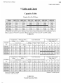
Ice Capacity TABLE 9-1............................................................................................................................. 9-1
Normal Operating Vitals, TABLE 9-2 ........................................................................................................ 9-1
Temperature-Pressure Chart, TABLE 9-3 ................................................................................................... 9-2
English-Metric Conversion, TABLE 9-4..................................................................................................... 9-3
Constants, TABLE 9-5 ................................................................................................................................ 9-3
10. TECHNICAL SERVICE BULLETINS ................................................................................................ 10-1
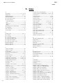
11. INDEX .................................................................................................................................................... 11-1
5/24/11
Blank page
5/24/11
Blank page
5/24/11
4-1
HES Series Service Manual
ELECTRICAL CONTROLS & THEIR FUNCTIONS
4. Electrical Controls & Their Functions
FIGURE 4-1A
Control Panel (Cover Removed)
Note: Machines manufactured after May 1999 will use Allen-Bradley controls
FIGURE 4-1B
Control Panel with Hoffman Enclosure (Door Open)
5/24/11
4-2
HES Series Service Manual
ELECTRICAL CONTROLS & THEIR FUNCTIONS
Vogt Part #
Reference
BC1
BC2
C
CB1
CB2
CB3 & CB4
CPA
CU
FPS1
FPS2
FU1-FU3
FU10 & FU20
P
PB1
PLF
PLC
R
SS
Cutler-Hammer
12A2117G09
12A2117G09
12A7516E10
12A7518E15
12A7515E18
12A7515E19
12A7515E20 (QTY 2)
N/A
12A7530E11
12A7508H2108
12A2117E04
12A2117E04
N/A
N/A
12A7530E11
12A7508H2109
12A7500E45
N/A
SAME
12A7517E18
12A7500E43
12A7500E44
TB N / A
TEST N / A
1LT 12A7500E46
*Note: AIR COOLED ONLY
Allen-Bradley
SAME
SAME
12A7516E26
12A7518E30
SAME
SAME
12A7515E21
12A7700P02
12A7516E23
12A7538E01
SAME
SAME
12A7504E13
12A7504E14
12A7516E23
12A7538E01
12A7500E56
12A7500E75
12A7537S06
12A7536M01
12A7517E27
SAME
12A7500E61
12A7500E73
N/A
N/A
12A7500E65
Description
CRUSHED ICE BIN CONTROL (DUAL ICE ONLY)
CYLINDER ICE BIN CONTROL
COMPRESSOR CONTACTOR
COMPRESSOR AUX CONTACT
PUMP / CUTTER MOTOR CIRCUIT BREAKER (10 AMP)
* CONDENSER FAN MOTOR CIRCUIT BREAKER (15 AMP)
CONTROL CIRCUIT BREAKER (3 AMP)
COPELAND PERFORMANCE ALERT
CUTTER MOTOR STARTER / CONTACTOR
CUTTER OVERLOAD HEATERS (3.38-5.54 A) / OL RELAY (2-7 A)
FREEZER PRESSURE SWITCH (DUAL ICE ONLY)
FREEZER PRESSURE SWITCH
CONDENSER FAN MOTOR FUSES, 6A, 600V (400/460V MACH)
CONTROL CIRCUIT FUSES, 7A, 600V (400/460V MACH)
PUMP MOTOR STARTER / CONTACTOR
PUMP OVERLOAD HEATERS (4.96-8.16 AMPS) / OL RELAY (2-7 A)
HARVEST / START BUTTON
CONTACT BLOCK (FOR ALLEN-BRADLEY ONLY)
POWER LINE FILTER (CE MACHINES ONLY)
PROGRAMMABLE CONTROLLER
REVERSING RELAY (DUAL ICE ONLY)
5 POSITION SELECTOR SWITCH (DUAL ICE)
3 POSITION SELECTOR (SINGLE ICE)
CONTACT BLOCK (FOR ALLEN-BRADLEY ONLY)
TERMINAL BLOCK
TEST BLOCK (ON CUTLER-HAMMER - FACTORY USE ONLY)
FAULT INDICATOR LIGHT
TABLE 4-1
Control Panel Parts List
5/24/11
HES Series Service Manual
4-3
ELECTRICAL CONTROLS & THEIR FUNCTIONS
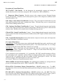
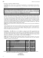
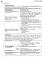
Description of Control Panel Parts.
*BC1 and BC2. Bin Controls. Ice bin thermostats for automatically stopping and starting the
machine based on the ice level in the storage bin. BC1 (Crushed Ice). BC2 (Cylinder Ice).
C. Compressor Motor Contactor. Provides power to the compressor motor. Energized during
freezing and thawing. Normally closed contact provides power to the compressor crankcase heater
when the machine is off.
CB1. Pump / Cutter Motor Circuit Breaker (10 amps). Two pole magnetic circuit breaker used for
short circuit protection in the cutter or pump motor circuit. If breaker trips, power is removed from
control circuit, shutting machine down.
CB2. Condenser Fan Motor Circuit Breaker (15 amps). Two-pole thermal magnetic circuit breaker
used for short circuit protection in the condenser motor circuit. If breaker trips, power is removed from
condenser only. Machine will eventually shut off on high discharge pressure.
CB3 and CB4. Control Circuit Breaker (3 Amps). Current limiting thermal magnetic circuit breaker
used as overload and short circuit protection for crankcase heater, PLC outputs and other control circuit
components.
CPA. Copeland PerformanceAlert. Device that monitors compressor current, phase and temperature
and shuts off machine if a problem is detected.
CU. Cutter Motor Starter.
Cutler-Hammer: A three phase motor starter with adjustable bimetallic heater packs, wired for use with
single-phase motor. Cutter Motor Overload (heater packs) – Class 10 overloads rated 3.38 - 5.54 Amps
set at cutter motors FLA rating. Pull "Reset" button to test overload.
Allen-Bradley: Motor starter made of 3-pole contactor and solid-state overload relay, wired for use
with single-phase motor. Overload - Class 10 rated 2 - 7 Amps set at cutter motors FLA rating. Press
"TEST" button to test overload.
Can be configured to reset automatically (“A”) or manually (“M”). PLC controlled machines will have
the overload reset in the “automatic” position. When an overload condition occurs, an auxiliary contact
signals the PLC of a problem and shuts the machine off (PLC input light # 5 will be “off” when
overload is tripped). Will automatically reset after an overloads cool.
See Section 7, Motor Over Current Protection for details.
*FPS1 and FPS2. Freezer Pressure Switches. For regulating the ice thickness by sensing the freezer
pressure and initiating the thaw period. FPS1 (Crushed Ice). FPS2 (Cylinder Ice).
FU10 & FU20. Transformer Primary Protection Fuses - 400/460V machines only. (7A, 600V,
time delay fuses). Fuses used for transformer primary protection along with control circuit upstream of
CB3/CB4.
FU1, FU2 & FU3. Condenser Fan motor Fuses - 400/460V machines only. (6A, 600V, Time delay
fuses). Fused used for short circuit protection in the condenser motor circuit. If fuse(s) blows, power is
removed from condenser only. Machine will eventually shut off on high discharge pressure.
5/24/11
4-4
HES Series Service Manual
ELECTRICAL CONTROLS & THEIR FUNCTIONS
P. Pump Motor Starter.
Cutler-Hammer: A three phase motor starter with adjustable bimetallic heater packs, wired for use on
single phase. Pump Motor Overload (heater packs) – Class 10 overloads rated 4.96 – 8.16 Amps set at
pump motors FLA rating. Pull "Reset" button to test overload.
Allen-Bradley: Motor starter made of 3-pole contactor and solid-state overload relay, wired for use
with single-phase motor. Overload - Class 10 rated 2 - 7 Amps set at pump motors FLA rating. Press
"TEST" button to test overload.
Can be configured to reset automatically (“A”) or manually (“M”). PLC controlled machines will have
the overload reset in the “automatic” position. When an overload condition occurs, an auxiliary contact
signals the PLC of a problem and shuts the machine off (PLC input light # 5 will be “off” when
overload is tripped). Will automatically reset after an overloads cool.
See Section 7, Motor Over Current Protection for details.
PB1. Start/ Harvest button. For starting the machine in the ice-making mode. Momentary contact or
initiating a harvest cycle if the machine is in the freeze mode. Can be used to bypass the built in 120
minute start-up mode delays as well as terminate a harvest cycle.
PLC. Programmable Logic Controller. For monitoring, sequencing, and controlling various
functions of the Tube-Ice® operation. Also has a built in thaw timer for controlling the time of the
thawing period. Thawing time is adjustable from 1 1/2 to 5 minutes.
PLF. Power Line Filter. Used on “CE” approved machines only. Used to reduce amount of noise on
incoming power lines.
*R. Reversing Relay. Switches machine to crush ice by making or breaking various circuits
concerning crushed ice production. Energized during crushed ice production only.
SS. Selector Switch.
Dual Ice machines – Five positions switch for the purpose of selecting form five different machine
modes. Clean / crushed / cylinder / Both (cyl & crushed) / off.
Single Ice machines – Three position switch for the purpose of selecting from three different machine
modes, clean / Ice / off.
1LT. Fault indicator light (24VDC light) flashes a designated number of times. A non-auto restart fault
occurs or a auto-restart fault occurs three consecutive times.
*Note: Components used in dual ice type machines only.
5/24/11
4-5
HES Series Service Manual
ELECTRICAL CONTROLS & THEIR FUNCTIONS
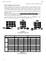
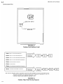
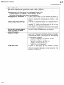
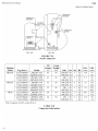
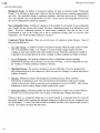
Wiring And Electrical Connection.
Refer to TABLE 4-1 below to properly size wiring connections. A fused disconnect must be
provided near the Tube-Ice® machine. Connect 3-phase power to terminals L1, L2, L3 for operation
of the Tube-Ice® machine and its controls. If one leg of the 3 phase power is higher or lower
(“Wild”), then it should be connected to terminal #L2. Connect the “Ground” wire to the “Ground”
terminal provided. On dual voltage, 50 Hz machines, the 220V single phase should be connected to
terminals L4 and L5.
Note: When initially starting the machine, the scroll compressor must be phased properly. If the
compressor is run backwards for an extended period of time, the compressor may be damaged. See
Section 7, Compressor Motor Rotation for details.
Air-cooled condenser should be wired to terminals 20,21,22 and 23 (see FIGURES 4-9, 4-10).
460V air cooled condensers should be wired to terminals B1, B2, B3, 22 & 23.
FIGURE 4-2
Terminal Block Connections
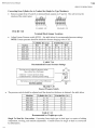
Standard Voltages:
Model
Voltage
HES20 208/230, 3p, 60 hz
460, 3p, 60 hz
220, 3p, 50 hz
400, 3p, 50 hz
F.L.A.
18.0
9.0
19
9.5
Water Cooled
Min. Ampacity Max. Fuse F.L.A.
20.9
30
21.4
10.4
15
10.3
21.0
35
22.4
10.9
15
10.8
Max. Fuse
35
20
35
15
HES30
208/230, 3p, 60 hz
460, 3p, 60 hz
220, 3p, 50 hz
400, 3p, 50 hz
21.6
10.7
22.6
11.2
25.4
12.6
26.4
13.1
40
15
40
20
25.5
12.0
26.5
12.5
29.3
13.9
30.3
14.4
40
20
45
20
HES40
208/230, 3p, 60 hz
460, 3p, 60 hz
220, 3p, 50 hz
400, 3p, 50 hz
27.3
13.3
28.3
15.3
32.5
15.8
33.5
18.2
50
30
50
25
35.1
17.3
36.1
17.9
40.3
19.8
41.3
20.8
60
30
60
30
TABLE 4-2
Electrical Specifications
5/24/11
Air Cooled
Min. Ampacity
24.3
11.7
25.3
12.2
4-6
HES Series Service Manual
ELECTRICAL CONTROLS & THEIR FUNCTIONS
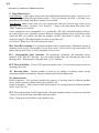
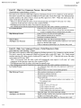
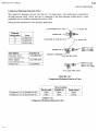
Electrical Specifications “PLC” (Programmable Logic Controller)
Sequence Of Controller & Machine Operation
NOTE: Part #12A7536M01. PLC must be pre-programmed for specific model.
FIGURE 4-3
PLC Display (Fxo shown above)
PLC Inputs
#
0
1
2
3
4
5
6
7
PLC Outputs
Description
Cylinder Ice Indicator
Crushed Ice Indicator
Freezer Pressure Switch
Start / Manual Harvest
Clean Switch
Pump / Cutter Overload (“off” when tripped)
High / Low Pressure safety (“off” when tripped)
N/A
#
0
1
2
3
4
5
Description
Machine Fault Indicator Light
"A" valve
Compressor
Reversing Relay (Dual Ice only)
Water Pump
Cutter / "D" valve / Suction Stop
TABLE 4-3
PLC Inputs & Outputs
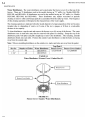
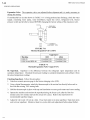
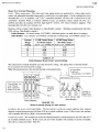
Explanation. The HES-Series Tube-Ice® machine is controlled by a PLC (Programmable Logic
Controller). The PLC controls the sequence of events and monitors the ice machine functions. The
operational sequences of the HES-Series Tube-Ice® machine can be described best as a series of eight
different modes. Each mode identifies and defines a sequence of events that occur while in that mode
and thereby cause it to move to the next mode. Only one mode is active at a time.
Start-Up Mode. The start-up mode is a function, which prevents the premature automatic starting of
the machine at the time of installation, after a power interruption, or after a safety trip. Its normal time
period is two hours. The start-up mode may be bypassed at any time by pressing the “Harvest/Start”
button to immediately advance to the standby mode.
! CAUTION !
If the power has been turned off to the machine, make sure the compressor crankcase is warm
And there is no liquid refrigerant in with the oil before restarting the unit.
! CAUTION !
5/24/11
4-7
HES Series Service Manual
ELECTRICAL CONTROLS & THEIR FUNCTIONS
Standby Mode. The standby mode is a decision-making mode. It monitors the position of all the
various switches in the control circuit and at the proper time decides which mode to advance to next.
Freeze Mode (Freeze Cycle). The freeze mode is active during the normal ice making cycle. During
this time, the circulating water pump and compressor are running and the “A” (liquid feed) solenoid
valve and “X” solenoid valve compressor discharge (AC units only) is open.
Harvest Mode (Thaw Cycle). The harvest mode is normally initiated at the termination of the freeze
mode. At this time, the circulating water pump stops and the “A” (liquid feed) solenoid valve closes.
After seven seconds, the “D” (thaw gas) solenoid valve opens, the “SS” (suction stop) solenoid valve
closes, the cutter motor starts and the thaw timer is activated.
The harvest mode is terminated by the thaw (harvest) timer at which time the machine will begin
another freeze cycle. The harvest mode can also be terminated manually by pushing in the
“Harvest/Start” button.
NOTE: If the “Selector Switch” switch is in the “Off” position or the bin control is satisfied the
machine will advance to the partial pumpdown mode before shutting off (standby mode).
Partial Pumpdown Mode. The partial pumpdown mode precedes the normal off or standby mode. Its
purpose is to transfer a portion of the liquid from the suction accumulator and freezer into the receiver
prior to shutdown of the machine (standby mode). This will discourage any migration of liquid
refrigerant to the compressor during the off or standby mode. It is also intended to prevent any liquid
refrigerant slugging to the compressor when the machine restarts in a freeze mode.
When partial pumpdown is initiated, the “A” (liquid feed) solenoid valve is closed and the water pump
and compressor run for a set time. After this set time the compressor stops and the machine is in the
standby mode.
Model
Time
HES-20
7 minutes
HES-30
5 minutes
HES-40
3 minutes
TABLE 4-4
Partial Pumpdown Time
NOTE: The PLC uses the cylinder ice pressure switch (FPS2) as a partial pumpdown safety. Do not
remove this pressure switch from the machine.
Total Pumpdown Mode. The function of the total pumpdown mode is to transfer all of the liquid
refrigerant from the freezer (evaporator) into the receiver. Total pumpdown is initiated as the first
phase of and prior to entering the “Clean” mode.
Its main purpose is to clear the freezer of liquid refrigerant and prevent possible refrigerant migration to
the compressor while running the “Clean” cycle. It can also be used to check the units total refrigerant
charge, isolate the refrigerant in the receiver while making repairs, or prepare the machine for
disconnecting and moving.
To restart the machine after a total pumpdown, put the “Selector Switch” switch in the “Ice” position
and press the “Harvest/Start” button. At this time the “A” (liquid feed) solenoid valve will open for
two minutes, allowing refrigerant to feed into the freezer before the machine starts into a freeze cycle.
5/24/11
4-8
HES Series Service Manual
ELECTRICAL CONTROLS & THEIR FUNCTIONS
Clean Mode. The “Clean” mode is considered to be maintenance or servicing function of the machine.
During this mode only the water pump will run. The first phase of the “Clean” mode is a total
pumpdown.
! CAUTION !
Do not attempt to bypass the total pumpdown phase of the “Clean” mode. If a clean cycle is
performed without first completing a total pumpdown, the warm water being circulated through
the freezer tubes can force refrigerant to migrate to the suction accumulator and compressor
which can cause compressor damage when returning to the freeze mode.
! CAUTION !
After the total pumpdown, the water pump can be stopped by simply moving the “Selector Switch”
from the “Clean” to the “Off” position. To restart the water pump, move the “Selector Switch” back to
the “Clean” position and press the “Harvest/Start” button. (Note: If the freezer and compressor suction
pressure have come up enough to open the freezer pressure switch FPS2 and close low pressure safety
switch 4PS, the compressor will come on and pump down the freezer again.) Ice machine cleaning
solution can be circulated though the tubes to accomplish the cleaning procedure. If the water pump is
left to run in the clean mode for more than two hours, the PLC will shut the machine off. The clean
mode can be resumed by pushing the “Harvest/Start” button.
NOTE: Running in Clean mode for extended period of time can cause excessive pressure to build up in
the freezer.
At the termination of the clean mode, the machine can be returned to ice making mode by putting the
“Selector Switch” in the “Ice” position and pressing the “Harvest/Start” button. . At this time the “A”
(liquid feed) solenoid valve will open for two minutes, allowing refrigerant to feed into the freezer
before the machine starts into a freeze cycle.
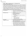
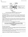
Fault Mode.
The HES Series (“S” for Smart) is equipped with a PLC (programmable logic
controller) that controls all aspects of the operation. One of the functions of the PLC is to shut down
the machine when a problem arises and send a signal to the fault indicator light located on the far-left
side of the electrical panel. The red light is visible through the opening in the front casing and will
blink when a problem has caused the machine to shut down (See FIGURE 4-2).
NOTE: The Fault Light will flash the designated number of times ONLY if the fault is a not a autorestart fault or a auto-restart fault that has occurred three consecutive times. For your reference,
TABLE-4-3 contains a list of fault codes.
#
Description
Restart
Off Delay
1
High / Low Press - Freeze
No
N/A
2
High / Low Press - Harvest
No
N/A
3
High / Low Press - Partial Pumpdown
No
N/A
4
High / Low Press - Total Pumpdown
No
N/A
5
Short Cycle
Yes
2 hrs
6
Long Cycle
No
N/A
7
Pump Motor Overload
Yes
30 min
8
Cutter Motor Overload
Yes
30 min
N/A
Power Failure
Yes
2 hrs
NOTE: The machine may be off on a fault and not flashing an error code if the fault is an auto-restart
fault and it is not the third consecutive occurrence of this fault.
TABLE 4-5
PLC Fault Codes
5/24/11
4-9
HES Series Service Manual
ELECTRICAL CONTROLS & THEIR FUNCTIONS
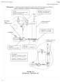
Copeland Performance Alert (CPA). This device is used to monitor the compressor discharge
temperature, compressor current and phase, as well as control voltage to the compressor contactor. If
a problem is detected, the compressor will shut off. The fault light on the CPA will flash a certain
number of times to indicate the fault that occurred. See table below.
NOTE: When this occurs, the ice machine will continue to run but the compressor will not be on.
The ice machine will eventually shut off on a “Long Cycle Fault”.
Some faults, referred to as “lockout” faults, will require cycling power to the Performance Alert to
reset. This can be done by switching CB1 to the “off” position for 5 seconds, then back “on”.
NOTE: If ice machine has a High/Low pressure fault, the Performance Alert can detect low control
voltage at the compressor contactor and flash 9 times. This will clear when the machine is re-start.
FIGURE 4-4
Copeland Performance Alert Wiring
Alert Codes System Conditions
Description
1
High Discharge Temperature
4
Lock Rotor
6
Missing Phase
7
Reverse Phase (Scroll only)
8
Welded Contactor
9
Low Voltage
11
DLT Sensor Failure
Discharge Temperature above set point
(default 230 Deg F) adjustable 170 to 281
4 Consecutive Compressor trips after run time of 1 to
15 seconds indicating compressor won't start
Demand signal is present but current is missing in
one phase
Demand signal is present but current is not detected in
the correct sequence
No demand signal but current has been detected in one
or both phases
Control voltage dips below 85V for 110V or 170V for
220V
Discharge Temperature Sensor short or open circuit
Note:
Faults 1, 4, 6, 7, 9 will shut off compressor with a off time of 20 minutes (adjustable from 10 to 40 minutes).
If fault 1, 4, 6 or 7 occurs ("LOCKOUT"), fault must be manually reset by cycling power to the Performance Alert.
Lockout Configuration
Code
1
4
6
7
High Discharge Temp
Locked Rotor
Missing Phase
Reverse Phase
Minimum
Maximum
Default
2
2
1
1
6
10
10
1
4
4
10
1
TABLE 4-6
Copeland Performance Alert Codes
5/24/11
4-10
HES Series Service Manual
ELECTRICAL CONTROLS & THEIR FUNCTIONS
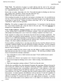
1 Flash - High / Low Pressure Fault during Freeze
2 Flashes - High / Low Pressure Fault during Harvest
Press Harvest / Start
Button twice to
restart machine
2 Minute
Freeze
Press Harvest / Start
Button twice to
restart machine
Run water
pump for
30 Minutes
Harvest
Mode
Freeze
Mode
3 Flashes - High / Low Pressure Fault during Partial Pumpdown
4 Flashes - High / Low Pressure Fault during Total Pumpdown
5 Flashes - Short Cycle Faults (3 Consecutive)
6 Flashes - Long Cycle Fault
7 Flashes - Water Pump Motor Overload Fault (3 Consecutive)
8 Flashes - Cutter Motor Overload Fault (3 Consecutive)
2 Minute
Freeze
Note: While in the Fault Mode, if Harvest / Start Button is pressed twice and the machine does not start, one of the following is true:
* Bin control is not calling for ice or Selector switch is in the “off” position (PLC input lights 0 & 1 are “off”)
* The high / low pressure switch is tripped (PLC input light 6 is “off”)
* The Cutter or Pump overload is tripped (PLC input light 5 is “off”)
FIGURE 4-5
Machine Fault Startup Sequence
FIGURE 4-6
Fault Indicator / Selector Switch Location
5/24/11
Harvest
Mode
Freeze
Mode
4-11
HES Series Service Manual
ELECTRICAL CONTROLS & THEIR FUNCTIONS
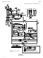
NOTE:
USE COPPER CONDUCTORS RATED 60 °C
OR HIGHER
FIGURE 4-7
Dual Ice Type
5/24/11
Machines w/Copeland Performance Alert
* Standard on machines manufactured after January 2010
4-12
HES Series Service Manual
ELECTRICAL CONTROLS & THEIR FUNCTIONS
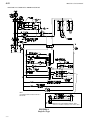
NOTE:
USE COPPER CONDUCTORS RATED 60 °C
OR HIGHER
Machines w/Copeland Performance Alert
* Standard on machines manufactured after January 2010
FIGURE 4-8
Single Ice Type
5/24/11
4-13
HES Series Service Manual
ELECTRICAL CONTROLS & THEIR FUNCTIONS
NOTE:
USE COPPER CONDUCTORS RATED 60 °C
OR HIGHER
Machines w/Copeland Performance Alert
* Standard on machines manufactured after January 2010
FIGURE 4-9
Single Ice (Dual Voltage)
50 HZ, 400V compressor, 200V controls
5/24/11
4-14
HES Series Service Manual
ELECTRICAL CONTROLS & THEIR FUNCTIONS
NOTE:
USE COPPER CONDUCTORS RATED 60 °C
OR HIGHER
Machines w/Copeland Performance Alert
* Standard on machines manufactured after January 2010
FIGURE 4-10
Single Ice (400V / 460V)
5/24/11
4-15
HES Series Service Manual
ELECTRICAL CONTROLS & THEIR FUNCTIONS
Wiring Connections to Air-Cooled Condenser.
FIGURE 4-11
Wiring For BOHN DVT005 with Cold Weather Valve and Single Fan,
50/50 Condenser Split
5/24/11
4-16
HES Series Service Manual
ELECTRICAL CONTROLS & THEIR FUNCTIONS
FIGURE 4-12
Wiring For BOHN DVT008 with Cold Weather Valve and Single Fan,
50/25/25 Condenser Split
5/24/11
4-17
HES Series Service Manual
ELECTRICAL CONTROLS & THEIR FUNCTIONS
FIGURE 4-13
Wiring For BOHN DVT012 /DVT016 with Cold Weather Valve and Two Fan,
50/50 Condenser Split
5/24/11
Blank page
5/24/11
HES Series Service Manual
7-16
SERVICE OPERATIONS
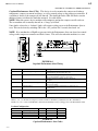
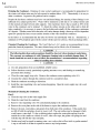
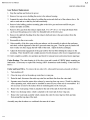
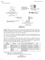
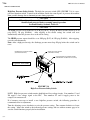
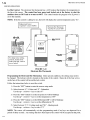
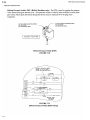
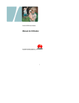
High/Low Pressure Safety Switch. The high-low pressure switch (4PS) (FIGURE 7-14) is a twopole dual function switch. Located in the machine outside the control panel, it protects the machine
from possible damage due to abnormal pressure during operation.
! CAUTION !
When this switch causes the machine to stop, the cause should be
identified and corrected before resuming normal operation.
See Fault Identity, Section 6, Table 6-2.
! CAUTION !
The LOW pressure cut-in should be set at 40 psig (R-22), 50 psig (R-404A) and the cutout set at 20
psig (R-22), 30 psig (R-404A). After tripping at the cutout setting, the switch will reset
automatically when the pressure rises to the cut-in setting.
The HIGH-pressure cutout should be set at 300 psig (R-22) & 350 psig (R-404A). After tripping,
reset the switch manually.
Note: After a high-pressure trip, the discharge pressure must drop 50 psig before the switch can be
reset.
DIFFERENTIAL ADJUSTING SCREW
(CCW RAISES SETTING)
RANGE ADJUSTING SCREW
(CW RAISES SETTING)
HIGH PRESSURE ADJUSTMENT SCREW
(DIFFERENTIAL FACTORY SET AT 55 PSIG)
Vogt Part #: 12A2117D02
FIGURE 7-14
High /Low Pressure Safety Switch
NOTE: High-low pressure switch contains both high and low voltage circuits. Line numbers 12 and
X6 supply a low voltage signal to the PLC. Line numbers Y2 and 18-supply power to the
compressor contactor coil.
If it becomes necessary to install a new high/low pressure switch, the following procedure is
recommended for its adjustment:
Turn the adjusting screws clockwise to raise the pressure setting. Turn counter-clockwise to lower
the setting. Adjust the switch to the indicated pressure settings and test with an accurate gage to be
sure the switch functions properly before installation.
5/26/11
HES Series Service Manual
7-17
SERVICE OPERATIONS
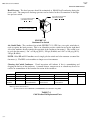
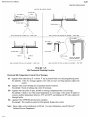
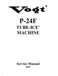
Head Pressure. The head pressure should be maintained at 100-105 degF condensing during the
freeze cycle. The compressor discharge pressure can be checked at the test connection on the highlow pressure switch.
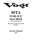
CUT IN ADJUSTING SCREW
(CW LOWERS SETTING)
CUT IN ADJUSTING SCREW
(CW RAISES SETTING)
Vogt Part #: 12A2117F08
FIGURE 7-15
Condenser Fan Switch
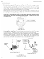
Air-Cooled Units. The condenser fan switch (FIGURE 7-15) (CPS) has a two-pole switch that is
used to regulate the head pressure. This is an adjustable pressure switch located on the right-hand
side of the machine directly controls the operation of the condenser fan motor(s). The switch is set
to cycle the fan motor(s) “On” at 210 psig (R-22), 250 psi (R-404A) and “Off” at 190 psig (R-22),
230 psi (R-404A).
NOTE: Older HE and R12 machines used a single pole fan switch and a fan contactor to control the
fan motor (s). The HE S-series machine no longer uses a fan contactor.
Cleaning Air-Cooled Condenser. Visual inspection will indicate if dirt is accumulating and
clogging the fin face of the condenser. A vacuum cleaner, compressor air or a brush may be used to
remove an accumulation of dirt from the fin section of the condenser.
Condenser
DVT005
DVT008
DVT012
DVT016
Description
5/8” N.O.
7/8” N.O.
1 1/8” N.O.
Solenoid Valve
Valve
Valve Rebuild Kit
12A4200A0503
12A4199V42
12A4200A0704
12A4199V44
12A4200A0902
12A4199V45
12A4200A09021
12A4199V55
Replacement Coil
12A2105C04
12A2105C04
12A2105C04
12A2105C25
Note: Sporlan Solenoid Valves
Sporlan Solenoid valve OE34S290 (12A4200A0902) discontinued in Aug 2006
TABLE 7-6
Cold Weather Kit Replacement Parts
5/26/11
Thermostats
Fan
Solenoid
Penn A19
Penn A319
HES Series Service Manual
7-18
SERVICE OPERATIONS
Ice Machine Model
Recommended Condenser
HE20
HE30
HE40
DVT005
(DVT008)
DVT008
(DVT012)
DVT012
(DVT016)
Note: For continuous operation at ambient above 90 °F, use larger condenser shown in parenthesis
Total Heat Rejection:
(15°F TD)
Fans:
Full Load Amps:
Weight, lbs.:
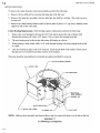
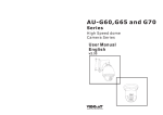
Condenser dimensions, inches:
Recommended Line Sizes,
OD:
Connections at Condenser:
Connections at Machine:
BTU/hr at 60 Hz.
BTU/hr at 50 Hz.
Number
HP, Each
Total, CFM
1 ph., 208/230V, 60 Hz
3 ph., 208/230V, 60 Hz
3 ph., 460V, 60 Hz
1 ph., 200/220V, 50 Hz
3 ph., 200/220V, 50 Hz
3 ph., 400V, 50 Hz
Net
Shipping
Operating (maximum flooded)
A (Width)
B (Length)
C (Height)
D (Leg centerline)
E (Leg centerline)
F (Clearance below)
Liquid (All lengths and orientations)
Discharge Gas Vertical Up, All lengths
Horizontal Or Down, < 75 ft.
Horizontal Or Down, > 75 ft.
Liquid (ODC)
Discharge Gas (ODC)
Liquid & Discharge Gas (ODC)
35,700
32,800
1
1/3 (1/2)
5,050 (6,450)
3.4 (3.9)
N/A
1.3 (1.3)
3.4 (3.9)
N/A
1.3 (1.3)
180 (260)
320 (390)
195 (285)
43”
39.75” (49.75”)
30” (40”)
17”-3
30” (40”)
24.5”
1/2”
5/8”
5/8”
7/8”
5/8”(7/8”)
7/8” (1 1/8”)
1-1/8”
TABLE 7-7
Air-Cooled Condenser Data
FIGURE 7-16
Condenser Dimensions
5/26/11
58,800
54,100
1 (2)
1/2
6,450 (12,400)
3.9 (7.8)
N/A
1.3 (2.6)
3.9 (7.8)
N/A
1.3 (2.6)
260 (470)
390 (520)
285 (500)
43”
49.75” (69.75”)
40” (60”)
17” - 3
40” (60”)
24.5”
5/8”
7/8”
7/8”
1-1/8”
7/8”
1 1/8”
1-1/8”
117,500
108,100
2
1/2
12,400 (12,900)
7.8 (7.8)
N/A
2.6 (2.6)
7.8 (7.8)
N/A
2.6 (2.6)
470 (530)
520 (680)
500 (560)
43”
69.75”
60”
17” - 3
60”
24.5”
7/8”
1-1/8”
1-1/8”
1-3/8”
7/8”
1-1/8” (1-3/8”)
1-1/8”
HES Series Service Manual
7-19
SERVICE OPERATIONS
FIGURE 7-17
Wiring For BOHN DVT012 /DVT016 with Cold Weather Valve and Two Fan,
50/50 Condenser Split
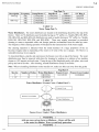
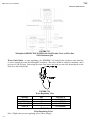
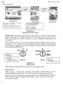
Water-Cooled Units. A water-regulating valve (FIGURE 7-18) located in the condenser water inlet line
is used to control the water flow through the condenser. This valve should be adjusted to maintain a head
pressure of 190-210 psig. Increasing the water flow lowers the head pressure and decreasing the water
flow raises the head pressure.
FIGURE 7-18
Water Regulating Valve
Machine
HES-20 & HES-30
HES-40
* HES-20 & HES30
* HES-40
Size
3/4”
1”
1/2”
1”
TABLE 7-8
Water Regulating Valves
Note: * High water pressure regulating valves (above 90 psig)
5/26/11
Vogt Part #
12A4200E0605
12A4200E0802
12A4200E0402
12A4200E0801
HES Series Service Manual
7-20
SERVICE OPERATIONS
Water Cooled Condenser Service. High head pressure due to fouled condenser.
Eliminate other possible causes:
• Non-condensables
• Faulty gauge
• Refrigerant restriction
• Water regulating valve
• High inlet water temperature
• Insufficient water supply
Example
Liquid return (RCVR) Psig = 200 = 102°F (SAT)
Water outlet temperature
= 95°F
Difference
= 7°F
If difference is more than 10°F, cleaning is indicated. For cleaning procedure see, “Water Cooled
Condenser Cleaning”, Section 5.
Compressor Crankcase Heater. When electrical power is supplied to terminals L1, L2 & L3 of the
control panel, the crankcase heater is energized when the compressor is not operating. The purpose
of the crankcase heater is to keep the compressor warm to prevent the migration of refrigerant to the
compressor while the compressor is not running.
Machine
HES-20/HES-30/HES-40
Size
70 watts (at 230V)
Vogt Part #
12A 7509E13
TABLE 7-9
Compressor Crankcase Heaters
! CAUTION !
In case of a power interruption, or crankcase heater failure, be sure the compressor crankcase
is warm prior to restarting the machine manually
! CAUTION !
Compressor Motor Rotation. Scroll compressors must be phased properly at startup. Connect
pressure gages to the high and low side of the compressor at the High / Low Pressure safety switch.
Start machine by putting "Selector Switch" in the "Ice" position and pressing "Start / Harvest"
button. The compressor discharge pressure should start to rise as the suction pressure drops. Within
30 seconds, the discharge pressure should be approximately 180 - 200 psig. If the discharge pressure
does not rise, and the suction pressure does not drop, the compressor is running backwards. Shut
machine off power to the machine at the main disconnect and reverse wires labeled L1 and L3 in the
compressor's electrical junction box.
5/26/11
Blank page
5/24/11
Blank page
5/24/11
HES Series Service Manual
9-2
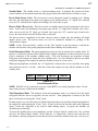
TABLES & CHARTS
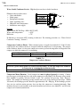
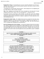
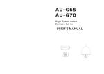
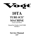
TEMPERATURE - PRESSURE CHART
FOR COMMON REFRIGERANTS
DegF
-50
-48
-46
-44
-42
-40
-38
-36
-34
-32
-30
-28
-26
-24
-22
-20
-18
-16
-14
-12
-10
-8
-6
-4
-2
0
2
4
6
8
10
12
14
16
18
20
22
24
26
28
30
32
34
36
38
40
42
44
46
48
50
R-12
-7.6
-7.2
-6.8
-6.3
-5.8
-5.4
-4.9
-4.4
-3.8
-3.3
-2.7
-2.1
-1.5
-0.8
-0.1
0.6
1.3
2.1
2.8
3.7
4.5
5.4
6.3
7.2
8.2
9.2
10.2
11.2
12.3
13.5
14.6
15.8
17.1
18.4
19.7
21.0
22.4
23.9
25.4
26.9
28.5
30.1
31.7
33.4
35.2
36.9
38.8
40.7
42.7
44.7
46.7
R-22
-3.0
-2.4
-1.7
-1.0
-0.2
0.5
1.3
2.2
3.0
4.0
4.9
5.9
6.9
7.9
9.0
10.1
11.3
12.5
13.8
15.1
16.5
17.9
19.3
20.8
22.4
24.0
25.6
27.3
29.1
30.9
32.8
34.7
36.7
38.7
40.9
43.0
45.3
47.6
49.9
52.4
54.9
57.5
60.1
62.8
65.6
68.5
71.5
74.5
77.6
80.7
84.0
R-502 R-134a MP-39 R-404a R-402a
0.2
-9.0
-9.1
0.0
1.2
0.7
-8.7
-8.7
0.8
2.1
1.5
-8.3
-8.3
1.6
2.9
2.3
-8.0
-7.9
2.5
3.9
3.2
-7.6
-7.4
3.4
4.9
4.1
-7.1
-7.1
5.5
5.9
5.0
-6.7
-6.6
6.5
6.9
6.0
-6.3
-6.1
7.5
8.0
7.0
-5.8
-5.6
8.6
9.2
8.1
-5.3
-5.2
9.7
10.3
9.2
-4.8
-4.4
10.8
11.6
10.3
-4.2
-4.1
12.0
12.8
11.5
-3.8
-3.4
13.2
14.1
12.7
-3.0
-2.9
14.5
15.5
14.0
-2.4
-2.2
15.8
16.9
15.3
-1.8
-1.7
17.1
18.4
16.7
-1.1
-1.0
18.5
19.9
18.1
-0.4
-0.2
20.0
21.5
19.5
0.3
0.4
21.5
23.1
21.0
1.1
1.4
23.0
24.8
22.6
1.9
2.2
24.6
26.5
24.2
2.8
3.1
26.3
28.3
25.8
3.6
3.9
28.0
30.2
27.5
4.5
4.8
29.8
32.1
29.3
5.5
5.7
31.6
34.1
31.1
6.5
6.7
33.5
36.1
32.9
7.5
7.7
35.6
38.1
34.9
8.5
8.8
37.4
40.4
36.9
9.6
9.9
39.4
42.6
38.9
10.8
11.0
41.6
44.9
41.0
12.0
12.2
43.9
47.3
43.2
13.1
13.4
46.0
49.7
45.4
14.4
14.6
48.3
52.2
47.7
15.7
15.9
50.7
54.8
50.0
17.0
17.2
53.1
57.5
52.5
18.4
18.6
55.6
60.2
54.9
19.9
20.0
58.2
63.0
57.5
21.4
21.5
59.9
65.9
60.1
22.9
23.0
63.6
68.9
62.8
24.5
24.6
66.5
72.0
65.6
26.1
26.2
69.4
75.1
68.4
27.8
27.9
72.3
78.3
71.3
29.5
29.6
75.4
81.6
74.3
31.3
31.3
78.5
85.0
77.4
33.2
33.2
81.8
88.5
80.5
35.1
35.0
85.1
92.1
83.8
37.0
37.0
88.5
95.7
87.0
39.1
39.0
91.9
99.5
90.4
42.0
41.0
95.5
103.4
93.9
43.3
43.1
99.2
107.3
97.4
45.5
45.3
102.9 111.4
DegF
50
52
54
56
58
60
62
64
66
68
70
72
74
76
78
80
82
84
86
88
90
92
94
96
98
100
102
104
106
108
110
112
114
116
118
120
122
124
126
128
130
132
134
136
138
140
142
144
146
148
150
R-12
46.7
48.8
51.0
53.2
55.4
57.7
60.1
62.5
65.0
67.6
70.2
72.9
75.6
78.4
81.3
84.2
87.2
90.2
93.3
96.5
99.8
103.1
106.5
110.0
113.5
117.2
120.9
124.7
128.5
132.4
136.4
140.5
144.7
148.9
153.2
157.7
162.2
166.7
171.4
176.2
181.0
185.9
191.0
196.2
201.3
206.6
212.0
217.5
223.1
228.8
234.6
R-22
84.0
87.3
90.8
94.3
97.9
101.6
105.4
109.3
113.2
117.3
121.4
125.7
130.0
134.5
139.0
143.6
148.4
153.2
158.2
163.2
168.4
173.7
179.1
184.6
190.2
195.9
201.8
207.7
213.8
220.0
226.4
232.8
239.4
246.1
252.9
259.9
267.0
274.3
281.6
289.1
296.8
304.6
312.5
320.6
328.9
337.3
345.8
354.5
363.4
372.3
381.5
TABLE 9-3
All pressures are in lbs/in2 gage (psig).
5/25/11
R-502 R-134a MP-39 R-404a R-402a
97.4
45.5
45.3
102.9 111.4
101.0
47.7
60.0
109.0 120.0
104.8
50.1
62.0
113.0 124.0
108.6
52.3
65.0
117.0 129.0
112.4
55.0
68.0
121.0 133.0
116.4
57.5
70.0
125.0 138.0
120.4
60.1
73.0
130.0 142.0
124.6
62.7
76.0
134.0 147.0
128.8
65.5
79.0
139.0 152.0
133.2
68.3
82.0
144.0 157.0
137.6
71.2
85.0
148.0 162.0
142.2
74.2
89.0
153.0 168.0
146.8
77.2
92.0
158.0 173.0
151.5
80.3
95.0
164.0 179.0
156.3
83.5
99.0
169.0 184.0
161.2
86.8
102.0 174.0 190.0
166.2
90.2
106.0 180.0 196.0
171.4
93.6
109.0 185.0 202.0
176.6
97.1
113.0 191.0 208.0
181.9 100.7 117.0 197.0 214.0
187.4 104.4 121.0 203.0 220.0
192.9 108.2 125.0 209.9 227.0
198.6 112.1 129.0 215.0 234.0
204.3 116.1 133.0 222.0 240.0
210.2 120.1 138.0 229.0 247.0
216.2 124.3 142.0 235.0 254.0
222.3 128.5 146.0 242.0 261.0
228.5 132.9 151.0 249.0 269.0
234.9 137.3 156.0 256.0 276.0
241.3 142.8 160.0 264.0 284.0
247.9 146.5 165.0 271.0 292.0
254.6 151.3 170.0 279.0 299.0
261.5 156.1 175.0 286.0 307.0
268.4 161.1 180.0 294.0 316.0
275.5 166.1 185.0 302.0 324.0
282.7 171.3 191.0 311.0 332.0
290.1 176.6 196.0 319.0 341.0
297.6 182.0 202.0 328.0 350.0
305.2 187.5 207.0 336.0 359.0
312.9 193.1 213.0 345.0 368.0
320.8 198.9 219.0 354.0 377.0
328.9 204.7 225.0 364.0 387.0
337.1 210.7 231.0 373.0 396.0
345.4 216.8 237.0 383.0 406.0
353.9 223.0 243.0 392.0 416.0
362.6 229.4 250.0 402.0 426.0
371.4 235.8 256.0 412.0 436.0
380.4 242.4 263.0 423.0 447.0
389.5 249.2 269.0 434.0 458.0
398.9 256.0 277.0 444.0 468.0
408.4 263.0 283.0 449.0 479.0
Blank page
5/24/11
Blank page
5/24/11
HES Series Service Manual
11-1
INDEX
11. Index
A
Accumulator --------------------------------------- 3-1, 3-3, 7-2
Adapter Plate ------------------------------------------ 7-9, 7-11
Adjustable blowdown----------------------------------------- 7-3
Automatic blowdown ----------------------------------------- 7-3
Air-cooled condenser data---------------------------------- 5-8
Air-cooled condenser:
Cold weather kit parts ----------------------------------- 7-17
Data ---------------------------------------------------------- 7-18
Dimensions------------------------------------------------- 7-18
Wiring------------------------------------------------- 4-15, 7-19
Allen Bradley Pressure Switch (FPS) ----------------- 7-15
Assembly Drwgs.---------------------------------------- 7-1, 7-2
Auto-restart Fault---------------------------------------------- 6-1
"A" Valve (#20) ---------------------------- 3-2, 3-3, 7-1, 7-14
B
Bearing, Cutter----------------------------------------- 7-9, 7-11
Bill of Lading---------------------------------------------------- 2-1
Bin, Ice Storage ----------------------------------------------- 3-4
Bin, Thermostat Adjustments---------------------------- 7-26
Bin, Thermostat (Dual Ice type) --------------------------- 3-5
Bin, Thermostat Installation -------------------------------- 3-4
Bin, Thermostat (Single Ice type)------------------------- 3-5
Blowdown, Adjustable --------------------------------------- 7-3
Blowdown, Automatic ---------------------------------------- 7-3
Burnout, Compressor -------------------------------------- 7-30
C
Capacity, Calculating ---------------------------------------- 6-5
Capacity, Ice Table ------------------------------------------- 9-1
Checklist, Daily ------------------------------------------------ 5-7
Checklist, Preventive Maintenance -------------------- 5-10
Check Valve ---------------------------------------------- 3-2, 3-3
Chemical Cleaning-------------------------------------------- 5-6
Chute Assembly----------------------------------- 7-6, 7-8, 7-9
Circuit Breaker, Cutter/Pump ---------------- 4-1, 4-2, 7-24
Circuit Breaker, Control Circuit -------------- 4-1, 4-2, 7-24
Circulating Water Pump Motor ---------------------- 7-4, 7-6
Cleaning Procedure ------------------------------------------ 5-1
Clean Mode----------------------------------------------------- 4-7
Clean/Off/ Ice Selector Switch--------------------- 4-3, 7-27
Compressor -------------------------- 3-2, 3-3, 7-1, 7-2, 7-21
Compressor Burnout ---------------------------------------- 7-30
Compressor, Contactor-------------------------------- 4-1, 4-2
Compressor Crankcase Heater ------------------------- 7-20
Compressor Lubrication----------------------------- 5-8, 7-21
Compressor, Motor Burnout------------------------------ 7-30
Compressor, Motor Contactor ----------------------- 4-1, 4-2
Compressor, Motor Overload Protection ------------- 7-25
Condenser -------------------------------- 3-2, 3-3, 7-17, 7-18
Condenser, Air-cooled Cleaning -------------------------- 5-8
Condenser, Air-cooled Heat Rejection ---------------- 7-18
Condenser Fan Switch ------------------------------------ 7-17
5/24/11
Condenser, Pressure Switch (CPS) ------------------- 7-17
Condenser, Water Cooled Maintenance - 5-6, 5-7, 7-20
Control, Panel-------------------------------------------------- 4-1
Control, Panel Parts------------------------------------ 4-1, 4-2
Controller (PLC) ----------------------------------------- 4-1, 4-5
Crankcase Heater ------------------------------------------ 7-20
Crushed Ice Preferred --------------------------------------- 3-5
Cutter, Assembly------------------------ 7-6, 7-9, 7-10, 7-11
Cutter, Bearing ---------------------------- 7-7, 7-8, 7-9, 7-11
Cutter, Bearing Support ----------------------- 7-8, 7-9, 7-11
Cutter, Disc Assembly------------------------------- 7-9, 7-11
Cutter, Drive Parts ------------------------------------------ 7-10
Cutter, Gear Reducer -------------------- 7-6, 7-7, 7-9, 7-10
Cutter, Motor --------------------------------------------- 7-6, 7-9
Cutter, Over Current Protection ------------------------ 7-25
Cutter, Short Circuit Protection-------------------------- 7-24
Cutter, Parts-------------------------------------------- 7-9, 7-11
Cutter, Water Tank Parts ----------------------------------- 7-9
Cylinder to Crushed Conversion ------------------------ 7-31
D
"D" Valve (Thawing Gas #18) --------------- 3-2, 3-3, 7-14
Daily Checklist ------------------------------------------------- 5-9
Discharge, Rota-lock------------------------------- 7-12, 7-13
Divider, Bin ----------------------------------------------------- 3-4
Defrost Pressure Switch (DPS) ------------------------- 7-32
Draining Condenser ------------------------------------------ 5-6
Drip pan, maintenance -------------------------------------- 5-5
Drive gear ----------------------------------------------- 7-9, 7-10
E
Electrical Connection ---------------------------------------- 4-4
Electrical, Controls ------------------------------------------- 4-1
Electrical, Wiring Diagrams ------- 4-11, 4-12, 4-13, 4-14
Energy Saving ------------------------------------------------- 1-1
Expansion Valve ------------------------------------ 7-12, 7-13
F
Fault Identity --------------------------------------------------- 4-8
Fault Indicator Light ---------------------------------------- 4-10
Fault Mode------------------------------------------------------ 4-8
Fault Startup Sequence ----------------------------------- 4-10
FIGURE 3-1 (Air Cooled Piping Diagram) ------------- 3-2
FIGURE 3-2 (Water Cooled Piping Diagram) --------- 3-2
FIGURE 3-3 (Bin Sensor Installation) ------------------- 3-4
FIGURE 4-1A & 4-1B (Control Panel) ------------------ 4-1
FIGURE 4-2 (Wiring & Electrical Connections)------- 4-5
FIGURE 4-3 (PLC Display)--------------------------------- 4-6
FIGURE 4-4 (Copeland PerformanceAlert Wiring) -- 4-9
FIGURE 4-5 (Fault Startup Sequence) --------------- 4-10
FIGURE 4-6 (Fault Indicator Location)---------------- 4-10
FIGURE 4-7 (Dual Ice, 200/208-230V Wiring)------ 4-11
FIGURE 4-8 (Single Ice, 200/208-230V Wiring)---- 4-12
FIGURE 4-9 (Dual Voltage, 200/400V, Wiring)----- 4-13
HES Series Service Manual
11-2
INDEX
FIGURE 4-10 (Single Ice, 400/460V, Wiring) -------- 4-14
FIGURE 4-11 (AC Condenser Wiring - Single Fan) - 4-15
FIGURE 4-12 (AC Condenser Wiring - Single Fan) - 4-16
FIGURE 4-13 (AC Condenser Wiring - Dual Fan) --- 4-17
FIGURE 5-1 (Water Dist’s, Replacement Gasket)----- 5-4
FIGURE 5-2 (Scroll Compressor) ------------------------- 5-8
FIGURE 6-1 (Machine Fault Indicator Light) ----------- 6-2
FIGURE 6-2 (Fault Startup Sequence) ------------------ 6-2
FIGURE 6-3 (PLC)--------------------------------------------- 6-3
FIGURE 7-1A (Machine Layout - Front View)---------- 7-1
FIGURE 7-1B (Machine Layout - Side View)----------- 7-1
FIGURE 7-1C (Machine Layout - Rear View - WC) - 7-2
FIGURE 7-1D (Machine Layout - Rear View - AC) -- 7-2
FIGURE 7-2 (Automatic Blowdown - Harvest) --------- 7-3
FIGURE 7-3 (Float Valve - Makeup Water)------------- 7-4
FIGURE 7-4 (Circulating Water Pump) ------------------ 7-4
FIGURE 7-5 (Freezer Cover Gasket)--------------------- 7-5
FIGURE 7-6 (Cutter-Water Tank Assembly) ----------- 7-6
FIGURE 7-7 (Ice Discharge Arrangement) ------------- 7-8
FIGURE 7-8 (Cutter-Water Tank Parts) ----------------- 7-9
FIGURE 7-9 (Cutter Drive Parts) ------------------------- 7-10
FIGURE 7-10 (Cutter Parts)-------------------------------- 7-11
FIGURE 7-11 (Thermal Expansion Valve) ------------- 7-12
FIGURE 7-12 (Solenoid Valve)---------------------------- 7-14
FIGURE 7-13 (Freezer Pressure Switch)--------------- 7-15
FIGURE 7-14 (High/Low Pressure Switch) ------------ 7-16
FIGURE 7-15 (Condenser Fan Switch) ----------------- 7-17
FIGURE 7-16 (Condenser Dimensions) ---------------- 7-18
FIGURE 7-17 (Condenser Wiring) ----------------------- 7-19
FIGURE 7-18 (Water Regulating Valve)---------------- 7-19
FIGURE 7-19 (Scroll Compressor)----------------------- 7-21
FIGURE 7-20 (Suction Rota-lock Valve) --------------- 7-22
FIGURE 7-21 (Discharge Rota-lock Valve) ------------ 7-23
FIGURE 7-22 (Short Circuit Protection) ---------------- 7-24
FIGURE 7-23 (Motor Overloads) ------------------------- 7-25
FIGURE 7-24 (Ice Bin Control)---------------------------- 7-26
FIGURE 7-25 (Bin Thermostat Mounting)-------------- 7-27
FIGURE 7-26 (Thawing Timer)---------------------------- 7-28
FIGURE 7-27 (Selector Switch)--------------------------- 7-28
FIGURE 7-28 (Cyl to Cru Terminal Block Jumper) -- 7-31
FIGURE 7-29 (Freezer Pressure Switch)--------------- 7-31
Filter/Drier -------------------------------------- 3-2, 3-3, 7-1, 7-2
Float Valve (water)--------------------------------------------- 7-4
Freeze Mode ---------------------------------------------------- 4-6
Freezer------------------------------------------ 3-2, 3-3, 7-1, 7-2
Freezer, Press. Switches (FPS1 & 2) ----------- 7-15, 7-31
G
Gear Reducer -------------------------------------- 7-6, 7-9, 7-10
H
Harvest Mode --------------------------------------------------- 4-7
HE Model Structure-------------------------------------------- 8-1
Head Pressure------------------------------------------------- 7-17
Heater, Crankcase-------------------------------------------- 7-20
High-low Pressure Switch ---------------------------------- 7-16
History, Tube-Ice®--------------------------------------------- 1-1
Hub, Cutter Drive Gear -------------------------------------- 7-10
5/24/11
I
Ice Capacity Table ------------------------------------------ 9-1
Ice Bin Capacity---------------------------------------------- 3-4
Ice Bin Thermostat------------------------------------- 3-4, 3-5
Ice, Chute Assembly---------------------------- 7-6, 7-7, 7-8
Ice, Deflector Door ---------------------------- 7-8, 7-9, 7-11
Ice, Discharge ------------------------------------------ 3-4, 7-8
Ice, Discharge Chute --------------------------------- 7-8, 7-9
Ice, Selector Switch--------------------------- 4-1, 4-2, 7-28
Ice, Storage --------------------------------------------------- 3-4
Important Safety Notice------------------------------------ 1-2
Index ---------------------------------------------------------- 11-1
Inspection, First Arrival------------------------------------- 2-1
Introduction---------------------------------------------------- 1-1
J, K
L
Leak Detector, Halogen------------------------------------ 2-1
Low Pressure Safety Switch---------------------------- 7-16
Lubrication, Compressor ---------------------------------- 5-8
Lubrication, Cutter Gear Reducer----------------------- 5-8
M
Machine Room ----------------------------------------------- 2-2
Make-Up Water ---------------------------------------------- 7-4
Maintenance -------------------------------------------------- 5-1
Maintenance Program------------------------------ 5-9, 5-10
Major Fault ---------------------------------------------------- 6-1
Manual Harvest / Start Push Button-------------- 4-1, 4-2
Mechanical Cleaning (WC Cond ) ---------------------- 5-6
Metric Conversion ------------------------------------------- 9-3
Model Number Structure ---------------------------------- 8-1
Moisture ------------------------------------------------------ 7-30
N
NEMA----------------------------------------------------------- 2-2
Nomenclature, Piping Schematic ----------------------- 3-3
Non-Condensable Gases ------------------------------- 7-30
Normal Operating Vitals ----------------------------------- 9-1
Note To Manager -------------------------------------------- 5-9
Number Structure, HE-------------------------------------- 8-1
O
Oil Separator------------------------------------------------ 7-33
Operation Vitals --------------------------------------------- 9-1
Overload, Cutter & Pump-------------------------------- 7-25
P
Partial Pumpdown Mode ---------------------------------- 4-7
Performance Alert (Copeland) --------------------------- 4-9
Performance Alert Wiring --------------------------------- 4-9
Pin, Stainless Steel --------------------------------- 7-9, 7-11
Piping Schematic, Air-cooled----------------------------- 3-2
Piping Schematic, Water cooled ------------------------ 3-2
Piping Schematic, Nomenclature ----------------------- 3-3
PLC Display -------------------------------------------- 4-1, 4-6
HES-Series Service Manual
11-3
INDEX
PLC Explanation ---------------------------------------------- 4-6
PLC Inputs & Outputs---------------------------------------- 4-6
PLC Modes ----------------------------------------- 4-6, 4-7, 4-8
Power Connection -------------------------------------------- 4-5
Preventive Maintenance----------------------------- 5-9, 5-10
Principle of Operation---------------------------------------- 3-1
Programmable Controller (PLC) -------------- 4-1, 4-2, 4-6
Pump, Starter -------------------------------------------- 4-1, 4-2
Pumpdown, Partial-------------------------------------------- 4-7
Pumpdown, Total --------------------------------------------- 4-7
Pump Overload ---------------------------------- 4-2, 4-4, 7-25
Q
R
R-404A----------------------------------------------------------- 1-2
Receipt of Machine ------------------------------------------- 2-1
Receiver --------------------------------------- 3-2,3-3, 7-1, 7-2
Regulating Valve, Water ---------------------------------- 7-19
Refrigerant, Charge ------------------------------------------ 1-2
Refrigerant, Leaks ------------------------------------------ 7-28
Refrigerant, Removal -------------------------------------- 7-29
Reversing Relay ---------------------------------------- 4-2, 4-4
Rota-lock Valve, Discharge ------------------------------ 7-23
Rota-lock Valve, Suction ---------------------------------- 7-22
S
Safety, Codes -------------------------------------------------- 1-3
Safety, Symbols ----------------------------------------------- 1-3
Safety, Valves-------------------------------------------- 2-2, 7-1
Sanitizing Procedure ------------------------------------------5-2
Selector Switch (SS) --------------------------- 4-2, 4-4, 7-28
Servicing Operations ----------------------------------------- 7-1
Shipping Papers----------------------------------------------- 2-1
Single Ice Type ------------------------------------------------ 3-5
Single to Dual Ice Conversion --------------------------- 7-31
Solenoid Valves --------------------------------------------- 7-14
Special Precautions ------------------------------------------ 1-2
Stand-by Mode------------------------------------------------- 4-7
Start / Harvest Push Button (PB1) ----------------- 4-2, 4-4
Start-Up Mode ------------------------------------------------- 4-6
Start-Up Report---------------------------------------- Front Pg.
Storage ---------------------------------------------------------- 3-4
Strainer ---------------------------------------------- 3-2, 3-3, 7-1
Sump Area, Water Tank ------------------------------------ 7-6
Superheat ----------------------------------------------------- 7-12
Switch Plate ---------------------------------------------------- 7-1
T
Table 4-1 (Control Panel Parts List) --------------------Table 4-2 (Electrical Specifications) --------------------Table 4-3 (PLC Inputs & Outputs) -----------------------Table 4-4 (PLC Partial Pumpdown Time) -------------Table 4-5 (PLC Fault Codes) -----------------------------Table 4-6 (Performance Alert Codes) ------------------Table 5-1 (Freezer Cover, Gasket, Distributors)-----Table 5-2 (Condenser Replacement Gaskets)-------Table 6-1 (PLC Fault Codes) -----------------------------Table 6-2 (PLC Inputs and Outputs) --------------------5/24/11
4-2
4-5
4-6
4-7
4-8
4-9
5-4
5-7
6-1
6-3
Table 7-1 (Water Pump Replacement Parts) --------- 7-5
Table 7-2 (Water Distributors)----------------------------- 7-5
Table 7-3 (TXV Part #'s) ---------------------------------- 7-12
Table 7-4 (Superheat Settings) ------------------------- 7-13
Table 7-5 (Solenoid Valve Parts) ----------------------- 7-14
Table 7-6 (Kramer Cold Weather Kit Parts) --------- 7-17
Table 7-7 (Air Cooled Condenser Data) -------------- 7-18
Table 7-8 (Water Regulating Valves)------------------ 7-19
Table 7-9 (Compressor Crankcase Heaters)-------- 7-20
Table 7-10 (Compressor Info) --------------------------- 7-21
Table 7-11 (Suction Rota-lock Valve) ----------------- 7-22
Table 7-12 (Discharge Rota-lock Valve)-------------- 7-23
Table 7-13 (Overload Heater Pack Settings)-------- 7-25
Table 7-14 (Freezer Pressure Settings) -------------- 7-31
Table 7-15 (Ice Weights / Cycle) ----------------------- 7-31
Table 9-1 (Ice Capacity) ------------------------------------ 9-1
Table 9-2 (Normal Operating Vitals) --------------------- 9-1
Table 9-3 (Temperature-Pressure Chart) -------------- 9-2
Table 9-4 (English-Metric Conversion)------------------ 9-3
Table 9-5 (Constants)---------------------------------------- 9-3
Technical Service Bulletin(Water Quality) ----------- 10-1
Temperature-Pressure Chart ------------------------------ 9-2
Thawing, Chamber ------------------------------------- 3-2, 3-3
Thawing, Mode ------------------------------------------------ 4-7
Thawing, Timer ---------------------------------------------- 7-28
Thermostat, Adjustments --------------------------------- 7-26
Thermostat, Bin Installation -------------------------------- 3-4
Timer, Thawing ---------------------------------------------- 7-28
Total Pumpdown Mode-------------------------------------- 4-7
Troubleshooting ----------------------------------------------- 6-1
U
V
Vitals, Operation ---------------------------------------------- 9-1
W
Warranty (Basic Product)--------------------------- Rear Pg.
Warranty Registration ------------------------------- Front Pg.
Water Conditioning ----------------------------------------- 10-1
Water Cooled Condenser--------------------- 3-2, 3-3, 7-20
Water Distributor ---------------------------------------- 5-4, 7-5
Water Pump ---------------------------- 3-2, 3-3, 7-1, 7-4, 7-6
Water Regulating Valve ----------------------------------- 7-19
Water Quality ------------------------------------------------ 10-1
Water Tank ----------------------------------- 3-2, 3-3, 7-8, 7-9
Water Tank, Cover ------------------------------------- 7-8, 7-9
Water Tank, Maintenance ---------------------------------- 5-5
Water Tank, Parts -------------------------------------- 7-8, 7-9
Wiring and Electrical Connection ------------------------ 4-4
Wiring Schematic, (Dual Ice) ---------------------------- 4-11
Wiring Schematic, (Single Ice) -------------------------- 4-12
Wiring Schematic, (Single Ice–Dual Voltage) ------ 4-13
Wiring Schematic, (Single Ice, 400/460V) ----------- 4-14
X
"X" Valve ( #53 )--------------------------------- 3-2, 3-3, 7-14
Y, Z