1
United States Patent 1191
Takizawa
[s4] SYSTEM FOR AND METHOD OF
CONTROLLING SHIFI‘ING IN GEAR
POSITION IN AUTOMATIC
TRANSMISSION
[75] Inventor:
[73] Assignee:
Satoshi Takizawa, Yokosuka, Japan
Nissan Motor Co., Ltd., Yokohama,
Japan
[21] Appl. No.: 336,431
[22]
[30]
Filed:
Apr. 11, 1989
Jun. 11, 1991
OTHER PUBLICATIONS
Service Manual, Nissan Full-Range Electronically
Controlled Automatic Transmission of RE4R01A
Type, 1987 (A261CO7), issued by Nissan Motor Com
pany, Limited in Mar. 1987.
Japanese Service Manual for Automatic Transmission
Types L4N71B and E4N71B, Nissan Motor Company
V Limited, Nov., 1982.
Primary Examiner-Dwight Diehl
_
Attorney, Agent, or Firm—-Foley & Lardner
Foreign Application Priority Data
Apr. 11, 1988 [JP]
Apr. 11, 1988 [JP]
5,022,286
Patent Number:
Date of Patent:
[11]
[45]
[57]
Japan ................................ .. 63-87390
Japan ................................ .. 63-87391
[51]
[52]
Int. Cl.5 ............................................ .. B60K 41/06
US. Cl. .................................................... .. 74/866
[58]
Field of Search ............... .. 74/866, 867, 865, 877;
ABSTRACT
An automatic transmission with a downshift control is
disclosed. Upon deceleration, the downshift is effected _
to cause engine brake running with downshifted state to
take place. When the driver depresses an accelertator
Referemes Cited
pedal to open the engine throttle, i.e., a power demand,
the engine brake running with downshifted state is to be
released but with a predetermined delay time. More
US. PATENT DOCUMENTS
specifically, the engine brake running with downshifted
364/4241
[56]
4,041,809 8/1977 Dick et a1. .......................... .. 74/866
4,253,346
3/1981
4,412,290 10/1933
state “.released upon explrano“ of the predetermmed
Kiihnle . . . . . . . . . . . .
. . . . .. 74/866
delay “me after the Power demand has P6?“ d‘?te°ted
Pannier . _ i , _ , _
_ _ _ _ U 74/366
In the second embodiment, the release t1m1ng 1s more
4,456,107
6/ 1984
Ito et a1. . . . . . . . . . .
. . . . . .. 74/866
precisely controlled such that the delayed release be
4,457,410
7/1984
Suga Ci a1. . . . . . . . . . .
. . . . .. 74/866
comes moot when the power demand disappears’ so
4’463’822 8/1984 Tamgawa et a1
""" " 74/866
4,551,802 11/1985
4,671,139
6/1987
Smyth ................... ..
.. 74/866
4,680,992
7/1987
Hayasaki et a1. ........... .. 74/869
4,730,519
3/1988
Nakamura et a1.
Downs etal. .............. .. 74/866
.....
. . . . ..
that the downshifted state is immediately released when
th
1
1
‘5 re case
d
f
~
a ‘er ‘I
Pressed-
h
as
b
can
d
e‘
'
74/866
4,823,646 4/1989 Yoshimura et a1. ................ .. 74/866
BRAKE
d 1-
6 ac“ “at” Pe a
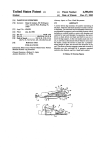
10 Claims, 6 Drawing Sheets
6/2
OPERATION
DETECTING
/
f 0
VEHICLE SPEED
DETECTING
fl‘,
DECELERATION
DETECTING
l
I is
20
ENGINE
._/
BRAKE DOWN
SHIFT
DEMANDED
A
IDLE STATE
DETECT‘NG
22
SHIFT
CONTROLLING
1
DELAY SETTING
AUTOMATIC
TRANSMISSION
OTHER KINDS
OF
INFORMATION
/-/8
,24
U.S. Patent
June 11, 1991
FIG-2b
FlG.2a
‘
‘
START )
\%
START
>
I
\
C=C+1
5,022,286
Sheet2of6
/-30
AC=C-C'
C'=C
\
RETURN
C=¢
\%
RETURN
f3?
US. Patent
June 11, 1991
FIG-3
40
NO
IS
BRAKE SW.
ON ?
READ
OFF
: VH
/—50
: VL
: ACSET
FDS=1
{
RETURN
>
Sheet 3 of 6
5,022,286
US. Patent
Juné 11, 1991
Sheet 4 of 6
5,022,286
FIG-4
I START I
READ
OPERATING
CONDITION
I!
TABLE LOOK-UP [62
SHIFT PATTERN
7
DATA TO
DETERMINE
GEAR
POSITION GP
64
FDS '2
No
YES
/'68
GP : GP - 1
56
r
SUBPROGRAM
/-70
FOR SHIFTING
PROCEDURE
I
ENGAGE
OVERRUNNING
CLUTCH
I RETURN I
.
/
SUBPROGRAM
FOR SHIFTING
PROCEDURE
"72
U.S. Patent
June 11, 1991
5,022,286
Sheet 5 of 6
FIG-5
/86
‘ RETURN )
US. Patent
June 11, 1991
FIG.7
V
/04
IS
BRAKE sw.
ON '2
OFF
READ :vn
/~/06
:VL
:ACSET
I08
//0
AC ; ACSET
( RETURN' )
NO
Sheet 6 of 6 '
5,022,286
5,022,286
1
2
detecting a power demand by a driver of the automo
tive vehicle;
releasing the automatic transmission from said engine
brake running with downshifted state upon expiration
SYSTEM FOR AND METHOD OF CONTROLLING
SHIFI'ING IN GEAR POSITION IN AUTOMATIC
TRANSMISSION
of a predetermined delay time after said power demand
has been detected unless said power demand disappears;
BACKGROUND OF THE INVENTION
releasing the automatic transmission from the engine
brake running with downshifted state immediately after
method of, controlling shifting in gear position in an
said power demand has disappeared.
automatic transmission, and more particularly to a sys 10
According to another aspect of the present invention,
tem for, and a method of controlling shifting in gear
there is provided a system for controlling shifting in
The present invention relates to a system for, and a
position in an automatic transmission when an automo
tive vehicle which the automatic transmission is
mounted on is subject to deceleration.
An automatic transmission of the E4N71B type is
known. This automatic transmission is manufactured by
Nissan Motor Company Limited in Japan and described
in a publication “NISSAN AUTOMATIC TRANS
MISSION L4N71B TYPE, E4N71B TYPE, SER
VICE MANUAL 1982 (A261CO4)” issued by Nissan
Motor Company Limited on November in 1982. This
known transmission comprises a downshift solenoid, a
gear position in an automatic transmission for an auto
motive vehicle when the vehicle is subjected to deceler
‘ation, wherein an engine brake running with down
shifted state is initiated when predetermined conditions
are met, the system comprising:
shift switch, an idle switch, a vehicle speed sensor, a
brake switch, and a control unit. As described on page
means for detecting a power demand by a driver of
the automotive vehicle; and
means for releasing the automatic transmission from
said engine brake running with downshifted state upon
expiration of a predetermined delay time after said
power demand has been detected.
According to still further aspect of the invention,
there is provided a system for controlling shifting in
12 of the above-mentioned publication, the downshift
gear position in an automatic transmission for an auto
solenoid is rendered ON when the shift switch indicates
that the third gear position is established in D range, the
vehicle speed sensor detects a vehicle speed falling in a
predetermined range from 30 km/h to 50 km/h, the
brake switch is rendered ON, and the idle contacts of
the throttle switch are rendered ON. According to this
motive vehicle when the vehicle is subjected to deceler
ation, wherein an engine brake running with down
shifted state is initiated when predetermined conditions
are met, the system comprising:
downshift control, the downshift solenoid is rendered
OFF to cause an upshift to take place in the automatic
transmission when the idle switch is rendered OFF in
response to the driver’s depressing of an accelerator
pedal. This abrupt upshift from the downshifted state
induces a shock and an unplesant ride feel or sensation
to the driver.
An object of the present invention, therefore, is to
provide a system for, and a method of, controlling the 40
gear position in an automatic transmission when an
automotive vehicle which the automatic transmission is
mounted on is subject to deceleration, which are im
proved such that the above-mentioned shock nor the
means for detecting a power demand by a driver of
the automotive vehicle; and
means for releasing the automatic transmission from
said engine brake running with downshifted state upon
expiration of a predetermined delay time after said
power demand has been detected unless said power
demand disappears, said releasing means being opera
tive to release the automatic transmission from the en
gine brake'running with downshifted state immediately
after said power demand has disappeared.
BRIEF DESCRIPTION OF THE DRAWINGS
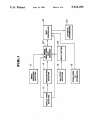
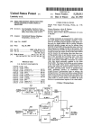
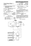
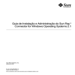
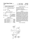
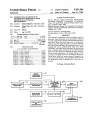
FIG. 1 is a functional block diagram of a first embodi
ment according to the present invention;
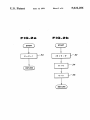
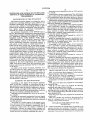
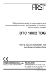
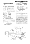
FIG. 2a is a flow chart of a program for counting a
neither unplesant ride feel encountered in the prior art 45 pulse generated by a vehicle speed sensor;
are eliminated or alleviated.
SUMMARY OF THE INVENTION
According to one aspect of the present invention,
there is provided a method of controlling shifting in
gear position in an automatic transmission for an auto
FIG. 2b is a flow chart of a program for determining
a deceleration to which an automotive vehicle is sub
jected;
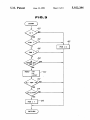
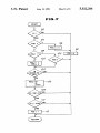
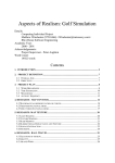
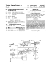
FIG. 3 is a flow chart of a program for controlling a
downshift ?ag;
'
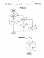
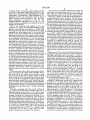
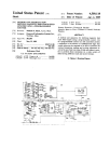
FIG. 4 is a flow chart of a program for effecting
downshift and engine brake running;
motive vehicle when the vehicle is subjected to deceler
FIG. 5 is a flow chart of a program for controlling a
ation, wherein an engine brake running with down
idle ?ag such that the idle flag is kept being set equal to
shifted state is initiated when predetermined conditions
55 1 for a predetermined delay time after an idle switch has
are met, the method comprising the steps of:
been rendered OFF;
detecting a power demand by a driver of the automo
FIG. 6 is a flow chart of a program for decrement of
tive vehicle;
releasing the automatic transmission from said engine
brake running with downshifted state upon expiration
of a predetermined delay time after said power demand
has been detected.
According to a further aspect of the present inven
tion, there is provided a method of controlling shifting
in gear position in an automatic transmission for an
automotive vehicle when the vehicle is subjected to 65
deceleration, wherein an engine brake running with
downshifted state is initiated when predetermined con
ditions are met, the method comprising the steps of:
a timer; and
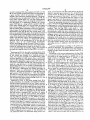
FIG. 7 is a similar view to FIG. 3, illustrating a flow
chart of a program used in a second embodiment ac~
cording to the present invention.
DETAILED DESCRIPTION OF THE
INVENTION
Before describing the embodiments according to the
present invention, an automatic transmission a which
the present invention is embodied or applied to is brie?y
described. This automatic transmission is manufactured
3
5,022,286
scribed in a publication “SERVICE MANUAL, NIS
SAN FULL RANGE ELECTRONICALLY CON
TROLLED AUTOMATIC TRANSMISSION OF
block 16 indicates that the idle switch is rendered OFF.
Referring to FIGS. 20 and 2b, the deceleration de
tecting block 14 is further described. This block has a
counter C which counts occurences of pulse signals
from the vehicle speed sensor. The execution of a pro
gram as shown by the How chart in FIG. 2a is initiated
RE4RO1A TYPE, 1987 (A261C07)” issued by Nissan
Motor Company Limited on March in 1987. This auto
matic transmission is disclosed in US Pat. No.
4,680,992 issued to Hayasaki et al. on July 21, 1987
which is hereby incorporated by references in this ap
plication in its entirety.
FIG. 1, is a functional block diagram of a ?rst em
bodiment of a system for controlling shifting in gear
position in an automatic transmission. A vehicle speed
4
The previously mentioned block 26 for setting the
delay gives the predetermined delay to the block 20
only when the output of the idle operation detecting
by Nissan Motor Company Limited in Japan and de
10
by interruption occurring in synchronism with the oc
currence of pulse signal from the vehicle speed sensor.
At a step 30, the content of the counter C is increased by
one. The execution of a program as illustrated in a flow
detecting block 10 counts the occurrences of a pulse
generated by a vehicle speed sensor for a predetermined
period of time (for example, 100 ms or 354 ms) and
generates the result as a vehicle speed indicative signal.
The vehicle speed sensor is provided on an output shaft
of an automatic transmission 24. A brake operation
detecting block 12 is provided where a brake signal
generated by a brake switch is detected and it is deter
mined whether the brake is operated or not. A decelera
tion detecting block 14 is provided where a derivative
of the vehicle speed indicative signal from the vehicle
‘chart in FIG. 2b is initiated upon expiration of a prede
termined period of time for example 100 ms or 354 ms.
At a step 32, a difference AC (delta C) is calculated by
speed detecting block 10 during a predetermined period
eration indicative signal may directly be given by the
of time is calculated and the result is outputted as a
deceleration indicative signal. Alternatively, the decel
eration which the vehicle is subject to can be directly
given by a deceleration sensor mounted to measure the
longitudinal deceleration which the vehicle is subject
to. An idle state detecting block 16 is provided where an
output signal of an idle switch is detected and it is deter
mined whether the engine throttle valve is at the idle
speed position or not. The idle switch is arranged within
the engine throttle chamber. A block 18 is provided
subtracting C’ from C, where C represents the present
content of the counter, while C’ the previous content of
the counter given the predetermined period of time ago.
At a step 34, C’ is updated and set equal to C. Then, at
a step 36, C is cleared and set equal to 0 (zero). The
difference AC (delta C) is negative when the vehicle is
subject to deceleration and thus variable with the decel
eration which the vehicle is subject to and thus used as
the deceleration indicative signal. Of course, the decel
vehicle mount deceleration sensor (or an accelerenome
ter).
Referring to FIG. 3, the block 20 for effecting down
shifting for engine brake running is further described. A
?ag FDS is provided which is set equal to 1 when the
predetermined conditions for effecting downshifting for
engine brake running are met. This flag FDS is called an
engine brake downshift demand ?ag. Theflag FDS is
set equal to 0 (zero) when the selector of a manual valve
is placed at D range position or an idle flag FIDL
where the other kinds of information, such as a throttle
(which is later described) is equal to 0 (zero) or the
opening degree and an oil temperature of oil used in the
brake switch is rendered OFF. The flag FDS is set
automatic transmission, which are necessary for the
equal to 1 when the selector is placed at the D range
shifting control are detected and generated as output 40 position and the idle ?ag FIDL is equal to l and the
signals.
brake switch is rendered ON and the vehicle speed VSP
There is provided a block 20 for determining whether
falls in a range greater than a lower limit vehicle speed
there is any demand for engine brake downshift. Fed to
VL but less than an upper limit vehicle speed VH and
this block 20 are the vehicle speed indicative signal
the deceleration AC (delta C) is less than or equal to a
from the block 10, the brake operation indicative signal 45 predetermined degree, i.e., ACéACSEzz where ACSET
from the block 12, the idle operation indicative signal
is a predetermined negative value.
from a block 26 accompanied by a delay, and the gear
Describing along the flow chart shown in FIG. 3, at
position indicative signal from a shift controlling block
a step 40, it is determined whether the D range position
22. At the block 20, it is determined whether predeter
is selected or not. When the D range position is not
mined conditions are met for effecting downshifting for
selected at the step 40, the program proceeds to a step
an engine brake running or not. The output of the block
42 where the ?ag FDS is set equal to 0 (zero) before the
20 indicative of the result is fed to the shift controlling
program comes to an end. When at the step 40 it is
block 22.
j
determined that D range position is selected, the pro
The shift controlling block 22 controls shifting in
gram proceeds to a step 44 where it is determined
gear position in the automatic transmission 24 in a con
whether an idle flag FIDL is set equal to l or not. When
ventional manner in the absence of the output signal
it is determined that the ?ag FIDL is set equal to 0, the
from the block 20 indicative of the fact that the prede
program proceeds to the above-mentioned step 42 be
termined conditions for effecting downshifting for en
fore the program comes to an end. When it is deter
gine brake running are met. However, upon receipt of
mined that the flag FIDL is set equal to l, the program
the output signal from the block 20 indicative of the fact 60 proceeds to a step 46 where it is determined whether the
that the predetermined conditions for effecting down
flag FDS is set equal to l or 0. When it is determined
shifting for engine brake running are met, the shift con
that the flag FDS is set equal to 1, the program comes
trolling block 22 commands downshifting and engaging
of a clutch for effecting engine brake running, such as
to an end. When it is determined at the step 46 that the
?ag FDS is set equal to 0, the program proceeds to a
an overrunning clutch in the case of the automatic 65 step 48 where it is determined whether the brake switch
is rendered ON or OFF. When it is determined that the
transmission disclosed in US. Pat. No. 4,680,992 issued
to Hayasaki et al. on July 21, 1987 which has been
brake switch is rendered OFF, the program comes to an
end. When it is determined at the step 48 that the brake
hereby incorporated in its entirety by reference.
5,022,286
5
switch is rendered ON, the program proceeds to a step
50. At the step 50, predetermined data corresponding to
a gear position which the automatic transmission is
6
gram as illustrated by the flow chart shown in FIG. 6
which is exected upon expiration of a predetermined
period of time. In FIG. 6, at a step 84 it is determined
shifted to are obtained by reading operation. The prede
whether the content of the timer T is equal to 0 (zero)
termined data are, the upper limit vehicle speed VH, the
lower limit vehicle speed VL, and the predetermined
or not. When it is determined that the content of the
timer is not equal to O, the program proceeds to a step
deceleration ACSET. Then, the program proceeds to a
step 52 where it is determined whether the vehicle
speed VSP falls in a range which is greater than the
lower limit vehicle speed VL but less than the upper
limit vehicle speed VH or not. When it is determined
that the vehicle speed VSP does not fall in the predeter
mined range, the program comes to an end. When it is
determined at the step 52 that the vehicle speed VSP
falls in the predetermined range, the program proceeds
to a step 54 where it is determined whether the absolute
value of the deceleration AC (delta C) is greater than or 7
equal to the absolute value of the predetermined decel
eration ACSET or not. When it is determined that the
absolute value of the deceleration AC is less than the
absolute value of the predetermined deceleration
ACSET, the program comes to an end. When it is deter
mined at the step 54 that the absolute value of the decel
eration AC is greater than or equal to the absolute value
of the predetermined deceleration ACSET, the program
proceeds to a step 56 where the flag FDS is set equal to
1.
Referring to FIG. 4, the shift controlling block 22 is
further described. At a step 60, the operating conditions
of the vehicle are obtained by a reading operation.
Then, the program proceeds to a step 62 where a table
86 where the content of timer T is decreased by 1 (one).
From the preceding description of the ?rst embodi
ment, it will now be appreciated that the idle flag FIDL
is kept equal to 1 until the predetermined delay time TD
is expired after the idle switch has been turned to OFF
position. Thus, the flag FDS is kept equal to 1 until
expiration of the predetermined delay time even after
the accelerator pedal has been depressued during the
engine brake running with the downshifted state and the
program comes to an end after proceeding along the
steps 40, 44, and 46 upon execution of each cycle until
expiration of this delay time. As a result, the automatic
transmission is prevented from upshifting immediately
afterthe accelerator pedal has been depressed during
the engine brake running with the downshifted state,
alleviating shock or unplesant ride feel given to the
driver.
. A-second embodiment according to the present in
vention is described. This embodiment is substantially
the same as the ?rst embodiment except the manner of
setting an engine brake downshift demand flag FDS at
a block 20.
According to this second embodiment, the flag FDS
look-up operation of shift pattern data is performed
is set equal to 0 when (the selector of a manual valve is
not placed at D range position) or (FIDL=O) or (the
brake switch is rendered OFF) or (FIDL-=l and
based on the operating conditions stored at the preced
ing step 60 to determine a gear position GP which the
automatic transmission should take. The program pro
FIDL1=O). The flag FDS is set equal to 1 when (the
selector is placed at the D range position) and
(FIDL: 1) and (the brake switch is rendered ON) and
ceeds to a step 64 where it is determined whether the
flag FDS is equal to l or not. When it is determined that
(the vehicle speed VSP falls in a range greater than a
lower limit vehicle speed VL but less than an upper
the flag FDS is equal to 0, the program proceeds to a
limit vehicle speed VH) and (the deceleration AC is less
than or equal to a predetermined deceleration ACSET).
Describing further along the ?ow chart shown in
step 66 where a subprogram for shifting procedure is
executed. When it is determined that the flag FDS is
equal to l, the program proceeds to a step 68 where the
gear position GP is decreased by 1. Then, the program
proceeds to a step 70 where the subprogram for shifting
procedure is executed. Then, the program proceeds to a
step 72 where the engine brake running clutch (i.e., the
overrunning clutch) is engaged.
Referring to FIG. 5, the delay setting block 26 is
further described. At a step 74, it is determiend whether
the idle switch is rendered ON or not. When it is deter
mined that the idle switch is rendered ON and thus the
engine throttle is at the idle speed position, the program
proceeds to a step 76 where the idle flag FIDL is set
equal to l and a timer is set equal to a predetermined
delay time TD. When it is determined at the step 74 that
the idle switch is rendered OFF and thus the engine
throttle is not at the idle speed position, the program
FIG. 7, at a step 90, it is determined whether the D
range position is selected or not. When the D range
position is not selected at the step 40, the program pro~
ceeds to a step 92 where the flag FDS is set equal to 0
(zero) before the program comes to an end. When at the
step 90 it is determined that D range position is selected
the program proceeds to a step 94 where it is deter
mined whether the flag FIDL is set equal to 1V or not.
When at the step 94 it is determined that the flag FIDL
is set equal to O, the program proceeds to a step 96
where a ?ag FIDLl is set equal to 0 and then to the
above-mentioned step 92 where the flag FDS is set
equal to 0. When at the step 94 it is determined that the
flag FDL is set equal to l, the program proceeds to a
step 98 where it is determined whether the flag FIDLl
is set equal to l or not. When ‘at the step 98 it is deter
mined that the ilag FIDLl is set equal to l, the program
proceeds to a step 78 where it is determined whether the
proceeds to a step 102 where it is determined whether
idle flag FIDL is equal to l or not. When it is deter
the ?ag FDS is set equal to l or 0. When at the step 102
mined that the idle flag FIDL is equal to l, the program
proceeds to a step 80 where it is determined whether the 60 it is determined that the flag FDS is set equal to l, the
program comes to an end. When at the step 102 it is
content of the timer T is equal to 0 (zero) or not. When
determined that the flag FDS is set equal to O, the pro
it is determined that the content of the timer T is not yet
gram proceeds to a step 104. When at the step 98 it is
reduced down to 0, the program comes to an end with
determined that ?ag FIDLl is set equal to O, the pro
out clearing the idle flag FIDL. When it is determined
at the step 80 that the content of the timer T is equal to 65 gram proceeds to a step 100 where the flag FIDLl is set
equal to l and the flag FDS is set equal to O and then to
0, the program proceeds to a step 82 where the idle ?ag
the step 104. From the preceding description of the flow
FIDL is cleared and set equal to 0. The decrement of
chart, it will now be noted that the flag FIDLI is set
the reduction timer T is performed along with a pro
7
5,022,286
equal to 0 immediately after the ?ag F IDL has been set
equal to 0 (see steps 94 and 96), while it is set equal to 1
immediately after the flag FIDL has been set equal to 1
(see steps 94, 98 and 100). Thus, the flag FIDLI is indic
ative of the state of the ?ag FIDL in the previous cycle
or run of the program. Thus, it will be appreciated that
the flag FDS is set equal to 0 when the idle switch is
rendered ON again after the idle switch has been ren
dered OFF. At the step 104, it is determined whether
8
4. A method of controlling shifting in gear position in
an automatic transmission for an automotive vehicle
when the vehicle is subjected to deceleration, wherein
the automatic transmission is downshifted and condi
tioned in engine brake running state after predetermined
conditions have been met, the predetermined conditions
including absence of a power demand by a driver of the
automotive vehicle, the method comprising the steps of:
determining whether or not there is a presence of said
the brake switch is ON or OFF. When it is determined
power demand after the predetermined conditions
that the brake switch is rendered OFF, the program
have been met;
comes to an end. When it is determined at the step 104
that the brake switch is rendered ON, the program
proceeds to a step 106. At the step 106, predetermined
data corresponding to a gear position which the auto
matic transmission is shifted to are obtained by reading
operation. The predetermined data are, the upper limit
vehicle speed VI-I, the lower limit vehicle speed VL,
and the predetermined deceleration ACSET. Then, the
program proceeds to a step 108 where it is determined
whether the vehicle speed VSP falls in a range which is
greater than the lower limit vehicle speed VL but less
than the upper limit vehicle speed VH or not. When it
is determined that the vehicle speed VSP does not fall in
the predetermined range, the program comes to an end.
When it is determined at the step 108 that the vehicle
speed VSP falls in the predetermined range, the pro
'
releasing the automatic transmission from the engine
brake running state upon expiration of a predeter
mined delay time beginning with determination of
the presence of the power demand by said deter
mining step as long as the presence of said power
demand is kept determined during said predeter
mined time delay; and
releasing the automatic transmission from the engine
brake running state upon determination of the ab
sence of the power demand by said determining
step before expiration of said predetermined time
delay.
5. A method as claimed in claim 4, wherein said
power demand is detected when a throttle is opened.
6. A method as claimed in claim 5, wherein the open
ing of said throttle is detected when an idle switch is
rendered OFF.
gram proceeds to a step 110 where it is determined
7. A system for controlling shifting in gear position in
whether the deceleration AC (delta C) is less than or 30 an automatic transmission for an automotive vehicle
equal to the predetermined deceleration ACSET or not.
when the vehicle is subjected to deceleration, wherein
When it is determined that the absoulte value of the
the automatic transmission is downshifted and condi
deceleration AC is less than the absolute value of the
tioned in engine brake running state after predetermined
predetermined deceleration ACSET, the program comes
conditions have been met, the predetermined conditions
to an end. When it is determined at the step 110 that the
including absence of a power demand by a driver of the
absolute value of the deceleration AC is greater than or
automotive vehicle, the system comprising:
equal to the absolute value of the predetermined decel-v
means for detecting the power demand; and
eration ACSET, the program proceeds to a step 112
control means for determining whether or not the
where the flag FDS is set equal to 1.
From the above description of the second embodi
ment, it will be noted that during the period when the
release of the engine brake running with the down
shifted state is delayed, this brake running with down
shifted state is released and an upshift takes place imme
power demand is detected after the predetermined
conditions have been met and then releasing the
automatic transmission from the engine brake run
ning state upon expiration of a predetermined delay
time beginning with the detection of the power
demand after the predetermined conditions have
diately when the accelerator pedal is released again 45
been met.
’
after it has been depressed.
8. A system for controlling shifting in gear position in
What is claimed is:
- an automatic transmission for an automotive vehicle
1. A method of controlling shifting in gear position in
when the vehicle is subjected to deceleration, wherein
an automatic transmission for an automotive vehicle
the automatic transmission is downshifted and condi
when the vehicle is subjected to deceleration, wherein 50 tioned in engine brake running state after predetermined
the automatic transmission is downshifted and condi
conditions have been met, the system comprising:
tioned in engine brake running state after predetermined
means for detecting the power demand; and
conditions have been met, the predetermined conditions
control means for determining whether or not the
including absence of a power demand by a driver of the
power demand is detected after the predetermined
automotive vehicle, the method comprising the steps of:
conditions have been met and then releasing the
determining whether or not there is a presence of the
automatic transmission form the engine brake run
power demand after the predetermined conditions
ning state upon expiration of a predetermined delay
have been met; and
time beginning with the detection of the power
releasing the automatic transmission from the engine
demand as long as the presence of the power de
brake running state upon expiration of a predeter 60
mined delay time beginning with determination of
the presence of the power demand by said deter
mand is kept determined during said predetermined
time delay, said the control means being operative
mining step.
gine brake running state upon determination of the
absence of the power demand before expiration of
to release the automatic transmission from the en
2. A method as claimed in claim 1, wherein said
power demand is detected when a throttle is opened. 65
said predetermined time delay.
9. A method of controlling shifting in gear position in
3. A method as claimed in claim 2, wherein the open
ing of said throttle is detected when an idle switch is
an automatic transmission for an automotive vehicle,
the method comprising the steps of:
rendered OFF.
9
5,022,286
determining one gear position;
determining whether predetermined conditions are
met or not, said predetermined conditions includ
ing absence of a power demand by a driver of the
automotive vehicle;
met or not, said predetermined conditions includ
ing the absence of a power demand by a driver of
5
conditioning the automatic transmission at another
gear position lower than said one gear position and
in engine brake running state after it has been deter
mined that said predetermined conditions are met; 10
detecting the presence of said power demand; and
conditioning the automatic transmission at said one
gear position and releasing the automatic transmis
sion from said engine brake running state upon
expiration of a predetermined delay time beginning
10
determining whether predetermined conditions are
15
the automotive vehicle;
detecting the presence of said power demand;
conditioning the automatic transmission at another
gear position lower than said one gear position and
in engine brake running state when it is determined
that said predetermined conditions are met;
conditioning the automatic transmission at said one
gear position and releasing the automatic transmis
sion from said engine brake running state upon
expiration of a predetermined delay time beginning
with detection of the presence of said power de
mand as long as the presence of said power demand
remains detected during said predetermined delay
time; and
with detection of presence of said power demand
after it has been determined that said predetemined
conditioning the automatic transmission at said one
conditions are met.
10. A method of controlling shifting in gear position
gear position and releasing the automatic transmis
sion from said engine brake running state upon
in an automatic transmission for an automotive vehicle,
absence of said power demand before expiration of
the method comprising the steps of:
determining one gear position;
said predetermined delay time.
it
25
30
35
45
65
t
it
*
t