1
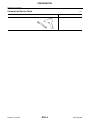
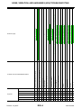
E SUSPENSION
A
B
SECTION
REAR SUSPENSION
C
D
RSU
CONTENTS
PRECAUTIONS .......................................................... 3
Precautions for Supplemental Restraint System
(SRS) “AIR BAG” and “SEAT BELT PRE-TENSIONER” .................................................................. 3
Precautions for Rear Suspension ............................ 3
PREPARATION ........................................................... 4
Commercial Service Tools ........................................ 4
NOISE, VIBRATION, AND HARSHNESS (NVH)
TROUBLESHOOTING ................................................ 5
NVH Troubleshooting Chart ..................................... 5
CAN COMMUNICATION ............................................ 7
System Description .................................................. 7
TROUBLE DIAGNOSIS .............................................. 8
How to Perform Trouble Diagnoses for Quick and
Accurate Repair ....................................................... 8
INTRODUCTION ................................................... 8
CLARIFY CONCERN ............................................ 8
WORK FLOW ........................................................ 9
Component Parts and Harness Connector Location... 10
Wiring Diagram — A/SUSP — ................................11
Basic Inspection ..................................................... 13
AIR HOSES ......................................................... 13
POWER SYSTEM TERMINAL LOOSENESS
AND BATTERY INSPECTION ............................ 13
CK SUSP INDICATOR LAMP INSPECTION ...... 13
CK SUSP Indicator Lamp Timing ........................... 13
Control Unit Input/Output Signal Standard ............. 13
CONSULT-II Function (AIR LEVELIZER) ............... 14
CONSULT-II START PROCEDURE .................... 14
SELF-DIAGNOSIS .............................................. 14
WORK SUPPORT ............................................... 15
DATA MONITOR ................................................. 15
ACTIVE TEST ..................................................... 15
TROUBLE DIAGNOSIS FOR SELF-DIAGNOSTIC
ITEMS ....................................................................... 16
Height Sensor System Inspection .......................... 16
Exhaust Valve Solenoid System Inspection ........... 17
Compressor Motor, Compressor Motor Relay and
Revision: July 2007
Circuit Inspection .................................................... 19
TROUBLE DIAGNOSES FOR SYMPTOMS ............ 22
Load Leveling Rear Air Suspension System Does
Not Operate ............................................................ 22
CK SUSP Indicator Lamp Stays On When Ignition
Switch Is Turned On ............................................... 23
REAR SUSPENSION ASSEMBLY ........................... 24
Components ........................................................... 24
On-Vehicle Inspection and Service ......................... 25
SHOCK ABSORBER INSPECTION (WITH AND
WITHOUT THE AIR LEVELING SYSTEM) ......... 25
Wheel Alignment Inspection ................................... 26
PRELIMINARY INSPECTION ............................. 26
GENERAL INFORMATION AND RECOMMENDATIONS ............................................................. 26
THE ALIGNMENT PROCESS ............................. 27
CAMBER ............................................................. 27
TOE-IN ................................................................ 27
REAR SUSPENSION MEMBER ............................... 29
Removal and Installation ........................................ 29
REMOVAL ........................................................... 30
INSPECTION AFTER REMOVAL ....................... 31
INSTALLATION ................................................... 32
SHOCK ABSORBER ................................................ 33
Removal and Installation ........................................ 33
REMOVAL ........................................................... 33
INSTALLATION ................................................... 33
Inspection ............................................................... 33
SUSPENSION ARM .................................................. 34
Removal and Installation ........................................ 34
REMOVAL ........................................................... 34
INSPECTION AFTER REMOVAL ....................... 34
INSTALLATION ................................................... 35
FRONT LOWER LINK .............................................. 36
Removal and Installation ........................................ 36
REMOVAL ........................................................... 36
INSPECTION AFTER REMOVAL ....................... 36
INSTALLATION ................................................... 37
RSU-1
2007 Armada
F
G
H
I
J
K
L
M
REAR LOWER LINK & COIL SPRING ..................... 38
Removal and Installation ........................................ 38
REMOVAL ........................................................... 38
INSPECTION AFTER REMOVAL ........................ 39
INSTALLATION .................................................... 39
STABILIZER BAR ..................................................... 40
Removal and Installation ........................................ 40
REMOVAL ........................................................... 40
INSPECTION AFTER REMOVAL ........................ 40
INSTALLATION .................................................... 40
REAR LOAD LEVELING AIR SUSPENSION COMPRESSOR ASSEMBLY ............................................ 41
Removal and Installation ........................................ 41
REMOVAL ........................................................... 41
INSTALLATION .................................................... 42
Revision: July 2007
HEIGHT SENSOR .....................................................43
Removal and Installation .........................................43
REMOVAL ............................................................43
INSTALLATION ....................................................44
CONTROL UNIT ........................................................45
Removal and Installation .........................................45
REMOVAL ............................................................45
INSTALLATION ....................................................45
Initialization Procedure ............................................45
SERVICE DATA AND SPECIFICATIONS (SDS) ......46
Wheel Alignment (Unladen*1 ) ................................46
Ball Joint .................................................................46
Wheelarch Height (Unladen*1 ) ...............................47
RSU-2
2007 Armada
PRECAUTIONS
PRECAUTIONS
PFP:00001
Precautions for Supplemental Restraint System (SRS) “AIR BAG” and “SEAT
BELT PRE-TENSIONER”
A
EES002HG
The Supplemental Restraint System such as “AIR BAG” and “SEAT BELT PRE-TENSIONER”, used along B
with a front seat belt, helps to reduce the risk or severity of injury to the driver and front passenger for certain
types of collision. This system includes seat belt switch inputs and dual stage front air bag modules. The SRS
system uses the seat belt switches to determine the front air bag deployment, and may only deploy one front C
air bag, depending on the severity of a collision and whether the front occupants are belted or unbelted.
Information necessary to service the system safely is included in the SRS and SB section of this Service Manual.
D
WARNING:
●
To avoid rendering the SRS inoperative, which could increase the risk of personal injury or death
in the event of a collision which would result in air bag inflation, all maintenance must be performed by an authorized NISSAN/INFINITI dealer.
RSU
●
Improper maintenance, including incorrect removal and installation of the SRS, can lead to personal injury caused by unintentional activation of the system. For removal of Spiral Cable and Air
Bag Module, see the SRS section.
F
●
Do not use electrical test equipment on any circuit related to the SRS unless instructed to in this
Service Manual. SRS wiring harnesses can be identified by yellow and/or orange harnesses or
harness connectors.
G
Precautions for Rear Suspension
●
●
●
●
EES002HH
When installing the rubber bushings, the final tightening must be done under unladen condition and with
the tires on level ground. Oil will shorten the life of the rubber bushings, so wipe off any spilled oil immediately.
Unladen condition means the fuel tank, engine coolant and lubricants are at the full specification. The
spare tire, jack, hand tools, and mats are in their designated positions.
After installing suspension components, check the wheel alignment.
Caulking nuts are not reusable. Always use new caulking nuts for installation. New caulking nuts are preoiled, do not apply any additional lubrication.
H
I
J
K
L
M
Revision: July 2007
RSU-3
2007 Armada
PREPARATION
PREPARATION
Commercial Service Tools
PFP:00002
EES002HI
Tool name
Description
Power tool
Removing nuts and bolts
PBIC0190E
Revision: July 2007
RSU-4
2007 Armada
NOISE, VIBRATION, AND HARSHNESS (NVH) TROUBLESHOOTING
NOISE, VIBRATION, AND HARSHNESS (NVH) TROUBLESHOOTING
NVH Troubleshooting Chart
PFP:00003
A
EES002HJ
Use chart below to help you find the cause of the symptom. If necessary, repair or replace these parts.
B
C
D
RSU
F
G
H
I
J
K
L
M
Revision: July 2007
RSU-5
2007 Armada
—
×
×
×
Shake
×
×
×
×
Vibration
×
×
×
×
Shimmy
×
×
×
×
Shudder
×
×
×
Poor quality ride or handling
×
×
×
Revision: July 2007
×
RSU-6
×
×
×
×
×
RSU-24, "Components"
PR-3, "NOISE, VIBRATION, AND HARSHNESS (NVH) TROUBLESHOOTING"
RFD-7, "NVH Troubleshooting Chart"
FSU-4, "NVH Troubleshooting Chart"
WT-4, "NVH Troubleshooting Chart"
WT-4, "NVH Troubleshooting Chart"
WT-4, "NVH Troubleshooting Chart"
PR-3, "NVH Troubleshooting Chart"
BR-5, "NVH Troubleshooting Chart"
PS-5, "NVH Troubleshooting Chart"
PROPELLER SHAFT
DIFFERENTIAL
FRONT SUSPENSION
FRONT AXLE
TIRES
ROAD WHEEL
DRIVE SHAFT
BRAKES
STEERING
RSU-26, "Wheel Alignment Inspection"
RSU-24, "Components"
Stabilizer bar fatigue
Incorrect wheel alignment
Suspension looseness
—
Parts interference
×
Spring fatigue
—
Noise
RSU-25, "SHOCK ABSORBER INSPECTION (WITH AND WITHOUT THE AIR LEVELING SYSTEM)"
Bushing or mounting deterioration
Possible cause and SUSPECTED PARTS
Shock absorber deformation, damage or deflection
Symptom
RSU-24, "Components"
Reference page
Improper installation, looseness
NOISE, VIBRATION, AND HARSHNESS (NVH) TROUBLESHOOTING
×
×
×
×
×
×
×
×
×
×
×
×
×
×
×
×
×
×
×
×
×
×
×
×
×
×
×
×
×
×
×
×
×
×
×
×
×: Applicable
2007 Armada
CAN COMMUNICATION
CAN COMMUNICATION
System Description
PFP:23710
A
EES002HK
Refer to LAN-4, "CAN Communication System" .
B
C
D
RSU
F
G
H
I
J
K
L
M
Revision: July 2007
RSU-7
2007 Armada
TROUBLE DIAGNOSIS
TROUBLE DIAGNOSIS
How to Perform Trouble Diagnoses for Quick and Accurate Repair
PFP:00000
EES002HL
INTRODUCTION
The rear load leveling air suspension system uses an electronic control unit to control major functions. The control unit accepts input signals from the height sensor and controls compressor and exhaust
valve operation.
It is much more difficult to diagnose a rear load leveling air suspension system problem that occurs intermittently rather than continuously. Most intermittent problems are caused by poor electrical
connections or faulty wiring. In this case, careful checking of suspicious circuits may help prevent the replacement of good parts.
SEF233G
Before undertaking actual checks, take just a few minutes to talk with
a customer who approaches with an air suspension system complaint. The customer is a very good source of information on such
problems, especially intermittent ones. Through discussion with the
customer, find out what symptoms are present and under what conditions they occur.
Start your diagnosis by looking for basic mechanical problems first.
This is one of the best ways to troubleshoot concerns on an air suspension system equipped vehicle. Also check related Service Bulletins for information.
SEF234G
CLARIFY CONCERN
●
●
A customer's description of a vehicle concern may vary depending on the individual. It is important to clarify the customer's concern.
Ask the customer about what symptoms are present under what
conditions. Use this information to reproduce the symptom.
SBR339B
Revision: July 2007
RSU-8
2007 Armada
TROUBLE DIAGNOSIS
WORK FLOW
A
B
C
D
RSU
F
G
H
I
J
K
L
M
WEIA0077E
Revision: July 2007
RSU-9
2007 Armada
TROUBLE DIAGNOSIS
Component Parts and Harness Connector Location
EES002HM
WEIA0149E
:
Front
1.
Fuse Block (J/B)
2.
Fuse and fusible link box
4.
Suspension air compressor and
compressor motor relay C9
5.
Height sensor C8 (View from under 6.
vehicle)
Combination meter M24
7.
Generator E205
(View from under vehicle)
8.
Suspension air compressor motor
relay E130 (view with battery
removed)
Suspension air compressor motor
relay E131
Revision: July 2007
RSU-10
3.
9
Suspension control unit B3 (View
with upper and lower luggage side
finishers LH removed)
2007 Armada
TROUBLE DIAGNOSIS
Wiring Diagram — A/SUSP —
EES002HN
A
B
C
D
RSU
F
G
H
I
J
K
L
M
WEWA0053E
Revision: July 2007
RSU-11
2007 Armada
TROUBLE DIAGNOSIS
WEWA0069E
Revision: July 2007
RSU-12
2007 Armada
TROUBLE DIAGNOSIS
Basic Inspection
EES002HO
A
AIR HOSES
1.
2.
Check for pinched or damaged air hoses between the suspension air reservoir and each load leveling rear
air suspension shock absorber. Reposition, repair or replace hoses as necessary.
Check the air hose connections at the suspension air reservoir and at the shock absorbers for leaks. If
connections are leaking, repair or replace hoses as necessary.
POWER SYSTEM TERMINAL LOOSENESS AND BATTERY INSPECTION
Make sure the battery positive cable, negative cable and ground connection are not loose. In addition, make
sure the battery is sufficiently charged.
B
C
CK SUSP INDICATOR LAMP INSPECTION
1.
2.
3.
D
Make sure the CK SUSP indicator lamp turns on for approximately 2 seconds when the ignition switch is
turned ON. If it does not, check the combination meter. Refer to DI-5, "COMBINATION METERS" .
Make sure the lamp turns off approximately 2 seconds after the ignition switch is turned ON. If the lamp RSU
does not turn off, conduct self-diagnosis of the suspension control unit. Refer to RSU-14, "CONSULT-II
Function (AIR LEVELIZER)" .
After conducting the self-diagnosis, be sure to erase the error memory. Refer to RSU-14, "CONSULT-II
F
Function (AIR LEVELIZER)" .
CK SUSP Indicator Lamp Timing
EES002HP
G
CK SUSP
indicator lamp
Remarks
Ignition switch OFF
–
–
Ignition switch ON
X
Condition
H
Turns off after approximately 2 seconds.
X: ON
—: OFF
I
Control Unit Input/Output Signal Standard
EES002HQ
Terminal
No.
Wire color
1
V
Compressor relay output
3
W
Height sensor signal input
5
R
Reference voltage
6
G/R
Ignition power
7
W/L
Battery power
8
G/W
Diagnostic K-line
9
SB
Exhaust valve output
10
BR
Warning lamp
—
—
14
L
Height sensor ground
—
—
15
BR/W
16
B
Revision: July 2007
Item
Generator L signal input
Condition
Voltage (V)
(Approx.)
J
Battery voltage
Ignition switch ON or START
0.2V - 4.8V
K
5V
Battery voltage
—
—
Ignition switch ON or START
Engine running
Suspension control unit ground
—
RSU-13
L
—
Battery voltage
—
0V
2007 Armada
M
TROUBLE DIAGNOSIS
CONSULT-II Function (AIR LEVELIZER)
EES002HR
CONSULT-II can display each diagnostic item using the diagnostic test modes shown following.
AIR LEVELIZER
diagnostic mode
Description
WORK SUPPORT
Supports inspections and adjustments. Commands are transmitted to the suspension control unit for
setting the status suitable for required operation, input/output signals are received from the suspension control unit and received data is displayed.
SELF-DIAG RESULTS
DATA MONITOR
ACTIVE TEST
ECU PART NUMBER
Displays suspension control unit self-diagnosis results.
Displays suspension control unit input/output data in real time.
Operation of electrical loads can be checked by sending drive signal to them.
Suspension control unit part number can be read.
CONSULT-II START PROCEDURE
Refer to GI-38, "CONSULT-II Start Procedure" .
SELF-DIAGNOSIS
Display Item List
Self-diagnostic item
Vehicle height sensor
[C1801]
Compressor relay
[C1802]
Exhaust solenoid
[C1803]
Malfunction detecting condition
Check system
Vehicle height sensor voltage is less than 0.2V or greater than
4.8V for more than 60 seconds.
Refer to RSU-16, "Height
Sensor System Inspection" .
1. Driving transistor for compressor relay is off and monitor voltage continues high level for more than 10 seconds.
Refer to RSU-19, "Compressor Motor, Compressor
Motor Relay and Circuit
Inspection" .
2. Driving transistor for compressor relay is on and monitor voltage continues low level for more than 5 seconds.
1. Driving transistor for exhaust solenoid is off and monitor voltage continues high level for more than 10 seconds.
2. Driving transistor for exhaust solenoid is on and monitor voltage continues low level for more than 5 seconds.
Refer to RSU-17, "Exhaust
Valve Solenoid System
Inspection" .
Vehicle height adjusting trouble
(compressor)
[C1804]
Continuous compressor relay ON time is more than 120 seconds.
Refer to RSU-19, "Compressor Motor, Compressor
Motor Relay and Circuit
Inspection" .
Vehicle height adjusting trouble
(exhaust solenoid)
[C1805]
Continuous exhaust solenoid ON time is more than 120 seconds.
Refer to RSU-17, "Exhaust
Valve Solenoid System
Inspection" .
Vehicle height sensor locking trouble
[C1806]
Output sensor voltage variation ±0.02V is more than 100 hour
when vehicle height range is normal.
Refer to RSU-16, "Height
Sensor System Inspection" .
Sensor 5V trouble
[C1807]
Sensor reference voltage is less than 0.8V or more than 6V for
20 seconds.
Refer to RSU-16, "Height
Sensor System Inspection" .
Integral time trouble by supplying
air
[C1808]
Integral discontinuous time on the compressor is more than 180
seconds.
Refer to RSU-19, "Compressor Motor, Compressor
Motor Relay and Circuit
Inspection" .
Revision: July 2007
RSU-14
2007 Armada
TROUBLE DIAGNOSIS
WORK SUPPORT
Display Item List
A
Item
Description
Condition
Vehicle unladen RSU-47, "Wheelarch Height
STANDARD HEIGHT LEVEL
Resets the vehicle height to the initialization flag
setting stored in the suspension control unit.
NOTE:
Do not take your eyes off the vehicle while
CONSULT-II is processing.
Vehicle unladen RSU-47, "Wheelarch Height
ADJUST HEIGHT INI
CLEAR HEIGHT INI
Sets the height initialization flag in the suspension
control unit when the control unit has been replaced
or when the initialization flag has been cleared
using the "CLEAR HEIGHT INI" procedure.
Clears the initialization flag in the suspension control unit.
B
(Unladen*1 )" , set in a horizontal position and
not moving.
(Unladen*1 )" . Move vehicle forward and
backward approx. 5 m (16.4 ft.) and rock vehicle from side to side.
NOTE:
Do not move vehicle while CONSULT-II is processing.
Vehicle unladen RSU-47, "Wheelarch Height
(Unladen*1 )" .
DATA MONITOR
Display Item List
C
D
RSU
F
G
Data monitor item selection
Test Item
ALL
SIGNALS
SELECTION
FROM MENU
HEIGT SEN
X
X
HEIGT CALC
X
X
SEN FIX TIME
X
X
HEIGT INI VAL
X
X
COMPRESSOR
X
X
EXH SOLENOID
X
X
ACG L
X
X
H
I
J
K
X: Applicable
–: Not applicable
L
ACTIVE TEST
CAUTION:
●
Do not perform active test while driving.
M
Display Item List
Test Item
Description
COMPRESSOR
OFF/ON
EXHAUST SOLENOID
OFF/ON
WARNING LAMP
OFF/ON
CAUTION:
The "COMPRESSOR" active test will remain ON until it is turned off using CONSULT-II. Allowing the
compressor to run for an extended period of time may cause damage to air suspension system components due to excessive pressure in the air suspension system.
NOTE:
●
"TEST IS STOPPED" is displayed approximately 10 seconds after operation starts for all active test items
except "COMPRESSOR".
●
After "TEST IS STOPPED" is displayed, to perform test again, repeat Step 6.
Revision: July 2007
RSU-15
2007 Armada
TROUBLE DIAGNOSIS FOR SELF-DIAGNOSTIC ITEMS
TROUBLE DIAGNOSIS FOR SELF-DIAGNOSTIC ITEMS
Height Sensor System Inspection
PFP:00000
EES002HS
INSPECTION PROCEDURE
1. SELF-DIAGNOSIS RESULT CHECK
Check self-diagnosis results.
Self-diagnosis results
C1801
C1806
C1807
Is the above displayed in the self-diagnosis display items?
YES >> GO TO 3.
NO
>> GO TO 2.
2. DATA MONITOR CHECK
Conduct data monitor of "HEIGT SEN" to check if the status is normal.
HEIGT SEN
0.2V - 4.8V
OK or NG
OK
>> Inspection End.
NG
>> GO TO 3.
3. CONNECTOR INSPECTION
1. Disconnect suspension control unit connector B3 and height sensor C8.
2. Check the terminals for deformation, disconnection, looseness or damage.
OK or NG
OK
>> GO TO 4.
NG
>> Repair or replace as necessary.
4. CHECK HEIGHT SENSOR POWER
1.
2.
3.
Reconnect the suspension control unit connector.
Turn the ignition switch ON.
Check voltage between height sensor connector C8 terminal 1
and ground.
Voltage
: Approx. 5V
OK or NG
OK
>> GO TO 5.
NG
>> Check harness or connector for open or short. If OK,
replace suspension control unit. Refer to RSU-45,
"CONTROL UNIT" .
WEIA0084E
Revision: July 2007
RSU-16
2007 Armada
TROUBLE DIAGNOSIS FOR SELF-DIAGNOSTIC ITEMS
5. CHECK HEIGHT SENSOR GROUND
1.
2.
A
Turn ignition switch OFF.
Check continuity between height sensor connector C8 terminal
3 and ground.
3 - Ground
B
Continuity should exist.
OK or NG
OK
>> GO TO 6.
NG
>> Repair harness or connector.
C
D
WEIA0085E
RSU
6. CHECK HEIGHT SENSOR SIGNAL CIRCUIT
1.
2.
Disconnect suspension control unit connector.
Check continuity between height sensor connector C8 terminal
2 and suspension control unit connector B3 terminal 3.
2-3
F
Continuity should exist.
G
H
I
WEIA0086E
3.
Check continuity between height sensor connector C8 terminal
2 and ground.
2 - Ground
J
Continuity should not exist.
K
OK or NG
OK
>> Replace the height sensor. Refer to RSU-43, "HEIGHT
SENSOR" .
NG
>> Repair harness or connector.
L
WEIA0087E
Exhaust Valve Solenoid System Inspection
EES002HT
INSPECTION PROCEDURE
1. SELF-DIAGNOSIS RESULT CHECK
Check self-diagnosis results.
Self-diagnosis results
C1803
C1805
Is the above displayed in the self-diagnosis display items?
YES >> If code C1803 was retrieved during self-diagnosis, GO TO 3. If code C1805 was retrieved during
self-diagnosis, GO TO 2.
NO
>> Inspection End.
Revision: July 2007
RSU-17
2007 Armada
M
TROUBLE DIAGNOSIS FOR SELF-DIAGNOSTIC ITEMS
2. CHECK SYSTEM OPERATION
1.
Load vehicle to standard laden condition (with driver, front passenger, 2 passengers in second row seats
and no cargo).
2. Conduct active test of "COMPRESSOR" to raise vehicle ride height to +20mm.
CAUTION:
The "COMPRESSOR" active test will remain ON until it is turned off using CONSULT-II. Allowing
the compressor to run for an extended period of time may cause damage to air suspension system components due to excessive pressure in the air suspension system.
3. Return the rear load leveling air suspension system to normal operating mode.
4. Check self-diagnostic results.
Is code C1805 displayed again?
YES >> GO TO 3.
NO
>> Inspection End.
3. CONNECTOR INSPECTION
1. Turn ignition switch OFF.
2. Disconnect suspension control unit connector B3 and suspension air compressor C9.
3. Check the terminals for deformation, disconnection, looseness or damage.
OK or NG
OK
>> If code C1805 was retrieved during self-diagnosis, GO TO 4. If code C1803 was retrieved during
self-diagnosis, GO TO 6.
NG
>> Repair or replace as necessary.
4. AIR HOSE INSPECTION
Inspect for pinched or damaged air hoses between the suspension air reservoir and each load leveling rear air
suspension shock absorber.
OK or NG
OK
>> GO TO 5.
NG
>> Repair or replace as necessary.
5. EXHAUST VALVE SOLENOID INSPECTION
Apply 12V to suspension air compressor terminal 2 and ground to
suspension air compressor terminal 1.
System air pressure should vent.
OK or NG
OK
>> GO TO 6.
NG
>> Replace the suspension air compressor. Refer to RSU41, "REAR LOAD LEVELING AIR SUSPENSION COMPRESSOR ASSEMBLY" .
WEIA0063E
Revision: July 2007
RSU-18
2007 Armada
TROUBLE DIAGNOSIS FOR SELF-DIAGNOSTIC ITEMS
6. CHECK EXHAUST VALVE SOLENOID POWER AND GROUND
1.
2.
3.
A
Reconnect the suspension control unit connector.
Turn the ignition switch ON.
Check voltage between suspension air compressor connector
C9 terminal 2 and ground.
Voltage
B
: Approx. 12V
C
D
WEIA0088E
4.
5.
Turn ignition switch OFF.
Check continuity between suspension air compressor connector
C9 terminal 1 and ground.
1 - Ground
F
Continuity should exist.
G
OK or NG
OK
>> Replace the suspension control unit. Refer to RSU-45,
"CONTROL UNIT" .
NG
>> Repair harness or connector.
H
WEIA0089E
Compressor Motor, Compressor Motor Relay and Circuit Inspection
RSU
I
EES002HU
J
INSPECTION PROCEDURE
1. SELF-DIAGNOSIS RESULT CHECK
K
Check self-diagnosis results.
Self-diagnosis results
C1802
L
C1804
C1808
Is the above displayed in the self-diagnosis display items?
YES >> If code C1802 was retrieved during self-diagnosis, GO TO 3. If code C1804 or C1808 was
retrieved during self-diagnosis, GO TO 2.
NO
>> Inspection End.
2. CHECK SYSTEM OPERATION
1.
Load vehicle to standard laden condition (with driver, front passenger, 2 passengers in second row seats
and no cargo).
2. Conduct active test of "EXHAUST SOLENOID" to lower vehicle ride height to -20mm.
3. Return the rear load leveling air suspension system to normal operating mode.
4. Check self-diagnostic results.
Is code C1804 or C1808 displayed again?
YES >> GO TO 3.
NO
>> Inspection End.
Revision: July 2007
RSU-19
2007 Armada
M
TROUBLE DIAGNOSIS FOR SELF-DIAGNOSTIC ITEMS
3. CONNECTOR INSPECTION
1. Turn ignition switch OFF.
2. Disconnect suspension control unit connector B3 and suspension air compressor C9.
3. Check the terminals for deformation, disconnection, looseness or damage.
OK or NG
OK
>> If code C1804 or C1808 was retrieved during self-diagnosis, GO TO 4. If code C1802 was
retrieved during self-diagnosis, GO TO 6.
NG
>> Repair or replace as necessary.
4. AIR HOSE INSPECTION
Inspect for pinched or damaged air hoses between the suspension air reservoir and each load leveling rear air
suspension shock absorber.
OK or NG
OK
>> GO TO 5.
NG
>> Repair or replace as necessary.
5. SUSPENSION AIR COMPRESSOR INSPECTION
Apply 12V to suspension air compressor terminal 2 and ground to
suspension air compressor terminal 1.
System air pressure should vent.
OK or NG
OK
>> GO TO 6.
NG
>> Replace the suspension air compressor. Refer to RSU41, "REAR LOAD LEVELING AIR SUSPENSION COMPRESSOR ASSEMBLY" .
WEIA0066E
Revision: July 2007
RSU-20
2007 Armada
TROUBLE DIAGNOSIS FOR SELF-DIAGNOSTIC ITEMS
6. CHECK SUSPENSION AIR COMPRESSOR POWER AND GROUND
1.
2.
3.
A
Connect suspension control unit connector B3.
Turn the ignition switch ON.
Check voltage between suspension air compressor connector
C9 terminal 2 and ground.
Voltage
B
: Approx. 12V
C
D
WEIA0090E
4.
5.
Turn ignition switch OFF.
Check continuity between suspension air compressor connector
C9 terminal 1 and ground.
1 - Ground
RSU
F
Continuity should exist.
G
OK or NG
OK
>> Replace the suspension control unit. Refer to RSU-45,
"CONTROL UNIT" .
NG
>> Repair harness or connector.
H
WEIA0091E
I
J
K
L
M
Revision: July 2007
RSU-21
2007 Armada
TROUBLE DIAGNOSES FOR SYMPTOMS
TROUBLE DIAGNOSES FOR SYMPTOMS
Load Leveling Rear Air Suspension System Does Not Operate
PFP:99999
EES002HV
1. CHECK WARNING LAMP ACTIVATION
Make sure warning lamp remains off while driving.
OK or NG
OK
>> GO TO 2.
NG
>> Carry out self-diagnosis. Refer to RSU-14, "SELF-DIAGNOSIS" .
2. CHECK FUSES AND FUSIBLE LINK
Check that the following fuses and fusible link are not blown.
Unit
Terminals
Signal name
6
Suspension control unit
Ignition switch ON or START
7
Compressor motor relay
Fuse and fusible link No.
12 (10A)
29 (10A)
Battery power
5
g (30A)
24
Ignition switch ON or START
14 (10A)
8
Battery power
19 (10A)
Combination meter
OK or NG
OK
>> GO TO 3.
NG
>> If fuse or fusible link is blown, be sure to eliminate cause of malfunction before installing new fuse
or fusible link.
3. CHECK SUSPENSION CONTROL UNIT POWER AND GROUND
1.
2.
Turn the ignition switch ON.
Check voltage between suspension control unit connector B3
terminal 6 and ground and between suspension control unit connector B3 terminal 7 and ground.
Voltage
: Approx. 12V
WEIA0069E
3.
4.
Turn the ignition switch OFF.
Check continuity between suspension control unit connector B3
terminal 16 and ground.
16 - Ground
Continuity should exist.
OK or NG
OK
>> GO TO 4.
NG
>> Repair harness or connector.
WEIA0070E
Revision: July 2007
RSU-22
2007 Armada
TROUBLE DIAGNOSES FOR SYMPTOMS
4. CHECK GENERATOR SIGNAL INPUT
1.
2.
A
Start the engine.
Check voltage between suspension control unit connector B3
terminal 15 and ground.
Voltage
B
: Approx. 12V
OK or NG
OK
>> Replace the suspension control unit. Refer to RSU-45,
"CONTROL UNIT" .
NG
>> Repair harness or connector.
C
D
WEIA0071E
CK SUSP Indicator Lamp Stays On When Ignition Switch Is Turned On
RSU
EES002HW
1. CARRY OUT SELF-DIAGNOSIS
F
Carry out self-diagnosis. Refer to RSU-14, "SELF-DIAGNOSIS" .
Are malfunctions detected in self-diagnosis?
YES >> Refer to RSU-14, "Display Item List" .
NO
>> Refer to DI-27, "WARNING LAMPS" .
G
H
I
J
K
L
M
Revision: July 2007
RSU-23
2007 Armada
REAR SUSPENSION ASSEMBLY
REAR SUSPENSION ASSEMBLY
Components
PFP:55020
EES002HX
Rear Suspension Without Rear Load Leveling Air Suspension System
WEIA0092E
Revision: July 2007
RSU-24
2007 Armada
REAR SUSPENSION ASSEMBLY
1.
Seat belt latch anchor
2.
Stabilizer bar bushing
3.
Stabilizer bar clamp
4.
Stabilizer bar
5.
Connecting rod
6.
Front lower link
7.
Knuckle
8.
Bushing
9.
Rear lower link
A
10. Shock absorber
11. Suspension arm
12. Lower rubber seat
13. Coil spring
14. Upper rubber seat
15. Rear suspension member
16. Spare tire bracket
17. Bound bumper
B
Rear Load Leveling Air Suspension System
C
D
RSU
F
G
H
I
J
K
L
LEIA0072E
1.
Rear load leveling air suspension
hose, RH
2.
Shock absorber, RH
3.
Height sensor
4.
Rear load leveling air suspension
hose, LH
5.
Shock absorber, LH
6.
Rear load leveling air suspension
compressor assembly
M
On-Vehicle Inspection and Service
EES002HY
Check all of the component mountings for any excessive looseness, or back lash. Check the components for
any excessive wear, damage, or abnormal conditions. Repair or replace the components as necessary.
SHOCK ABSORBER INSPECTION (WITH AND WITHOUT THE AIR LEVELING SYSTEM)
●
●
●
For vehicles without the rear load leveling air suspension system, check the shock absorbers for any oil
leaks or damage, and replace as necessary.
For vehicles with the rear load leveling air suspension system, check the shock absorbers for any air
leaks or damage, and replace as necessary.
For vehicles with the rear load leveling air suspension system, check the hoses for any air leaks or damage, and replace as necessary.
Revision: July 2007
RSU-25
2007 Armada
REAR SUSPENSION ASSEMBLY
Wheel Alignment Inspection
EES002HZ
Rear Wheel Alignment Adjusting Bolts
WEIA0102E
1.
Rear lower link adjusting bolt, LH
4.
Rear lower link adjusting bolt, RH
2.
Front lower link adjusting bolt, LH
3.
Front lower link adjusting bolt, RH
PRELIMINARY INSPECTION
WARNING:
Always adjust the alignment with the vehicle on a flat surface. Use CONSULT-II “EXHAUST SOLENOID” active test to release the air pressure from the rear load leveling air suspension system.
NOTE:
If alignment is out of specification, inspect and replace any damaged or worn rear suspension parts before
making any adjustments.
1. Check and adjust the wheel alignment with the vehicle under unladen conditions. “Unladen conditions”
means that the fuel, coolant, and lubricant are full; and that the spare tire, jack, hand tools and mats are in
their designated positions.
2. Check the tires for incorrect air pressure and excessive wear.
3. Check the wheels for runout and damage.
4. Check the wheel bearing axial end play.
Axial end play
: 0 mm (0 in)
5.
6.
7.
Check the shock absorbers. Refer to RSU-33, "Inspection"
Check each mounting point of the suspension components for any excessive looseness or damage.
Check each link, arm, and the rear suspension member for any damage.
8.
Check the vehicle height. Refer to RSU-47, "Wheelarch Height (Unladen*1 )" .
● If vehicle height is not within ± 10 mm (0.39 in) of the specification, perform the control unit initialization
procedure. Refer to RSU-45, "Initialization Procedure" .
GENERAL INFORMATION AND RECOMMENDATIONS
1.
2.
A Four-Wheel Thrust Alignment should be performed.
● This type of alignment is recommended for any NISSAN vehicle.
● The four-wheel “thrust” process helps ensure that the vehicle is properly aligned and the steering wheel
is centered.
● The alignment machine itself should be capable of accepting any NISSAN vehicle.
● The alignment machine should be checked to ensure that it is level.
Make sure the alignment machine is properly calibrated.
● Your alignment machine should be regularly calibrated in order to give correct information.
Revision: July 2007
RSU-26
2007 Armada
REAR SUSPENSION ASSEMBLY
●
Check with the manufacturer of your specific alignment machine for their recommended Service/Calibration Schedule.
A
THE ALIGNMENT PROCESS
IMPORTANT: Use only the alignment specifications listed in this Service Manual. Refer to RSU-46, "Wheel
B
Alignment (Unladen*1 )" .
1. When displaying the alignment settings, many alignment machines use “indicators”: (Green/red, plus or
minus, Go/No Go). Do NOT use these indicators.
C
● The alignment specifications programmed into your alignment machine that operate these indicators
may not be correct.
● This may result in an ERROR.
D
2. Some newer alignment machines are equipped with an optional “Rolling Compensation” method to “compensate” the sensors (alignment targets or head units). Do NOT use this “Rolling Compensation”
method.
RSU
● Use the “Jacking Compensation” method. After installing the alignment targets or head units, raise the
vehicle and rotate the wheels 1/2 turn both ways.
● See Instructions in the alignment machine you are using for more information.
F
CAMBER
1.
Measure camber of both the right and left wheels with a suitable
alignment gauge and adjust as necessary to specification.
Camber
G
: Refer to RSU-46, "Wheel Alignment
(Unladen*1 )" .
H
I
SRA096A
2.
3.
J
If outside of the specified value, adjust the camber using the
adjusting bolt in the front lower link.
CAUTION:
After adjusting the camber then check the toe-in.
NOTE:
Camber changes about 0° 5' with each graduation of the adjusting bolt.
Tighten the adjusting bolt nuts to specification.
K
L
M
LEIA0041E
TOE-IN
1.
2.
3.
4.
Bounce the rear of the vehicle up and down two to three times to stabilize the vehicle height. Refer to
RSU-47, "Wheelarch Height (Unladen*1 )" .
Push the vehicle straight ahead about 5 m (16 ft).
Put a mark on the base line of the tread (rear side) of both of the
tires at the same height as the center of the hub. This will be the
measuring points.
Measure the distance “A” (rear side) across from tire to tire.
SFA614B
Revision: July 2007
RSU-27
2007 Armada
REAR SUSPENSION ASSEMBLY
5.
6.
Push the vehicle slowly ahead to rotate the wheels 180° (a half
turn).
If the wheels are rotated more than 180° (a half turn), then
repeat the above steps. Never push the vehicle backward.
Measure the distance “B” (front side) across from tire to tire.
Total toe-in
: Refer to RSU-46, "Wheel Alignment
(Unladen*1 )" .
SFA234AC
7.
8.
If the toe-in is outside the specified value, adjust the toe-in using
the adjusting bolt in the rear lower link.
CAUTION:
Be sure to adjust equally on RH and LH sides using the
adjusting bolt.
NOTE:
Toe changes about 1.5 mm (0.059 in) [one side] with each graduation of the adjusting bolt.
Tighten the adjusting bolt nuts to specification.
LEIA0009E
Revision: July 2007
RSU-28
2007 Armada
REAR SUSPENSION MEMBER
REAR SUSPENSION MEMBER
Removal and Installation
PFP:55501
A
EES002I0
Rear Suspension Without Rear Load Leveling Air Suspension System
B
C
D
RSU
F
G
H
I
J
K
L
M
WEIA0092E
Revision: July 2007
RSU-29
2007 Armada
REAR SUSPENSION MEMBER
1.
Seat belt latch anchor
2.
Stabilizer bar bushing
3.
Stabilizer bar clamp
4.
7.
Stabilizer bar
5.
Connecting rod
6.
Front lower link
Knuckle
8.
Bushing
9.
Rear lower link
10. Shock absorber
11. Suspension arm
12. Lower rubber seat
13. Coil spring
14. Upper rubber seat
15. Rear suspension member
16. Spare tire bracket
17. Bound bumper
Rear Load Leveling Air Suspension System
LEIA0072E
1.
Rear load leveling air suspension
hose, RH
2.
Shock absorber, RH
3.
Height sensor
4.
Rear load leveling air suspension
hose, LH
5.
Shock absorber, LH
6.
Rear load leveling air suspension
compressor assembly (includes the
bracket and rubber cover)
REMOVAL
1.
2.
3.
If equipped with rear load leveling air suspension system, use CONSULT-II “EXHAUST SOLENOID”
active test to release the air pressure from the rear load leveling air suspension system.
If equipped with the rear load leveling air suspension system, disconnect the electrical connectors for the
height sensor and the rear load leveling air suspension compressor assembly.
If equipped with the rear load leveling air suspension system, unclip the rubber cover to access the rear
load leveling air suspension compressor assembly.
Revision: July 2007
RSU-30
2007 Armada
REAR SUSPENSION MEMBER
4.
If equipped with the rear load leveling air suspension system,
disconnect the rear load leveling air suspension hoses at the
rear load leveling air suspension compressor assembly.
● To disconnect the hoses, push in on the lock ring using a suitable tool and pull the hose out.
5. Remove both of the rear wheel and tire assemblies using power
tool.
6. Remove the brake caliper without disconnecting the brake
hoses, using power tool. Reposition the brake caliper out of the
way using a suitable wire. Refer to BR-28, "Removal and InstalLEIA0074E
lation of Brake Caliper and Disc Rotor" .
CAUTION:
● Do not crimp or stretch the brake hose when repositioning the brake caliper out of the way.
● Do not press brake pedal while the brake caliper is removed.
7. Remove the spare tire.
8. Disconnect the two rear ABS sensor electrical connectors.
9. Remove the two rear drive shafts. Refer to RAX-7, "REAR DRIVE SHAFT" .
10. Remove the rear final drive. Refer to RFD-13, "REAR FINAL DRIVE ASSEMBLY" .
11. Remove the EVAP canister bolt from the top of the rear suspension member.
12. Disconnect the parking brake cables from the brackets on the rear suspension member.
13. Set a suitable jack to support each of the rear lower links and the
coil spring tension.
A
B
C
D
RSU
F
G
H
I
J
LEIA0077E
14. Remove both of the rear lower link outer bolts and lower the jack to remove the rear coil springs.
15. Remove the two bolts to disconnect the seat belt latch anchor
from the rear suspension member.
16. Disconnect both of the connecting rods from the rear stabilizer
bar.
17. Set a suitable jack under the rear suspension member.
18. Remove the six rear suspension member bolts.
19. Slowly lower the jack to remove the rear suspension member,
suspension arm, front and rear lower links and stabilizer bar as
an assembly.
20. If necessary, remove the suspension arm, spare tire bracket,
height sensor, rear load leveling air suspension hoses, stabilizer
bar, and front and rear lower links from the rear suspension member.
K
L
M
LEIA0075E
INSPECTION AFTER REMOVAL
Check rear suspension member for deformation, cracks, and other damage and replace if necessary.
Revision: July 2007
RSU-31
2007 Armada
REAR SUSPENSION MEMBER
INSTALLATION
Installation is in the reverse order of removal.
●
When raising the rear suspension member assembly, use the
locating pins to align the rear suspension member to the vehicle
body.
LEIA0083E
●
When installing the upper and lower rubber seats for the rear
coil springs, the arrow embossed on the rubber seats must point
out toward the wheel and tire assembly.
LEIA0076E
●
To connect the rear load leveling air suspension hoses, the lock
ring must be fully seated in the fitting. Insert the hose “B” into the
lock ring “A” until the lock ring “A” is touching the hose “B” as
shown. Pull on the hose to check that it is securely inserted.
LEIA0078E
●
●
Perform final tightening of nuts and bolts for the links (rubber bushing) under unladen condition (unladen
condition means that the fuel tank, engine coolant and lubricants are at the full specification, and the
spare tire, jack, hand tools, and mats are in their designated positions) with the tires on level ground.
Check the wheel alignment. Refer to RSU-26, "Wheel Alignment Inspection"
Revision: July 2007
RSU-32
2007 Armada
SHOCK ABSORBER
SHOCK ABSORBER
Removal and Installation
PFP:56210
A
EES002I1
REMOVAL
1.
2.
Remove the wheel and tire assembly using power tool. Refer to WT-7, "Rotation" .
If equipped with the rear load leveling air suspension system, use CONSULT-II "EXHAUST SOLENOID"
active test to release the air pressure from the rear load leveling air suspension system.
3.
If equipped with the rear load leveling air suspension system,
disconnect the rear load leveling air suspension hose from the
shock absorber.
● To disconnect the hose, push in on the lock ring using a suitable tool and pull the air hose out.
B
C
D
RSU
LEIA0081E
4.
5.
Remove the shock absorber upper and lower end bolts using
power tool.
Remove the shock absorber.
CAUTION:
If equipped with the rear load leveling air suspension system, do not damage the rubber boot on the shock absorber.
F
G
H
I
J
K
L
M
LEIA0082E
INSTALLATION
Installation is in the reverse order of removal.
●
Tighten the shock absorber bolts to specification. Refer to RSU-24, "Components" .
Inspection
●
●
●
●
EES002I2
Check for oil leakage on welded or gland packing portions.
If equipped with the rear load leveling air suspension system, check the shock absorber for any air leaks
or damage to the rubber boot.
Check the shock absorber for smooth operation through a full stroke, both compression and extension.
Check piston rod for cracks, deformation or other damage and replace if necessary.
Revision: July 2007
RSU-33
2007 Armada
SUSPENSION ARM
SUSPENSION ARM
Removal and Installation
PFP:55501
EES002I3
REMOVAL
1.
2.
3.
Remove the rear suspension member assembly using power tool. Refer to RSU-29, "REAR SUSPENSION MEMBER" .
NOTE:
It is necessary to remove the rear suspension member to remove the front upper bolt from the suspension
arm.
Remove the shock absorber upper end bolt.
Remove the suspension arm upper nuts and bolts on the suspension member side using power tool.
LEIA0082E
4.
5.
6.
Remove the suspension arm pinch bolt and nut on the knuckle
side using power tool.
Disconnect the suspension arm from the knuckle using a soft
hammer.
CAUTION:
Do not damage the ball joint with the soft hammer.
Remove the suspension arm.
LEIA0087E
INSPECTION AFTER REMOVAL
●
●
●
Check suspension arm for damage, cracks, deformation and replace if necessary.
Check rubber bushing for damage, cracks and deformation. Replace suspension arm assembly if necessary.
Before checking, turn ball joint at least 10 revolutions so that ball joint is properly broken in.
Revision: July 2007
RSU-34
2007 Armada
SUSPENSION ARM
●
–
–
–
Check ball joint. Replace suspension arm assembly if any of the
following exists:
Ball stud is worn.
Joint is hard to swing.
Play in axial direction is excessive.
Swinging force “A”
Turning force “B”
Vertical end play “C”
A
B
: Refer to RSU-46, "Ball Joint" .
: Refer to RSU-46, "Ball Joint" .
: Refer to RSU-46, "Ball Joint" .
C
SFA858A
D
INSTALLATION
Installation is in the reverse order of removal.
●
Tighten the nuts and bolts to specification. Refer to RSU-24, "Components" .
RSU
●
Perform final tightening of nuts and bolts for the links (rubber bushing) under unladen condition (unladen
condition means that the fuel tank, engine coolant and lubricants are at the full specification, and the
spare tire, jack, hand tools, and mats are in their designated positions) with the tires on level ground.
F
●
Check the wheel alignment. Refer to RSU-26, "Wheel Alignment Inspection" .
G
H
I
J
K
L
M
Revision: July 2007
RSU-35
2007 Armada
FRONT LOWER LINK
FRONT LOWER LINK
Removal and Installation
PFP:55110
EES002I4
REMOVAL
1.
2.
3.
4.
Remove the wheel and tire assembly using power tool.
If equipped with rear load leveling air suspension system, use CONSULT-II “EXHAUST SOLENOID”
active test to release the air pressure from the rear load leveling air suspension system.
Remove the shock absorber lower end bolt.
Remove the adjusting bolt and nut, and the bolt and nut, from
the front lower link and rear suspension member using power
tool.
LEIA0082E
5.
6.
7.
Remove the front lower link pinch bolt and nut on the knuckle
side using power tool.
Disconnect the front lower link from the knuckle using a soft
hammer.
CAUTION:
Do not damage the ball joint with the soft hammer.
Remove the front lower link.
LEIA0086E
INSPECTION AFTER REMOVAL
●
●
●
●
–
–
–
Check front lower link and bushing for any deformation, crack, or damage. Replace if necessary.
Check rubber bushing for damage, cracks and deformation. Replace suspension arm assembly if necessary.
Before checking, turn ball joint at least 10 revolutions so that ball joint is properly broken in.
Check ball joint. Replace suspension arm assembly if any of the
following exists:
Ball stud is worn.
Joint is hard to swing.
Play in axial direction is excessive.
Swinging force “A”
Turning force “B”
Vertical end play “C”
: Refer to RSU-46, "Ball Joint" .
: Refer to RSU-46, "Ball Joint" .
: Refer to RSU-46, "Ball Joint" .
SFA858A
Revision: July 2007
RSU-36
2007 Armada
FRONT LOWER LINK
INSTALLATION
Installation is in the reverse order of removal.
●
Tighten the nuts and bolts to specification. Refer to RSU-24, "Components" .
●
Perform final tightening of nuts and bolts for the links (rubber bushing) under unladen condition (unladen
condition means that the fuel tank, engine coolant and lubricants are at the full specification, and the
spare tire, jack, hand tools, and mats are in their designated positions) with the tires on level ground.
●
Check the wheel alignment. Refer to RSU-26, "Wheel Alignment Inspection" .
A
B
C
D
RSU
F
G
H
I
J
K
L
M
Revision: July 2007
RSU-37
2007 Armada
REAR LOWER LINK & COIL SPRING
REAR LOWER LINK & COIL SPRING
Removal and Installation
PFP:551B0
EES002I5
REMOVAL
1.
2.
3.
Remove the wheel and tire assembly using power tool. Refer to WT-7, "Rotation" .
If equipped with rear load leveling air suspension system, use CONSULT-II “EXHAUST SOLENOID”
active test to release the air pressure from the rear load leveling air suspension system.
If equipped with the rear load leveling air suspension system, for
removing the LH rear lower link and coil spring, remove the
height sensor arm bracket bolt from the rear lower link.
LEIA0080E
4.
Set a suitable jack to relieve the coil spring tension and support
the rear lower link.
LEIA0077E
5.
Loosen the rear lower link adjusting bolt and nut connected to
the rear suspension member, using power tool.
LEIA0009E
6.
Remove the rear lower link bolt and nut from the knuckle using
power tool.
LEIA0077E
7.
Slowly lower the suitable jack to release the coil spring tension. Then remove the upper rubber seat, coil
spring and lower rubber seat from the rear lower link.
Revision: July 2007
RSU-38
2007 Armada
REAR LOWER LINK & COIL SPRING
8.
Remove the rear lower link adjusting bolt and nut from the rear
suspension member using power tool, then remove the rear
lower link.
A
B
C
LEIA0009E
D
INSPECTION AFTER REMOVAL
Check the coil spring and rubber seats for deformation, cracks, or other damage and replace if necessary.
INSTALLATION
RSU
Installation is in the reverse order of removal.
●
Tighten the nuts and bolts to specification. Refer to RSU-24, "Components" .
●
When installing the upper and lower rubber seats for the rear
coil springs, the arrow embossed on the rubber seats must point
out toward the wheel and tire assembly.
●
After installing the rear lower link and coil spring, check the
wheel alignment and adjust if necessary. Refer to RSU-26,
"Wheel Alignment Inspection" .
F
G
H
LEIA0076E
I
J
K
L
M
Revision: July 2007
RSU-39
2007 Armada
STABILIZER BAR
STABILIZER BAR
Removal and Installation
PFP:56230
EES002I6
REMOVAL
1.
Disconnect the stabilizer bar ends from the connecting rods
using power tool.
LEIA0088E
2.
3.
Remove the stabilizer bar clamps using power tool, and remove
the stabilizer bar bushings.
Remove the stabilizer bar.
LEIA0089E
INSPECTION AFTER REMOVAL
●
●
Check the stabilizer bar for any deformation, cracks, or damage and replace if necessary.
Check the rubber bushings for deterioration, or cracks and replace if necessary.
INSTALLATION
Installation is in the reverse order of removal.
●
Tighten the nuts and bolts to specification. Refer to RSU-24, "Components" .
●
Install the stabilizer bar with the ball joint sockets properly
aligned.
●
Install the stabilizer bar bushing and clamp so they are positioned inside of the sideslip prevention clamp on the stabilizer
bar.
SFA449BB
Revision: July 2007
RSU-40
2007 Armada
REAR LOAD LEVELING AIR SUSPENSION COMPRESSOR ASSEMBLY
REAR LOAD LEVELING AIR SUSPENSION COMPRESSOR ASSEMBLY
Removal and Installation
PFP:53400
A
EES002I7
Rear Load Leveling Air Suspension System
B
C
D
RSU
F
G
H
I
J
K
LEIA0072E
1.
Rear load leveling air suspension
hose, RH
2.
Shock absorber, RH
3.
Height sensor
4.
Rear load leveling air suspension
hose, LH
5.
Shock absorber, LH
6.
Rear load leveling air suspension
compressor assembly
REMOVAL
1.
2.
3.
4.
Use CONSULT-II "EXHAUST SOLENOID" active test to release the air pressure from the rear load leveling air suspension system.
Disconnect the electrical connectors for the rear load leveling air suspension compressor assembly.
Unclip the rubber cover to access the rear load leveling air suspension compressor assembly.
Disconnect the rear load leveling air suspension hoses at the
rear load leveling air suspension compressor assembly.
● To disconnect the hoses, push in on the lock ring using a suitable tool and pull the hose out.
LEIA0074E
Revision: July 2007
RSU-41
2007 Armada
L
M
REAR LOAD LEVELING AIR SUSPENSION COMPRESSOR ASSEMBLY
5.
Remove the four bolts that mount the rear load leveling air suspension compressor assembly to the underbody.
LEIA0090E
INSTALLATION
Installation is in the reverse order of removal.
●
To connect the rear load leveling air suspension hoses, the lock
ring must be fully seated in the fitting. Insert the hose “B” into the
lock ring “A” until the lock ring “A” is touching the hose “B” as
shown. Pull on the hose to check that it is securely inserted.
LEIA0078E
Revision: July 2007
RSU-42
2007 Armada
HEIGHT SENSOR
HEIGHT SENSOR
Removal and Installation
PFP:53820
A
EES002I8
Rear Load Leveling Air Suspension System
B
C
D
RSU
F
G
H
I
J
K
LEIA0072E
1.
Rear load leveling air suspension
hose, RH
2.
Shock absorber, RH
3.
Height sensor
4.
Rear load leveling air suspension
hose, LH
5.
Shock absorber, LH
6.
Rear load leveling air suspension
compressor assembly
REMOVAL
1.
2.
3.
4.
Use CONSULT-II "EXHAUST SOLENOID" active test to release the air pressure from the rear load leveling air suspension system.
Disconnect the electrical connector for the height sensor.
Remove the two height sensor bolts and height sensor arm
bracket bolt.
Remove the height sensor.
LEIA0080E
Revision: July 2007
RSU-43
2007 Armada
L
M
HEIGHT SENSOR
INSTALLATION
Installation is in the reverse order of removal.
1. Start the engine.
2. Use CONSULT-II to perform "STANDARD HEIGHT LEVEL" work support function.
3. Using data monitor of CONSULT-II, verify "HEIGT CALC" is at 0 mm.
4.
Check the vehicle height. Refer to RSU-47, "Wheelarch Height (Unladen*1 )" . If vehicle height is not
within ± 10 mm (0.39 in) of the specification, perform the initialization procedure. Refer to RSU-45, "Initialization Procedure" .
Revision: July 2007
RSU-44
2007 Armada
CONTROL UNIT
CONTROL UNIT
Removal and Installation
PFP:47850
A
EES002I9
REMOVAL
1.
2.
3.
4.
Remove the rear LH interior trim panel. Refer to EI-31, "BODY SIDE TRIM" .
Disconnect the battery negative terminal.
Disconnect the suspension control unit electrical connector.
Remove the two bolts and remove the suspension control unit.
B
C
D
RSU
LEIA0100E
F
INSTALLATION
Installation is in the reverse order of removal.
Suspension control unit bolts
: 6 N·m (0.6 kg-m, 53 in-lb)
Initialization Procedure
1.
2.
3.
4.
G
EES002IA
If control unit has been replaced, proceed to step 2. If control unit has not been replaced, use CONSULTII “CLEAR HEIGHT INI” work support function to clear initialization flag and value. The CK SUSP warning
lamp should illuminate. Using CONSULT-II “EXHAUST SOLENOID” active test, release the air pressure
from the rear load leveling air suspension system.
Roll vehicle forward and backward.
Use CONSULT-II “ADJUST HEIGHT INI” work support function to set initialization condition.
Confirm that CK SUSP warning lamp is OFF.
H
I
J
K
L
M
Revision: July 2007
RSU-45
2007 Armada
SERVICE DATA AND SPECIFICATIONS (SDS)
SERVICE DATA AND SPECIFICATIONS (SDS)
PFP:00030
Wheel Alignment (Unladen*1 )
EES002IB
Applied model
Camber
Degree minute (decimal degree)
Without air leveling
With air leveling
Minimum
- 0° 25′ (- 0.4°)
- 1° 0′ (- 1°)
Nominal
0° 5′ (0.1°)
- 0° 30′ (- 0.5°)
Maximum
0° 35′ (0.6°)
0° 0′ (0°)
Cross camber
0° 45' (0.75°) or less
SFA234AC
Distance (A - B)
Minimum
- 2.4 mm (- 0.094 in)
0 mm (0 in)
Nominal
0.9 mm (0.035 in)
3.3 mm (0.130 in)
Maximum
4.2 mm (0.165 in)
6.6 mm (0.260 in)
Cross toe
Total toe-in
Angle (left side and right side)
Degree minute (decimal degree)
2 mm (0.079 in) or less
Minimum
- 0° 5' (- 0.8°)
0° 0' (0°)
Nominal
0° 2' (0.03°)
0° 7' (0.11°)
Maximum
0° 9' (0.14°)
0° 14' (0.22°)
Cross toe
0° 8' (0.14°) or less
*1: Fuel tank, engine coolant and engine oil full. Spare tire, jack, hand tools and mats in designated positions.
Ball Joint
EES002IC
SFA858A
Swinging force (measurement point at cotter pin hole of ball stud) “A”
11.4 - 145.5 N (1.16 - 14.8 kg, 2.56 - 32.7 lb)
Turning torque “B”
0.5 - 6.4 N·m (0.06 - 0.65 kg-m, 5 - 56 in-lb)
Vertical end play “C”
Revision: July 2007
0 mm (0 in)
RSU-46
2007 Armada
SERVICE DATA AND SPECIFICATIONS (SDS)
Wheelarch Height (Unladen*1 )
EES002ID
Unit: mm (in)
A
B
C
D
LEIA0085E
With air leveling*2
Suspension type
Applied model
RSU
Without air leveling
2WD
4WD
2WD
4WD
265/70R18
265/70R18
265/70R18
265/70R18
Front wheelarch
height (Hf)
917
(36.10)
935
(36.81)
916
(36.06)
935
(36.81)
Rear wheelarch
height (Hr)
916
(36.06)
936
(36.85)
937
(36.89)
957
(37.68)
Tire size
*1: Fuel, radiator coolant and engine oil full. Spare tire, jack, hand tools and mats in designated positions.
*2: Verify the vehicle height. If vehicle height is not within ± 10 mm (0.39 in) of the specification, perform the control unit initialization procedure. Refer to RSU-45, "Initialization Procedure" .
F
G
H
I
J
K
L
M
Revision: July 2007
RSU-47
2007 Armada
SERVICE DATA AND SPECIFICATIONS (SDS)
Revision: July 2007
RSU-48
2007 Armada