1
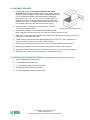
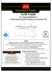
LABORATORY CERTIFICATION PROCEDURE I. INTRODUCTION ® ® Utilization of the ISTA Transit Tested Program has established the effectiveness of ISTA Preshipment Testing procedures as a deterrent to in-transit damage. The Transit Tested Program is based upon the concept that industry shall continue to progressively improve its performance packaging through preshipment testing so that an economic balance between overall packaging costs and physical distribution adequacy can be attained. The purpose of the Laboratory Certification from ISTA is to confirm that all such facilities are properly equipped and competently staffed to perform and evaluate preshipment testing of packaged-products in ® accordance with ISTA Preshipment Test Projects and Procedures, and that their results are within the same range as other ISTA Certified Laboratories. II. SCOPE The Laboratory Certification Procedure is designed to help standardize test results between package testing laboratories that wish to obtain and/or continue their membership as a Certified Laboratory of ISTA. The certification of any testing laboratory is dependent upon its possession of the necessary equipment, properly installed and maintained. Operating personnel must be capable of performing preshipment tests ® on packaged-products in accordance with ISTA Test Projects and Procedures, evaluating results and completing and submitting Certified Laboratory Test Report forms. Certification must be performed initially, upon application, and then biennially or as called for by the Technical Division Board by the member laboratory under responsible supervision. ® Data developed during the certification should be recorded on ISTA Equipment Verification forms as appended herein, and the originals forwarded to ISTA along with video as outlined in this document. An evaluation of the data, with appropriate comments, will be provided to the laboratory within thirty (30) days after receipt of the completed Equipment Verification forms and video. In the event that the evaluation discloses a need for the adjustment of laboratory equipment, appropriate suggestions regarding remedial action will be made by ISTA Staff. ISTA Laboratory Certification Procedures Updated: September 2013 ©2013 International Safe Transit Association. All rights Reserved. III. EQUIPMENT REQUIRED 1. A substantial wood box (corrugated containers will not be accepted) filled with sand or equivalent to a gross weight of 100 lb (45 kg). In order to maintain uniform data, it is required that this test box be a Nailed Wooden Box (end cleats INSIDE), measuring approximately 24" x 18" x 10", OD. It is recommended that it be retained and kept continuously available for periodic equipment calibration (See Figure 1). REQUIRED FOR CERTIFICATION OF ANY FIXED DISPLACEMENT VIBRATION TABLE AND INCLINE-IMPACT TESTER. 2. Carpenter's level. REQUIRED FOR CERTIFICATION OF ANY FIXED DISPLACEMENT VIBRATION TABLE. Figure 1: Style 2 Nailed Wooden test box 3. Calibrated tachometer or speed indicator for determining shaft RPM. REQUIRED FOR CERTIFICATION OF ANY FIXED DISPLACEMENT VIBRATION TABLE. 1 4. Metal shim /16 inch thick, approximately two (2) inches wide. REQUIRED FOR CERTIFICATION OF ANY FIXED DISPLACEMENT VIBRATION TABLE. 5. A solid surface to perform the Phase Relationship test (as described in A1.5, below). REQUIRED FOR CERTIFICATION OF ANY FIXED DISPLACEMENT VIBRATION TABLE. 6. Wooden pencil. REQUIRED FOR CERTIFICATION OF ANY FIXED DISPLACEMENT VIBRATION TABLE. 7. Blank paper. REQUIRED FOR CERTIFICATION OF ANY FIXED DISPLACEMENT VIBRATION TABLE. 8. Stop watch or watch with second hand. REQUIRED FOR CERTIFICATION OF COMPRESSION TESTER. 9. Measuring tape. REQUIRED FOR CERTIFICATION OF COMPRESSION TESTER. IV. ADDITIONAL EQUIPMENT REQUIRED (when applying for listed Projects or Procedures) 1 Top Load apparatus (Procedure 3A) 2 2 - Hazard Blocks (Procedure 3A) 3 2 – Consolidation Bags (Procedure 3A-small) 4 Dunnage materials (Procedure 3A-small) 5 Fork Truck Handling Course (Procedure 3B) ISTA Laboratory Certification Procedures Updated: September 2013 ©2013 International Safe Transit Association. All rights Reserved. V. VIDEO PROCEDURE This section of the ISTA Laboratory Certification procedure involves creating video(s) of the equipment and methods involved in certification, in lieu of an on-site inspection. This procedure is used for existing laboratories needing re-certification and by new laboratory members submitting their initial certification. This procedure is required on a biennial basis, regardless of changes to equipment since the last recertification. The video must include all parts of the video procedure (please note the checklist on the last page of this procedure - that will help you generate the video). Your video will be kept on file with ISTA, and therefore will become ISTA property. For this reason, please consider making a back up of your video to keep at your facility. If you need your video returned for any reason, please contact ISTA. MATERIALS REQUIRED See previous documentation for calibration equipment required. In addition, the following will be needed for the video: 1 A digital camera with video capability 2 Digital media (memory card; flash drive; CD-ROM; DVD; etc) 3 Blank sheets of paper and black pen for making titles. STEPS FOR VIDEO (a check list is included on the last page for your convenience) 1 Load digital media and prepare camera. A tripod, special lighting, batteries or electrical service or other accessories may be required according to the situation. 2 Prepare a title on a sheet of paper and videotape for approximately 10 seconds. Include the applicant laboratory name and address, Member ID number if applicable, and the date of taping. Additional titles may be used throughout the taping to identify equipment, but are not required. 3 Progress through the steps for each piece of equipment, below. Video each step in the Procedure that applies to your laboratory (required steps are labeled with an *). For each piece of equipment also show an overall view of the equipment, followed by the procedure as defined. When possible, zoom in to show details of the process. (Tip: having an assistant run the video equipment is easier than doing everything with one person.): A1. FIXED DISPLACEMENT VIBRATION (rotary or vertical linear motion) 1 Inspect the table surface. Rough, worn or painted surfaces should be replaced or cleaned. 2 Check the mounting bolts for tightness. 3 * Operate the machine through its entire frequency range to determine smoothness of operation. 4 * Show that the table surface is level: With the machine turned off, place a carpenter's level on the center of the table, parallel with the direction of motion. Manually rotate the carpenter's level slowly through one complete revolution. Should the bubble deviate from its original position, the table surface is not level and adjustment is required before certification will be approved. 5 * Verify phase relationship of the primary and secondary shafts (“Circle Test”; for rotary motion only): Clamp a wooden pencil at a corner of the table, parallel to the shafts, with the point extending beyond the edge. With the table operating at about 250 CPM, slowly bring a blank sheet of paper mounted on a stable surface (i.e., clip board attached to a hand truck) into steady contact with the pencil point for several revolutions. Repeat at each corner. If the resultant figures appear as 1 inch diameter circles at all four (4) corners then the shafts are operating in phase. Should any of 1 the resultant figures appear as an ellipse, or outside of the tolerance of +/- /16 inch, then the shafts are out-of-phase and adjustment is required before certification will be approved. Document the corner for each circle produced. The circles must be submitted to ISTA with certification materials. ISTA Laboratory Certification Procedures Updated: September 2013 ©2013 International Safe Transit Association. All rights Reserved. 6 * Sample Testing: Center the 100 lb wooden test box on the vibration table with one end panel against a fence (as applicable). Start the table at a low frequency and slowly increase the vibration frequency until the metal shim may be slipped along under the bottom edge of the box. You should be able to move the shim intermittently (at the top of each cycle) along one entire edge of the box in a direction parallel to the motion of the vibration tester. 7 Complete FIXED DISPLACEMENT VIBRATION Equipment Verification Form and return to ISTA along with circles requested in A1.5 above and applicable outside calibration documentation. A2. RANDOM VIBRATION 1 Inspect the table surface. Rough, worn or painted surfaces should be replaced or cleaned. 2 Check the mounting bolts for tightness. 3 * Operate the machine through its entire frequency range to determine smoothness of operation. 4 * Place the wooden test box on the unit and perform sample testing using the table below. Adjust any discrepancies in accordance with the manufacturer’s service manual. PSD breakpoints are available in the current ISTA Projects and Procedures listed, or contact ISTA for PSD breakpoints.: ISTA Project or Procedure Perform the following vibration profiles as shown in the applicable ISTA Procedure. (Submit control plots with Equipment Verification Forms and video): 1G 1H 2A 2B 2C Random vibration spectrum, overall Grms: 1.15 Theoretical stroke: 0.884 in (22.45 mm) peak-to-peak. 2C 3B 3E 3H 2C 3H Steel Spring Truck spectrum, overall Grms Theoretical stroke: 1.777 in (45.13 mm) peak-to-peak. 3A Over-the-Road Trailer spectrum, overall Grms: 0.53 Theoretical stroke: 1.855 in (47.12 mm) peak-to-peak. 3A Pick-up and Delivery Vehicle spectrum, overall Grms: 0.46 Theoretical stroke: 2.312 in (58.72 mm) peak-to-peak. 3H Rail spectrum, overall Grms: 0.13 Theoretical stroke: 0.837 in (21.26 mm) peak-to-peak Random vibration spectrum, overall Grms: 0.51 Theoretical stroke: 0.950 in (24.13 mm) peak-to-peak. Air ride truck spectrum, overall Grms: 0.28 Theoretical stroke 2.14 in (54 mm) peak-to-peak 3A (optional) 5 Vibration under low pressure spectrum, overall Grms: 1.05 Theoretical stroke: 0.296 in (7.52 mm) peak-to-peak. 6SAMSCLUB Random vibration spectrum, overall Grms: 0.464 Theoretical stroke: 1.556 in (39.5 mm) peak-to-peak 6SAMSCLUB Random vibration spectrum, overall Grms: 0.552 Theoretical stroke: 1.649 in (41.9 mm) peak-to-peak Complete RANDOM VIBRATION Form and return to ISTA along with applicable control plots and applicable outside calibration documentation. ISTA Laboratory Certification Procedures Updated: September 2013 ©2013 International Safe Transit Association. All rights Reserved. B1. INCLINE IMPACT TESTER 1 Inspect the dolly surface. Rough, worn or painted surfaces should be replaced or cleaned. 2 Check the mounting bolts for tightness. 3 * Perform the verification test from the Equipment Verification Form: Perform 5 empty dolly impacts from the top of the incline to assure free running of the wheels and smoothness of operation. Perform 5 loaded runs with 100 pound test box on dolly. 4 * Record velocimeter readings and calculate inches per second on Page 2 of Equipment Verification Form. 5 Complete both pages of the INCLINE IMPACT TESTER Form and return to ISTA along with applicable outside calibration documentation. B2. HORIZONTAL SLED IMPACT TESTER 1 Inspect impact surface. Rough, worn or painted surfaces should be replaced or cleaned. 2 Check mounting bolts for tightness and rails for alignment and smoothness of surface. 3 * Make five impacts to assure free running and smoothness of operation. 4 Complete HORIZONTAL IMPACT SLED Form and return to ISTA along with applicable outside calibration documentation. C1. FREE FALL DROP TESTER 1 Inspect the surface of the drop table leaves, swing arm platform or other surface on which the packaged-product being tested may rest. Rough, worn or painted surfaces should be replaced or cleaned. 2 Check the surface upon which packaged-products are dropped. Rough, worn or warped areas should be replaced. 3 * Determine that dropping surface is an unyielding (solid) base by tapping on it with a hammer or similar device. 4 * Operate release mechanism to determine that packaged-products will fall without restraint. 5 * Sample Testing: Determine that release mechanism allows the packaged-product to strike base properly (i.e., that base is horizontal and that packages dropped impact the base with no deviation from the horizontal). This is accomplished by doing sample drops on a corner, edge, side and end, using a 5-25 lb actual or simulated packaged-product. 6 Complete FREE FALL DROP TESTER Form and return to ISTA along with applicable outside calibration documentation. C2. SHOCK TEST SYSTEM 1 Inspect any surface on which the packaged-product being tested may rest. Rough, worn or painted surfaces should be replaced or cleaned. 2 Check the mounting bolts for tightness. Determine that unit is anchored in accordance with manufacturer's recommendations to an unyielding (solid) base. 3 * Operate release mechanism to determine if packaged-product receives indicated shock accurately. 4 * Sample Testing: Determine that release mechanism allows the packaged-product to be impacted solidly. This is accomplished by doing a sample test on a corner, edge, side and end, using a 5-25 lb actual or simulated packaged-product. 5 Complete SHOCK TEST SYSTEM Form and return to ISTA along with applicable outside ISTA Laboratory Certification Procedures Updated: September 2013 ©2013 International Safe Transit Association. All rights Reserved. calibration documentation. D. COMPRESSION TESTER 1 Inspect all surfaces to be certain that they are smooth and horizontal when at rest. 2 * Sample Testing: Operate unit to assure that compression rate is constant and within limits (use a measuring tape and run the machine, showing that the platen moves at the required rate). 3 * Sample Testing: Load and operate unit to show that platens do not deflect at a maximum rated load (do not use maximum force if it will damage the machine). 4 Complete COMPRESSION TESTER Form and return to ISTA along with applicable outside calibration documentation. E. ENVIRONMENTAL CONDITION CHAMBER 1 Inspect unit to see that seals are tight and not worn. 2 * Operate unit and verify that temperature can be maintained within +/- 4 degrees Celsius (show instrumentation). 3 * Operate unit to verify that relative humidity can be maintained within +/- 5% (show instrumentation). 4 Complete ENVIRONMENTAL CONDITIONING CHAMBER Form and return to ISTA along with charts or graphs showing temperature and humidity function and applicable outside calibration documentation. Continued next page… ISTA Laboratory Certification Procedures Updated: September 2013 ©2013 International Safe Transit Association. All rights Reserved. COMPLETING THE EQUIPMENT VERIFICATION FORMS Required for re-certification approval are Equipment Verification Forms. These forms are vital to documenting your laboratory’s capabilities and capacities. A form must be filled out completely for each piece of equipment used for ISTA testing. Leave blank those forms that represent equipment you don’t have. If your equipment does not utilize listed instrumentation, leave those fields blank as well. LABELING YOUR VIDEO(S) Please label your files and electronic media with the Company Name and ISTA Member ID (if applicable). SUBMITTING YOUR MATERIALS All lab certification materials should be in a digital format. You can submit them electronically or by post/courier. Materials can be submitted by email, online or on electronic media including memory card, flash drive, CD or DVD. The video(s) can be submitted in one of the following file types: .mpg, .avi, .mov, .wmv, .mod, .mp4, .rm, .rar, .zip, If you have a different file type please contact ISTA. Equipment Forms can be submitted via email by clicking the button SUBMIT BY EMAIL at the top of the Fixed Displacement Vibration form after you’ve completed filling out the forms. You may also submit them with your video(s) by way of electronic media. Additional documents that must be submitted with your lab certification, and which can also be sent electronically, include: Calibration certificates to a traceable source (calibration is required on an annual basis) Control plots if certifying to Procedures 3A or 3E, and/or to Project 3B and 6-SAMSCLUB Circles for rotary motion fixed displacement vibration Electronic Submission: Use ISTA’s ‘You Send It’ account: http://dropbox.yousendit.com/ISTA Email to [email protected] Use your company’s FTP (email the link and directions to [email protected]) Use the ISTA upload feature: http://www.ista.org/upload.php NOTE: If you use the ISTA upload feature, please send an email to [email protected] once your file(s) have been uploaded. This web feature can accept files totaling up to 100MB; you may upload more than one file but the total file size can not exceed 100MB. Post or Courier Submission: Send all documents (equipment forms, calibration documents, photos, applicable control plots, circles, etc) and video(s) to: ISTA Headquarters 1400 Abbot Road, Suite 160 East Lansing, Michigan 48823-1900 USA ISTA Laboratory Certification Procedures Updated: September 2013 ©2013 International Safe Transit Association. All rights Reserved. You may use the following Check List to be sure that all pertinent information is included on your videotape. This form is for your use and need not be returned with the forms and video. CATEGORY FUNCTION TO TAPE A1/A2: Vibration Overall View DONE Frequency run-through Levelness of table Phase Relationship (circles - Rotary Motion only) Sample Testing: Use of Test Box and metal shim B1/B2: Incline/Horizontal Impact Overall view Verification test (fill out back side of equipment form): impacts, free running and loaded Controls view C1/C2: Drop/Shock Overall view Release mechanism shown Sample Testing: drops on end, side, corner, edge D: Compression Overall view Sample Testing: Consistent compression rate Sample Testing: Platen deflection Controls view E: Environmental Chamber Overall view Controls view F: Additional views Optional Show outside of lab, any non-lab office space, etc. G. Additional Equipment (submit photos or drawings) 3B fork handling course (drawing or photo) 3A Top load apparatus (photo) 3A Hazard blocks (photo) 3A Small dunnage/bags (photo) Submission Materials (as applicable) Equipment Verification Forms Video(s) Vibration Control Plots Atmospheric Chamber graphs Vibration Circles Calibration Documentation ISTA Laboratory Certification Procedures Updated: September 2013 ©2013 International Safe Transit Association. All rights Reserved.