1
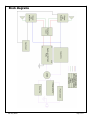
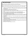
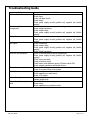
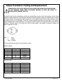
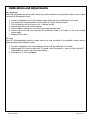
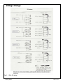
Classé Audio Inc.
Date:
August 27, 2007
Model Number:
DR-9
Subject:
Service manual
Classé Audio, Inc. 5070 François Cusson Lachine, Québec Canada H8T1B3, www.classeaudio.com
PRO-SVR_LEGACY
Page 1 of 11
Table of Contents
Introduction 3
Important Notes on Servicing 3
Ordering Replacement Parts 3
Block Diagrams 4
Start up Procedure 5
Protection Modes and Indicators 6
Troubleshooting Guide 7
Output Transistors Testing and Replacement 8
Calibrations and Adjustments 9
Fuses 10
Voltage Change 10
Schematics 12
The contents of this document as well as the files associated with it contain confidential information that is proprietary to Classé Audio
Incorporated and are intended solely for the purpose of servicing product. No part of its contents may be used, copied, disclosed, or conveyed to
any party in any manner whatsoever without prior written permission from Classé Audio Incorporated.
PRO-SVR_LEGACY
Page 2 of 11
Introduction
Please read this manual carefully before commencing servicing!
Only qualified and authorized personnel should attempt to service this product.
The lightning flash with arrowhead symbol, within an equilateral triangle, is intended
to alert the user to the presence of uninsulated dangerous voltage within the
product’s enclosure that may be of sufficient magnitude to constitute a risk of electric
shock to persons.
The exclamation point within an equilateral triangle is intended to alert the user to
the presence of important operating and maintenance (servicing) instructions.
Classé has a global product support network. For product assistance or to order replacement parts please
contact your nearest service center always quoting the unit serial number.
North America
Phone: (978) 664-2870 E-mail: [email protected]
Europe
Phone: 44 (0) 1903 221 700 E-mail: [email protected]
Asia
Phone: (852) 2790 8903 E-mail: [email protected]
Rest of the World
Phone: (514) 636-6384 E-mail: [email protected]
Important Notes on Servicing
1. ALWAYS observe ESD precautions when handling electronic modules or PCBAs.
2. NEVER exchange boards with a different revision number, unless authorized by Classé.
3. ALWAYS use Classé original replacement parts. The use of generic parts may void the warranty of
the unit.
Ordering Replacement Parts
There may be a delay in processing incomplete requests. Please be sure to include all required information.
Remember to quote the serial number of the unit on all replacement part orders and the Classé order number
when returning defective parts for credit.
PRO-SVR_LEGACY
Page 3 of 11
Block diagrams
PRO-SVR_LEGACY
Page 4 of 11
Start Up Procedure
When receiving a unit, an assiduous visual inspection must be performed. Do not connect the unit without
analysing the symptoms reported by the customer and the results of the inspection.
Using the troubleshooting guide, find the problem and proceed to the repair. Once this step is done, follow
these steps, known as the start-up procedure, to ensure that everything in the unit is in working condition.
1. Proceed with a post repair visual inspection. Take the time to check if every wire is reconnected
properly, every screw is bolted on, no soldering and/or metal residues lying in the unit, every fuse has
been replaced, etc.
2. Connect the unit to a variable transformer, setted to 0Vac.
3. Turn the bias trimpot (R16) counter clockwise until a click is heard.
4. Slowly raise the voltage to 10Vac, and check positive and negative rails and pre-driver supply. Check
fuses.
5. If one or more supply are not within specifications, return to the troubleshooting guide.
6. Slowly raise voltage until you hear relays click, this point is around 55Vac. Recheck every supply.
7. If one or more supply are not within specifications, return to the troubleshooting guide.
8. Raise voltage to 120Vac. Recheck every supply.
9. Report to Calibration and adjusments to adjust bias and DC offset. Note that bias can be adjusted to
14mV, and the following tests can be performed before the unit is send to the burn-in bench for a 24
hours warm-up.
10. Connect the unit to a load, and to a source using balanced inputs and single ended inputs,
independently.
11. Perform a test with a 200Hz, a 2kHz and a 20kHz tone, both sinus wave and square wave. Check the
output with a oscilloscope, on 4 ohms and 8 ohms loads. Take special cares about oscillation and phase
correlation between channels.
12. Connect the unit to a small speaker, and short the input. Check for any noise. Perform this step with
single ended inputs and balanced inputs, independently.
13. Put the unit on a burn-in bench, and let it sit for 24 hours, then readjust bias. Let the unit on the burnin bench for another 72 hours.
14. Redo steps 10 to 13 before shipping to the customer.
PRO-SVR_LEGACY
Page 5 of 11
Protection Modes and Indicators
The protection circuit on the DR-9 is triggered by a high DC offset condition. This is the only protection
available on this unit. Therefore, extra precautions should be taken to make sure the unit is OFF before
manipulating the connections.
When a high DC offset is present at the output, the protection circuit opens both output relays, even if the
condition is only present on one channel. If the relays are intermittently clicking, DC offset should be
monitored for a long period of time, to make sure DC offset caused that condition, and not the protection
circuit itself that is running out of specifications.
PRO-SVR_LEGACY
Page 6 of 11
Troubleshooting Guide
Symptom
Unit won’t turn on
Smoked and/or burned
components
Blown fuses
No output
Unit turn into protection
Excessive buzz and/or hum
Oscillation
Intermittent signal
Intermittent / fast output relay
click
PRO-SVR_LEGACY
Possible cause
Check connections;
Check fuses;
Check soft-start circuit;
Check relays;
Check power supply circuits (positive rail, negative rail,
supply).
Check for short between components and ground;
Check output transistors;
Check output relays;
Check power supply circuits (positive rail, negative rail,
supply).
Check for short between fuse and ground;
Check power supply circuits (positive rail, negative rail,
supply).
Check connexions;
Check output relays;
Check power supply circuits (positive rail, negative rail,
supply);
Check output transistors.
Check for smoked and/or burned components;
Check power supply circuits (positive rail, negative rail,
supply);
Check source and load;
Check protection circuit;
Check sensor wires between sensor PCB and control PCB;
Check outputs transistors and Mosfet drivers.
Check electrical lines;
Check for a ground loop in the system.
Check source;
Check capacitors on main board;
Check 4.7ƻ resistor.
Check connections;
Replace shield wires.
Check DC offset before relays;
Check relays;
Check capacitors on protection circuit.
Mosfet
Mosfet
Mosfet
Mosfet
Mosfet
Page 7 of 11
Output Transistors Testing and Replacement
PLEASE NOTE THAT THESE TESTS ARE ONLY EFFECTIVE ON BIPOLAR TRANSISTORS.
DO NOT PERFORM THESE TESTS ON MOSFET DEVICES, AS THEY ARE LIKELY TO
BECOME SHORT DURING THE TEST.
You should check all pin combinaisons, as there is a chance that only one side of the transistor is short. When
replacing outputs transistors, the technician should first disconnect both outputs and main board to check if
the blown outputs were caused by a faulty component on the amplifier’s base. Blown output transistors should
be replaced by kits, not individually. These kits contains matched transistors for both rails of one channel.
When replacing blown output transistors, you must also replace positive and negative Mosfet drivers and bias
transistor. Carefully inspect 4.7ƻ resistor and 10ƻ soft start resistor, and replace if necessary. Replace any
burnt component or board.
Pins : 1
2
Case
Base
Emitter
Collector
You should have these results, if the transistor is good.
MJ15024 (NPN)
Positive lead
B
B
C
C
E
E
Negative lead
C
E
B
E
B
C
Result
Conductive
Conductive
Infinite
Infinite
Infinite
Infinite
Negative lead
C
E
B
E
B
C
Result
Infinite
Infinite
Conductive
Infinite
Conductive
Infinite
MJ15025 (PNP)
Positive lead
B
B
C
C
E
E
PRO-SVR_LEGACY
Page 8 of 11
Calibrations and Adjustments
Bias adjustment:
Note: Bias adjustment should be made without any load connected to the amplifier’s output, and no signal
connected to the amplifier’s input.
1.
2.
3.
4.
5.
6.
Connect a multimeter to one of the emitter resistor leads and set the multimeter to mV scale.
Turn trimpot R16 counterclockwise until it reaches 0ƻ. A click should be heard.
Turn on amplifier, and let it warm up for 15 minutes on idle.
Adjust trimpot R16 to get a 14mV reading.
Let the amplifier warm up for a 24 hours period with signal and load.
Remove signal and load, and reconnect the multimeter, setted to mV scale, to one of the emitter
resistor leads.
7. Readjust R16 to 18mV
DC offset:
Note: DC offset adjustment should be made without any load connected to the amplifier’s output, and no
signal connected to the amplifier’s input.
1. Connect a multimeter to the output binding posts and set the multimeter to mV scale.
2. Adjust trimpot R5 in order to reach 0mV. It is easier to turn the trimpot ½ turn at a time, and let DC
offset stabilize in order to get an accurate reading.
3. A tolerance of ± 1mV is acceptable.
PRO-SVR_LEGACY
Page 9 of 11
Fuses
EXTRA PRECAUTIONS SHOULD BE TAKEN WHEN REPAIRING, MODIFYING, OR
TROUBLESHOOTING IN THE POWER SUPPLY AREA. UNIT MUST BE DISCONNECT
FROM MAIN SOURCE AND CAPACITORS MUST BE DISCHARGED USING A 100W
INCANDESCENT BULB.
WHEN REPLACING FUSES, PLEASE MAKE SURE THAT THE FUSE HOLDERS ARE
HOLDING THE FUSES VERY TIGHTLY. A LOOSE FUSE HOLDER CAN TRANSLATE INTO
DISTORTION ON TOP OF THE SIGNAL.
Main fuses:
For 100 – 120v units: 8A slo-blo, Classe part number MDL-8A
For 220 – 240v units: 6A slo-blo, Classe part number MDL-6A
The main fuse is located at the back of the unit, on the rear panel.
Voltage Change
EXTRA PRECAUTIONS SHOULD BE TAKEN WHEN REPAIRING, MODIFYING, OR
TROUBLESHOOTING IN THE POWER SUPPLY AREA. UNIT MUST BE DISCONNECT
FROM MAIN SOURCE AND CAPACITORS MUST BE DISCHARGED USING A 100W
INCANDESCENT BULB.
Using a ohmmeter, locate and label each of the four transformer windings. Rewire the terminal block,
according to the schematic in fig. 1.
Replace varistor with correct value.
PRO-SVR_LEGACY
Page 10 of 11
Voltage Change
Fig. 1 – 120v AC wiring
PRO-SVR_LEGACY
Page 11 of 11