1
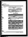
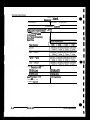
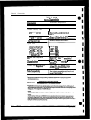
User3 Reference
TEK
Supplement
-,_
Part No. 070-5921-00
Product Group 47
llA34
Four Channel
Amplifier
Serial
Number-
Please check for CHANGE INFORMATION in the rear of this manual.
-
First Printing FEE 1987
RevisedOCTi987
-
- .
<
. .
-m.-..
.--..e
.
TEK .INTER-OFFICE COMlvllJNlCATlON
..
TO
FWW
M3KC.T
Sohn
94-540
Martin
3:.' t
Juno 25, 1991
Frank Gray, SO-PAT
GIDEP permit
request
In response to the request to grant permission to the
Industry Exchange Pro ram (GPDEP) to reproduce
Tektronix
operator,
service and P nstruction
manuals,
Tektronix,
Inc. hereby grant6 such permission for distribution
of such documents to any GTDEP user that is a full
participant
in the Metrology
Data Interchange Data Base of GIDEP provided
that
all
copies
of the original
work include the entire
copyright
notice and ownership statement exactly a-& it appears
in the original,
together with the Legend "Reproduded with
Government
pemieeion,a
This permission has been approved by the Intellectual
Committee
of Tektronix
and
a copy
of this
memo
aeon% 1[ded to GIDEP to provide'the requested
permission.
g:&dy
Group Pat&t
Coun&al
may
INSTRUMENT SERIAL NUMBERS
Each instrument has a serial number on a panel insert, tag, or stamped on the chassis. The
firat number or
letter designates the country of manufacture. The last five digits of the serial number are assigned sequentially and are unique to each instrument. Those manufactured in the United States have six unique digits.
The country of manufacture is identified as follows:
B000000
100000
200000
3aoooo
700000
Tektronix, Inc.. Beaverton. Oregon, USA
Tektronix Guernsey. Ltd., Channel Islands
Tektronix United Kingdom, Ltd., London
Sony~ektmnix, Japan
Tektronix Holland, NV, Heerenveen, The Netherlands
CopyrightQ Tektronix, Inc.. 1987. All tights resewed. Tektronix products are covered by US. and foreign
patents, issued and pending. TEKTRONIX, INC. SCOPEMOBILE and
are registered trademarks.
Printed in U.S.A.
llA34 Features and Functions
Feattues
Dual trace
Up to 300 MHz bandwidth (in 114M)
Calibrated sensitivities from 1 mV to 10 V/division
5lX2 or 1 MR input impedance
High-resolution, calibrated DC offset
division/inoement, fine)
.
FUllCtiOllS
(0.25 division/increment, coarse; 0.025
Fast ovwdrive recovery
Signals applied to the CH I, CH 2, CH 3 and M 4 input co~ectors can be
displayed or removed from the display by pressing the display on/off buttons
adjacent to the input connectors.
All other llA?A functions are conkoUed through the host mainframe. Such
ontrolled func!ion5 are:
9 Sensitivity, Coarse and Fine, over a range of 1 mV to 10 V/division.
l
verticaloffset
l
Coupling: AC, DC, or Off.
l
Impedance (input termination): 5On or 1 MC&
l
Bandwidth Limit: 100 MHz or 20 MHz
l
Display Polarity: normal or inverted
l
Trigger Polarity: normal or inverted.
l
l
Combination of Display Channels: see Operating Information section of
mainframe User’s Reference manual.
Combination
of
InfontWion
Trigger Channels: same as Display Channels; zee Operating
section of mainframe User’s Reference manual.
Contents
Part l-General Information
Technical Manuals .......................................................................................................
l-l
Contents o f this Supplement .................................................................................
1-l
1 IA34 Service Manual ............................................................................................
l-2
Plug-in to Mainframe Compatibility ........................................................................
l-2
hitiel tmp&ion .......................................................................
*. ................................. l-2
Operating Temperature ..............................................................................................
1-3
Installing and Removing t h e llA34 ....................................... +.................................. l-3
Irlstrument options .....................................................................................................
14
Packaging for Shipment ..............................................................................................
l-5
Part 2-Operatig the llA34 in 11301 and 11302 Mainframes
Display On/off .... _*. ...................................................................................................
2-l
S&ding Coupling. HF Limit, and Impedance .......................................................
2-l
2-2
Other Functions .............................................. ..............................................................
2-2
Position and Offset ......................................................................................................
H F Limit ........................................................................................................................
2-3
D C C i i t Loading ..................................................................
. .................................. 2-3
Adding Waveforms ..................................................................
. .................................. 24
overdrive Recovery ....................................................................................................
2-4
2-7
5OfI Overload ................................................. *.............................................................
Active Probe. ...............................................................................................................
2-7
Probe II3 ........................................................................................................................
2-7
FronH’anel Error Messages .......................................................................................
2-8
GPIB and -232-C Co mmands and Syntax ..........................................................
..2- 9
Part 3-0perating the llA34 in 11401 and 11402 Maiaframes
Display O n / O f f . ..._ .............. . ......................................................................................
Other Functions ............................................................................................................
Vertical Offset ...............................................................................................................
BW Limit .............. *.....-....-^
...... . . . . . . . . .........................
..- ....................................
.
D C Circuit Loading ,._ .......................................... *. ....................................................
Ad&g and Subtracting Wavefoti .................................................. +. ...................
overdrive Recovery ................
. . . . . . . . . . . . . . . . . . . .. . . . . ... . ..........................................
5On Overload .......................................................................................
..*. ....................
Active Probes ................................................................................................................
.3-l
3-l
3-2
3-2
3-2
.3-4
3+5
3-a
3-8
Robe rD ...................... _*. .._ ............ . ... . . . . ”. ............................................................
3-8
Front-Panel !&or Messages .................................................................
. .................. .3-10
GlTB and lGGJ32-C Commands and Syntax.. ........................................................
3-11
Part
P-Specification
Performance Conditions .............................................................................................
Electrical Characteristic3 ............. ..........................................................................
Environmental Qlsracteristics ..............................................................................
Physical Characteristics..........................................................................................
Recommended Probes .................................... ..fl........................................................
11 AZ4 User’s Reference Supplement
RM JUL 1987
llA34
4-1
.4-l
4-7
4-a
4-8
i
L
Appendix A-Glossary . . . . . . . . . . . . . . . . . . . . . . . . . . . . . . . . . . . . . . . A-l
Appendix B-hstrument Documentation . . . . . . . . . . . . . . . . . . . . . . . . . . . B-1
Illustrations
l - l Installing a plug-in unit in a mainframe oscilloxope ,a..< tt.tt.t.t..t.t..tttl,..,.,,,.,
I-4
2-I Location of A C coupling capacitors in plug-in amplifiers . . . . . . 2-3
2 - 2 Overdrive recovery using long (top) and short (bottom) cables
terminated in SOR. Traces ore offset two divisions and the
photograph is a double exposure .,,....,...,,.......................................................
2-5
2 - 3 Overdrive recovery using long (top) and short Coottorn) cables
uriterminated. Traces are offset ,hvo divisions and the photograph
is a double exposure . . . . . . . . . . . . . . . . . . . . . . . . . . . . . . . . . . . . . . . . . . . . . . . . . . . . . . . . . . . . . . . . . . . . . .
..~.................
2-6
3-1 Location of AC coupling capacitors in plug-in amplifiers . . . . . . . . . . . . . 3-3
3 - 2 Overdrive recovery using short (top) and long (bottom) cables
terminated in 50~2. Traces are offset two divisions and the
illustration is a composite of t w o waveforms . . . . . . . . . . . . . . . . . . . . . . . . . . . . . . . . . . . . . . . . . . . . . . .
3-6
3 - 3 Overdrive recovery using short (top) and long (bottom) cables
unterminated. Traces are offset two divisions and the illustration
is a composite of two waveforms .t....t.t....tt........,..,,.,.,,.~........,.,,......
+ t...tt.l..t.... 3-7
34 Sequence of decisions used to select a new waveform in response
t o probe ID button . . . . . . . . . . . . . . . . . . . . . . . . . . . . . . . . . . . . . . . . 3 - 9
4 - 1 Dimensions of llA34 . . . . . . . . . . . . . . . . . . . . . . . . . . . . . . . . . . . + . . . . . . . . . . . . . . . . . . . . . . . . . . . . . . . . . . . . . . . . . . . . . . . . . . . . . 4-9
Tables
2-l
3-l
4-l
4-2
4-3
ii
llA34
Functions A n d Where They Are Described ..................................................
Functions A n d Where They Are Described ..................................................
Rlectrical Characteristics ..................................................................................
Environmental Characteristics .........................................................................
Physical Characteristics.....................................................................................
REV OCT 1987
.2-2
.3-l
.4-l
4-7
4-8
llA34 Lker’s Reference Supplement
I.
c
I
e
-I
Illustrations
l-l Installing a plug-in unit in a mainframe osdllosope . . . . . . . . . . . . . . . . .*._ .+.... t . . . . 14
2-1 tocation of A C coupling capacitors in plug-in amplifiers . . . . . . . . . . . . . . . . . . . . . . . . . . . 2-3
2 - 2 Overdrive recovery wing long (top) and short (bottom) cables
terminated in Mfi Traces are offset two divisions and the
phomFaph is a double exposure ..__.._.._...........................................l..............
2-5
2 - 3 Overdrive recovery using long (top) and short (bottom) cables
unterminated. Traces are offset two divisions and the photograph
is a double exposure . . . ..._...._ _ ._.. _ . . . . . ._ . . ..._._.._.._.._._................................~.............
26
3-3
3-l Location of AC coupling capacitors in plug-in amplifieft ._.........................
3 - 2 Overdrive recovery using short (top) and long (bottom) cables
terminated in 5OR. Traces are offset two divisions and the
illustration is a composite of t w o waveforms . . . . . . . . . . . . . _ . . . . . . . . . . . . . . . . . . . . . . . . . . . . . . . . .
36
3 - 3 Overdrive recovery using short (top) and long (bottom) cables
unterminated. Traces are offset two divisions and the illustration
is a composite of t w o waveforms . . . . . . . . . . . . . . . ..._..................................................
3-7
34 Sequence of decisions used m select a new waveform in responw
m probe ID button..... . . . . . . . . _ .._...._.,....._..................
_ . . . . . . . . . . . . . . . . . I . . . . . . . . . . . . . . . . . . . . . . . . . . .3 - 9
I ,....... 4-9
4-1 Dimensions of llA34 . .._...._._. _ _............_.._._...........................................,....
5-14
5-1 Input disconnect time and threshold waveform ,............._.._.......................
Tables
2-1
3-1
4-l
4-2
4-3
5-l
Functions A n d Where They Are Dezrikd ................... . ............................... 2 - 2
Functions And Where They Are Described ................................................... 3-l
4-l
Electrical Chafacteristics ...................................................................................
Environmental Characterisrics ......................................... ................................ 4 - 7
physical characteristics ..................................................................................
...4-a
Test Equipment Required .................................................................................
5-1
11X34 User’s Reference Supplement
nA34 i i i
Part 1
General Information
Technical Manuals
‘his Supplement to the mainframe
User’s Reference manuals and the Incoming
Inspection Procedure manual are standard accessories to the IlAX For a list of
dated manuals, see Appendix B.
Contents of this Supplement
This Supplement contains the following five park
Part I-GENERAL INFORhJATION, de&W mainframe to plug-in unit
compatibility, explains how to install and remove the llA34 from a
mainframe,outinesany options available for the llA34, and gives details
about packaging for shipment.
Most llA34 functions, and their use, are d&bed in the Operating Information
section of the mainframe User’s Reference manuals. These functions are common
to all amplifier plug-in units. Examples of common functions are offset,
sensitivity, input impedance (where selectable), coupling. and bandwidth
limit. Only functionsuniquetothe11A34-11301/11302or11A34-11401/11402
combinations are explained in the following parts.
Part Z-OPERATING THE llA34 IN 11301 AND 113X MAINFRAMES,
explains how to operate those: llA34 functions not covered in the 11302 User’s
Reference manual.
Part3-OPERATINGTHEllA34IN11401AND114MMAINFRAMES,
explainshow tooperatethose llA34func!ionsnot covered in the 11401 and
11402 User’s Reference manual.
Part 4-SPECIFlCATION, gives detailed specifications of all llA%
mainframe oscilloscope combinations.
11 A34 User’s Reference Supplement
REVccri987
llA34
l-l
1 lA34 Service Manual
The 1 lA34 Semi% manual isfor use ty qua&d m&e personnel
only. Toamidpmsonalinjuy, do notperform myserkceother
‘than that contnined in the Operators manual unless you are
qulifialto aoso.~tOthe~torsSafety~ummarynlld
&mice Safely Summa ybefDre performing anyservtw.
The 1 1M4 service manual
contains the f0110wing information:
Se&on 14ENER4L INFORMATION.
Section 2-THEORY OF OPERATION.
Section S-MAINTENANCE AND lX4GNOSTIcS.
Section 4-PERFORMANCE
SacdonS-INSTR-
VF+XXATION
OM’IONS.
Section &REPLACEABLE EJBZTRKAL
Section 7-SCHEMATIC
ILLUSTRATIONS.
AND ADJLEIMENT.
PARTS.
DIAGRAMS AND CIRCUIT WARD
!Seciion &REPLACEABLE MECHANICAL PARTS.
Plug-in to Mainframe Compatibility
The11A34isd~ignedforuseinthe11301,11302,11401,11402,andfuturell~
series plug-in mainframes. 1 lA+ bandwidth varies depending on the host
mainframe. Details about bandwidth are included in Part& Specification, of
this Supplement, and in the Tektronix Corporate Catalog. Refer to the
Tekbonix Corporate C&lag for complete compatibility information.
Initial Inspection
This instrument was inspected mechanically and elecwically More shipment.
It should be free of mars or scratches and should meet all elech-ical
specifications. First, inspect the 1lAX for physcial damage incurred in transit.
Secondly, to verify that the instrument is functioning properly, perform the
Incoming Inspeclion Procedure, shipped with the instrument. This brief
procedure verifies nrose instrument functions and checks the internaY autccalibration references. If you find inwwnent damage OF deficiency, contact your
local Tektronix Field office or representative.
I-2
llA34
REVOCT 1987
Part 143neral Information
Operating Temperature
ThellA34eanbeoperatedwheretheambientairtem~hrreisbetweenO”
and twc and can be stored in ambient temperature3 from 4P to t7sT. After
storage at temperatures outside the operating limits, Aow the chassis to reach
opratixtg temperature hits More applying power.
Installing and Removing the llA34
To awid instrument dmmgc set the mainframe ON/STANDBY
switch to STANDBY b&einstaUingorremving
the llA.34.
when the STANDBY
posiiiot~ is selected, themitch bps been intentaay d*rbkd.
rffhEgw.m indbrator fight remzim ON,
To remove orreimfdl plug-in unii$, use the
mainframe
PRlNC.lPALPOWRSWlTCH~rar~~ toshutOfFthe
pwr. Thk wdl pwoent damage to dth.9 the plug-in or the
IMit4frmnc.
To onceap’n enable the ON/STANDBYm’tch,
imAt to qua&d Seroice~Rml.
r&the
When in5taUed inany 11401/11402 plug-in comparbnent, or in the i1301/11302
left or center plug-in compartment, the 1 IA34 will provide a conventional
display.
When in5iaUed in thecenter or right phig-incompartment of the 11301/11302,
the 11.43-i will ako provide theX (horizontal) part of an X-Y display, or
provide a tigger signal for the mainhame time base.
Toinskdl thellA34inanytlWOseriesosdlloscopemainframe,set
the
mainframe ON/STANDBY stitch to STANDBY. Align the grww in the tap
and bottom of the llA34 with the guides in the mainframe plug-in
compartment, then b3-t the 111334 into themainframe until its front panel is
f&h with the front panel of the mainframe.
To remve the llA?A from a meimbme, Set the maikame ON-=ANDBY
switch to STANDBY. Then pull the release latch be fig. 1-I) to disengage
the unit from the IT Cnfmme, and pull the 11.434 stmight out of the plugin
compknent
IL434 U&s p.eference Supplement
Installing and Removing the llA3
Figure 1-I. Installing a plug-h unit in a mainframe oscilloscope.
Instrument Options
Option 23 indude four P6134 probe%
Packaging for Shipment
lf this inshwment is to be shipped by commer&l transportation, we recommend
that it be packaged in the original manner. The ori@ carton and packaging
material can be saved and reused for this pu’p~se+
NOTE
Puckiagennd ship plug-in units rind muinfrmncs sepnmtely.
If the llA34 is to be shippad to a Tekaonix Service Center for service or repair,
al-hch a tag to the insirumen~ On the tag. include the following information:
Name and address of the instrument owner;
l
. Name of a person at your firm who can ba contacted about the instrument;
l
Complete instntrnent type and serial nun-&r, and
l
A da=cription of the service quired.
If theori@nal package isnot available or is not fit for use, package the IL434
as follows:
1.
Obtain a corrugated cardboard carton with inside dimensions at least six
inches greater than the iwtmnent dimensions. Use a carton with a test
strength of at least 2M) pounds.
2.
Fully wrap the ltA34 with snti-s!atic sheeting, or its equivalent, to
protect the finish.
3.
Cushion the llA24 on all sides by tightly pa&ng dunnage or urethane
foam between the carton and the instrument. Allow thrfx inches of
packing on each side.
4.
Seal the carton with shipping taupe or with industrial staples.
5.
Mark the address of the Tektmnix service Center and your rehw address
on the carton in one or more prominent places.
llAZ4 U&s Reference Supplement
lf301 ad 11302 Mainframes
Display On/Off
The llA34 has only four front-panel contmols-the display on/off buttons.
Pressing a display on/off button will cause its chamwL and signal, to be
displayed or removed from the display (the function “toggles”). When a
channel is displayed, its label ((311, Cl-I 2, CK 3, or CH 4) will be lighted.
Selecting Coupling, HF Limit, and Impedance
To select the desired setting for Coupling, FIF Limit, 0~ Impedance, proceed as
follows:
la. If no trace is displayed, pre55 any plug-in display on/off button to create a
h-ace.
lb. If several traces are diiplayed, select a channel by touching the desired
trace description at the top of the at.
2.
Press any VERTICAL button--OFFSET, SEE, or PG. This button-pre%
will cause the Control Menu to be displayed.
3.
Touch the desired function’s label. Successive touches will change its
state.
llA34 User’s ReferenceSupplement
nA34
2-1
Other Functions
Ohs ~~?4functi011~amcontrolledwithin
the 11301 or11302mainframe,and
their operation is described in detail in Section 2, Operating Information, of the
11301 andl1302User’sReferencemanual. Table2-1 showswhereto hd
informationabout operatingthe llA34.
TABLESI
Functions And Where They Are Desa-ibed
Function
Desaibed Under Heading
of-k&
size W/div)
Waveform Acquisition: Vertical Menu;
or for X-Y Display: Horizontal Menu.
Displaytil,Kh2
Sh3,kaI4
Waveform Acquisition: VerticaI Menu.
Polarity
Wavef~nn
Trigger Selection
Trigger Source Major Menu and Polarity
Acquisition: Waveform Menu.
Position and Offset
The 11301 and 11302 osci~oscopes assign position control to the Left Control
knob by pressing the VERTICAL MS button. The Vertical Position control
moves the trace as a user convenience. For example, when displaying multiple
channels it may be desirable to set ground references for each trace on separate
graticule lines Position is a screen-related function; its units are divisions.
The offset function, accessed by pressing the VERTICAL OFFSET button,
subtracts a predsion voltage from the ‘input signal. Changing offset mattes the
trace just as does the position control. However, if the deflection factor is
subsequently changed, the effect is different
will increase pr dwrease the size of the display
around some - level kg., two divisions above graticule center) set by the
Position control. When using a sensitivity that makes the displayed waveform
larger ti-m the screen, theOffset control is wed to bringthe waveform area of
interest to the screen location established by the Position control.
Changing the sensitivily
The Position control has a range of plus and minus four divisions from graticule
center, but the Offzut con!rol has a range defmed in volts. Of&t can be as much
as loo0 divisions at 1 mV/division. The Offset control range is one volt for all
sensitivities from 1 mV to 995 mV/division, but ina-eaees to 10 volts for
sensitivities from 100 mV to 995 mV/division. For ~~@+&es from 1 volt to 10
volt5/diMon, Offset control range in-se5 to IOD volts.
2-2
lIA34
Part2--OperathgthellA34in113o1and
11302Mailhames
Position and Offset
The llM4 attempts to maintain the user-selected offset volwge even though
theoffset rangechangesduetoachangeinsensitivity. Anoffsetvoltageof less
than one volt will be maintained as the sensitivity is changed over the entire
range of 1 mV/diWon to 10 V/division. A skcted offset of greater than one
volt is beyond the offset range for the most sensitive settings and will be reset to
one volt when the sensitivity is increased to any value between 995 mV and
1 mV/divisioh
HF Limit
Two four-pole (24 dB/octave) bandwidth Limit (lowpass) filters are available
for each llM4 channel. The purpose of the filters is to reduce the amplitude
of unwanted noise of inteference occurring at freqwncies above the frequency of
the signal of interest. The user has a choice of cut-off (-3 dB) frequencies,
either 20 MHz or 100 MHz, independently for each charmel. The bigger,
auxiliary trigger, and display signal bandwidths for a channel are always the
came The aludliary bigger is the signal Sent to the right plug-in compartment.
DC Circuit Loading
AC coupling capacitors are conneckd differently in the tlA52 and llA7l than
in the ltA32 and llA.34. Figure 2-l shows this difference.
Figure 2-l. Location of AC couptig capacitors in plug-in amplifiers.
1lAN user’s Reference Supplement
llA34
2-3
Intha llA52and llAn,therouplingcapadtorisolatffboththeinput
termi~tion end the amplifier from external dc voltages. However, the
muplingcapadtorinthellA32and
llA3pdoesnot.
Adding Waveforms
E$xeaddingwau+~,chxkthatea%&annel’s
dkplsy is independently on screen.
The 11301 and 11302 allow the addition of any two channels. That is, one
channel may be added to a channel from another plug-in unit A simple
re3tiiction applies. Each channel must bs in its liiear operating range. This is
assured if each channel separately is within the WW-I area before addition.
Those ptions of a trace which are off screen will not be valid when brought
back on m using another channel3 input signal or Offset control. This
geneml ~~tric!ion applies to any duakhanne1 osdlloxope.
Overdrive Recovery
Ovardriveoccurs whenany llA34channel isdrivenoutof itslmearmngeof
approximately ‘15 divisions.
The 11A34 hes extraordinarily good overdrive recovery, and this feature may
be wed to greatly extend measurement resolution. For example, suppose a signal
changesfrom-1.7Vto+O.8Vin1ns.ThellAS4couldbeusedtodetermineif
the signal stabilized immediately at +0.8 V or if perhaps had some small
1
I
aberration following the tzansition. By setting the llA34 offset to 4.8 V and
the sensitivity to 1 mV/division, aberrations of just 0.1% of the ori@nal
hansition will be 25 divisions in amplitude (0.1% of 25 V is 25 mV or 25
divisions at 1 mV/division).
Anyamplifierwiu ultimately reach anequilibti~vabt~ irft~rirn
hkhough 3s accuracy will determine how far that equ
the came3 value). The IlAWsability to settlequickly to within9
fraction of its equilibrium value is exceptional. The time it takes
settle to within a stated fraction of the equilibrium value is its overdrive
rec0”ely time.
Measuring the overdrive recovery time of an llA34 takes ~rne care and can
lead to some surprising results. An interesting experiment is to use a very flat
puke generator, such as the Tektronix FG 506, to puke the llA34. Connect the
generator’s fast-r&output to the llA3l input througha short (one foot or less)
coaxial cable and sel& 5m input impedance. Adjust the pulse amplitude to 1
volt Set the 1lAZ-l sensitivity to 1 mV/division. Each division now represents
0.1% of the input signal. Trigger the osdlloscope and observe the recovery of
the llA34 using 50 ns/division sweep rate. Now iraeaee the cable length by
about three feet (for example, use a 424nch length of RG58 cable, Tektronix
part 012435701) and observe the new waveform. See Figure Z-2.
Figure 2-Z Ovesdrive recovery using long (top) and short (bottom) cables
terminated in 5on Traces are offset two divisions and the photograph is a
double exuosrue.
1 IA.?4 User’s Reference Supplement
ll.434
2-5
Overdrive
Recovery
The waveform cbmge is due to skin effect loss in the longer cable. What is
surprisingis~tt~sklneffectlosspersis~forover2M)nseventhoughthe
total cable delay is only 5 ns. At 4W 11s the loss is still 0.02%.
This experiment shows tba
importance
of using a short cable to test overdrive
RC0Vel-y.
A second surprise is that skin effezt loss disappears almost completely (after
two cable delays) when one end is unterminated.
To observe this, use the short cable again, and selwt 1 hK? input impedance on
the llA34. Insert a 7X attenuator between the cable and the pulse generator to
improve the reverse termination and to provide the same amplitude signal as
before. Observe the -I-LX and change obles again. Even at 0.1% per
division the skin effect loss is hard to detect without the forward termination.
The reason for this is that the skin effect loss is an increase in the efktive
series resistance of the cable. Without current, the cable develops no series
voltage drop. see Qure 23.
Figure 23. Overdrive recovery using long (top) and short (bottom) cables
unterminated Traces are offset two divisions and the photograph is a double
exposure.
2-6
llA34
When the input impedance is set to 5CQ and the input voltage substantially
aceeds5 Vrms, the llA34 wiII sense the overload, disconnect the 5oR input
termination, and comezt the 1 MQ termination. ‘Ihe Impedance menu will show
1 MQ and the mainframe will disptay the message: “Input charmel N overload
on LEIT/CENTER/RIGm plugin,” where N = 1,2,3, or 4.
To reset the input impedance to 5ZQ first correct the overload condition, then
sekt 5CKl from the Impedance menu.
Active Probes
Using an active probe, such as the P6231, eliminates two options: AC Coupling
and 1 Mn input impedance. Coupling options available when using such a
probe are Off and Dc; the only Impedance available isx62.
Probe ID
The Probe ID part of the Utility Menu is tie means of selecting how the 11301
or 11302 responds to an ID button-push of recommended probes. AIL or some
combination of the following operations may be set to start in response to probe
ID buttons. To display the Utility Menu, p- the front-panel UTILIlY button.
For details, see the Probe ID part of the Waveform Acquisition subsection in the
11301 and 11302 User’s Reference manual.
Prexingtheprobe ID buttoncaninitiateoneormoreof
opemtions
the following
1.
Present a new display, or if that cbarmel Is already displayed, %elecY
the existig trace pressing the ID button of a probe connected to an
undisplayed left or center compartment channel will cause that channel to
lx displayed, unkss doing ~0 would exceed the maximum number or traces.
Unlike the 1 IA?4 display on/off button, prrssing the probe ID button a
s-xond time will not remove the display. Probe ID button-presses for
displayed channels will do two things: a) sekt the trace(s) using this
channel, and b) momentarily brighten aII traces using this channel.
2.
f oad setigs can be sequentially recalled Pressing the probe ID button
can cause a squentil rccalI of stored settings. The stored settings feature
mu% be enabled using the Probe ID Utility menu. Settings must be stored
asexplained underSTORE/RECALL
Ma@ Menu in the 11301 and 11302
User’s Reference manual.
llA34us&s ReferenceSuppkment
1w4 2 - 7
Probe ID
3.
e can”AutweY’ to accommodate the input signal introduced
geprobc TheAutosetfeaturewbeenabledordisabledusingthe
Probe ID Utility menu. Autos-et is the automatic setup of vertical
deflection factor, triggering and sweep speed to produce a meaningful
display, e.g., two to five divisions of vertical deflection and two to five
repetitions of the input signal. For more information, refer to Autoset in
the 11301 and 11302 User’s Referqrce manual.
4.
The mainframe can automatically measure the selected trace. Automatic
measweme.r@ of the selected uace can ba initiated by pressing a probe ID
,button. The Automatic Meas-ana feature can be enabled or disabled
using the Probe ID utility menu. such xne asuremen~ are peak-topeak,
maximum, middle, and minimum voltages; frequency, period, pulse width,
and duty cycle. For full information about automatic measurements, see
Measure in the 11301 and 11302 User’s Reference manual.
5.
An interrupt to the GPIB and M-232-C can be generated. Pressing a probe
ID button will cause the mainframe to produce an SRQ to the GLIB and Iis
232-C For more information, refer to the GlTE/RS3ZC part of the 11301
and 11302 User’s Reference manual.
Front-Panel Error Messages
Message:
Internal DAC overflow on channel N of LEFT, CENTER, or RIGHT
plug-in unit, where N = 1,2,3, or 4.
Cause:
Some plug-in unit detected that a requested setting overflowed an
iHerml DAC. Such overflow usually indicates defective
hardware. Jn this situation, the plug-in unit sets the DAC to the
limit nearer the rquestecl setting.
Message:
BadLevef2probe t&e&urn on chmd N of LEFT, mR, or
RIGHT plug-in unit, where N = 1,2,3 or4.
Cause:
Some plug-in unit detected that a Level 2 TEKPROBE had failed
improperly cormacted.
or ken
2-S
llA34
Part Z-Operating the llA34in 11301 and 11302 Mainframes
GPIB and RS-232-C Commands and Syntax
The following co mmands set parameters of a specified channel.
Header
Lii
MCLI, Lz, w,
UCLQ#QC‘l
Rl,R&R3,R4a
COWLING:
ACIKIOFF
OFFS!&
k1V
dOV
tlMV
2x-6
I
2SOE.6
2.5&3
<e
!a4E6
>24E6 to slmE6
>1mE6
HF Limit
2oE6
lOOE6
25OE6,11341
25%5,11302
Impedance
33
IMI’WANCE
lE6
Sensitivity
Reolution
153 to l.ssE-3
2E-3 to 4.98Ed
5E-3 to 9.95E-3
NE3 to 199E-3
mm to 49.8&3
5oE-3 to 995E-3
lWE-3 to ME-3
ZCQE-3 to 498E-3
5XE-3 to 99S-3
lWlS9
2 to 4.98
5 to 20
Ed*@’
20E-4
ME”6
lOOE-6
rnOE-6
MOE-6
lE-3
2E-3
SE-3
lOE+3
mE+3
ME-3
The 11A34 amwe a Units query with a
units status message which indicates the
tits of conversion of a probe connected
to its Ch N input.
llA?4 User’s Reference Supplement
GLIB and RS-232-C Commands and Syntax
PROBE:
Thisquelyaly link -5 a quoted string
inditing what type of probe is com-mted
totbeinput. IfakvellWROBEis
conread, the query response is ‘level 1.”
If a Level 2 TEKPROBE is connected, the
query lrspon5e is ‘zwel2/cProbeJype>/
ezia~numben.” When neither Level 1
nor Level 2 TEKPROBE is connected, the
query Tespollse is ‘NONE.”
Legend:
cH<Ll, L2, w,
I.4 CL a a c4,
Rl, R2, R3, R4z.
L, C, and R mm Left, Center, and Right plug-in
compaltments; 1,2,3, and 4 mean channel 1, Channel ?.,
Channel 3, and Channel 4, Aspeaively.
COIJPLlNG
sets the sgedfied channel input coupling.
se*r the spcdfld channel offset.
S&s the HF Liiit (bandwidth) of the specifial. channel.
Numeric representation.
Eets the input impedance of the speafied cbmnel.
kts the deflection factor af the specitied channel. Sensitivity is a
chmnel-s~c cDmmand which does not apply to compound
waxvfoms.
Quoted string dab.
Part 2)peratlt-g the llA34 in 11301 and 11302 Mainframes
Part 3
Operating the llA34 in
11401 and 11402 Mainframes
Display On/Off
The llA34 has only four front-panel controlsthe display on/off buttons.
Pressing a display on/off button will cause its channel, and signal, to be
displayed or removed from the display (the function “toggles”). When a
channel is displayed, its label (CH 1, Ckl2, (313, CH 4) will be lighted.
Other Functions
Wothar llA24 functionsarecontrolledwithin the114O1/114Moscilloscope,
and their operation is d&bed in the 11401 and 11402 User’s Reference
manual. Table 3-l shows where to find information about operating the llA.34.
Functions And Where They Are Described
Function
Descxibed under Heading1
vewal offset
Vertical Size and l’ositioh
Vertical Sii (sensitiviivity)
Vertical Size and Position
Coupling (AC, DC, OfD
Selecting Gwnnel Coupling.
%lectllA34cha.nnel
Displaying Waveforms (an alternative to
pressingthe 11&4displayon/offbulton).
Input Impedance
1 Selecting
Channel Input Impdance.
offset
Vertical Position.
BW Limit
Selectina
Display Polarity
vertical Dezuiption.
1 M34 User’s Reference Supplement
Channel Bandwidth Limit.
Vertical Offset
The 11401 and 11402 oscilloscopes use offset to position the hate on the screen.
In ‘(r (signal Vs. time) mode offset determines vertical position, but when a plugin unit provides the X component of an XY display, offset controls horizontal
position.
Offset is an input-signal-related~ontrol, and its units are those of the input
sigml...usua.Ily volts.
Offset subtracts a precision voltage from the input signal. To access the offset
function, touch the double-ended arrow at the left edge of the xreen. Control of
offset is then assigned to the Lower Control knob.
ln the 11401 and 11402, changing the vertical deflection factor magnifies or
compresses the displayed signal about c0een center. Therefore, to examine a
potion of the input signal in greater detail, use Vet? Offset (the Lower Control
knob) to position the area of interest to screen center, Next, wz the Vert Size
(the Upper Control knob) to adjust tha display to the size needed for detailed
examination.
BW Limit
Two four-@ (24 dB/octave) bandwidth limit (low-pass) filters ara available
for each llA.34 channel. The pu’posa of these filters is to reduce the amplitude
of unwanted noise or lnterferance occurring at frequencies above the frequency of
the signal of interest. The user has a choice of cut-off (-3 dB) frequencies,
either 20 MHZ or 100 MHZ, independently for each channel. The trigger,
auxiliary ‘rigger, and display signal bandwidths for a channel are always the
same. The auxiliary trigger is the signal sunt to the right plug-in compartment.
DC Circuit Loading
ACcouplingcapadtorsareconnecteddifferentlyinthe llA52and llA7l than
inthellA32andlM.?.4. Figure3-lshowstbisdtfference.
In the llAS2 and llA7l, the coupling capacitor isolates both the input
termination and the amplifier from external dc voltages. However, the
couplingcapacitorinthe llA32and llA34doesnot.
3-2
llA34
Part3-OperatingthellA34in
11401 and 114CQhfainfrarnes
IX Circuit Loading
Figwe3-1.
Location of AC coupling capacitors
in plug-in amplifiers.
When5ODhnpehncemodek
seL&ednnd it@ corrphgis set to ACor
DC,a5OiOnhni~tion rtsistanceisconn&eddiwctIyfrom
thellA34
input mnnectar to ground. Take care that the
mnMcted to the
13A.?4i7&tiUnotkdamagedbythe5&2hd.
circuit
Sm’tchingfmrn I MO to 5O~lmp&ncemode when more than 25 Vdc is
present at the X4.34 input will tztzd the pmkitiputvalfage
specil5cdlan md my damage the IL-434 input relay. A dumuged rehy
could musenn error in mlibmtion.
11 ,A.34 User’s Reference Supplement
llA34 3-3
Adding and Subtracting Waveforms
The X1401 and 11402 mainframes donot allow the addition or subtraction of live
waveforms without rMriclion. The reason for this lies in the manner in which
samples are taken and usad by the mainframe. Each plug-in compaztmant has
an assdated sampler in the 11401 or 11402. Samples ara taken simultaneously
by each sampler. A channel from one plug-m unit maybe added to or subtracted
from that of another plugin unit accurately by virtue of this simultaneity.
Thus noise and other signals unrelated to the trigger will be canceled when
channels in different plug-in units are sub&acted.
Signals from different channekwith.in a plug-in unit are sampled at different
times. Signals that are entirely repetitive and related to the mgger signal
maybe successfully added or subkactad in spite of this. However, signals that
are not repdive or related to the trigger will not be sampled at the same
the, and may not be displayed correctly. Therefore it is preferable that
signals to ba added or subtracted be sekted from different plug-in
compaiwnena.
Tha best common-mode rejection is obtained with a differential amplifier plugin unit because its hardware subtracts the signals at its two inputs, passing only
theremlttothemainfmme.
Even when using channels from different plugin compartments, the following
two problems limit the accuracy of sums or differences:
1.
Each waveform in memory is constantly b&g updated, and therefore
consists of same points that are “older” than others. Although samples
may be taken simultaneously, thera is a chance that a correct sample may
ba replaced in memory with a newer value before the waveform is
processsd and displayed.
2
Delay differmces between channels of different plug-m uni& due to probe
cable length differences are normally removed by deskewing the probes
and the assodated amplifier channel. Samples are still taken
simultaneously, but the display is manipulated to remove time
differences. Signals correlated to the trigger signal ai+a Correctly restored
to their proper tkne relatio&ip,~but there is no way for signals unrelated
to the trigger to be corrected with this deskwing technique. Highfreqwncy rejection of signals unrelated to the trigger is not improved by
de&wing.
The solution to both problems is to invoke averaging. The averaging prom
suppresses all signals and noise unrelated to the trigger.
3-4
WA34
l%rt3-Oparatingthe11A34in11401an$11402Mainframes
Overdrive Recovery
Overdrive occurs when any llAZ4 channel is driven out of its linear range of
approximatelytl5 divisions.
The 1 IA31 has extraordinarily good overdrive recovery, and this feature may
be wed to greatly extend measurement resolution. For example, suppose a signal
changesfrom-1.7VtotO.8Vinlns.
ThellA34couldbeusedtodetermineif
the signal stabilized immediately at +0.8 V or if perhaps had some small
aberration foUoting the Pa&ion. By setting the llAS4 offset to +0.8 V and
the sensitivity to 1 mV/division, aberrations of just 0.1% of the original
transition will ba 23 divisions in amplitude (0.1% of 25 V is 25 mV or 25
divisions at 1 mV/diviaion).
Any amplifier will ultimately reach an equilibrium value after an input step
(although its accuracy will determine how far that equilibrium value is from
the correct value). The 1lAWs ability to settle quickly to within a very small
fraction of its equilibrium value is exceplional. The &me it takes the llA34 to
settle to within a stated fraction of the equilibrium value is its overdrive
recovery time.
Measting the overdrive recovery time of an 1 lA34 takes some care and can
lead to wme surprising results. An interesting experiment is to use a very flat
pulse genentor, such as the Tektronix X 506, to pulse the llA.34. Connect the
generator’s fast-rise output to the Il.434 input through a short (one foot or less)
coaxial cable and select XQinput impedance. Adjust the puke amplitude to 1
volt Set the 11A34 sensitivity to 1 mV/division. Each division now represents
0.1% of the input signal. Trigger the osdlloscope and observe the recovery of
the llA74 using 50 ns/division sweep rate. Now increase the cable length by
about three feet (for example, use a 42-inch length of RG58 cable, Tektronix
part 012005701) and observe the new waveform See Figure 3-2.
The waveform change is due to skin effect loss in the longer cable. What is
surprising is that the skin effect loss persists for over 203 ns even though the
total cable delay is only 5 ns- At 400 ns the loss is still 0.02%.
This experiment shows the importance of using a short cable to test overdrive
rrC0Ki-y.
A second surprise is that skin effect loss disappeaff almost completely (after
two cable delays) when one end is unterminakl.
To obccrve this, us-e the short cable again, and select 1 MR input impedance on
the llA34. Insert a 2X attenuator between the able and the pulse generator to
improve the reverse termination and to provide rhe - amplitude signal as
before. Observe the response and change cables again Even at 0.1% per
division the skin effect loss is hard to detect without the forward termination.
llA34 user’s Reference Supplement
Overdrive Recoverv
3. z.55mv
j
!
/
-
.
_
,
4510s
-49ns
I
I
I
I
Figure XL Overdtiw~recovery
using Short (top) and long (bottom) cables
terminated in 50 R Traces are o&et two divisions and the illustration is a
composite of two waveforms.
The reason for this is that the skin effect loss is an increase in the effective
series resistance of the cable. Without :current, the cable develops no series
voltage drop. See Figure 3-3.
3-6
xvi34
Part SOpmating the llA34 in 11401 and 11402 Mainframes
3. t75mV ,,,. 7 .-'~
1,/
--
45h
Figure 3-3. Overdrive recovery using short (top) and long (bottom) cables
unterminated Traces are offset two divisions and the il!usaation is a
composite of two waveforms.
11 A?4 User’s Reference Supplement
5OL2 Overload
When the input impedance is set to 5OQ and the input voltage subs~tially
exceeds 5 Vrms, the 1 lA34 will sense @e overload, disconnect the M a input
terminationandconnactthelMRt ermination. The Impedance rnem will show
1 MS& and the mainfrsmewill display the message: “Input channel N overload
onEFT/CENTER/RIGHTplugin,” whereN = 1,2,3,or4.
To reset the input impedance to 50 4 first correct the overload condition, then
dectfOS2 from the Impedance menu.
Active Probes
Using an active probe, such as the p6231, eliminates two options: AC Coupling
and 1 MR input impedance. Coupling options available when using such a
prohe are Off and DC; the only hnpedance available is5M.
Probe ID
The Prube ID function is the means of selerting how the 11401 or 11402
responds to an ID button-push of recv ded probes. (The Pmbe ID
Function is part of the Fmbes popup menu, which is selected from the
Utilities major menu.) All, or sDme cornErration of the following operations
may be set to start in rqmnse to pro& ID buttons. To display the Utility major
menu, press the front-panel UTILMY button. For details, see the Probe
Cdibration and ID Function part of the Utilities subs&ion in the 11401 and
11402User’sRef-manual.
Pressing the prok ID button on init& one of the following operations:
1.
If the Probe ID function (in the Probes popup menu of the Utility
major menu) is set to &pence Settings, the next front-panel setting
will be recalled. J.f the Probe ID Function is mt szt to Sequence
Settings, then operation 2 or 3, v+ich involve a new Waveform and
waveform selection, will occur.
If theSegu@twe Wings option k’enabled, front-panel settings can be
squentiaYly recalled via the Probe ID furction. The settings must he
stored as explained under Stoi *tg ar 1 Recalling Waveforms in the 11401
and 11402 User’s Reference manual.
2
If the Probe ID Function (in the Probes popup menu of the Utility
major menu) is set to Waveform ~electmdew Wfm, a waveform will he
sekted. Rgure 34 shows the “p”“” of decisions used to select a new
waveform.
mu4
Part Zi-Opat@g the llA3-4 in 11401 and 11402 Mainframes
Probe ID
PROQE IO N ACTUATED
COMBINATION
WAVEFORM SELECTED
CORRESPONDING TO
ID N: KNOBS CONTROL
10 N PARAMETERS
DEFINE WAVEFORM WITH
ID N AS DEFAULT
WAVEFORM
NOTE:BOTH
THE VERTICAL DESCRIPTION AND THE HORIZONTAL
DESCRIPTION MUST BE CHECKED FOR THE OCCURRENCE OF ID N.
C%P-m
Figure S4 Sequence of decisions used lu select a new waveform in response to
probe ID button
3.
If the Probe ID Function is set to Wfm SelecwNew Wfm & AutoSet,
then the decisions shown in figure 3-4 wiU be made, and the rewking
selected waveform is autos-h
Events 1,2, and 3 HIT mutuaLly exclusive. Event 4 may be combined with any
one of theln
4.
If the IDPROBE SRQMASK is enabled, an appropliate event will be
porn.
returned to the GI’IB and FS232-C
llA.34 User’s Reference Supplement
Front-Panel Error Messages
MeWage:
Cause:
Inkmal DAC overflow on channel N of LEFI: CEW’ER, or RIG:
plug-in unit, whereN =:I, 2,3, or4.
Some plug-in unit detected that a requested setting overflowed an
usually indicates defective
hardware. Jn this situation, the plu+n unit sets the DAC to the
limit nearer the tpguested Wing.
internal DAC. Such overtlow
Message:
Bad Level 2 probe (3xchun on he1 N of LEFT, CENTER, or
RIGHT plug-in unit, where N = 1,2,3, or4.
Some plug-in unit detected that a Level 2 TEKPROBE had failed
or ken improperly connected.
3-10
11‘434
Part3-Operati~gthe llA34in 11401 and 114MMainframes
The followingcu
mmandssetparametersofa*edchannel.
Argument
:OUPLING:
ACIDCIOFF
stepwe
‘IB,
ay
via kont-WeI
Conhvl hwb
1 c-~025div~
Flm o.aEdiv.
Bandwidth
r24E6toslmE6
rlmE6
WEDANCE:
.aRm
cm
2lE3
iENSlTIVITI:l
20%
lWE6
330E6.11401
300E6,11402
Impedance
M
lE6
REdution
lE-3 DD LS9E-3
S-3 h) 498E-3
5E+3 to 9.95E-3
lOE-3 to 19.9E-3
2OE-3 to 49.8E-3
5oE-3 to 99.5E+3
lWE-3 to 159E3
2WE-3 to 498E-3
WE-3 to WsE-3
lto1.99
2 to 4.98
5i-010
(step size)
lOE-6
rnE&
5OE-6
WE&
maEd
500E-6
lE-3
2E-3
5fi-3
lOE-3
mE-3
5OE-3
ml-r3
!Supplement
llA34
3-11
GI’IB and N-232-C Commnds
and Syntax
This quely-onIy link r.ztums a quoti string
inditing what type of probe is connected
to the input. If a Level 1 TEKPROBE is
conne3d. the query response is ‘Level 1.”
If a Level 2 TEKPROBE is connected, the
query response is ‘me1 2/<pmbeJype>/
csu-id-twm~.” When neither Level 3
nor Level 2 TEKPROBE is connected., the
query rqmnse is ‘WONE.”
CFkLI, K, L3,
LLa,c&ace
Rl. R2, R3, U4>
I,, C, and R man Leff, Center, and Right plug-in
eompartmen~; I, 2,3 and 4 mean channel 1, CtmneI 2
Channel 3, and CImneI 4, rss@veIy,.
’
COUPLING
sets the spafkl channel input coupIing.
OFFST
sets the spdfied channel offset.
BW
sets the HFLiit (bandwidth) of the spzciticd c+m.mel.
NEti
Numeric iepresentatios.
tMI?EDANCE
s&t3 the input impedance of the specified channel.
SENSITIVITY
sets the ddection factor of the specified channel. Sensitivity is a
channel-sperific mmmand which dws not apply to compound
waveforms.
Quoted wing date;
3-12
llA34
Part 3-Oprat+g the IL434 in 11401 and 11402 tiinframes
Part 4
Specification
Performance
Conditions
The specifmtions that follow apply wheo the instrument is in the condition
of Enhanced Accuracy. Enhawed Accuracy is obtained by performing an
Enhanced Calibration in the spedfic host mainframe after the system has
reached thermal equilibrium, which requires 20 minu&warmup. Enhanced
Accuracy is indicated on the pt display and remains in effect a6 long as the
mainframeintemaltemperaturechangeislessthan5eCfromthetemperature
at wbiih the calibration was performed. When the 5’ C change does occur the
accuracy condition becomes NobEnhanwi. In the Not-Enhanced condition
those Characteristics that are temprature smsitive my not remain witbin
the limits of these specifications The inwument spedfications are valid at an
ambient tempexature of (P to +.w c, unks othelwi?u stated.
TABLE 4-l
uedrical charackristics
charact&t.tc
Performance Requirement
DISPLAY
DEFLECTION FACTOR (Semitivity)
calibratd
Range
1 mV to 10 V/div.
Enhance3 IX Acwacyl,eitherpdlarity,anyHFLiit of llA34 in
11301/11302Mai~es,withon-screen01~~~.
Without Pmba
VOlWDiV
lmVm595mV
IWmVto955mV
rvm1ov
With
AVVCAer
WcBdmcc
WC ofbet ACF
tw% l 0.o?div)
KlrnV
iOW.O% + 0.5mv)
tilrn * aadw
ZNcmv + 0.13div)
ito259b
l smv)
f(l.ox + o.o4dlv)
kwGllv +O.l%liv)
tia25%
l 5&v)
P613PPmbccalibnted
“Olwwfv
1omvm595mv
cmdiv)
horn lY3Ov133GZ Calibrator output
AV WC *cc
I Kl.c%
l
l O.wdiv)
IJcBahnn
I f[nmv + rLl3di”)
VCOffsetAcr
I kW5”h l SmVl
1vm9.95v
sl.o% f O.Mdiv)
KTzomv + Oxdiv)
+toJ.%s
lOVmlwV
til.o%
kwv + M3div)
tiO25% + 0.w)
RolwupTctfm
lWppm/T
na
M
llA34 User’s Reference Supplement
l Rwdiv)
l mmv)
TABLE 41 kontl
Elecb.ical &racterisii~
Pedotmance Requirement
Characteristic
DISPLAY (con0
DEFLECTION FACTOR &rditily), cant
With P62?.1 Probe calibnted
AV DC Arc
VolWUiv
lOmVb995mV
from lWOlIl1302 Calibntor output
I ~1.1%*0.Mdlv)
1Wppml’C
Fi+xlipTCta
DCOff&Acr
DCFalance
I ~lc8rlV + OxdiV)
~
I in20%+2mv)
I
Fnhmcd DC Accmcyl, either pdarity, aiiy BW Limit, of llA34 in
11401/11402M-es.
Without Probes
VOlWiV
AV DC Act
DC offset *cc
Dcndance
lmVto59~mV
I ti0.w +am2div)
1 9JmV+O.lMcv)
lmmvw995mv
1 ~9s+am2dtv)
~1 ti~cw+o.~wi~)
lVtolOV
~a9%+o.m2div)
tichv
+RIWIV)
With P6134 Robe alibnted from 11401/11402 Calibntor
Vol&IDiv
lVtoB5V
1v 10 9.95 v
lovtdmv
PmkuDTctem
AVDCAcs
I tia9% + am2div)
I
I zt(ixnlv+o.lMiv)
tio.casa + am2w
I lmwm/oc
I
l 056ny)
SO259 + 5mVl
3025% + 5cmv)
output
DCBahce
tio.5s+am2div)
I tioJ.o%
~~~V+O.IMIV)
hta7v + alow
m
DCOffsctAcc
I diO25% + 5mw
I wz59i+5hw
non% + om
I..
With I’6231 Robe &b-ted from 11401111402 Cdibsatw output
Volt&iv
lOmVto995mV
AV
DC A.?&
I ~1.0s + o.rn2w
ZlV
3i1.c-x + o.m2div)
PmkllpTct6m
lmppc
DEBdance
DC Offaw Act
tC3mV+‘O.lMiv)
I tiom%+2mw
~ eomv + 0.1wiv,
LUWLO%+2mVl
I
‘forabaolutc dc xcum of rirqlepoint mea&mtnta using Offsewdd the DC Offset Accuracy,
DCBahcemdAV 2Acc,,m.zytm,,. Apply UlcaVDCAr~cyonlym~hcdifferrncc
b&v- th~V&icrlPorition wuingandthemeamremcntpoint
Electrical
characteristics
TABLE&l (con0
Hectical Characteristics
Characteristic
Pe&m~~ance Requirement
DW?LAY (cod)
DEFLECl-ION FACTOR Eensitivily), cont.
I
I
I
C-Resolution
I 1,2,5 sequence.
he R~lution depends on
IMktion Factor, as follows:
Rotating the Rne control one increment will change the Deflection Factor
by 1% of the next mar+sensitive Coarse setting.
For warnpie, with deflection factor set to 198 mV, rotating the Fiie
c0ntf01 COur~terdockwise will cause this sequence of sensitivities: 199 XIV,
200 mV, 202 mV, etc. Rotating the Fiie conwl clodtwise from 204 mV/div
will cause the reverse sequence (202 mV, 200 mV, 199 mV, etc.).
OFFSET
ACCUl-Xy
See IMkction Factor Accuracy, which
precedes this characteristic.
Range, Resolution depend on
Deflection Factor, as follows:
I
between 1 mV and 995 mV/div.
ztl V. Coarse and fine resolution are 0.25
div. (250 fiVV, and 0.025 div.
05 PW, -qectively.
between 0.1 V and 0.995 V/div.
HO V. Coarse and fine resolution are 025
div. (25 mV) and 0.025 div.
cm pv, reqeciively.
between 1 V and 10.0 V/div.
flCQ V. Coarse and fine resolution are 0.25
div (25 mW and 0.025 div.
(25 n-iv), respectively.
llA34 User’s Reference Supplement
1w4
4-3
TABLE 41 (con0
Ractdtil Characteristics
Characteristic
Performance
Requirement
DISPLAY (core)
FREQUENCYRE5PONSE
(0” to +35” C)
High Frequency knit
(&MB point) of Display,
Awihy, &Trig signals,
zin=500 and calculated
RiseTime
Veils/Division
2 mV -4.98 mV
High Frequency-ZdB
1alMHzLimit
2oMHzLimit
Low Freqttency-3dB
point, ac coupled
Display, Trig. and
Auxiliary si@s
4-4
llA34
REVJULWB7
point
loOMHZGO%.
I 2oMHzm%.
1OHzmaximum.
Performance Reauixetttent
characteristic
1NPlJ-r cHA.RAcTERIsTIcs
Maximum Input Voltage,
DCCoupled,2=1MQ
k5W V (dc+peak ac).
Derate at 20 dB per d&e from 1 MHz to
5.ov at 100 MHZ.
Maimurn Input Voltage,
AC Coupled, 2 = 1 Mn
k!TM V (dc+peak ac).
Derateat20dBperdecadefmmlMHzto
5.0 Vat 100 MHZ.
MEwimum Input Voltage,
AC or DC Coupled, 2 = 50~2
5 vm-ls (05 WI or 05 watt-second pukes
not exceediig 25 v pea.
Input Discoru~ezt -hold
5VrmS minimum.
Input Jm~ance
(50 Q, dc coupled)
5ODwitb1/2%;vswRlessthan
125:l for v/div Cl v; VSWR less than
131 for V/div from 1 V to 10 V, dc to
35oMHz.
Input Impedance
(I Mfl, dc coupled)
1 MR within l/2% in parallel with
approknately 15 pF.
Input Iqedmce
(1 Mn, ac coupl&d)
1 Mn within l/2%, in series with
0.022 pF and in parallel with
appluxirMtely 15 pF.
Input Bii current 07 tow C)
LessthanlM)pA.
llA34 User’s Reference Supplement
REV JUL 1,997
llA34 4
5
Electrical
Characteristics
TABLE 41 kc&
Rectrical cheractwistics
Performance Requirement
~CtesistiC
MISCELLANEOUS
Overdrive Recovery Time
1 mV to 9.95 mV/div
I
100 mV to 995 mV/div
I =zonsm1.0%forVinofQOV.
cU)nsto03%+02divforVinof
CLOV.
LOV mlO.DV/div
Typical Noise
l.OmVto1.99mV/div
20 mv to 4.98 fnv/div
5.0 mv to 9.95 mv/div
100 mV to 99.5 mV/div
100 mV to 995 mV/div
1.0 v to 10-O v/div
0.12 div, lllls
0.05 div, i-MS.
0.025 div, rms.
0.014 div, rma.
0.014 div, rms.
0.014 div, rrrL%
DC Drift with Temperature
20qrV/T,
ChaMel Wation
At least 91 display ratis, dc ~300Ml-iz
Common Mode Rejection Ratio
PmbeCompibiity
or leEs, at any sensititity.1
Atleast2i31,dcto50MHz,ltiv
I reference sip1 on each input.
Enviranmental characteristics
TABLE 4-Z
Environmental Characteristics
hformaticm
W to 50’ C., mainframe ambient.
Five days, per MIL-T-28801X. Type Ill,
dau 5 as described in 3.9.2.2 end
455.122.
Humidity, Operating
and Nonoperating
Altitude
To 4,570 m (15,1X0 ft.).
To 15,203 m kQCO3 ft.).
operating. instakd on
Flexible Extender
MIL-T-2880X, Sec. 45.5.3.1,
I lypem,cJa5s5.
MI.-T-BKOC, Sec. 4.554.1,
lypellI,dass5.
MIL-T-2&3ooC, Sec. 455.4.3,
typm,cIas55.
Packaged Prcduct Vibration
and Shock
I
Vibration and Eounce
of Packaged Product
Meets ASlM D999-75, Method A
I (NsTAProject lA-El).
Drop of Padcaged Prcduct
Meets .4Sl-M Di75-61, Paragraph 5
I (NSTA Project lA-B-2).
ML. VD. 461B.
FCC Pert 15, Subpart J, Class A.
VDE WI /6.78, Gs B.
Characteristic
hformatitm
weight hid
2lb.7oz.(l.lkg.)
Weight of Packaged product had
oimensians hax)
5 lb. 5 oz. (24 kg.)
:IRefertoFhre4-1.
1
Recommended Probes
Tektronix recommends these pruks for use with the 11~34:
P6134 Subminiature 10X Passive ProI+ with ID. With 1 MR inputs, the P6134’s
input impedance ia 10 MCI in parallel yith 105 pF. The I’6134 is a Level 1
PrObe.
l’6231 tow Impedance Subminiature FOX Active Probe. The P6231 has a
bandwidth of 15 GHz, input impedance of 450 Q, and dc offset of +5 V
C0nb0lldbytbe11.434. TheP6231igaLewl2’probe.
4-a
llA34
Part4-Specification
Physical Characteristics
127
TnNOTEE
TOP FIGURES ARE IN MILLIMETERS
AND BOTTOM FIGURES ARE IN ,NC”ES.
Figure 4-I. Dimensions of lL4.X
llA.?4 user3 Reference Supplement
Deflection factor
The ratio of input si@ to response in the llC0l
system. The r+mcal of sensitivity.
Display on/off button
The front-panel, plug-in button that designates a
chanrtel for display, of removes a channel from the
display.
Mainframe
Any 11oo(keries
unitr
offset
A conlml that allows the user to subtract a precision
voltage thn the inpu t signal to vary the position of
the displayed sigml.
ONKMNDBY
The front-panel power control on llK&wies
minfmm~. When set to ON, applies operating
power to all circuits. When xt to STANDBY, the
mainframe dc power supply supplies power to the
counter-timer aystal oven (Option ll7.
oscilloscope exclusive of plug-in
A condition in which amplifies are driven into a nom
linear operating range. Typically may divisions off
-.
Overload
The condition existing when a potentially damaging
voltage is applied to the input connector.
Toggle
To switch alternately behveen two functions (e.g., on
and OfD.
llA34 useI% Reference Supplement
llA34 A-l
Appendix B-Instrument Documentation
1.
Introducingthe 11301 and 113O2Progmnmable0xiIIom~pes.
helpsthenewuaerlearntheconceptsof the 11301/11%.2and
2.
Introducing the 11401 and 11402 Digitizing Oscillompff. Intended for
newusas,thisbookexplainstheconceptsofthe11401/11402andits
operation.
3.
11301 and 11302 User’s Reference manual contains detailed information
about measurements the instruments can make, and instructions about how
to set the otiIIoxope to perform such measurements. Also, installation
insbuctions, specifications, description of options, and details about using
the 11301/11X? with the GPIB and FS232-C interfam are included
here.
4.
11401 and 11402 Wscr’s Reference manual. Similar to item 3 for the
11301/11302,thedefinitivewordaboutthe11401/11402.
5.
11301 and 11302 Pocket Reference is a short-form reference. The Pocket
Reference gives menus and a brief desniption of function s&&d.
External interface commands are listed with their basic syntax, and a list
of error and warning messages is inchided.
6.
1 LA34 Service manual includes information needed to check and adjust,
perform diagnostic troubleshooting repair, and otherwise service your
instrument.
7.
1 LA34 Incoming Inspection Procedure manual verifies that the
is functionhe nronerlv.
1 lA34 U&s Reference Supplement
I
Thisbook
its operation.
REV M;T 1987
I
iristrumcnt
B-1
I