1
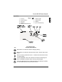
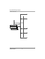
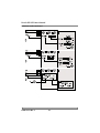
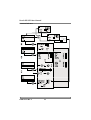
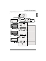
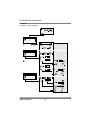
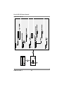
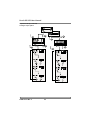
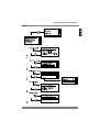
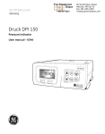
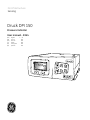
GE Infrastructure
Sensing
Druck DPI 150
Pressure Indicator
User manual - K344
[EN]
[FR]
[DE]
[IT]
[PT]
[ES]
English
French
German
Italian
Portuguese
Spanish
1 ..... 20
TBA
TBA
TBA
TBA
TBA
FS
20.000
Indicator
H
»
T
12.875
settings
bar g
Approved Service Agents
To find the approved agents for the servicing of GE products:
www.gesensing.com
Druck DPI 150 User Manual
General Introduction
This manual provides operating instructions for the DPI 150 Pressure
Indicator compatible with the requirements of operating the instrument.
Safety
The manufacturer has designed this equipment to be safe when operated
using the procedures detailed in this manual. The user must not use this
equipment for any other purpose than that stated.
This manual contains safety and operating instructions that must be
followed to make sure of safe operation and to keep the equipment in a safe
condition. The safety instructions are either warnings or cautions issued to
protect the user and the equipment from injury or damage. Use suitably
qualified personnel and good engineering practice for all procedures in this
manual.
Pressure
Do not apply pressure greater than the maximum working pressure stated
in the specification.
Technical advice
For technical advice contact the manufacturer or subsidiary.
Supervisor Security for the Druck DPI 150
GE strongly advise protection of the set-up menus in this equipment.
Unauthorised access to the supervisor and calibration menus can result in
degraded performance, incorrect settings and inaccuracies. The factory set
PIN are as follows:
Supervisor set-up - 0268 press MENU OK
Calibration set-up - refer to Service Manual K382
Codes can be changed to another code of 4 digits; entering 0000 disables
this security facility.
Symbols
The following symbols mark this equipment:
Refer to the manual.
This product meets the essential requirements of the
relevant EC directives.
i
K344 Issue No. 2
Druck DPI 150 User Manual
ABBREVIATIONS
The following abbreviations are used in this publication.
Note: Abbreviations are the same in the singular and plural.
abs
BSP
CAS
°C
const
DMM
DPI
esc
°F
g
(h)
absolute
British Standard Pipe (thread)
calibrated airspeed
degrees Celsius
constant
Digital multimeter
digital pressure indicator
(GE product)
escape
degrees Fahrenheit
gauge
hour
lbs
m
mbar
mm
pounds
metre
millibar
millimetre
mmH O millimetres of water
MWP maximum working pressure
NPT National Pipe Thread
2
PIN
personal identification number
psi
pounds per square inch
Ref.
reference
RS232 serial interface communication
standard
IDOS
intelligent digital output sensor
SCPI standard commands for programmable
(GE product)
instruments
IEEE 488 institute of electrical and electronic (s)
seconds
engineers standard 488 data
inHg
inches of mercury
TAS true airspeed
kg
kilogram
TBA to be advised
kts
knots
CONTENTS
Title
page
Approved service agents ......................................................... inside front cover
Introduction .................................................................................................... 1
Specification ............................................................................ 1
Installation ........................................................................................................ 2
Connections............................................................................... 3
Analogue Output Option ............................................................ 4
Panel mounting.......................................................................... 4
Bench stand............................................................................... 5
Operation.......................................................................................................... 7
Select mode menu..................................................................... 8
Indicator mode ........................................................................... 9
User set-up ..............................................................................11
Pressure leak test .................................................................... 12
Airspeed leak test .................................................................... 13
Airspeed................................................................................... 14
Mach ........................................................................................ 15
Supervisor set-up..................................................................... 16
Status....................................................................................... 19
Associated publications
The following e-documents can be downloaded from www.gesensing.com,
available from February 2005 onwards.
SCPI Communications Manual................................................................... K381
Calibration Instructions ............................................................................... K382
K344 Issue No. 2
ii
Druck DPI 150 User Manual
Introduction
The Druck DPI 150 high accuracy, single-range pressure indicator uses the
Druck IDOS sensor to produce pressure readings in units of pressure
measurement and aeronautical units.
The instrument is contained in a moulded plastic case with integral rubber
feet for workbench surface use. Function keys, on the front panel, allow the
user to access an operating menu and set-up menu. Two more menus,
supervisor and calibration, allow the user to change the PIN codes,
communications settings and display language and for calibration of the
pressure sensor. A four digit PIN code protects both these facilities. The
electrical and pressure connections are located on the rear panel.
The instrument is supplied, as standard, with a RS232 data interface. Options
available include an IEEE 488 interface, an analogue output, a barometric
reference, negative calibration, external sensor and panel mount kit.
Specification
Conformity
Safety ...................................................................................... EN61010
EMC emission ......................................................................... EN61326
EMC immunity......................................................................... EN61326
Gauge pressure ranges
....................................................................25, 70, 200, 350, 700 mbar
........................................1, 2, 3.5, 7, 10, 35, 70, 100, 135 and 200 bar
Absolute pressure ranges (using option E, barometric reference)
..................... add atmospheric pressure to the above gauge pressures
Maximum working pressure
0 to 350 mbar .................................................................. 2.0 x full-scale
0.7 to 2 bar, 3.5 to 70 bar, >100 bar ............................... 1.2 x full-scale
Precision
(includes non-linearity, hysteresis, repeatability and temperature effect between
18°C and 28°C [65° to 82°F]
below 1 bar....................................................................0.03% full-scale
1 bar to 200 bar.............................................................0.01% full-scale
Stability below 1 bar ............................................0.02% of reading/year
Stability above 1 bar............................................0.01% of reading/year
Option E, barometric reference
Pressure range .............................................. 750 to 1150 mbar absolute
Precision ................................................................................0.15 mbar
Accuracy
(includes non-linearity, hysteresis, repeatability and temperature effect
between 5°C and 50°C [41° to 120°F]
Stability...........................................................................0.15 mbar/year
1
K344 Issue No. 2
Druck DPI 150 User Manual
Environmental
Temperature
Operating ....................................................... 5° to 50°C (41° to 122°F)
Calibrated............................................................................ 23°C (74°F)
Storage.........................................................-20° to 60°C (-4° to 140°F)
Humidity ..................................complies with Def. Stan. 66-31 8.6 cat 3
Vibration ..................................complies with Def. Stan. 66-31 8.4 cat 3
Shock ....................................mechanical shock conforms to EN 61010
Pressure connections (female): ................................... G1/8 or 1/8 NPT
Weight (approximate): ....................................................... 1 kg (2.2 lbs)
Dimensions
Length ............................................................................. 195 mm (7.7”)
Width ............................................................................... 185 mm (7.2”)
Depth................................................................................. 75 mm (3.0”)
Analogue Option Electrical Specification
Isolated Voltage Output:Output Impedance....................................................................... 5 Ohm
Maximum Load Capacitance.........................................................10 nF
Isolated Current Output:Maximum Load Impedance..................................................... 900 Ohm
Maximum Load Capacitance.........................................................10 nF
Accuracy
(including pressure measurement uncertainty)
All voltage and current ranges ....±0.05 % FS (18° to 28°C, 12 months)
Update rate ...................................................... 30 updates per second
Installation
Key to
1 power supply
2 external sensor connector
UPM or UPM-P
3 IEEE 488 (option)
K344 Issue No. 2
4
5
6
7
RS232 connector
G1/8 or 1/8 NPT gauge pressure connector
G1/8 or 1/8 NPT barometric pressure connector
analogue output connector (option)
2
Druck DPI 150 User Manual
Connections
Note:
1.
Switch off the power supply before connecting or disconnecting the
instrument. Isolate the pneumatic supply pressures and depressurise
the pipes before connecting or disconnecting the instrument.
Use an appropriate sealing method for all pressure connections.
Method of connection 1/8 BSP (G1/8)
1/8BSP
1/8BSP
* bonded seal
bonded seal
recommended method
alternative method below 100 bar
*mandatory method 100 bar and above
Connections for gauge operation
Connections for barometric option
2.
Before use, make sure the SELV power adaptor supplied with the
instrument is correct for the power supply voltage. The Safety Extra
Low Voltage (SELV) power adaptor complies with EN61010 (including
safety requirements for laboratory instruments).
3
K344 Issue No. 2
Druck DPI 150 User Manual
Using other power adaptors
Responsibility of the User
A power adaptor, not supplied with the instrument, must comply with the
SELV safety requirements of EN61010:
Voltage AC or DC
11 to 26
3.
Power
10VA
Polarity
non-sensitive
Connect the power adaptor to the instrument and switch the power
supply on.
Analogue Output Option
Panel mounting
and 2a
A panel mounted instrument must have the rubber feet removed for the side
plates to be secured. The instrument fits into a panel cut-out, the side and
front plates of the panel mount kit (option C) secures the instrument to the
panel. It is important that a panel mount installation provides enough
circulation of air to cool the instrument.
Key to
1
2
3
4
K344 Issue No. 2
side plate
screw 45mm (not part of kit)
front plate
screw 3.5mm
4
Druck DPI 150 User Manual
Procedure
To fit this option requires a panel cut-out of the dimensions shown in 2a .
1.
Remove the rubber inserts in the feet of the instrument.
2.
Unscrew and remove two 45mm screws (2) attaching two feet on one
side of the instrument casing. Retain the two 45mm screws for the
next step.
3.
Fit the side plate (1) to the side of the instrument casing and secure
with the two 45mm screws.
4.
Repeat steps 2 and 3 for the other side plate.
5.
Locate the assembled instrument behind the cut-out panel and align
the four 3.5mm holes in the panel and the holes in the flanges of the
side plates (1).
6.
Locate the front plate (3) over the front of the protruding instrument
and secure the front plate with the four screws (4).
Bench stand
The bench stand lifts the front of the instrument providing a better angle of
display and key-pad access for the user.
Key to
1
2
3
4
5
stand
screw 45 mm
foot
clip, (left and right)
insert, rubber
5
K344 Issue No. 2
Druck DPI 150 User Manual
intentionally left blank
K344 Issue No. 2
6
Druck DPI 150 User Manual
Operation
Key to
1
2
3
4
5
esc key
menu OK key
zero key
hold key
down or decrease key
6
7
8
9
soft key right
soft key left
display
up or increase key
Display
Front Panel Keys
Key
Function and Comments
Steps back one selection without changing setting.
Steps back one selection sets and saves value. Selects and enters
menu.
Moves cursor up and down screen. Increases and decreases value
of selected digit.
Freezes displayed value, the instrument continues measuring but
does not display measured value until key pressed again.
Changes displayed value to 0.000 and stores the difference (offset)
in non-volatile memory of the pressure sensor.
7
K344 Issue No. 2
Druck DPI 150 User Manual
Select mode menu
K344 Issue No. 2
8
Druck DPI 150 User Manual
Indicator mode
9
K344 Issue No. 2
Druck DPI 150 User Manual
Indicator mode continued
K344 Issue No. 2
10
Druck DPI 150 User Manual
User Set-up
11
K344 Issue No. 2
Druck DPI 150 User Manual
Pressure leak test
K344 Issue No. 2
12
Druck DPI 150 User Manual
Airspeed leak test
(must be correctly enabled)
13
K344 Issue No. 2
Druck DPI 150 User Manual
Airspeed
(must be correctly enabled)
K344 Issue No. 2
14
Druck DPI 150 User Manual
Mach
(must be correctly enabled)
15
K344 Issue No. 2
Druck DPI 150 User Manual
Supervisor Set-up
K344 Issue No. 2
16
Druck DPI 150 User Manual
Supervisor set-up (continued)
Communications
17
K344 Issue No. 2
Druck DPI 150 User Manual
Supervisor set-up (continued)
Analogue output option
K344 Issue No. 2
18
Druck DPI 150 User Manual
Status
19
K344 Issue No. 2
Druck DPI 150 User Manual
intentionally left blank
K344 Issue No. 2
20