1
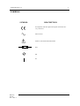
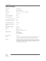
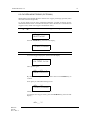
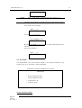
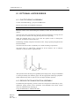
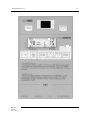
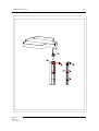
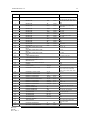
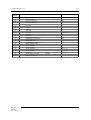
GUIDO RAYOS X, S.A.
1
INDEX
Disclaimer
Symbols
4
Specifications
5
Description
6
I.1
Patient Bed. Positioning of patient
6
I.2
I.V. Stand
6
I.3
Operation controls
10
Operation
10
II.1
To operate
10
II.2
To preheat
10
II.3
To heat
12
A
Air control mode
12
B
Servo control mode
13
II.4
Test timer
14
II.5
Oxygen monitoring (Optional)
15
II.6
Alarms
16
Air control mode
17
I
II
A
B
C
MAN-012
Sept.00
Ed. 1 / Rev. 3
1 Sensor alarm
17
2 Low temperature alarm
17
Servo control mode
18
1 Sensor alarm
18
2 Low temperature alarm
18
3 High temperature alarm
18
Power failure
19
II.7
Sensor activation and deactivation
19
II.8
Software language
20
II.9
Change of display type
21
II.10
On/Off Switch (SW) activation
21
II.11
Change of temperature alarm range (High/Low)
21
III
Maintenance
22
IV
Optional Accessories
23
IV.1
Phototherapy assembly
23
IV.2
Resuscitaion / Aspiration Assembly
23
NESTOMAT 6050
GUIDO RAYOS X, S.A.
2
Using the NEOPUFF Infant resuscitator
24
Cleaning
26
Maintenance
27
Functional schematic
28
Assembly diagram
28
Product specifications
29
IV.3
Shelves
30
IV.4
Other optional accessories
30
IV.5
Pulseoximetry module
30
Theory of operation
30
Front Panel Displays, Indicators and Keys
32
Alarms and indicators
33
Starting pulseoximetry
34
Measuring Pulse rate and SaO2
34
Setting and interpreting alarms
35
Adjusting the audio volume
35
V
Installation
36
VI
Service
39
VI.1
Instruments required
39
VI.2
Adjustments
39
A
Air temperature
40
B
Patient temperature
40
C
Oxygen concentration
40
Electronic diagram
42
Warranty
MAN-012
Sept.00
Ed. 1 / Rev. 3
NESTOMAT 6050
GUIDO RAYOS X, S.A.
3
DISCLAIMER
The safety devices and other controls provided in this equipment will perform reliably
when operated, maintained, and repaired in accordance with the instructions of this
manual.
Safety devices must be checked periodically and reset, repaired, or replaced as
necessary to ensure that they will operate reliably. Equipment and parts that are broken,
missing, badly worn, distorted or contaminated should be replaced with appropriate
GUIDO RAYOS X parts. The equipment or its components should not be modified
without the approval of the manufacturer.
The Manufacturer disclaims all responsability for any malfunction of this equipment
resulting from faulty operation, maintenance or repair, or if any of its components are
damaged or modified by anyone other than the manufacturer.
MAN-012
Sept.00
Ed. 1 / Rev. 3
NESTOMAT 6050
GUIDO RAYOS X, S.A.
4
SYMBOLS
SYMBOL
DESCRIPTION
In compliance with the required european norms CEI 6011-2 y CEI 601-1
Altern current
Atention, read the attached documents
Fuse
Off
On
MAN-012
Sept.00
Ed. 1 / Rev. 3
NESTOMAT 6050
GUIDO RAYOS X, S.A.
5
SPECIFICATIONS
Description
Radiant warmer
Model
NESTOMAT 6050
Alimentación
External AC : 220 V ó 125 V 50/60 Hz
Consumo
AC 0,25 A
Air control temperature
YES
Air temperature range
20 - 40 ºC
Air temperature digital readout
YES
Patient temperature control
YES
Patient temperature range
20 - 40 ºC
Patient temperature digital
readout
YES
Electrosthatic discharges
protection
Class : I
Type : BF
Fuses
Internal : 1 of 2A
External : 3 of 2A and 3 of 5A
Operation modes
Preheating
Air control mode
Servo control mode
Special functions
Oxygen
Alarms
Air sensor, skin sensor, oxygen sensor, high or low temperature, high or
low oxygen concentration, power failure, heating failure, motor error.
Optional
Phototherapy assembly, resuscitation/aspiration assembly, shelf monitors,
instruments shelf, holding assembly for two gas cyllinders, oxygen tent
hood with security valve, oxygen servoregulator, head frame, tray for
X-ray cassettes, drawer assembly.
MAN-012
Sept.00
Ed. 1 / Rev. 3
NESTOMAT 6050
GUIDO RAYOS X, S.A.
6
I. DESCRIPTION
The NESTOMAT Radiant Warmer provide a controlled source of radiant heat and
illumination. The heat is generated by one 500 watt quartz heat tube located above the
procedure table. The diverging energy emitted from the heating element is reflected
back toward the table surface with a parabolic reflector, this one focuses the diverging
waves of energy into parallel waves which are aimed toward the patient.
A lamphouse contains one standard 20 watt halogen lamp for illumination of the work
area.
I.1 PATIENT BED. POSITIONING OF PATIENT.
The infant should be placed on the procedure table directly on the mattress or with a
single cloth covering between the infant and the mattress cover. The NESTOMAT
Radiant Warmer has capability (ten locked positions) to place the head up or the head
down. Grasp the locking puller and pull outwards. Reposition the table and release
knob. The table will lock in position. Tilting puller is located under the front side of the
table.
The table has hinged, transparent panels on the sides and front wich can be positioned
upright to retain the infant or downward to ease accessibility to the infant. The air
temperature sensor is located at the rear panel.
A space for a X-ray cassette tray is provided at the patient platform; the radiant heater
shroud can be swivelled, during operation, to allow X-ray tratments, just only pushing
the knob located in the rear side of the shroud.
I.2 I.V. STAND.
The I.V. stand is mounted in the accessories rear rail, its height is adjustable.
I.3 OPERATION CONTROLS.
All operation controls are located on the front and the rear of the upper column.
MAN-012
Sept.00
Ed. 1 / Rev. 3
NESTOMAT 6050
GUIDO RAYOS X, S.A.
(1)
(2)
(3)
MAN-012
Sept.00
Ed. 1 / Rev. 3
7
HEAT/CALOR
Indication of heating device operation
ON/OFF
Switch the heating control
DISPLAY
Displays information, messages, etc.
SERVO
Patient Temperature operation mode
AIR
Air Temperature operation mode
START/STOP
Start / Stop operation
1 ... 0
Numerical sensitive keypad
ENTER
Confirm the set values
PRE
Preheating
O2
Select Oxygen readout (optional)
HIGH
High temperature alarm
LOW
Low temperature alarm
SENSOR
Sensor failure alarm
POWER
Power failure alarm
O2
High or Low oxygen alarm
SIL
Silence alarms
NESTOMAT 6050
GUIDO RAYOS X, S.A.
8
3
4
2
6
5
1
7
TEST TIMER
1
I/O
2
3
Indication of operation
LCD
4
5
Display
Indicator of timer operation
START/STOP
SIL.
Start / stop operation and silence alarm
6
Indication of time
7
Audible alarm. End of time
SENSORS
MAN-012
Sept.00
Ed. 1 / Rev. 3
Start up of the timer
AIRE/AIR
Air temperature sensor
% O2
Oxygen sensor (Optional)
PACIENTE/SKIN
Skin temperature sensor
NESTOMAT 6050
GUIDO RAYOS X, S.A.
1
I/O
Start up phototherapy
2
Treatment clock with zero reset
3
Total operation clock
4
Illumination lamp start up
5
6
MAN-012
Sept.00
Ed. 1 / Rev. 3
9
I/O
NESTOMAT On / Off switch
Power on led
NESTOMAT 6050
GUIDO RAYOS X, S.A.
10
II.OPERATION
IMPORTANT: BEFORE
TO USE THE
RADIANT WARMER
WITH A
PATIENT, IT IS NECCESSARY TO CHECK ITS GOOD PERFORMANCE CONDITIONS,
AS WELL AS THOSE FROM THE ACCESSORIES AND OPTIONS.
II.1 TO OPERATE
To start operation, plug the cord to the mains (check voltage) and press
the I/O switch located at the right side of the trolley.
Press the ON/OFF key at the front panel, the LCD will display "GUIDO
RAYOS X - VER. x.x", immediately afterwards the Radiant warmer will
perform a selftest of all its circuitry.
II.2 TO PREHEAT
CAUTION:BEFORE
TO USE THE
RADIANT WARMER
WITH THE
NEWBORN, PREHEAT THE UNIT FOR A BETTER COMFORT OF THE NEWBORN AND
AN ACCURATE PERFORMANCE.
PREHEATING PERIOD OF TIME DEPENDS ON
IF PREHEATING MODE IS NOT DESIRED, THE
OPERATION MODE, AIR OR SERVO, CAN BE DIRECTLY SELECTED.
ENVIRONMENTAL TEMPERATURE.
Pressing any key the LCD will display,
AIR=__._ ºC
SELECT MODE
Press the key “PRE” to start the preheating until to reach aproximately
the factory preset temperature (28 ºC). In the meantime the LCD will
display
AT=__._ ºC (__._ ºC)
PREHEATING
After “=“ symbol we can find present temperature.
It is possible to modify preset preheating temperature in order to reach a
nearly temperature of the normal operation temperature. Proceed with
following steps to change preset preheating temperature:
•
Turn on the radiant warmer:
GUIDO RAYOS X
VER X.X
MAN-012
Sept.00
Ed. 1 / Rev. 3
NESTOMAT 6050
GUIDO RAYOS X, S.A.
•
11
Press any key :
AIR=__._ ºC
SELECT MODE
•
Press AIR ,
AIR=__._ ºC
PSET AIR=28.0 ºC
•
Change old preset 28.0ºC temperature to new preheating temperature with
numerical keypad.
•
By pressing ENTER, you will confirm selection ,
AT=__._ ºC
PRESS START
•
Despite it is displayed “PRESS START”, you have to press “ENTER”. This is
because this is an special feature of NESTORET 5050 .
AIR=__._ ºC
SELECT MODE
•
Finally, press PRE. ,
AT=__._ ºC (__._)
PREHEATING
Once the preheating temperature is reached, the LCD will display "UNIT
READY", to be used within a patient, displaying the temperature inside
the Radiant warmer as well as advising to the medical personnel by
means of an acoustic signal. Then the Operation Mode should be selected
just afterwards the newborn is placed into the Radiant warmer.
IMPORTANT:BY
PRESSING AGAIN THE
PRE. KEY, THE LCD WILL
AIR TEMPERATURE (AT),
DISPLAY THE REGISTERED PARAMETERS, SUCH AS
PATIENT TEMPERATURE (ST).
NOTE: TO
II.5.
MAN-012
Sept.00
Ed. 1 / Rev. 3
SET
OXYGEN
AND
RELATIVE HUMIDITY
VALUES, SEE CHAPTER
NESTOMAT 6050
GUIDO RAYOS X, S.A.
12
II.3. TO HEAT
If Preheating Mode was not selected, proceed as follows:
Press any key, the LCD will display,
AIR=__._ ºC
SELECT MODE
To select the Operation Mode press AIR or SERVO key. AIR key
corresponds to Air Control Mode; SERVO key corresponds to Servo
Control Mode (patient skin temperature).
A) AIR CONTROL MODE:
NOTE: THE
DIGITAL DISPLAY INFORMS THE TEMPERATURE OF THE AIR
WHERE THE NEWBORN IS PLACED.
Pressing AIR key, the LCD will display ,
AIR=__._ ºC
PSET AIR=__._
By means the numerical keypad, set the heating device working range
between 20 and 40 ºC.
NOTE: WHEN
SETTING TEMPERATURE ENTER ALWAYS
CASE OF NO DECIMALS.
AS
EXAMPLE PRESS
3,
THEN
7,
3
DIGITS, EVEN IN
THEN
0
TO SET
37
DEGRESS.
Then press ENTER to confirm, the LCD will display ,
AT=__._ (__._)
PRESS START
Then press START to start the heating. The heat lamp will indicate the
operation of the heating device. By reaching the selected heating range,
the heating devices will modulate to keep the temperature stable.
The LCD will display the air registered temperature, as well as will
inform, too, the set temperature, displaying ACTIVED UNIT to inform
the heating device is in operation.
MAN-012
Sept.00
Ed. 1 / Rev. 3
NESTOMAT 6050
GUIDO RAYOS X, S.A.
13
AT=__._ ºC (__._)
UNIT ACTIVE
The selected heating range can be modified at any time by pressing
START/STOP and after ENTER key; you will find displayed following
message :
AIR=__._ ºC
SELECT MODE
Then set the new temperature by the keypad as previously explained and
confirm by pressing ENTER key. The LCD will display the messages
described above. Then press START key.
B) SERVO CONTROL MODE:
ATTENTION: BEFORE SELECTING SERVO CONTROL MODE
PROCEED TO PREHEAT THE RADIANT WARMER AS
EXPLAINED PREVIOUSLY IN THE II.2. TO PREHEAT
CHAPTER.
Before anything display on the screen following message :
AIR=__._ ºC
SELECT MODE
Press SERVO key, the LCD will display ,
SKIN=__._ ºC
PSET SKIN=__._
Set the patient temperature between 20 and 40 ºC by means of the
keypad, confirm by pressing ENTER key.
NOTE: WHEN
SETTING TEMPERATURE ENTER ALWAYS
CASE OF NO DECIMALS.
AS
EXAMPLE PRESS
3,
THEN
7,
3
DIGITS, EVEN IN
THEN
0
TO SET
37
DEGRESS.
The LCD will display ,
ST=__._ ºC (__._)
PRESS START
MAN-012
Sept.00
Ed. 1 / Rev. 3
NESTOMAT 6050
GUIDO RAYOS X, S.A.
14
NOTE: ST
MEANS PRESENT TEMPERATURE.
TEMPERATURE
IN BRACKETS
MEANS PRESET TEMPERATURE.
Then press START to start the heating. The heat lamp will indicate the
operation of the heating device. By reaching the selected patient
temperature, the heating device will modulate to keep the temperature
stable.
The LCD will inform the patient temperature and the selected one. By
displaying UNIT ACTIVE will inform the heating device is on
operation.
The set patient temperature can be modified at any time by pressing
START/STOP and after ENTER key; you will find displayed following
message :
AIR=__._ ºC
SELECT MODE
Then set the new temperature by the keypad as previously explained and
confirm by pressing ENTER key. The LCD will display the messages
described above. Then press START key.
ATTENTION: IF A MOMENTARY PAUSE WITHOUT
CHANGING THE SET PATIENT TEMPERATURE IS
REQUIRED, PRESS STOP KEY. PRESS START KEY TO
CONTINUE OPERATION. THE RADIANT WARMER WILL
OPERATE ON THE SAME OPERATION MODE AND
PARAMETERS ALREADY SET.
II.4 TEST TIMER.
This timer has a visual and audible alarms after 1, 5 and 10 minutes (1 + 4 + 5) since it
is switched on.
To operate the timer:
MAN-012
Sept.00
Ed. 1 / Rev. 3
•
Press I/O key to activate TEST TIMER device.
•
Press START/STOP key to iniciate first cycle (1 minute).
•
When the display shows 1 minute, the device will stop and alrmas (visual and
audible) will be activated.
•
Press START/STOP key to silence alarms and begin next cycle (4 minutes).
•
When the display shows 5 minutes, the device will stop and alrmas (visual and
audible) will be activated.
•
Press START/STOP key to silence alarms and begin last cycle (5 minutes).
•
When the display shows 10 minutes, the device will stop and alrmas (visual and
audible) will be activated. Press START/STOP key to silence alarms; the device
will be disconected automatically.
NESTOMAT 6050
GUIDO RAYOS X, S.A.
15
II.5 OXYGEN MONITORING (OPTIONAL).
NESTOMAT 6050 Radiant Warmer monitors the oxygen percentage (optional) when
used with a tent hood (optional).
To set the alarm level for above mentioned parameter, proceed as follows (do the
calibration with the sensor out of the tent hood, as it has to be done at a concentration of
oxygen of 21%, which is the oxygen concentration of air) :
NOTE: WHEN SELECTING YOU MUST START FROM “SELECT MODE” SCREEN.
AIR=__._ ºC
SELECT MODE
Press the O2/HUM key, the LCD will display ,
AIR=__._ ºC
1=OXYG, 2=HUMID
IMPORTATNT: OPTION 2=HUMID IS NOT OPERATIVE FOR RADIANT WARMERS.
To set the Oxygen range press 1, the LCD will display
AIR=__._ ºC
OX: 1=PRG, 2=CAL
Then, press 1 again ,
AT=__._ ºC (__._)
PRESET OX %=21.0
By means of the keypad set the desired value. Press ENTER key to
confirm.
Once again you will find following screen :
AIR=__._ ºC
1=OXYG, 2=HUMID
Finally press ENTER to confirm values.
To calibrate the Oxygen Sensor, press the O2/HUM. key, the LCD will
display ;
AIR=__._ ºC
MAN-012
Sept.00
Ed. 1 / Rev. 3
NESTOMAT 6050
GUIDO RAYOS X, S.A.
16
1=OXYG, 2=HUMID
NOTE:
DUE
TO THE WEAR OF THE
OXYGEN
CELL SENSOR IT IS
RECOMMENDED TO PERFORM PERIODICALLY ITS CALIBRATION PROCEDURES.
Check the Oxygen Sensor is pluged on the front panel and its housing is
not located inside the Tent Hood, allow to stabilize.
Press 1, the LCD will display,
AIR=__._ ºC
OX: 1=PRG, 2=CAL
Press 2, the LCD will display ,
OX CALIBR (21 %)
PRESS ENTER
By pressing ENTER, the Oxygen Sensor is already calibrated with a new
reference.
New screen displayed ;
AIR=__._ ºC
OX: 1=PRG, 2=CAL
II.6. ALARMS
The NESTOMAT 6050 Alarm System informs to the medical attendant of any
incidence may occur. The alarm is visible and audible.
NOMENCLATURE OF SYMBOLS IN ALARM
MESSAGES
+ Excess temperature alarm
-
Failing temperature alarm
= Temperautre O.K.
* Desactive sensor
A) AIR CONTROL MODE
MAN-012
Sept.00
Ed. 1 / Rev. 3
NESTOMAT 6050
GUIDO RAYOS X, S.A.
17
1. SENSOR ALARM:
In case of air sensor failure or it gets disconnected or out of range; the
SENSOR Alarm will activate the corresponding LED and buzzer, the
alarm cannot be silenced. The LCD will inform to the attendant
displaying ,
* ALARM *
AIR SENSOR
The Radiant warmer is now out of service. Call to any authorized Service
engineer.
2. LOW TEMPERATURE ALARM:
Is activated when temperature reaches aproximately 1 ºC below the preset
temperature (See paragrap II.10 to change preset temperature alarm
range). "LOW" alarm LED will lit, to silence acoustic alarm press
SILENCE key. The LCD will display
* ALARM *
AT - RH OX
The alarm can be silenced by pressing the SILENCE key. If SILENCE
was pressed and the alarm conditions remain during a period of ten
minutes, the alarm will be activated again.
3. HIGH TEMPERATURE
Is activated when the temperature reaches aproximately 1 ºC higher than
the preset temperature (See paragrap II.10 to change preset temperature
alarm range). "HIGH" alarm LED will lit and the LCD will display ,
* ALARM *
AT + RH OX
to silence acoustic alarm press SILENCE key. If SILENCE was pressed
and the alarm conditions remain during a period of ten minutes, the alarm
will be activated again.
Check if heat sources are close to the Radiant warmer location, if positive
keep them away. If the alarm is still effective unplug the unit from the
power source, remove the patient from the radiant warmer and call to the
authorised service engineer.
B) SERVO CONTROL MODE
1. SENSOR ALARM:
MAN-012
Sept.00
Ed. 1 / Rev. 3
NESTOMAT 6050
GUIDO RAYOS X, S.A.
18
Informs when a failure of the skin probe or if it gets disconnected or out
of range. The Alarm will activate the corresponding LED and buzzer.
The LCD will display ,
* ALARM *
SKIN SENSOR
being possible to silence. The Radiant warmer is now out of service. The
Radiant warmer can be used on Air Mode if no any circunstances or
alarms avoid it, in case it is absolutely needed switch to Air Operation
Mode and call to the authorized service engineer.
2. LOW TEMPERATURE
Is activated when temperature reaches aproximately 1 ºC below the preset
temperature (See paragrap II.10 to change preset temperature alarm
range). "LOW" alarm LED will lit and the LCD will display,
* ALARM *
ST - RH OX
to silence acoustic alarm press SILENCE key. If SILENCE was pressed
and the alarm conditions remain during a period of ten minutes, the alarm
will be activated again.
IMPORTANT: CHECK THE CONDITIONS OF THE PATIENT. CHECK THIERE IS
NOT AIR FLOW IN THE WARD. CHECK THE HEAT LAMP IS ON (THE
MICROPROCESSOR CONTROLS THE HEATING DEVICES); IF CONTRARY, UNPLUG
THE UNIT FROM THE POWER SOURCE, REMOVE THE PATIENT FROM THE
RADIANT WARMER AND CALL TO THE AUTHORISED SERVICE ENGINEER.
3. HIGH TEMPERATURE
Is activated when the temperature reaches aproximately 1 ºC higher than
the preset temperature (See paragrap II.10 to change preset temperature
alarm range). "HIGH" alarm LED will lit and the LCD will display ,
* ALARM *
ST + RH OX
to silence acoustic alarm press SILENCE key. HEAT lamp will switch
off. If SILENCE was pressed and the alarm conditions remain during a
period of ten minutes, the alarm will be activated again.
Check the conditions of the patient. Check if heat sources are close to the
Radiant warmer location, if positive keep them away.
If the alarm is still effective, unplug the unit from the power source,
remove the patient from the radiant warmer and call to the authorised
service engineer.
MAN-012
Sept.00
Ed. 1 / Rev. 3
NESTOMAT 6050
GUIDO RAYOS X, S.A.
19
C) POWER FAILURE
Is activated when failure of the power from the mains. The alarm circuit
includes a rechargeable battery and operation conditions of it must be
checked periodically.
To switch off the alarm operation, if desired, refer to chapter II.6.
"SENSORS ACTIVATION AND DEACTIVATION".
II.7. SENSORS ACTIVATION AND DEACTIVATION
The applications program of the NESTOMAT 6050 Radiant warmer allows to the user,
at any moment, to deactivate or activate the sensors of the monitored parameters, if
required for calibration procedures or non essential parameters cancellation (Oxygen
and/or Relative Humidity).
If the Radiant warmer is switched off, proceed as follows:
Press I/O switch, located at the side of the trolley.
Press ON/OFF key at the front panel. The LCD will display ,
GUIDO RAYOS X
VER X.X
then type sequentially:
•
SILENCE key
•
7388
•
SILENCE key.
ENTER
then the LCD will display ,
•
MAINT: 0 SW, 1 LNG
2 SEN, 3 DIS, 4 RNG
Press 2 key and the LCD will display all coded available sensors and their status as
follows,
1RH 2AT 3ST 4HT
5FA 6OX 7A2 8AI
(at the right side of each coded sensor "+" or "-" will display, meaning activated or
deactivated respectively)
(RH=Relative Humidity - Non operative, AT=Air Temperature, ST=Skin
Temperature,HT=Heating Device Temperature, FA=Fan - Non operative, OX=Oxygen
- Optional, A2 and A1 are auxiliary options for future implements)
To activate (+) or deactivate (-) press the corresponding figure key of the sensor.
Proceed with any sensor you want to activate or deactivate, then press ENTER to
MAN-012
Sept.00
Ed. 1 / Rev. 3
NESTOMAT 6050
GUIDO RAYOS X, S.A.
20
confirm.
The LCD will display ,
MAINT.: 0 SW, 1 LNG
2 SEN, 3 DIS, 4 RNG
pressing again ENTER the LCD will display the initial message. You can proceed to
set the Operation Mode, etc. as above described.
II.8. SOFTWARE LANGUAGE
The applications program of your NESTOMAT 6050 is delivered from factory in two
languages: english and spanish. At factory your radiant warmer has been preset to
english, if you want to switch to the language, proceed as follows:
Press I/O switch, located at the side of the trolley.
Press ON/OFF key at the front panel. The LCD will display ,
GUIDO RAYOS X
VER X.X
then type sequentially:
•
SILENCE key
•
7388
•
SILENCE key.
ENTER
then the LCD will display,
•
MAINT.: 0 SW, 1 LNG
2 SEN, 3 DIS, 4 RNG
Press 1 key
the LCD will display ,
1=ENGLISH VER
2=SPANISH VER
press the corresponding key to the selected language and confirm by pressing ENTER.
II.9. CHANGE OF DISPLAY TYPE
Press 3 key when applications programm is selected, display type will be activated,
MAN-012
Sept.00
Ed. 1 / Rev. 3
NESTOMAT 6050
GUIDO RAYOS X, S.A.
21
1 DISPL 16 CARS
2 DISPL 20 CARS
for LCD equipment press 1; for luminiscent display press 2.
II.10. ON/OFF SWITCH (SW) ACTIVATION
Press 0 key when applications programm is selected. The display will show:
WITH ON/OFF
WITHOUT ON/OFF
For equipments with ON/OFF switch on front panel keypad, press the ON/OFF key,
selecting WITH ON/OFF option.
II.11. CHANGE OF TEMPERATURE ALARM RANGE (HIGH /
LOW)
Press 4 key when applications programm is selected. The display will show:
RNG.TMP (0.1 ÷ 2.0)
R= __._ , H=
Preset value of temperature Range (R) (High / low) is 1 ºC. To this value corresponds a
hysteriris value (H) of 0,4 ºC.
To change the preset value (R) (between 0,1 ºC and 2,0 ºC), by means of the numerical
keypad, set the required value and press ENTER, the display will show the
corresponding hysteresis value (this value H can not be changed).
Then press ENTER again to accept the new values (R) and (H).
MAN-012
Sept.00
Ed. 1 / Rev. 3
NESTOMAT 6050
GUIDO RAYOS X, S.A.
22
III. MAINTENANCE
For routine cleaning, the entire unit may be wiped with a mild soap and water solution.
Avoid scratching painted surfaces. Do not use any cleaning agent containing an
abrasive material. When sterilization of exterior parts is necessary, wipe those parts
with a cold sterilization agent not including alcohols nor ethers.
MAN-012
Sept.00
Ed. 1 / Rev. 3
NESTOMAT 6050
GUIDO RAYOS X, S.A.
23
IV. OPTIONAL ACCESSORIES.
IV.1. PHOTOTHERAPY ASSEMBLY.
To turn on the Phototherapy , just press the I/O switch.
Electric starters allow an immediate swiching on.
WARNING: COVER INFANT'S EYES TO PROTECT FROM HIGH LIGHT LEVELS.
Reset the clock to zero when starting the treatment, to know the exact time for each
patient.
The total time clock will inform the total time that the Phototherapy is being used. In
such way the user will know how long the lamps have been operating.
When the treatment time is over or any time the operator wants to interrupt the
treatment, press I/O to switch off the unit.
Phototherapy assembly comprises four DULUX ® L lamps, specially designed for this
kind of treatment.
The electronic starters allow a reliability over 30.000 switching on operations.
2
The lamps emit at 8 µW/cm /nm, measured at 80 cm distance. For an effective
2
treatment, 4 µW/cm /nm are required at least.
After operation hours the lamps lose gardually their output power, being recommended
to check periodically the radiation power with the appropriate measuring equipment.
2
When radiation drops below 4 µW/cm /nm, the lamps should be replaced.
IV.2. RESUSCITATION/ASPIRATION ASSEMBLY.
Provided with peak inspiratory pressure control valve and pressure relief back-up valve,
manometer gauge, patient circuit. Flowmeter with humidifier and Venturi suction
device for aspiration with collecting jar.
Using the NEOPUFF™ Infant Resuscitator
MAN-012
Sept.00
Ed. 1 / Rev. 3
NESTOMAT 6050
GUIDO RAYOS X, S.A.
24
•
Please read and unsderstand the instructions fully before using the Neopuff
resuscitator and related accessories.
•
The Neopuff resuscitator is to be used only by persons trained in infant
resuscitation, It is responsibility of the purchaser to ensure that all users of this
device have been adequately trained in resuscitation techniques.
•
The Neopuff resuscitator should only be used after checking that correct
pressures will be delivered to the baby.
•
Ensure no smoking, naked flames or sources of ignition are present while the
unit is in use.
•
For connection to flow regulated oxygen or oxygen/air mixture only.
•
Minimum recommended operating gas flow 5 l/min. Do not attempt to use a
higher flow than 15 l/min.
•
The Maximum Pressure Relief can be adjusted up to a nominal 80 cm H2O, and
should only be done in exceptional circumstances by persons trained in infant
resuscitation. Do not attempt to set the Maximum Pressure Relief above 80 cm
H2O.
•
Use only a Fisher & Paykel T-piece.
1
Connect flow controlled oxygen or blender oxygen/air supply to the Neopuff
Gas Inlet port using oxygen inlet tubing.
2
Connect the patient supply tube to the Neopuff Gas Outlet port. If reusable
tubing is used, connect reusable T-piece to the patient, end of patient supply
tube.
3
Adjust the oxygen or oxygen/air flow between 5 and 15 l/min. Do not attempt to
use a higher flow that 15 l/min.
4
To check the Maximum Pressure Relief setting:
Conect the test lung to the T-piece, and check gas is flowing through the patient
MAN-012
Sept.00
Ed. 1 / Rev. 3
NESTOMAT 6050
GUIDO RAYOS X, S.A.
25
supply tube.
Check that the Circuit Pressure gauge reads zero with the Gas inlet disconnected.
Occlude the samall aperture in the Positive End Expiratory Pressure (PEEP) cap
on the T-piece with your thumb.
Turn the Inspiratory Pressure (PIP) control clockwise until the manometer
needle stops. This may require few rotations due to the fine thread pitch of the
valve. The manometer now indicates the current Maximum Pressure Relief
setting.
5
To adjust the maximum Pressure Relief:
Determine the current Maximum Pressure relief setting as described in step 4 .
Occlude the PEEP cap aperture with your thumb.
Rotate the Maximum Pressure Relief control to the desired Maximum Pressure
Relief setting.
6
To adjust the Inspiratory Pressure (PIP) valve:
Check the test lung is attached to the T-piece and occlude the PEEP cap aperture
with your thumb.
Adjust the Inspiratory Pressure contol knob to the desired peal inspiratory
pressure as displayed on the manometer.
7
To adjust the Positive End Expiratory Pressure (PPEP) valve:
Remove your thumb form the PEED cap aperture to allow gas to flow through
MAN-012
Sept.00
Ed. 1 / Rev. 3
NESTOMAT 6050
GUIDO RAYOS X, S.A.
26
the PEEP valve.
Adjust the PEEP cap to set the desired PEEP level as displayed on the
manometer.
8
Remove the tst lung from the T-piece. Fit the desired neonatal resuscitation mask
or endotracheal tube to the T-piece. The Neopuff resuscitator is now ready for
use.
9
Place the mask over the baby’s mouth and nose, or insert the endotracheal tube
into de baby’s airway.
10
To resuscitate:
Place your thumb over the PEEP cap aperture on the T-piece to produce an
inspiration.
Remove your thumb from the PEEP cap aperture on the T-piece to allow an
expiration.
Cleaning.
Ensure all oxygen and air supplies are turned off and disconnected from the Neopuff
before performing cleaning procedures.
Clean the Neopuff and accessories either weekly or between babies.
Do not use solvents, alcohol-based, or abrasive cleaning solutions.
Ensure all parts and accessories are checked before returning the device to service.
For ethylene oxide gases: Some carrier gases can cause stress craking and are not
Neopuff
Mask
Supply tube
T-piece
Steam autoclavable
136 ºC / 220 kPa / 4 minutes
✔
✔
✔
Steam autoclavable
120 ºC / 96 kPa / 15 minutes
✔
✔
✔
✔
✔
✔
✔
✔
✔
Ethylene Oxide Gas
Chemical liquid immersion
Wipe with soft damp cloth
MAN-012
Sept.00
Ed. 1 / Rev. 3
Test lung
✔
NESTOMAT 6050
GUIDO RAYOS X, S.A.
27
suitable. If in doubt check with chemical supplier.
For chemical liquid immersion: Some chemicals can be harmful to plastics. If in doubt
check with chemical supplier.
There are no user serviceable parts inside this device.
Maintenance.
Only qualified personnel should carry out service and maintenance procedures.
After any maintenance is completed, ensure the equipment is functioning corectly in
accordance with the published performance specifications.
Disassembly
•
Remove the front panel, fixed by four screws.
•
remove gas inlet and outlet connectors using torque driver and special adaptor.
•
Unscrew two manifold retaining screws at bottom of unit.
•
Disconnet monometer tube at top ot T-connector by pushing down on collar of
T-connector and pulling tube free.
•
Remove manifold assembly.
Replacing valve assembly
•
Disassemble Neopuff as aoutlined above.
•
Remove the inspiratory valve assembly using the C-spanner. Valve unscrews
anti-clockwise.
•
Fit new inspiratory valve assembly, tighten clockwise with C-spanner. The
inspiratory valve assembly can be identified by the shite restrictor plug located
at the bottom end of the valve.
•
remove maximum pressure relief valve assembly using C-spanner. Unscrews
anti-clockwise.
•
Fit new maximum pressure relief valve assembly, tighten clockwise with Cspanner. The masimum pressure relief valve has not restrictor plug.
•
Reassemble Neopuff and calibrate.
The manometer is not a serviceable item and must be replaced by Manometer kit
complete.
MAN-012
Sept.00
Ed. 1 / Rev. 3
NESTOMAT 6050
GUIDO RAYOS X, S.A.
28
Functional schematic
Gas outlet port
Gas inlet port
Maximum
Pressure
Relief Valve
Circuit
Presure
Manometer
Peak
Inspiratory
Pressure
Assembly diagram
MAN-012
Sept.00
Ed. 1 / Rev. 3
NESTOMAT 6050
GUIDO RAYOS X, S.A.
29
ITEM
REF.
1
616050011
Screw # 8 x 1” Csk Hd.
2
614040153
Screw # 8 x 1” Pan Hd.
3
500RD007
Manifold block
4
500RD519
Reservoir
5
693040741
End cap
6
614040309
Screw M8 x 20
7
693040706
Plug set of 5
8
693041436
Foot
9
DESCRIPTION
Panel plastic
10
043041057
Cover, max pressure relief.
11
500RD509
Connector 10 mm female gas inlet
12
Front fascia
13
500RD508
Connector 10 mm male gas outlet
14
500RD554
Manometer kit
15
693041444
Cap, inspiratory pressure valve
16
500RD506
Valve assemblies, pair
17
641040816
Column
18
614040117
Screw M4 x 8 Pan Hd
19
641040809
Handle
Product especifications
MAN-012
Sept.00
Ed. 1 / Rev. 3
Manometer Range
- 20 a 80 cm H2O
Maximum Pressure Relief
Between 70 and 84 cm
H2O
Caudal de entrada de gasesInput Gas flow Range
Between 5 and 15 l/min
Peak inspiratory pressure (@ 10 l/min)
2 to 80 cm H2O
PEEP (@ 10 l/min)
2 to 15 cm H2O
Recommended body weight range
Up to 10 kg
NESTOMAT 6050
GUIDO RAYOS X, S.A.
30
IV.3. SHELVES
Shelf for monitors.
Shelf for instruments.
Those shelves can be installed in both sides of the unit and its height can be regulated,
using the accessories rail placed on the rear of the column.
IV.4. OTHER OPTIONAL ACCESSORIES
Tray for X-ray cassettes.
Oxygen tent hod with security valve.
Holding assembly for two gas cylinders.
Drawers assembly.
IV.5 PULSEOXIMETRY MODULE.
The NESTOMAT 6050 (6100 Version) is a Neonatal Care Center that noninvasively
and continuously monitors arterial blood oxygen saturation (SaO2) and pulse rate.
SaO2 and pulse rate information is conveyed both visually and audibly. A custom high
contrast Liquid Crystal Display (LCD) with backlighting indicates the SaO2, pulse rate,
pulse signal strength and system messages. The tone generator "beeps" with each pulse
beat. The pulse "beep" momentarely changes to a lower tone "beep" when there is a
decrease in SaO2.
It has a flexible alarm system with audible and visual indi cators. The high and low
alarm limits are user adjustable. The audible alarm and pulse "beep" volume can be
adjusted or inhibited by the user.
Theory of Operation
The NESTOMAT 6050 (6100 Version) determines SaO2 and pulse rate
by passing two wavelengths of light, one red and one infrared, through
body tissue to a photodetector. Pulse identification is accomplished by
using plethysmographic techniques, and oxygen saturation measurements
are determined using spectrophotometric oximetry principles. During
measurement, the signal strength resulting from each light source depends on the color and thickness of the body tissue, the sensor placement,
the intensi-ty of light sources and the absorption of the arterial and
venous blood (including the time varying effects of the pulse) in the body
tissues.
The NESTOMAT 6050 (6100 Version) processes these signals, separating the time invariant parameters (tissue thickness, skin color, light
inten-sity and venous blood) from the time variant parameters (arterial
volume and SaO2) to identify the pulse and calculate the oxygen saturation. Oxygen saturation calculations can be performed because blood
saturated with oxygen predictably absorbs less red light than oxygen
depleted blood.
Since measurement of SaO2 depends on a pulsating vascular bed, any
condition wich restricts blood flow, such as use of a blood pressure cuff
MAN-012
Sept.00
Ed. 1 / Rev. 3
NESTOMAT 6050
GUIDO RAYOS X, S.A.
31
2
2
1
3
4
5
MAN-012
Sept.00
Ed. 1 / Rev. 3
6
10
7
8
9
NESTOMAT 6050
GUIDO RAYOS X, S.A.
32
or extremes in systemic vascular resistance, may cause an inability to
determine accurate pulse and SaO2 readings.
Front Panel Displays, Indicators and Keys.
1) SaO2 and Pulse Rate
Both are shown in large numerals. Smaller numerals show the high alarm
limit (above) and low alarm limit (below) each display.
2) Triangular Indicators
The triangular indicators point to the alarm limits to indicate the alarm is
selected for setting or flash to indicate the alarm limit has been violated.
"H" indicates high and "L" indicates low alarm limit.
3) Bargraph
The vertical bargraph has eight segments to display pulse activity and
strength. The bargraph is logarithmically scaled to indicate a wide range
of pulse strengths.
4) Low Pulse
The pulse level is low enough that the reading may be unreliable. May
indicate improper probe positioning.
Pulse Search
The unit is automatically adjusting signal processing and probe
LED drive levels to achieve acceptable signal levels, and is
interpreting the signal to detect the pulse.
Alarm
This indicates the alarm volume is being adjusted with the Up/
Down arrow keys.
Beep
This indicates the pulse "beep" volume is being adjusted with the
Up/Down arrow keys.
Alarm Silenced
Flashing indicates the alarm has been silenced with automatic two
minutes reset. Non-flashing (continuous) indicates the alarm has
been silenced indefinitely.
Beep Silenced
This is displayed for 1-2 seconds when the pulse "beep" volume is
adjusted to off.
Check Sensor
The probe is off the patient, needs to be repositioned, or is not
connected to the unit.
5) I/O
This key turns the Pulseoximetry Operating Mode on and off.
6) Display Light (Bulb)
This toggles the display backlight on and off.
7) Alarm Selec.
MAN-012
Sept.00
Ed. 1 / Rev. 3
NESTOMAT 6050
GUIDO RAYOS X, S.A.
33
Press Alarm Selec. to step through or set each of the four alarm limits.
Pressing a fifth time sets the monitor at none selected. If neither the
Up/Down arrows nor the Alarm Selec. key are pressed for aproximately
20 seconds, the system returns to none selected.
8) Up/Down Arrows
When an alarm limit is not selected, these keys increase/decrease either
the alarm volume (when the alarm is not silenced) or the pulse "beep"
volume (when the alarm is silenced). When an alarm limit is selected,
these keys control scrolling up and down through the alarms limits
setting.
9) Alarm Silence
Pressing this key turns the audible alarm off either for two minutes or
until the key is pressed again. Pressing and holding it for 3 seconds turns
the alarm off until the key is pressed again or the I/O is turned off and on.
10) Alarm LED
Indicates a patient or system alarm. The LED flashes or remains steady
depending on the alarm condition (See Alarms and Indicators Chapter).
Alarms and Indicators
1) Patient:
- Pulse beat detection: A short "beep" sounds each time a pulse beat is
detected. The volume is adjustable (including off) independently from the
alarm volume.
- Matched or Exceeded Alarm Limit: A two-tone alarm sounds (when the
alarm is not silenced), the red Alarm LED flashes, and the triangular
indicator for the violated alarm limit flashes.
- Low Pulse Amplitud: LOW PULSE is displayed.
- Drop in SaO2: A lower-tone "beep" sounds.
2) System:
- Probe Off patient or not connected to unit: A double "beep" sounds
every second (when the alarm is not silenced), CHECK SENSOR is
displayed and the red alarm LED lights continuously.
- Searching too long for Pulse: A double "beep" sounds every second
(when the alarm is not silenced), PULSE SEARCH is displayed and the
red alarm LED lights continuously.
Starting Pulseoximetry
WARNING: OPERATION
MAN-012
Sept.00
Ed. 1 / Rev. 3
OF
PULSEOXIMETRY
MAY BE AFFECTED IN THE
NESTOMAT 6050
GUIDO RAYOS X, S.A.
34
ELECTROMAGNETIC SOURCES, SUCH AS ELECTROSUREQUIPMENT. OPERATION MAY BE AFFECTED IN THE PRESENCE OF IMAGING EQUIPMENT, SUCH AS MAGNETIC RESONANCE IMAGING, COMPUTED
TOMOGRAPH DEVICES, ETC. SIGNIFICANT LEVELS OF DISFUNCTIONAL HEMOGLOBINS, SUCH AS CARBOXYHEMOGLOBIN OR METHEMOGLOBIN, WILL AFFECT
THE ACCURACY OF THE SAO2 MEASUREMENT. OPERATION MAY BE AFFECTED
IN THE PRESENCE OF HIGH AMBIENT LIGHT. SHIELD THE PROBE AREA IF NECCESSARY.
PRESENCE OF STRONG
GERY
Connect the patient cable to the PATIENT CABLE/PROBE connector at
the bottom of the front label of the equipment, just below the user
instructions.
Connect the probe to the Patient Cable.
Press the front panel I/O key. It performs a self test and lights all legends
when turned on.
Upon completion of the self test (aproximately 2 seconds), the unit will
automatically enter the monitoring mode.
NOTE: UPON POWER-UP THE UNIT DEFAULTS TO AN EIGHT (8) PULSE AVERAGING MODE FOR SAO2 MEASUREMENT AND AN EIGHT (8) SECOND AVERAGE FOR
PULSE MEASUREMENT.
Attach the Universal "Y" probe to the patient as shown in figure here
below, using adhesive strips as neccessary. When using the Universal
"Y" probe on the finger, attach the LED (light source) portion of the
sensor to the finger nail side of the finger.
Onc
e
probe is attached to the patient, allow several pulse beats for the monitor
to stabilize. Observe the pulse bargraph located on the LCD display. If
the pulse signal strength is low, the probe position may need adjustment.
Measuring the Pulse Rate and SaO2
After aproximately four or five pulse beats, the Pulse Rate and SaO2
values are displayed.
The pulse "beep" sounds with each pulse beat when the pulse tone is
enabled. A lower-tone "beep" sounds when a drop in SaO2 is detected.
Setting and Interpreting Alarms
MAN-012
Sept.00
Ed. 1 / Rev. 3
NESTOMAT 6050
GUIDO RAYOS X, S.A.
35
Alarms are still active while setting, but the "H" and "L" triangular
indicators do not flash for violated alarms. Both indicators act as a cursor
to identify the limit selected for adjustment.
Press the ALARM SELEC. key until the cursor is positioned at the alarm
parameter you are setting (High SaO2, Low SaO2, High Pulse Rate, Low
Pulse Rate).
Press the Up/Down arrow keys to increase or decrease the selected
alarma value. "--" in the alarm display indicates the alarm parameter is set
to OFF.
NOTE: THE ALARMS ARE NOT OVERLAPPING, YOU CANNOT SET THE LOW
ALARM HIGHER THAN THE HIGH ALARM OR THE HIGH ALARM LOWER THAN THE
LOW ALARM.
When an alarm limit is violated, a two-tone alarm sounds (when the alarm
is not silenced), the red alarm LED flashes and the triangular indicator for
the violated alarm limit flashes. The alarms stop when the alarm limit is
no longer violated.
Press the Alarm Slilence key to silence the alarm for two (2) minutes.
ALARM SILENCED flashes on the display. Press the Alarm Silence key
again to end the two minute alarm silence.
Press and hold the Alarm Silence key for three (3) seconds to silence the
alarm indefinitely. ALARM SILENCED is displayed continuously. Press
the Alarm Silence key again to end the indefinite alarm silence mode.
LOW PULSE is displayed when the pulse amplitude is low.
A lower-tone "beep" sounds when a drop in SaO2 is detected.
Adjusting the Audio Volume
MAN-012
Sept.00
Ed. 1 / Rev. 3
•
Alarms: Use the Up/Down arrow keys to adjust the audio alarm volume (when
not setting the alarm limits and the alarm is not silenced).
•
Pulse "Beep": Silence the audio alarms by pressing the Alarm Silence key (be
sure ALARM SILENCED is displayed). Now use the Up/Down arrow keys to
set the pulse beep volume reaches off.
NESTOMAT 6050
GUIDO RAYOS X, S.A.
36
V. INSTALLATION
To carry out the installation of NESTOMAT Radiant Warmer, following steps must be
executed:
MAN-012
Sept.00
Ed. 1 / Rev. 3
1.
Remove the rear lid of the column ! unscrewing the screws
".
2.
Unscrew the screws #.
3.
Introduce the radiant heater device with the cables $ through the bushing %.
4.
Place the radiant heater device, taking care that the blind holes & are in front of
the holes where the screws # are positioned.
5.
Replace the screws # and tighten them firmly.
6.
Connect the cable $ as per electric diagram in page 35.
7.
Replace the rear lid ! and replace the screws ".
NESTOMAT 6050
GUIDO RAYOS X, S.A.
MAN-012
Sept.00
Ed. 1 / Rev. 3
37
NESTOMAT 6050
GUIDO RAYOS X, S.A.
MAN-012
Sept.00
Ed. 1 / Rev. 3
38
NESTOMAT 6050
GUIDO RAYOS X, S.A.
39
VI. SERVICE.
Service must be performed by qualified and authorized service personnel. Call to the
manufacturer or its Agent for any service you may require.
VI.1 INSTRUMENTS REQUIRED.
To perform the adjustments properly the following instruments are required:
•
Digital Voltmeter (DVM).
•
Temperature and Oxygen Concentration Simulator (SIM60TO).
•
Screwdriver for adjusting (trimmer).
VI.2. ADJUSTMENTS
Before to perofrm the adjustments, check the voltage from the mains and from the poser
supply.
Input voltage should be 16 ± 2 V c.a. between 1 and 2 at J14.
Here below are detailed power referenced to ground (GND -TP8):
Power
Test point
+ 5V
TP6
+ 15 V
TP7
Once checked, perform the adjustment according to the instructions detailed here
below.
MAN-012
Sept.00
Ed. 1 / Rev. 3
•
Put DVM probes between GND-TP8 and TP3.
•
Twist P6 Potentiometer to read 0 Volts.
•
Put DVM probes between GND-TP8 and TP4.
•
Twist P7 Potentiometer to read 1.250 mV.
•
Deactivate sensors on the Service Menu.
•
Turn off the Incubator by pressing the I/O Switch located at the rear side of the
unit.
•
Release the connectors J1, J6, J12.
•
Connect on above connectors the wires from the Temperature Simulator
(SIM60TO) as follows:
Cable
Connector
Function
1
J7
Air temperature
2
J8
Patient temperature
3
J9
Oxygen concentration
NESTOMAT 6050
GUIDO RAYOS X, S.A.
40
Turn on the Radiant Warmer by pressing the I/O Switch located at the rear side of the
trolley.
Press the ON/OFF key.
Press three times the "PRE." key.
The LCD will display :
AT=00.0 PT=00.0
OX=00.0 RH=00.0
(AT: Air Temp., PT: Patient Temp., OX: Oxygen, RH: Non operative parameter)
A. Air Temperature
•
Place a jumper at J15.
•
Set Simulator switch at "0".
•
Set DVM probes between GND-TP8 and TP1. Twist P1 Potentiometer to read
between 2 to 4 mV.
•
Set Simulator switch at "40/99".
•
Twist P2 Potentiometer to read 40.0 ºC at the Air Temperature Display on the
Incubator Control.
•
Set Simulator switch at "18/21".
Twist P1 Potentiometer to read 18.0 ºC at the Air Temperature Display on the
Incubator Control.
Because adjustments are mutual interactive, therefore have to be repeated steps 3 and 6
until to get the correct value.
•
B. Patient Temperature
•
Set Simulator switch at "0".
•
Set DVM probes between GND-TP8 and TP2. Twist P5 Potentiometer to read
between 2 to 4 mV.
•
Set Simulator switch at "40/99".
•
Twist P4 Potentiometer to read 40.0 ºC at the Air Temperature Display on the
Incubator Control.
•
Set Simulator switch at "18/21".
Twist P5 Potentiometer to read 18.0 ºC at the Air Temperature Display on the
Incubator Control.
Because adjustments are mutual interactive, therefore have to be repeated steps 3 and 6
until to get the correct value.
•
C. Oxygen Concentration
MAN-012
Sept.00
Ed. 1 / Rev. 3
•
Set Simulator switch at "0".
•
Set DVM probes between GND-TP8 and TP5. Twist P9 Potentiometer to read
5 mV maximum.
NESTOMAT 6050
GUIDO RAYOS X, S.A.
41
•
Set Simulator switch at "40/99".
•
Twist P8 Potentiometer to read 99.0% at the Oxygen Concentration Display on
the Incubator Control.
•
Set Simulator switch at "18/21".
Twist P9 Potentiometer to read 21.0% at the Oxygen Concentration Display on
the Incubator Control.
Because adjustments are mutual interactive, therefore have to be repeated steps 3 and 6
until to get the correct value.
•
Once all adjustments are performed, proceed as follows:
•
Turn off the Radiant Warmer by pressing the I/O Switch located at the rear side
of the trolley.
•
Disconnet the jumper placed at J15 (point 1 - Air temperature).
NOTE: IT IS VERY IMPORTANT NOT TO FORGET TO DISCONNECT THIS JUMPER.
IF YOU DO NOT DISCONNECT IT AND WHEN THE UNIT IS WORKING, IT IS DICONNECTED THE AIR TEMPERATURE SENSOR THE UNIT WILL SWITCH OFF.
MAN-012
Sept.00
Ed. 1 / Rev. 3
•
Release the Simulator.
•
Connect all sensors wires on their locations.
•
Turn on the Radiant Warmer by pressing the I/O Switch and the ON/OFF key.
•
Activate on the Activation/Deactivation option all those available sensors on the
Radiant Warmer (Paragraph II.6).
•
Turn off the Radiant Warmer and then Turn on again to make all the above
effective.
NESTOMAT 6050
GUIDO RAYOS X, S.A.
42
ELECTRONIC DIAGRAM
PEGAR AQUI ESQUEMA DE
NESTOMAT 6050 REV 1.2,
QUE ESTA DENTRO DEL
MANUAL ORIGINAL EN EL
ARMARIO
MAN-012
Sept.00
Ed. 1 / Rev. 3
NESTOMAT 6050
GUIDO RAYOS X, S.A.
NUMBER
REF.
43
DESCRIPTION
VALUE
1
RESISTOR
4K7
1/4 W
2
RESISTOR
10K
1/4 W
3
4
RESISTOR
RESISTOR
1K
680 Ω
1/4 W
1/4 W
5
6
7
8
9
10
11
14
15
16
17
18
100K
75 Ω
18K7
470 Ω
2K2
487 Ω
1K5
330 Ω
2K
75K
22K
1/4 W
1/4 W
1/4 W
1/4 W
1/4 W
1/4 W
1/4 W
1/4 W
1/4 W
1/4 W
1/4 W
24
25
26
27
RESISTOR
RESISTOR
RESISTOR
RESISTOR
RESISTOR
RESISTOR
RESISTOR
RESISTOR
RESISTOR
RESISTOR
RESISTOR
SQUARE CONECTOR 2 PIN
R2,54
SQUARE CONECTOR 3 PIN
R2,54
SQUARE CONECTOR 2 PIN
R3,96
3 WAY BREAKAWAY
2 WAY BREAKAWAY
DOUBLE ROW TIRA 7 WAY
BREAKAWAY
BOARD 9 WAY BREAKAWAY
CHOKE
CAPACITOR
CERAMIC CAPACITOR
28
29
30
31
32
33
34
35
36
37
38
39
40
41
42
43
44
45
CERAMIC CAPACITOR
CERAMIC CAPACITOR
RADIAL CAPACITOR
RADIAL CAPACITOR
TANTALIUM CAPACITOR
RADIAL CAPACITOR
RADIAL CAPACITOR
RADIAL CAPACITOR
DIODE 1N4148
POTENCIOMETER
POTENCIOMETER
POTENCIOMETER
TRANSISTOR
TRANSISTOR
TRANSISTOR
TRANSISTOR
CRISTAL 12 MHZ
TEST POINTS
27 pF
10nF
1 µF
100 µF
10 µF
470 µF
2200 µF
4700 µF
44
45
CERAMIC RESISTOR
RECTIFICATOR BRIDGE
50 Ω
B80
19
20
21
22
23
MAN-012
Sept.00
Ed. 1 / Rev. 3
R6, R10,R15, R19, R20,
R21,R32,R39, R43,R44, R49
R5, R9, R14, R17, R24, R36,
R45
R22
R34, R35, R37, R40, R41,
R42, R48
R13, R16, R30, R31, R50
R3, R25
R2, R33
R7, R38
R11, R26, R27, R46
R1, R28
R8
R4
R47
R23, R18
R12
J2, J12, J4
J1, J6
J13, J14
J7, J8, J9, J10, J11
J15
J5
150 pF
100 nF
100 V
35 V
16 V
16 V
16 V
25 V
1K
5K
10K
BC 548
BC 557
BC 337
AD 580
4W
1500
CN3
CH1
C11
C1, C2, C4, C8, C9, C12,
C13, C14, C15, C18, C20,
CD1, CD2, CD5, CD6, CD7
C5, C6
C7
C3
C21
C10
C17
CD8, C19
C16
D1, D2,, D3, D4, D5, D6
P6, P7
P3
P1, P2, P4, P5, P8, P9
Q1, Q4, Q5, Q6
Q3
Q2
RE1
X1
TP1, TP2, TP3, TP4, TP5,
TP6, TP7, TP8
R53
PR1
NESTOMAT 6050
GUIDO RAYOS X, S.A.
NUM.
ORDEN
46
47
48
49
51
52
53
54
55
56
57
58
59
60
61
62
63
64
65
66
68
69
70
MAN-012
Sept.00
Ed. 1 / Rev. 3
REF.
44
DESCRIPCION
VALOR
RELAY
FUSEHOLDER
REGULATOR 7805
REGULATOR 7815
BUZZER
74C923
74HC573
ADC0801
CA 3140
AD202JN
CD4051
SOLID STATE RELAY
DISIPATOR L-200 20x20
FIXED RED LED
INTERMITTENT RED LED
FIXED GREEN LED
40 PIN SOCKET
16 PIN SOCKET
20 PIN SOCKET
8 PIN SOCKET
ARRAY
MICROPROCESATOR
DISPLAY CG57103
12 V
2A
8x4K7
DS5000
RL1
F1
RE 2
RE 3
Z1
U1
U6
U7
U3, U4, U9
U5
U8
RL2
RE2
L2, L3, L4, L5, L6, L8
L1
L7
U2
U8
U1, U6, U7
U3, U4, U9
AR1, AR2
U2
NESTOMAT 6050
GUIDO RAYOS X, S.A.
45
WARRANTY
GUIDO RAYOS X S.A. (hereinafter referred to as GRX) warrants that each
NESTOMAT Radiant Warmer will be free from defects in material and workmanship
under normal use and service for a period of one year from the date of delivery by GRX
to the first purchaser. If any such defect occurs during the warranty period, the aforesaid
purchaser should communicate directly with GRX agent. If returned, GRX's agent will
arrange for repairs or replacement within the terms of warranty. The defective
instrument should be returned properly packed, freight prepaid. Loss or damage in
shipment to GRX agent shall be at purchaser's risk. This same warranty is made for a
period of thirty days with respect to the expandable parts.
In no event shall GRX be liable for any incidental, indirect, or consequential damages
in connection with the purchase or use of the Radiant Warmer. This warranty shall not
apply to, and GRX shall not be responsible for any loss arising in connection with the
purchase or use of any such Radiant Warmer wich has been altered by anyone other
than an authorized GRX representative or altered in any way so as, in GRX's
judgement, to affect its stability or reliability or wich has been subject to misuse,
negligence, or accident, or wich has been used otherwise than in accordance with the
instructions furnished by GRX. This warranty is in lieu of all other warranties, express
or implied, and of all other obligations or liabilities on GRX's part, and GRX neither
assumes or authorizes any representative or other person to assume for it any other
liability in connection with the sale of such Radiant Warmer.
GRX disclaims all other warranties, express or implied, including any implied warranty
of merchant ability or of fitness for a particular purpose or application other than those
expressly set forth in the appropiate product labelling or user information manual.
MAN-012
Sept.00
Ed. 1 / Rev. 3
NESTOMAT 6050
GUIDO RAYOS X, S.A.
46
Manufactured by:
GUIDO RAYOS X, S.A.
Salcedo, 5
28034 Madrid (Spain)
Tel: +34 -91 - 358 16 25
Fax: +34 -91 - 358 08 69
e-mail: [email protected]
MAN-012
Sept.00
Ed. 1 / Rev. 3
NESTOMAT 6050
GUIDO RAYOS X, S.A.
MAN-012
Sept.00
Ed. 1 / Rev. 3
47
NESTOMAT 6050