1
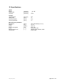
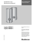
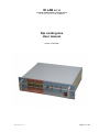
ID LAB s.r.o
Jordana Jovkova 3260, 143 00 Praha 4
tel: +420 241 764 697 e-mail: [email protected]
Dip coating box
User manual
Version 5 (09/2008)
c5std_manual_en.doc
page 1 of 20
c5std_manual_en.doc
page 2 of 20
Dip coating box
User and service manual
1 Content
1
2
3
4
5
Content............................................................................................................................................. 3
Safety instructions ............................................................................................................................ 4
Installation procedure....................................................................................................................... 4
Coater function ................................................................................................................................. 4
Coater description ............................................................................................................................ 5
5.1
Positioning guide....................................................................................................................... 5
5.2
Protective box ........................................................................................................................... 5
5.3
Electrical equipment.................................................................................................................. 5
6 Operation.......................................................................................................................................... 6
6.1
Automatic dipping cycle ............................................................................................................ 7
6.2
Manual (semiautomatic) dipping cycle...................................................................................... 8
7 Front panel controls ......................................................................................................................... 9
8 Menu - level 0 (root) ....................................................................................................................... 10
8.1
Root menu .............................................................................................................................. 10
9 Menu level 1 (accessible from root menu) ..................................................................................... 11
9.1
Menu Parameters 1 - viewing and modification of parameters 1 ........................................... 11
9.2
Menu Save - saving of actual parameters .............................................................................. 12
9.3
Menu Load - retrieving of actual parameters .......................................................................... 12
10
Menu level 2 (accessible from menu level 1) ............................................................................. 13
10.1
Menu Parameters 2 - viewing and modification of parameters 2........................................ 13
10.2
Menu Parameters 3 - viewing and modification of parameters 3........................................ 13
11
Menu level 3 (accessible from menu level 2) ............................................................................. 14
11.1
Menu Parameter Modification - modification of selected parameter................................... 14
12
Debug and calibration menu....................................................................................................... 17
12.1
Debug menu........................................................................................................................ 17
12.2
Calibration menu ................................................................................................................. 17
13
Remote control using serial line ................................................................................................. 18
13.1
Communication parameter setting for RS232 communication............................................ 18
13.2
Configuring computer for USB communication................................................................... 18
13.3
Coater remote control commands....................................................................................... 18
14
Maintenance and service............................................................................................................ 19
14.1
Maintenance........................................................................................................................ 19
14.2
Service ................................................................................................................................ 19
15
Specifications ............................................................................................................................. 20
c5std_manual_en.doc
page 3 of 20
2 Safety instructions
•
•
•
•
•
Before operating the device read this manual thoroughly.
Device is designed to be used indoors in normal environment. Usage of device outdoors or in
any environment with high risk of electrical injury or environment with risk of explosion is not
allowed.
For connections between control unit and coating box always use cables supplied by
manufacturer.
When operating device never put your hands to the coating area when the carriage is moving.
Never use device when it is damaged or performing unusual way. When you thing the device
is malfunctioning disconnect it from mains electricity and contact manufacturer for repair.
3 Installation procedure
After device delivery make visual check for any damage that might happen during shipping.
When installing coating box on a table:
• Place the coating box on a flat, rigid surface, so it is standing stable without any risk of
overturn.
When installing device on the wall:
• When installing device on the wall use four M8 threaded nuts, which are fitted into back side of
the frame.
• Mounting console is not supplied with the device.
• Wall on which the device is attached and the mounting console must be designed to withstand
at least 80Kg (four times the weight of the device).
4 Coater function
The coater is designed for coating of the flat shaped samples or similar objects with various
films. The method used is dipping solid, usually flat, samples into the liquid followed with smooth
pulling up.
The dipping cycle consist of several phases:
• transfer of the carriage to the upper position (initial position before dipping)
• time delay before dipping
• lowering the sample to the dipping bath to the lower position
• time delay before drawing up while sample is in the bath
• drawing the sample up to initial position
• whole process repeats if more than layer of liquid should be deposited.
The coater performes the whole dipping cycle automatically when switched into the automatic
cycle mode or simple cycle mode.
The coater performes dipping cycle step by step when switched into the manual mode (or
semiautomatic mode). In this mode the coater waits between each steps for operator command to
proceed.
All parameters of the dipping cycle are adjustable. Last set of parameters is stored and it is
available just after switching the coater on. Sets of parameters can be stored to selected memory
banks and reloaded for use. Up to 7 individual sets can be stored.
c5std_manual_en.doc
page 4 of 20
5 Coater description
The fundamental mechanical component of the coater is vertical mounted single-axis
positioning guide. The guide is overhung mounted on the protective box together with the electrical
equipment.
5.1
Positioning guide
Positioning gude consist of pair of guide rails, carriage equipped with linear ball bearings and
lead screw with zero-backlash nut. Guide rails as well as linear bearings with circulating balls are
made of stainless steel. Bearings are of sealed type with sealing rings, this feature avoids lubricant
leakage and allows operation without maintenance. The leading screw is also made of stainless steel
with teflon selflubricating low-friction film on the surface and it is operated without any lubrication. The
backlash witin the leading nut is automatically avoided due to splitted nut design with spring
preloading.
Tube shaped linear ball housings are mounted on common carrying plates. Carrying plates
are equipped with a set of threaded holes for flexible mounting of sample holders.
Leading screw drive consist of two-stage gearing with toothed belts, rotating parts are fitted
with sealed ball bearigs. The electric motor used is of dc current type with permanent magnet stator
and ironless armature featuring smooth operation and low inertia.
Motor is fitted with encoder mounted dicectly on the motor shaft. This rotary incremental
encoder has two-phase output possesing distinguished rotation direction as well as precision position
metering. Position metering is duplicated using multiturn precision potentiometer coupled to the
leading screw through worm gearing.This second metering device gives absolute position information
necessary for proper coater initialization after swithing on.
The driving mechanism is overhung mounted on the upper panel of the protective box.
5.2
Protective box
The protective box consist of stainless steel profile frame and acrylate glass walls. Back wall is
not removable and it has holes with removable flanges for ventilation connection etc. Front wall as well
as both side walls are designed as fully removable covers secured in mounted position with spring
loaded pivoted locks.
5.3
Electrical equipment
Electrical equipment includes microcontroller, LCD display and control elements on the front
panel, motor speed regulator with its own microcontroller and switching mode power supplies.
The control microcontroller performs several tasks. It operates the display. It acquires
commands from front panel pushbuttons and digital potentiometer. It communicates with the motor
regulator i.e. it generates commands for performing individual phases of the the dipping cycle. Also it
stores and retrieves parameter sets for selecting dipping cycles.
Front panel display is LCD type four-line alphanumeric device. The control elements on the
front panel are arranged into several sections - dipping cycle control, parameter adjustment, fast
positioning and context dependent pushbuttons reflecting actual state of the display.
The both speed and position motor regulator operates in the position feedback mode based on the
motor encoder incremental signal. The motor regulator also provides electrical position limitation,
traversing to reqiured position with requred speed and auxiliary function e.g. starting and trailing
ramps..
c5std_manual_en.doc
page 5 of 20
6 Operation
Operation consist of selecting all necesary parameters of the dipping cycle followed by
performing the cycle either automatically or semiautomatically step by step.
Moreover auxiliary operations can be performed, such as manual traversing to arbitrary
position, interrupting the cycle at arbitrary situation, storing and retrieving sets of dipping cycle
parameters to or from nonvolatile memory respectively.
Adjustable parameters of the dipping cycle - description:
- UP SPEED
- drawing-up speed (sample from dipping bath)
- lower to upper position traverse speed
- DOWN SPEED
- speed of dipping (sample down to bath)
- upper to lower position traverse speed
- UPPER POSITION
- initial position of the sample above bath before dipping
- LOWER POSITION
- final position of the sample in the bath
- UPPER DELAY
- holding time in the upper postition before dipping
- LOWER DELAY
- holding time in the lower position before drawing-up
- PARK POSITION
- position for manipulation with sample
- MANUAL SPEED
- speed setting used for following tasks:
- fast traverse both upward and downward
- moving to park position
- moving from park position to upper position before dipping
- EXPERIMENT MODE
- automatic or manual (step by step)
Comments to parameter adjustment:
Adjustment of all dipping cycle parameters is supposed before performing the cycle. Parameters can
not be changed once the cycle is in progress.
Speeds can be adjusted arbitrarily as well as delays and experiment / cycle mode.
Following rules apply concerning position adjustment:
• park position is supposed to be above upper position
• upper position is supposed to be above lower position
c5std_manual_en.doc
page 6 of 20
6.1
Simple dipping cycle
This mode does not require any user intervention once it is initiated using START button
The individual phases of the simple dipping cycle are as follows:
- start cycle
- initiated with pressing the START pushbutton
- traverse to upper position (preparation for dipping)
- target position is the UPPER POSITION
- traverse speed is the MANUAL SPEED
- time delay in the upper position
- time delay lasts according to UPPER DELAY parameter
- traverse to lower position (dipping the sample down to bath)
- target position is the LOWER POSITION
- traverse speed is the DOWN SPEED
- time delay in the lower position (sample holding time in the bath)
- time delay lasts according to LOWER DELAY parameter
- traverse to upper position (drawing the sample up from bath)
- target position is the UPPER POSITION
- traverse speed is the UP SPEED
- if more than one layer is deposited the cycle continues with time delay in upper position
- parking the carriage to park position
- target position is the PARK POSITION
- traverse speed is the MANUAL SPEED
6.2
Automatic dipping cycle
The individual phases of the automatic dipping cycle are as follows:
- start cycle
- initiated with pressing the START pushbutton
- parking the carriage to park position
- target position is the PARK POSITION
- traverse speed is the MANUAL SPEED
- the action takes place when carriage has not already been moved to park position
- manipulation delay
- no time limitation, coater waits for command
- manipulation delay abort
- initiated with pressing the STEP pushbutton
- traverse to upper position (preparation for dipping)
- target position is the UPPER POSITION
- traverse speed is the MANUAL SPEED
- time delay in the upper position
- time delay lasts according to UPPER DELAY parameter
- traverse to lower position (dipping the sample down to bath)
- target position is the LOWER POSITION
- traverse speed is the DOWN SPEED
- time delay in the lower position (sample holding time in the bath)
- time delay lasts according to LOWER DELAY parameter
- traverse to upper position (drawing the sample up from bath)
- target position is the UPPER POSITION
- traverse speed is the UP SPEED
- if more than one layer is deposited the cycle continues with time delay in upper position
- cycle finished
- carriage holds in the upper position without time limitation
- information on finished cycle appears on the display
Comments to cycle performing:
The operator can make consequent manipulation with samples easier after cycle is over using fast
traverse and / or park functions
The cycle can be interrupted any time before it is finished when pushbutton STOP is pressed
- information on this event appears on the display
c5std_manual_en.doc
page 7 of 20
6.3
Manual (semiautomatic) dipping cycle
The individual phases of the manual cycle are the same as they are in case of fully automatic cycle.
The coater waits before starting next dipping cycle phase until pushbutton STEP is pressed. So the
both delays (in upper position and lower position) are determined by user pressing the STEP button.
c5std_manual_en.doc
page 8 of 20
7 Front panel controls
Display section
Digital display
- presents various data according to current context
Pushbuttons
- context pushbutton with function dependent on current context
- function of each pushbutton is always displayed above or below relevant pushbutton
- pushbuttons without marked function have no effect in current context
Section „CYCLE“ - dipping control
Pushbutton „START“
- the pushbutton starts dipping cycle either automatic or semiautomatic
- the push button is functional from the root menu only
Pushbutton „STEP“
- the pushbutton aborts delay in park position while in automatic cycle
- the pushbutton starts next dipping cycle phase while in semiautomatic mode
- the push button is functional anytime during dipping cycle
Pushbutton „STOP“
- the pushbutton aborts dipping cycle either in automatic or in semiautomatic mode
- the pushbutton is functional anytime during dipping cycle
Section „SET“ - parameter adjustment
Electronic potentiometer
- the device is endless rotational encoder without mechanical stops
- rotating the device adjusts selected parameter
- rotating clockwise increases the setting of the selected parameter in steps
- rotating counterclockwise decreases the setting of the selected parameter in steps
- rotating while pushbutton „FINE“ is pressed changes the selected parameter
in smaller steps
- rotating while both pushbutton „FOLLOW“ is pressed and position type parameter
is selected causes the coater to follow current position setting immediately
- this feature makes the position adjustment easier
Section „ON/OFF“
Mains switch
- the device switches power to the coater on and off
c5std_manual_en.doc
page 9 of 20
8 Menu - level 0 (root)
8.1
Root menu
The coater enters the initial state when switched on, there is the root menu on the display:
COATER
Pos: XXX.XX
[ mm ]
Spd:
[ mm/m]
XXX
Parameters
Save
Load
Park
Information displayed:
- actual carriage position
- actual carriage speed
Active controls:
Pushbutton START
- starts dipping cycle with actual parameters i.e. with the last parameters used
or modified or retrieved from memory
Pushbutton FAST UP - fast traverse up
- carriage traverses up while pushbutton is pressed using speed MANUAL SPEED
Pushbutton FAST DOWN - fast traverse down
- carriage traverses down while pushbutton is pressed using speed MANUAL SPEED
Context pushbutton Parameters
- proceed to menu Parameters 1 to view or modify dipping cycle parameters
Context pushbutton Save
- proceed to menu Save for dipping cycle parameter saving into memory
Context pushbutton Load
- proceed to menu Load for dipping cycle parameter retrieving from memory
Context pushbutton Park
- starts carriage travers to park (manipulation) position
- travers stops automatically when park position is reached
- pushbutton STOP aborts traverse before reaching the park position
c5std_manual_en.doc
page 10 of 20
9 Menu level 1 (accessible from root menu)
9.1
Menu Parameters 1 - viewing and modification of parameters 1
This menu is accessible from root menu through context pushbutton Parameters:
Up
Down
Upper
Lower
speed
speed
position
position
XXX [ mm/m]
XXX [ mm/m]
XXX [ mm]
XXX [ mm]
Back
Next >>
Information displayed:
- setpoint of active speed up (drawing the sample up from the bath)
- setpoint of active speed down (dipping the sample down to the bath)
- setpoint of upper position (initial sample position before dippin into the bath)
- setpoint of lower position (sample position in the bath before drawing up)
Active controls:
Context pushbutton Back
- go back to the root menu
Context pushbutton Next >>
- proceed to menu Parameters/Next 2 to view or modify another dipping cycle parameters
Context pushbutton above the individual parameters
- proceed to menus Parameter Modification for modification of selected parameter
c5std_manual_en.doc
page 11 of 20
9.2
Menu Save - saving of actual parameters
This menu is accessible from root menu through context pushbutton Save:
1
2
3
4
Select file to SAVE parameters to
Back
5
6
7
Information displayed:
none
Active controls:
Context pushbutton Back
- go back to the root menu without saving modified parameters
Context pushbuttons for selection of the memory bank for actual cycle parameter to be save to
- pressing the pushbutton saves of the actual parameters to selected mamory bank
- memory banks are assigned with numbers 1 to 7
- after parameters are saved the root menu is automatically entered
9.3
Menu Load - retrieving of actual parameters
This menu is accessible from root menu through context pushbutton Load:
1
2
3
4
Select file to LOAD parameters from
Back
5
6
7
Information displayed:
none
Active controls:
Context pushbutton Back
- go back to the root menu without retrieving any parameters
Context pushbuttons for selection of the memory bank for actual cycle parameter to be retrieved from
- pressing the pushbutton retrieves of the actual parameters from selected mamory bank
- memory banks are assigned with numbers 1 to 7
- after parameters are retrieved the root menu is automatically entered
c5std_manual_en.doc
page 12 of 20
10 Menu level 2 (accessible from menu level 1)
10.1 Menu Parameters 2 - viewing and modification of parameters 2
This menu is accessible from menu Parameters 1 through context pushbutton Next:
Upper
Lower
Parking
Fast
delay
delay
position
speed
XXX [ s ]
XXX [ s ]
XXX [ mm ]
XXX [ mm ]
<< Prev
Next >>
Back
Information displayed:
- setpoint of upper position delay (before dipping the sample down to the bath)
- setpoint of lower position delay (holding sample in the bath before drawing up)
- setpoint of park position (manipulation position)
- setpoint of manual speed (speed setting for parking and fast traverse)
Active controls:
Context pushbutton Back
- go back to the root menu
Context pushbutton Next >>
- proceed to menu Parameters 3 to view or modify another dipping cycle parameters
Context pushbutton << Prev
- go back to menu Parameters 1 to view or modify another dipping cycle parameters
Context pushbutton above the individual parameters
- proceed to menus Parameter Modification for modification of selected parameter
10.2 Menu Parameters 3 - viewing and modification of parameters 3
This menu is accessible from menu Parameters 2 through context pushbutton Next:
Cycle
mode
(XXX)
Back
<< Prev
Information displayed:
- selected dipping mode (Auto nebo Manual)
- Auto means automatic performing of the whole dipping cycle
- Manual means performing of the cycle step-by-step
Active controls:
Context pushbutton Back
- go back to the root menu
Context pushbutton << Prev
- go back to menu Parameters 2 to view or modify another dipping cycle parameters
Context pushbutton above the individual parameters
- proceed to menus Parameter Modification for modification of selected parameter
c5std_manual_en.doc
page 13 of 20
11 Menu level 3 (accessible from menu level 2)
11.1 Menu Parameter Modification - modification of selected parameter
This menu is accessible from menus Parameters 1 to 3 through context pushbuttons:
Menus are similar for different parameters, examples below are typical.
Example for parameter of speed type:
Down speed
XXX.XX [ mm / m ]
< min , max >
Back
Fine
Set
Information displayed:
- actual setpoint of selected speed parameter
- acceptable setpoint limits of selected speed parameter
- setpoint is limited to predefined values
Active controls:
Context pushbutton Back
- go back to the root menu without parameter modification
Context pushbutton Fine
- while pressed the parameter changes in smaller steps
Context pushbutton Set
- adjusted value becomes valid and is saved to actual parameters memory
Electronic potentiometr SET (endless rotary encoder)
- rotating the device adjusts selected parameter
- rotating clockwise increases setting of the parameter in steps
- rotating counterclockwise decreases setting of the parameter in steps
c5std_manual_en.doc
page 14 of 20
Example for parameter of position type:
Actual position:
XXX [ mm ]
Upper position:
XXX [ mm ]
< min , max >
Back
Follow
Fine
Set
Information displayed:
- actual position
- actual setpoint of selected position parameter
- acceptable setpoint limits of selected positiom parameter
- setpoint is limited to predefined values
Active controls:
Context pushbutton Back
- go back to the root menu without parameter modification
Context pushbutton Follow
- while pressed the coater to follow current position setting immediately
- this feature makes the position adjustment easier
- speed uses parameter MANUAL SPEED
- pushbuttons Follow and Fine are mutually independent
- pushbuttons can be used indidually as well as simultaneously
Context pushbutton Fine
- while pressed the parameter changes in smaller steps
- pushbuttons Follow and Fine are mutually independent
- pushbuttons can be used indidually as well as simultaneously
Context pushbutton Set
- adjusted value becomes valid and is saved to actual parameters memory
Electronic potentiometr SET (endless rotary encoder)
- rotating the device adjusts selected parameter
- rotating clockwise increases setting of the parameter in steps
- rotating counterclockwise decreases setting of the parameter in steps
c5std_manual_en.doc
page 15 of 20
Example for parameter of delay type:
Upper delay
XXX [ s ]
< min , max >
Back
Fine
Set
Information displayed:
- actual setpoint of selected delay parameter
- acceptable setpoint limits of selected positiom parameter
- setpoint is limited to predefined values
Active controls:
Context pushbutton Back
- go back to the root menu without parameter modification
Context pushbutton Fine
- while pressed the parameter changes in smaller steps
Context pushbutton Set
- adjusted value becomes valid and is saved to actual parameters memory
Electronic potentiometr SET (endless rotary encoder)
- rotating the device adjusts selected parameter
- rotating clockwise increases setting of the parameter in steps
- rotating counterclockwise decreases setting of the parameter in steps
c5std_manual_en.doc
page 16 of 20
Example for parameter of dipping mode type:
Simple
Experiment mode
< Manual , Auto >
Back
Auto
Manual
Information displayed:
- none
Active controls:
Context pushbutton Back
- go back to the root menu without parameter modification
Context pushbutton Auto
- actual cycle type is set to automatic (one user intervention during cycle)
Context pushbutton Manual
- actual cycle type is set to semiautomatic (stepped)
Context pushbutton Simple
- actual cycle type is set to Simple (whole cycle on single START button press)
12 Debug and calibration menu
Debug menu and calibration menu are not intended to be used by an end user. These menus are for
factory settings only and their usage requires solid understanding of internal device structure.
Improper use may cause severe damage to the device.
12.1 Debug menu
Debug menu is accessible from root menu by holding upper-right context button for five seconds. In
this menu several debuging information is displayed on the display. If you accidentally enter this menu
you can safely go to root menu by pressing context button BACK (lower-left corner).
12.2 Calibration menu
This menu allows to calibrate position measurement of carriage. It is accessible from root menu by
holding second context button from the right at the top row, for ten seconds.
Calibration procedure must be done by manufacturer. Improper use of calibration procedure
may cause severe device damage. If you accidentally enter this menu you can safely go back to root
menu by pressing context button CANCEL (top-right corner). You can also switch the device off by the
mains switch and switch it on again.
c5std_manual_en.doc
page 17 of 20
13 Remote control using serial line
The coater provides one serial line compatible with RS232 standard and one USB port to enable
control of coater from external computer.
13.1 Communication parameter setting for RS232 communication
Serial communication port should be set as follows:
baud rate 9600 bd, no parity, 8 bits data, 2 stop bits
13.2 Configuring computer for USB communication
USB communication with coater is implemented using FT245 USB communication chip manufactured
by FTDI company. In order to use USB communication, appropriate device driver must be installed to
the host computer. Drivers are available on FTDI web pages for download. Download CDM driver for
the type of operating system you use and install it on your computer. Once the driver is installed you
can attach the coater device to the computer using USB cable. When the coater is switched on
computer automatically detects new device and a new virtual serial COM port is created. This port can
be used to communicate with the device same way as standard serial port.
13.3 Coater remote control commands
Each command must end with ASCII characters CR and LF (hex 0x0D and hex 0x0A).
Similarly the returned values are delimited with these characters.
Besides the response to commands some other data might appear on the serial line
(diagnostic messages etc.), those are not delimitet with above mentioned characters and therefore
they are easily distinguishable from responses to commands.
Coater repeats received command as a confirmation. Command G for reading the actual
position responds the carriage position in micrometers measured from bottom limit position.
A
S
P
Command
Activate
Parameter
none
Set speed speed
in mm/min
Go to
position
position
in microns
Returned value
none
(echoed command only)
none
(echoed command only)
none
(echoed command only)
U
Go up
none
none
(echoed command only)
D
Go down
none
none
(echoed command only)
T
Stop
none
G
Get
position
none
none
(echoed command only)
position
in microns
Activate remote control
mode using serial line
Set the carriage speed
Carriage traverses to
specified position and
then stops
Starts carriage traverse
up, proceeds until limit
or until T command is
received
Starts carriage traverse
down, proceeds until
limit or until T command
is received
Stops carriage traverse
Returns actual carriage
position. measured
from bottom limit
position.
Příklad
A<CR><LF>
S135<CR><LF>
P150000<CR><LF>
U<CR><LF>
D<CR><LF>
T<CR><LF>
G<CR><LF>
Examples:
Command:
Response:
S150<CR><LF>
S150<CR><LF>
speed set to 150 mm/min
speed setting confirmation
Command:
Response:
G<CR><LF>
G123456<CR><LF>
get carriage position
position 123 456 microns from bottom limit
c5std_manual_en.doc
page 18 of 20
14 Maintenance and service
14.1 Maintenance
- leading screw and guide rails surface cleaning from dust and other contaminants when necessary.
Use soft dry cloth.
14.2 Service
Service and adjustment is provided by supplier:
ID LAB s.r.o.
Jordana Jovkova 3260
143 00 Praha 4
phone: +420 241 764 697
+420 604 940 907
e-mail: [email protected]
c5std_manual_en.doc
page 19 of 20
15 Specifications
Speed
Range
Setting step
Accuracy
[ mm/min ]
[ mm/min ]
[ mm/min ]
1 to 300
1
±0.01
Position
Travel distance
Setting step
Accuracy relative
Accuracy absolute
[ mm rel ]
[ mm ]
[ mm ]
[ mm ]
250
1
±0.1
±1
[ mm ]
[ kg ]
[ V/Hz ]
[ VA ]
[ --- ]
[ --- ]
350 x 620 X 350 (š x v x h)
cca 17
220 / 50
max. 100
slow action T2A
stainless steel AISI304, teflon
mains cable
Miscellaneous parameters
Dimensions
Weight
Power
Power consumption
Fuses
Material used in box
Accessories
c5std_manual_en.doc
page 20 of 20