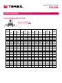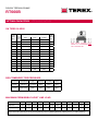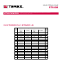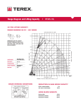
1
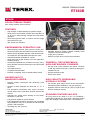
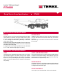
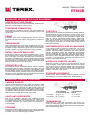
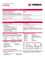
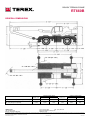
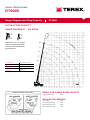
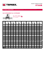
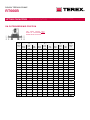
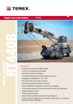
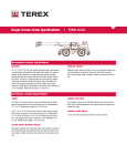
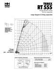
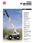
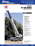
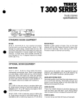
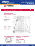
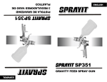
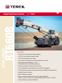
ROUGH TERRAIN RT660B Rough Terrain Crane Features RT660B FEATURES ▸ 60 tons (54 mt) maximum lifting capacity ▸ 106’ (32.4 m) maximum boom length ▸ 115’ (35 m) maximum tip height ▸ Four-section full power boom with single lever control ▸ Swingaway jib offsettable 0° or 20° ▸ Two-speed main and auxiliary winches ▸ Quick-reeving boom head and hook block ▸ Fully independent multi-position out and down outriggers ▸ Environmental operator’s cab optimizes load visibility and productivity ▸ Hydraulic joystick control ▸ Rated Capacity Indicator ▸ Easy to read load chart books include range diagrams ▸ Twelve month or 2,000 hour crane warranty and five year or 10,000 hours warranty on major weldments ROUGH TERRAIN CRANE RT660B RT660B ROUGH TERRAIN CRANES Max. Lifting Capacity: 66 tons (60 mt) FEATURES ▸ High strength, octagonal design to optimize weight. ▸ Single boom hoist cylinder provides boom elevation of -2° to 78° for easier reeving changes and close radius operation. ▸ Quick-reeving boom head; no need to remove wedge and socket from rope. ▸ 360° house lock standard. ENVIRONMENTAL OPERATOR’S CAB ▸ Rated Capacity Indicator (RCI) system including anti- two block system with automatic function disconnects. ▸ Deluxe sixway adjustable operator’s seat has mechanical suspension and adjustable head and arm rests. ▸ Sound and weather insulated for comfort. ▸ Upper and rear hinged window, front and upper antibreaking window. ▸ Armrest mounted dual axis controls for winch(s), swing, boom elevation and boom telescope; foot control pedal for throttle. ▸ Cab heater and A/C. ▸ Complete instrumentation. ▸ External, centralized, easy accessible electric panel. RUGGED EASY TO MANEUVER CARRIER ▸ Boxtype chassis construction with reinforcing cross members. ▸ Chassis is Terex designed and built with 4 x 4 x 4 drive. ▸ Full powershift transmission with torque converter; neutral safety start; three+three speeds forward and reverse. ▸ Hydraulic four wheel power steering for two wheel, fourwheel or crab steer. ▸ Fully air drum brakes on all four wheels. ▸ Fully independent hydraulic outriggers may be utilized fully extended to 23’ (7.2 m) and in their half extended position, with steel pads. ▸ Tail swing only 152” (3.85 m). TEREX Cranes 106-12th Street S.E. Waverly, Iowa 50677-9466 USA ▸ Standard electronic QSB6.7 200HP (149KW) TierIII ▸ ▸ compliant Cummins diesel engine. 79 gal (300 L) fuel tank. Earthmover style 26.50 x 25 P.R. tires standard. POWERFUL, TWO SPEED MAIN & AUXILIARY WINCHES, STANDARD ▸ 492 fpm (150 m/min) maximum line speed, 15,783 lb ▸ ▸ (7,200 kg) maximum line pull, 11,684 lb (5,300 kg) permissible line pull. Integral automatic brake. Winch drum rollers. HIGH CAPACITY, DEPENDABLE HYDRAULIC SYSTEM ▸ Two tandem gear pumps driven off the transmission. ▸ Combined system capability is 143 gpm (540 lpm). Hydraulic reservoir with 120 gal ( 550 L) capacity and full flow oil filtration system. STANDARD FEATURES INCLUDE 26’ (8 m) swing-on jib, offset 0° or 20° • Air conditioner • Cold weather starting aid • Work lights • Revolving amber light, 360° spotlight • Pintle hook front • Tire inflation kit TEL (319) 352-3920 FAX (319) 352-5727 EMAIL [email protected] WEB terex.com WE RESERVE THE RIGHT TO AMEND THESE SPECIFICATIONS AT ANY TIME WITHOUT NOTICE. THE ONLY WARRANTY APPLICABLE IS OUR STANDARD WRITTEN WARRANTY APPLICABLE TO THE PARTICULAR PRODUCT AND SALE. WE MAKE NO OTHER WARRANTY, EXPRESSED OR IMPLIED. ©TEREX CRANES, INC 2005 PRINTED IN U.S.A MAY 25, 2007 ROUGH TERRAIN CRANE RT660B Rough Terrain Crane Specifications RT660B STANDARD BOOM EQUIPMENT BOOM 33-106’ (10.3-32.4 m), four section full power boom. Separate extension of element 2 through double action hydraulic jack. Continuous proportional extension of elements 3 and 4 through double action hydraulic jack and inner chain-driven system. Extension under partial load possible. The boom is a highstrength octagonal design, welded out on the neutral axis, with anti-friction slide pads. A single boom hoist cylinder provides for boom elevation of -2° to 78°. Maximum tip height 115’ (35 m). BOOM HEAD Welded to fourth section of boom. Six resin load sheaves and one idler sheaves mounted on heave duty, anti-friction bearings. Quick reeving boom head. Provision made for side-stow jib mounting. OPTIONAL BOOM EQUIPMENT JIBS Jibs feature easy installation/stowage through use of spear type stowage system. Jibs utilize a single resin sheave mounted on antifriction bearing. Jibs are quickly offsettable at 0° or 20° by relocating two pins. 26’ (8 m) side stow swing-on one piece lattice type jib. Maximum tip height is 141’ (43 m). AUXILIARY BOOM HEAD Removable auxiliary boom head has single metallic sheave mounted on anti-friction bearing. Removable pin-type rope guard for quick reeving. Installs on main boom peak only. Removable is not required for jib use. HOOK BLOCK Six plastic sheaves on anti-friction bearings with hook and hook latch. Quick reeving design does not require removal of wedge and socket from rope. HOOK AND BALL 5,5 ton (5 mt) top swivel ball with hook and hook latch. ROUGH TERRAIN CRANE RT660B STANDARD UPPERSTRUCTURE EQUIPMENT UPPERSTRUCTURE FRAME All welded one piece structure fabricated with high tensile strength alloy steel. Counterweight is bolted to frame. TURNTABLE CONNECTION Swing bearing is a double row, ball type, with internal teeth. The swing bearing is bolted to the revolving upperstructure and to the carrier frame. SWING A hydraulic motor drives a double planetary reduction gear for precise and smooth swing function. Swing speed (no load) is two rpm. SWING BRAKE Heavy duty multiple disc swing brake. Negative type: spring applied, hydraulically automatically released. Brake electro-hydraulic release for direct alignment of boom along load vertical line. Manually operated 360° mechanical house lock is standard. RATED CAPACITY INDICATOR Rated Capacity Indicator with visual and audible warning system and automatic function disconnects. Display includes: boom radius, boom angle, boom length, allowable load, actual load and percentage of allowable load. Operator settable alarms provided for swing angle, boom length, boom angle, tip height and work area exclusion zone. Anti-two block system includes audio/visual warning and automatic function disconnects. OPERATORS CAB Environmental cab with all steel construction, optimum visibility, tinted safety glass throughout and rubber floor matting. The cab has a sliding door on the left side, window on the right side, Upper and rear hinged window, front and upper anti-breaking window. Acoustical foam padding insulates against sound and weather. The deluxe sixway adjustable seat is equipped with a mechanical suspension and includes head and arm rests. CONTROLS All control levers and pedals are positioned for efficient operation. Armrest mounted dual axis controls for winch(s), swing, boom elevation and boom telescope. Armrest swings up to improve access and egress. Steering column mounted turn signal, wiper, and horn controls. Dashboards include ignition, engine stop, lights, cab AC and heater, steering mode, parking brake, outriggers, telescope mode. Horn and swing brake release switches are mounted in the levers. Foot control pedals include service brake and accelerator. INSTRUMENTATION AND ACCESSORIES In-cab gauges include air pressure, bubble level, fuel, engine coolant temperature. Indicators include low air, low engine oil pressure, high transmission temperature and Rated Capacity Indicator. Accessories include fire extinguisher; light package including headlights, tail light, brake lights, directional signals, four-way hazard flashers, dome light and backup lights with audible backup alarm; windshield washer/wiper; skylight wipers; R.H. and L.H. rear view mirrors; dash lights; and seat belt. Circuit breakers protect electrical circuits. HYDRAULIC CONTROL VALVES Valves are mounted on the side of the upperstructure and are easily accessible. Valves have hydraulic operators and include one two spool valve for main and auxiliary winch and one three spool valve for boom movements together with one single spool valve for swing. Quick disconnects are provided for ease of installation of pressure check gauges STANDARD EQUIPMENT Auxiliary Winch, Electro-hydraulic Heater, hydraulically powered Air Conditioner, Hour counter, Work Lights, Rotating Beacon. STANDARD CARRIER EQUIPMENT CARRIER CHASSIS Chassis is Terex designed with four-wheel drive and four-wheel steer (4X4X4). Has box-type construction with reinforcing cross members, a precision machined turn table mounting plate and integrally welded outrigger boxers. Decking has antiskid surfaces, including between the frame rails lockable front tool storage compartment and access steps and handles on the left and right sides and on the front left and the rear right corners. AXLES AND SUSPENSION Rear axle is a planetary drive/steer type, oscillating mounted on the frame. Automatic oscillation lockouts that engage when the superstructure is swung 3° in either direction. Front axle is a planetary drive/steer type, rigid mounted to the frame for increased stability. STEERING Hydraulic four-wheel full power steering for two-wheel, fourwheel coordinated, or four-wheel crab steer is easily controlled by steering wheel. A rear axle centering light is provided. Turning Radius: (to CL of outside tire) Curb Clearance Radius Two-wheel: 48’ (14.6 mt) 39’ (11.82 mt) Four-wheel: 25’ 7” (7.8 mt) 17’ 5” (5.3 mt) TRANSMISSION Range-shift type power-shift transmission with torque converter has neutral safety start, three+three speeds forward and three+three speeds reverse provides wide ratio coverage. Automatic pulsating backup alarm. ROUGH TERRAIN CRANE RT660B STANDARD CARRIER EQUIPMENT (CONTINUED) TIRES MULTI-POSITION OUT AND DOWN OUTRIGGERS Wide earthmover (E3) style tread tires provide life and flotation. 26.5x25 P.R Fully independent hydraulic outriggers may be utilized fully extended to 23’(7,2 m) centerline to centerline or in their 1/2 extended position. Easily removable steel floats, each with an area of 514 in2 (3318 cm2), stow in the front of the outrigger boxes near their point of use. Complete controls and a sight leveling bubble are located in the operator’s cab. Split system fully air brakes on all four wheels, 20”x4.7” drum brakes on all wheels. WHEELS AND TIRES PARKING BRAKE Disk type wheels with full tapered bead seat rim. 150” (3.8 m) wheelbase. SERVICE BRAKES Springset, air released emergency/parking brake. On all wheels HYDRAULIC SYSTEM HYDRAULIC PUMPS Two tandem gear type pumps. Combined system capability is 143 gpm (540 lpm). Main winch pump ▸ 53 gpm (201 lpm) @ 3,046 psi (214 kg/cm2) Boom Hoist and Telescope Pump ▸ 47 gpm (178 lpm) @ 3,336 psi (235 kg/cm2) Power Steering and Winch Boost Pump ▸ 20 gpm (76 lpm) @ 2,176 psi (153 kg/cm2) Outrigger and Swing Pump ▸ 22.8 gpm (86 lpm) @ 2,321 psi (163 kg/cm2) MAIN WINCH SPECIFICATIONS Hydraulic winch with bent axis piston and planetary reduction gearing provides two-speed operation with equal speeds for power up and down. Winch is equipped with an integral automatic brake, smooth drum and standard cable roller on drum. Performance ▸ Max line speed (no load) ▸ First Layer ▸ Fourth Layer LO-Range 207 fpm (63 m/min) 242 fpm (74 m/min) ▸ Max. line pull-first layer ▸ Max. line pull-fourth layer ▸ Permissible line pull 16,1876 lb (7 200kg) 13,039 lb (5 800 kg) 11,915 lb (5 300 kg) ▸ ▸ ▸ ▸ ▸ Drum Dimensions 16.5” (419 mm) drum diameter 23.23” (590 mm) length 25.2” (640 mm) flange dia. Cable: 3/4” x 650’ (18 mm x 200 m) Cable type: 3/4” x (18 mm) 27Wx7, right lang lay HI-Range 364 fpm (111 m/min) 452 fpm (138 m/min) 10,116 lb (4 500 kg) 8,093 lb (3 600 kg) Drum Capacity Max. Storage: 820’ (250 m) on 5th layer OPTIONAL AUXILIARY WINCH Hydraulic 2-speed winch with bent axis piston motor, equal speed power up and down, planetary reduction with integral automatic brake, smooth drum and drum roller. ▸ ▸ ▸ Performance Max. line speed (no load) Fourth layer 318 fpm (97 m/min) Max. line pull First layer 11,240 lb (5 000 kg) Permissible line pull 8,543 lb (3 800 kg) FILTRATION Full flow oil filtration system with bypass protection includes 25 micron replaceable return line filter. HYDRAULIC RESERVOIR All steel, welded construction with internal baffles an diffuser. Provides easy access to filters and is equipped with an external sight level gauge. Capacity is 112 gal (424 L). Hydraulic oil cooler is standard. ENGINE SPECIFICATIONS ▸ ▸ ▸ ▸ ▸ ▸ ▸ ▸ ▸ ▸ ▸ Make and Model Type Displacement Rated HP Rated Torque Aspiration Air Filter Electrical System Alternator Battery (2) Fuel Capacity Cummins QSB6.7 6 cylinder 409 cubic inches (6.7L) 200 hp (149 kw) @ 2100 rpm 546 lb•ft (740 N•m) @ 1500 rpm turbocharged & charge air cooled dry type 24 volt 70 amp 12V 200Ah 850A 79 gal (300 L) PERFORMANCE (STANDARD ENGINE) Trans- Max. Grademission Forward Max. Tractive ability Gear Drive Speed Effort @Stall ▸Low 1 4-wheel 1.4 mph (2.3 kph) 70,924 lb (32 171 kg) >100% ▸Low 2 4-wheel 2.9 mph (4.6 kph) 34,145 lb (15 488 kg) 40.7% ▸Low 3 4-wheel 7.5 mph (12.1 kph) 12,522 lb (5 680 kg) 12.7% ▸High 1 2-wheel 4.0 mph (6.4 kph) 24,370 lb (11 054 kg) 27.3% ▸High 2 2-wheel 8.0 mph (12.9 kph) 11,735 lb (5 323 kg) 11.7% ▸High 3 2-wheel 19.9 mph (32.0 kph) 4,303 lb (1 952 kg) 3% All performance data is based on a gross vehicle weight of 89,300 lb (40 500 kg). 26.5x25 tires, 4x4 drive. Performance may vary due to engine performance. Gradeability data is theoretical and is limited by tire slip, machine stability, or oil pan design. ROUGH TERRAIN CRANE RT660B GENERAL DIMENSIONS UPPER FACING FRONT UPPER FACING FRONT WEIGHTS & AXLE LOADS GROSS WEIGHT LB FRONT REAR GROSS WEIGHT KG FRONT REAR Base Crane with 19,100 lb (8000 Kg) Counterweight 89,290 40,565 48,725 40,500 18,400 22,100 Add options: 26` *8 m( Swing/on Jib (Stowed) +1,325 +2,780 -1455 +600 +1260 -660 TEREX Cranes 106-12th Street S.E. Waverly, Iowa 50677-9466 USA TEL (319) 352-3920 FAX (319) 352-5727 EMAIL [email protected] WEB terex.com WE RESERVE THE RIGHT TO AMEND THESE SPECIFICATIONS AT ANY TIME WITHOUT NOTICE. THE ONLY WARRANTY APPLICABLE IS OUR STANDARD WRITTEN WARRANTY APPLICABLE TO THE PARTICULAR PRODUCT AND SALE. WE MAKE NO OTHER WARRANTY, EXPRESSED OR IMPLIED. ©TEREX CRANES, INC 2005 PRINTED IN U.S.A MAY 25, 2007 ROUGH TERRAIN CRANE RT660B Range Diagram and Lifting Capacity RT660B 66 TON LIFTING CAPACITY RANGE DIAGRAM 33` - 106` BOOM Dimensions are for largest factory furnished hook block and hook & ball, with anti-two block activated. COUNTERWEIGHT W/AUX. WINCH 17,637 LB BOOM LENGHT 33’-106’ OUTRIGGER SPREAD 23’ STABILITY PERCENTAGE ON OUTRIGGERS 85% ON TIRES 75% PCSA CLASS 10-210 CRANE WORKING CONDITIONS REDUCTION IN MAIN BOOM CAPACITY 26’ jib in stowed position 860 lb HOOK BLOCK WEIGHTS Hook and ball 239 lb 25T hook block (4 sheave) 690 lb 30T hook block (5 sheave) 888 lb 40T hook block (6 sheave) 913 lb ROUGH TERRAIN CRANE RT660B LIFTING CAPACITIES CAUTION: Do not use this specification sheet as a load rating chart. The format of data is not consistent with the machine chart and may be subject to change ON OUTRIGGERS FULLY EXTENDED USE THESE CHARTS ONLY WHEN ALL OUTRIGGERS ARE FULLY EXTENDED Load Radius (FT) Boom lenght 33’ Boom lenght 45’ Boom angle 360° (LB) Boom angle 10 67.5 120000 12 64.5 108400 15 58.0 85000 20 47.0 69400 25 23.0 44000 30 Boom lenght 58’ Boom lenght 69’ 360° (LB) Boom angle 360° (LB) 68.0 84800 73.0 72700 60.5 63900 67.5 59500 50.0 42900 60.0 44.0 37400 35 27.0 40 13.0 45 50 Boom lenght 94’ Boom lenght 106’ 360° (LB) Boom angle 360° (LB) Boom angle 360° (LB) Boom angle 72.0 48500 75.0 40700 77.5 34100 45100 65.5 38300 69.5 34100 73.0 29700 76.0 24900 56.0 38500 62.5 34300 67.0 31900 71.0 27700 74.0 23300 29700 47.5 26400 56.0 27100 61.5 24200 67.0 23800 70.0 20700 25300 42.5 23100 52.5 23800 59.0 22000 64.5 21800 68.0 18500 30.0 17800 45.0 18500 53.0 18000 59.5 17800 64.0 15600 22.0 15800 41.0 16300 50.0 16300 57.0 16000 62.0 14100 55 31.0 12500 43.5 12700 51.5 13400 57.5 12300 60 25.0 11200 40.0 11000 49.0 12300 55.0 11400 65 31.5 8100 43.0 10300 50.5 9700 70 26.0 7000 40.0 9200 48.5 9000 75 10.0 5500 32.5 7400 43.0 7700 80 29.0 6600 40.0 7000 85 16.0 5000 33.5 5700 90 25.0 4400 95 20.0 3900 100 13.0 3700 0° 2200 ² 0° 30800 0° 13200 0° 9900 Boom angle Boom lenght 82’ 0° 7000 0° 4400 0° 3300 360° (LB) ROUGH TERRAIN CRANE RT660B LIFTING CAPACITIES CAUTION: Do not use this specification sheet as a load rating chart. The format of data is not consistent with the machine chart and may be subject to change ON OUTRIGGERS MID POSITION USE THESE CHARTS ONLY WHEN ALL OUTRIGGERS ARE PINNED IN MID POSITION Load Radius (FT) Boom lenght 33’ Over Boom 360° front angle (LB) (LB) Boom lenght 45’ Over Boom 360° front angle (LB) (LB) Boom lenght 58’ Over Boom 360° front angle (LB) (LB) Load Radius (FT) 10 67.50 120000 95200 12 64.50 100800 83900 72.50 79300 78700 77.00 69800 69200 12 15 58.00 77800 66700 68.00 72000 66700 73.00 65200 64500 15 20 47.00 56800 37200 60.50 56800 37200 67.50 48500 37200 20 25 23.00 38100 21800 50.00 38100 21800 60.00 38100 21800 25 30 44.00 32600 17100 56.00 32600 17100 30 35 27.00 21800 11000 47.50 21800 11000 35 40 13.00 18100 9000 42.50 18100 9000 40 45 30.00 13100 5800 45 22.00 10800 4700 50 10 50 55 55 60 60 65 65 70 70 75 75 80 80 85 85 90 90 95 95 100 100 ² 0° 26400 13600 0° 16200 6800 0° 8300 2600 ² ROUGH TERRAIN CRANE RT660B LIFTING CAPACITIES CAUTION: Do not use this specification sheet as a load rating chart. The format of data is not consistent with the machine chart and may be subject to change ON OUTRIGGERS MID POSITION USE THESE CHARTS ONLY WHEN ALL OUTRIGGERS ARE PINNED IN MID POSITION Load Radius (FT) Boom lenght 69’ Over Boom 360° front angle (LB) (LB) 10 Boom lenght 82’ Over Boom 360° front angle (LB) (LB) Boom lenght 94’ Over Boom 360° front angle (LB) (LB) Boom lenght 106’ Over Boom 360° front angle (LB) (LB) Load Radius (FT) 10 12 15 20 12 15 76.50 53100 52400 20 72.00 46700 38300 75.00 38900 38500 77.50 32700 32400 25 65.50 36100 23100 69.50 31300 24000 73.00 27800 24400 76.00 23500 23300 25 30 62.50 32600 18000 67.00 28100 19000 71.00 25500 19400 74.00 22000 20100 30 35 56.00 23400 11900 61.50 23800 12800 67.00 21200 11200 70.00 18700 14200 35 40 52.50 19500 9900 59.00 20600 10800 64.50 19600 9400 68.00 17400 12200 40 45 45.00 14600 6800 53.00 15600 7700 59.50 15600 7900 64.00 14700 8500 45 50 41.00 12400 5600 50.00 13400 6200 57.00 13600 6800 62.00 13800 7300 50 55 31.00 9400 3800 43.50 10200 4400 51.50 10600 4700 57.50 11000 5200 55 60 25.00 8100 2800 40.00 9000 3500 49.00 9700 3800 55.00 10100 4400 60 65 ** 31.50 6900 2200 43.00 7400 2400 50.50 8300 3000 65 70 ** 26.00 6200 ** 40.00 6600 1900 48.50 7400 2600 70 75 10.00 4700 ** 32.50 5100 ** 43.00 6100 ** 75 80 29.00 4700 ** 40.00 5200 ** 80 85 16.00 3600 ** 33.50 4200 ** 85 90 25.00 3400 ** 90 95 20.00 2900 ** 95 13.00 2500 ** 100 0° 2000 ** ² 100 ² 0° 6100 ** 0° 4200 ** 0° 3000 ** ROUGH TERRAIN CRANE RT660B LIFTING CAPACITIES CAUTION: Do not use this specification sheet as a load rating chart. The format of data is not consistent with the machine chart and may be subject to change ON TIRES 26.5R25 Load Radius (FT) Max Boom Lenght (FT) 10 33 12 33 15 On Tires 26.5R25 Static static 2.5 MPH 360° Over front Over front Load Radius (FT) 48700 10 33800 42700 12 33 25500 33600 30000 15 20 33 16900 25700 22300 20 25 33 9500 18600 15800 25 30 45 6200 14700 13000 30 35 45 3400 9800 9300 35 40 45 2300 7800 7800 40 45 58 4600 4600 45 50 58 3400 3400 50 55 69 2700 2700 55 60 69 2300 2200 60 USE THESE CHARTS ONLY WHEN ALL OUTRIGGERS ARE FULLY RETRACTED RECCOMENDED TIRE PRESSURE Tire Size Make/Model Type Stationary 2.5 MPH Travel 26.5R25 “ADVANCE” 183B/203 A2 Conventional 83PSI 83PSI 51PSI 26.5R25 “MICHELIN” XADN 193B TL Radial 80PSI 80PSI 80PSI MAXIMUM PERMISSIBLE HOIST LINE LOAD Line Parts 1 2 3 4 5 6 7 8 9 10 11 12 Main Hoist 11915 23830 35745 47659 59574 71489 83404 95319 107234 119149 131064 142978 Auxiliary Hoist 8543 17086 25429 34172 42714 51256 59799 68342 76885 85427 93970 102513 MAIN HOIST WIRE ROPE: 3/4” ROTATION RESISTANT 27Wx7, MINIMUM BREAKING STRENGTH 59575 Lb. RIGHT LANG LAY. AUXILIARY HOIST WIRE ROPE: 5/8 ROTATION RESISTANT 27Wx7, MINIMUM BREAKING STRENGTH 42715 Lb. RIGHT LANG LAY. ROUGH TERRAIN CRANE RT660B LIFTING CAPACITIES CAUTION: Do not use this specification sheet as a load rating chart. The format of data is not consistent with the machine chart and may be subject to change ON OUTRIGGERS FULLY EXTENDED / JIB Load Radius (FT) Boom lenght 106 ft + Offset 26 ft Load Radius (FT) Boom angle 0° Offset Boom angle 25 78.00 14300 30 76.50 13600 35 73.50 12300 77.50 6800 35 40 72.00 11600 76.00 6600 40 45 69.00 10500 73.00 6300 45 50 67.50 10000 71.50 6200 50 55 64.50 9000 68.00 6000 55 60 63.00 8500 66.00 5900 60 65 59.00 7200 63.00 5700 65 70 57.50 6600 61.50 5400 70 75 54.00 5200 58.00 4700 75 80 52.00 4500 56.00 4500 80 85 48.00 3600 52.00 3500 85 90 44.00 2800 48.00 2800 90 95 42.00 2500 45.50 2500 95 100 40.00 2200 43.00 2200 100 105 35.00 1500 38.00 1500 105 20° Offset 25 30 ROUGH TERRAIN CRANE RT660B ROUGH TERRAIN CRANE RT660B General Notes RT660B GENERAL 1. Rated loads as shown on Lift Charts pertain to this machine as originally manufactured and equipped. Modifications to the machine or use of optional equipment or other than that specified can result in a reduction of capacity. 2. Construction equipment can be hazardous if improperly operated or maintained. Operation and maintenance of this machine shall be in compliance with the information in the Operator’s, Parts and Safety Manuals supplied with this machine. If These manuals are missing, order replacements from the manufacturer through your distributor. 3. These warnings to not constitute all of the operating conditions for the crane. The operator and job site supervision must read the OPERATORS MANUAL, CIMA SAFETY MANUAL, APPLICABLE OSHA REGULATIONS, AND SOCIETY OF MECHANICAL ENGINEERS (ASME) SAFETY STANDINGS FOR CRANES. 4. This crane and its load ratings are in accordance with POWER CRANE & SHOVEL ASSOCIATION, STANDARD NO.4 SAE CRANE LOAD STABILITY TEST CODE J765A, SAE METHOD OF TEST FOR CRANE STRUCTURE J1063 AND APPLICABLE SAFETY CODE FOR CRANES, DERRICKS AND HOISTS, ASME/ANSI B30.5 DEFINITIONS 1. LOAD RADIUS - The horizontal distance from the axis of rotation before loading to the center of the vertical hoist line or tackle with a load applied. 2. LOADED BOOM ANGLE - It is the angle between the boom base section and the horizontal, after lifting the rated load at the rated radius. the boom angle before loading should be greater to account for deflections. The loaded boom angle combined with boom length give only an approximation of the operating radius. 3. WORKING AREA - Areas measured in a circular arc about the centerline of rotation as shown in the diagram. 4. FREELY SUSPENDED LOAD - Load hanging free with no direct external force applied except by the hoist rope. 5. SIDE LOAD - Horizontal force applied to he lifted load either on the ground or in the air. 6. NO LOAD STABILITY LIMIT - The stability limit radius shown on the range diagrams is the radius beyond which it is not permitted to position the boom, when the boom angle is less than the minimum shown on the applicable load chart, because the machine can overturn without any load. 7. BOOM SIDE OF CRANE - The side of the crane overwhich the boom is positions when in OVER SIDE working position. SET-UP 1. Crane load ratings are based on the crane being leveled and standing on a firm, uniform supporting surface. 2. Crane load ratings on outriggers are based on all outrigger beams being fully extended or in the case of partial extension ratings mechanically pinned in the appropriate position, and the tires free of the supporting surface. 3. Crane load ratings on tires depend on appropriate inflation pressure and the tire conditions. Caution must be exercised when increasing air pressures in tires. Consult Operator’s Manual for precautions. 4. Use of jibs, lattice-type boom extensions, or fourth section pullouts extended is not permitted for pick and carry operations. 5. Consult appropriate section of the Operator’s and Service Manual for more exact description of hoist line reeving. 6. The use of more parts of line than required by the load may result in having insufficient rope to allow the hook block to reach the ground. 7. Properly maintained wire rope is essential for save crane operation. Consult Operator’s Manual for proper maintenance and inspection requirements. 8. When spin-resistant wire rope is used, the allowable rope loading shall be the breaking strength divided by five (5), unless otherwise specified by the wire rope manufacturer. 9. Do not elevate the boom above the angle shown in the Lift Charts unless the boom is positioned in-line with the crane’s chassis or the outrigger are extended. Failure to observe this warning may result in loss of stability. TEREX Cranes 106-12th Street S.E. Waverly, Iowa 50677-9466 USA OPERATION 1. CRANE LOAD RATINGS MUST NOT BE EXCEEDED. DO NOT ATTEMPT TO TIP THE CRANE TO DETERMINE ALLOWABLE LOADS. 2. When either radius or boom length, or both, are between listed values, the smaller of the two listed load ratings shall be used. 3. Do not operate at longer radii than those listed on the applicable load rating chart (cross hatched areas shown on range diagrams.) 4. The boom angles shown on the Capacity Chart give an approximation of the operating radius for a specified boom length.The boom angle, before loading, should be greater to account for boom deflection. It may be necessary to retract the boom if maximum boom angle is insufficient to maintain rated radius. 5. Power telescoping boom sections must be extended equally. 6. Rated loads include the weight of hook block, slings, and auxiliary lifting devices. Their weights shall be subtracted from the listed rated load to obtain the net load that can be lifted. When lifting over the jib the weight of any hook block, slings, and auxiliary lifting devices at the boom head must be added to the load. When jibs are erected but unused add two (2) times the weight of any hook block, slings, and auxiliary lifting devices at the jib head to the load. 7. Rated loads do not exceed 85% on outriggers or 75% on tires, of the tipping load as determined by SAE Crane Stability Test Code J765a. 8. Rated loads are based on freely suspended loads. No attempt shall be made to drag a load horizontally on the ground in any direction. 9. The user shall operate at reduced ratings to allow for adverse job conditions, such as: soft or uneven ground, out of level conditions, high winds, side loads, pendulum action, jerking or sudden stopping of loads, hazardous conditions, experience of personnel, two machine lifts, traveling with loads, electric wires, etc. (side pull on boom or jib is hazardous). Derating of the cranes lifting capacity is required when wind speed exceeds 20 MPH. The center of the lifted load must never be allowed to move more then 3* off the center line of the base boom section due to the effects of wind, inertia, or any combination of the two. *”Use 2’ off the center line of the base boom for a two section boom, 3’ for a there section boom, or 4’ for a four section boom.” 10. The maximum load which can be telescoped is not definable, because of variations in loadings and crane maintenance, but it is permissible to attempt retraction and extension if load ratings are not exceeded. 11. Load ratings are dependent upon the crane being maintained according to manufacturer’s specifications. 12. It is recommended that load handling devices, including hooks, and hook blocks, be kept away from boom head at all times. 13. Do not lift with outrigger beams positioned between the fully extended and intermediate (pinned) positions. CLAMSHELL, MAGNET, AND CONCRETE BUCKET SERVICE 1. Weight of clamshell or magnet, plus contents are not to exceed 6,000 lb or 90% of rated lifting capacities, whichever is less. For concrete bucket operation, weight of bucket and load must not exceed 90% of rated lifting capacity. TEL (319) 352-3920 FAX (319) 352-5727 EMAIL [email protected] WEB terex.com WE RESERVE THE RIGHT TO AMEND THESE SPECIFICATIONS AT ANY TIME WITHOUT NOTICE. THE ONLY WARRANTY APPLICABLE IS OUR STANDARD WRITTEN WARRANTY APPLICABLE TO THE PARTICULAR PRODUCT AND SALE. WE MAKE NO OTHER WARRANTY, EXPRESSED OR IMPLIED. ©TEREX CRANES, INC 2005 PRINTED IN U.S.A MAY 25, 2007