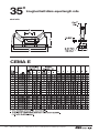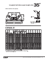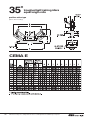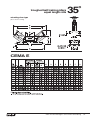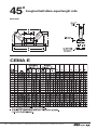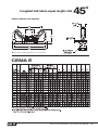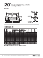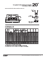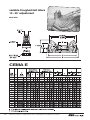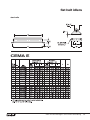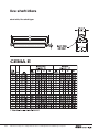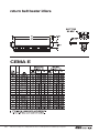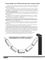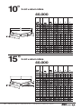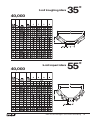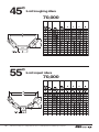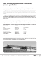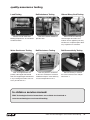
1
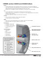
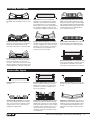
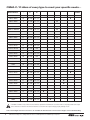
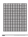
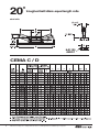
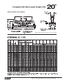
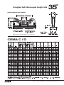
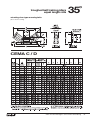
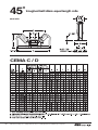
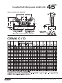
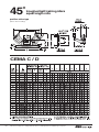
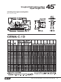
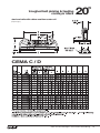
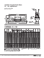
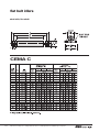
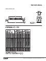
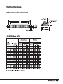
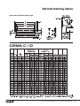
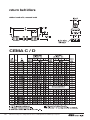
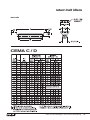
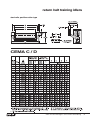
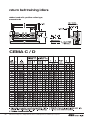
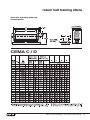
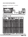
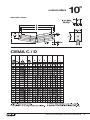
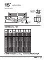
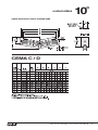
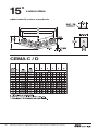
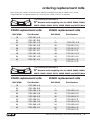
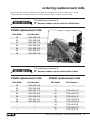
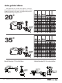
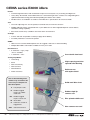
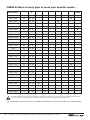
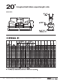
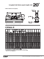
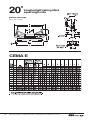
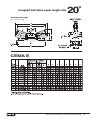
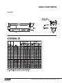
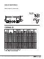
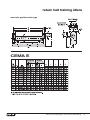
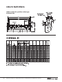
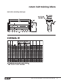
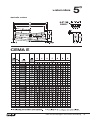
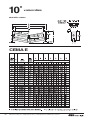
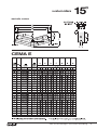
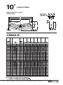
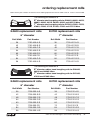
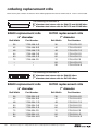
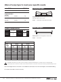
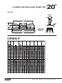
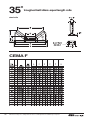
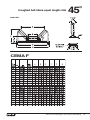
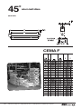
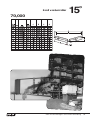
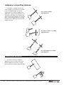
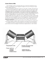
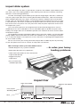
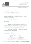
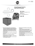
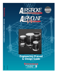
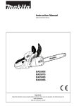
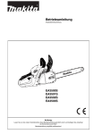
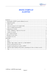
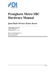
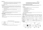
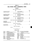
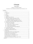
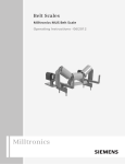
Belt Conveyor Idlers
8
© 2010 • FMC Technologies, Inc.
www.fmctechnologies.com/materialhandling
contents
belt conveyor idlers
FMC Technologies & Link-Belt®
The Driving Force of Industry Standards . . . . . . . . . . . . . . . . . . . . . . . . . . . . . . . . . . . . . . . . . . . 3
series C3000 and D3000 idlers
....................................4
replacement rolls for C3000 and D3000
. . . . . . . . . . . . . . . . . . . . 39
side guide idlers . . . . . . . . . . . . . . . . . . . . . . . . . . . . . . . . . . . . . . . . . . . . . . . . . . . . . . . . . . . 44
scale idlers . . . . . . . . . . . . . . . . . . . . . . . . . . . . . . . . . . . . . . . . . . . . . . . . . . . . . . . . . . . . . . . . . . . 45
series E4000 idlers . . . . . . . . . . . . . . . . . . . . . . . . . . . . . . . . . . . . . . . . . . . . . . . . . . . . . . . 46
replacement rolls for E4000 . . . . . . . . . . . . . . . . . . . . . . . . . . . . . . . . . . . . . . . . 79
series E4000HD
. . . . . . . . . . . . . . . . . . . . . . . . . . . . . . . . . . . . . . . . . . . . . . . . . . . . . . . . . . . 82
series F5000 . . . . . . . . . . . . . . . . . . . . . . . . . . . . . . . . . . . . . . . . . . . . . . . . . . . . . . . . . . . . . . . . . 83
series 40,000 and 70,000 catenary
. . . . . . . . . . . . . . . . . . . . . . . . . . . . . 89
catenary connecting devices . . . . . . . . . . . . . . . . . . . . . . . . . . . . . . . . . . . . . . 94
truss frame idlers . . . . . . . . . . . . . . . . . . . . . . . . . . . . . . . . . . . . . . . . . . . . . . . . . . . . . . . . . 95
impact sliders
. . . . . . . . . . . . . . . . . . . . . . . . . . . . . . . . . . . . . . . . . . . . . . . . . . . . . . . . . . . . . . 96
conveyor belt alignment
. . . . . . . . . . . . . . . . . . . . . . . . . . . . . . . . . . . . . . . . . . . . . 97
MHS powder coat painting process
. . . . . . . . . . . . . . . . . . . . . . . . . . 98
quality assurance testing . . . . . . . . . . . . . . . . . . . . . . . . . . . . . . . . . . . . . . . . . . . . 99
service manual information
2
. . . . . . . . . . . . . . . . . . . . . . . . . . . . . . . . . . . . . . . . 99
Link-Belt
®
The Driving Force of
Industry Standards
For over 130 years FMC Technologies and its
predecessor Link-Belt® have designed and built
conveyors and components that have set the standard
of excellence in the bulk material handling industry.
While your requirements are special to you, our
engineers have faced similar situations and are intimately
familiar with the challenges of handling bulk materials.
Our design engineering and production experience
are the differences which set FMC Technologies apart
in reliability and dependability. We put you first. And
keep you ahead.
FMC Technologies Material Handling Solutions
FMC Technologies, Material Handling Solutions, in
Tupelo, Mississippi, is one of the most modern plants in
the industry.
The 330,000 square foot plant and office complex
houses our sophisticated computer-aided (CAD) design
group adjacent to this very modern manufacturing facility.
Administration, sales, engineering and manufacturing
interface daily in this excellent operating environment.
The result is product quality and efficiency that result in
both performance and price advantages for you.
All FMC Technologies Link-Belt conveyor products
meet or exceed CEMA standards, and all Link-Belt
equipment is produced to conform with OSHA
operational safety requirements. This includes the
preparation of procedures and instructions that meet
the requirements of the
8
ISO Standard 9001-2008,
and effective implementation
and maintenance of these
procedures and instructions.
Customer Service
Prompt shipment, on-time delivery and after-the-sale
service are FMC Technologies trademarks. Response to
your inquiries, reliable delivery and follow through have
built our reputation as a service oriented company.
Our customer service specialists understand your
needs and are experienced in meeting them.
In addition to the substantial inventory of Link-Belt
equipment and replacement parts at our Tupelo plant
you can look to hundreds of authorized stocking distributors located throughout the United States and
internationally to provide you prompt local service.
About Our Products
Belt conveyor idlers, underground belt conveyors
and equipment, engineered screw conveyors, standard
industrial screw conveyors and components, feeders,
vibratory equipment, and bucket elevators are the
principal products manufactured by FMC Technologies
in Tupelo, Mississippi.
w w w. f m c t e c h n o l o g i e s . c o m / m a t e r i a l h a n d l i n g
3
CEMA series C3000 and D3000 idlers
Frames
• Inverted angle frame base with slotted foot straps to ensure quick, easy mounting and alignment
• Heavy-duty, die-formed, steel end brackets are contoured for generous clearance to safeguard against
spilled materials becoming jammed and impeding the rotation of the rollers
• All idler frames are welded in accordance with AWS D1.1 specifications for structural welds
Seal
• The outer adjusting nuts are zinc plated, machined steel, to minimize corrosion
• Rubber triple lip contact seal paired with a nylon deflector nut with integrated labyrinth seal for robust,
redundant sealing capability
• Seal works well in dusty conditions and wash down environments
Coatings
• Frames and rolls are powder-coated (see page 98 for details)
• Assembly hardware is electro-zinc plated
CEMA
• Idlers meet or exceed CEMA requirements for rugged, continuous material handling
• Multiple belt widths and models available to meet your needs
Roll Thickness
• 5” diameter = 9 ga ( .148)
• 6” diameter = 8 ga ( .165)
• 4” diameter rolls are available
Cast ductile iron head
• 1/4” thick steel rolls are
optional
Testing Capabilities
• Load rating
High capacity precision
tapered roller bearing
• Seals
• Roll concentricity
• Roll resistance
• Roll imbalance
Deflector nut
with nylon shield
• Water resistance
One of the following letter
suffixes may sometimes be
necessary to complete an
idler description:
Solid steel idler shaft
P - Polyethylene rolls
R - Rubber lagged
impact or rubber
tread rolls
RC - Rubber lagged
impact center roll
Rubber triple lip
contact seal
Zinc plated middle seal
W - Scale idler
U - Urethane coated or
lagged rolls
GAL - Galvanized frame
4
Dimensions subject to change without notice. Certified prints are available upon request.
Non-contact rear seal
carrying idler types
Troughed belt idlers for general carrying service
are available with roll inclinations of 20˚, 35˚, and
45˚.
Flat belt idlers are used for handling bulk
materials such as prepared foundry sand and
undelinted cotton seed where it is desirable to
plow off material at one or more intermediate
points along the conveyor. Also used for pulpwood
logs, packages, picking and sorting conveyors.
Live shaft type is available for heavy duty service.
Troughed belt picking and feeder conveyor
idlers carry the load in a wide, thin layer where
picking and sorting are required or where a shallow
bed of material is required to minimize degradation.
Standard design features rubber cushion center
roll and steel end rolls. Also available with all
steel or all rubber cushion rolls.
Troughed belt rubber cushion idlers protect
the belt by absorbing impacts at loading and
transfer points. Design features include
removable end brackets on 35˚ and 45˚ idlers.
Troughed belt training idlers automatically
train belts and protect belt edges from damage
caused by misalignment. Positive action type
available for belts operating in one direction,
and actuating shoe type available for twodirectional operation (reversing).
Flat belt rubber cushion idlers protect the belt
by absorbing impacts at loading and transfer
points. Live shaft type is for heavy-duty service.
Variable troughed belt idlers placed between
the final troughing idler and the head pulley,
support the belt during its transition from a
concave to a flat contour. The end rolls can be
adjusted vertically to match the changing contour
of the belt during this critical period of transition.
Flat belt training idlers automatically train belts
and protect belt edges from damage caused
by misalignment. Available in the positive
action type for belts operating in one direction.
return idler types
Return belt idlers carry the empty belt on the
return run.
Return belt training idlers train the belt and
protect its edges from damage caused by
misalignment. Positive action type for belts
operating in one direction. Actuating shoe
type for reversing belts.
Return belt beater idlers remove excessive
amounts of tenacious materials that adhere to
the belt.
Return belt rubber tread idlers are used when
wet or sticky materials tend to cling to the belt,
where corrosion resistance is required or where
chemical reaction to iron or steel is involved.
Available with urethane treads.
Return rubber tread training idlers train the belt
and protect its edges from damage caused by
misalignment. Used when wet or sticky materials
tend to cling to the belt, where corrosion resistance
is required or where chemical reaction to iron or
steel is involved. Positive action type for belts
operating in one direction. Actuating shoe type
for reversing belts.
Rigid frame v-return idlers provide a means of
training the return belt, with the added benefit of
additional carrying load capacity. Rigid v-returns
can be adjusted using slotted bolt holes in the
end brackets of the frame to aid in proper belt
training.
w w w. f m c t e c h n o l o g i e s . c o m / m a t e r i a l h a n d l i n g
5
CEMA C / D idlers of every type to meet your specific needs…
FMC
Model Number
Page
CEMA
C
CEMA
D
10°
15°
20°
35°
45°
3501S / 3601S
8
18” - 60”
24” - 72”
3502S / 3602S
16
20” - 60”
24” - 72”
3504S / 3604S
9
18” - 60”
24” - 72”
3505S / 3605S
20
24” - 60”
30” - 72”
3505RS / 3605RS
21
24” - 60”
30” - 72”
3505RCS / 3605RCS
21
24” - 60”
30” - 72”
3506S / 3606S
22
24” - 60”
24” - 72”
3507S / 3607S
10
18” - 60”
24” - 72”
3508S / 3608S
11
18” - 60”
24” - 72”
3509S / 3609S
18
18” - 60”
24” - 72”
3511S / 3611S
19
18” - 60”
24” - 72”
3513S / 3613S
23
18” - 48”
24” - 78”
3513LS / 3613LS
24
18” - 60”
N/A
3514S / 3614S
27
18” - 48”
24” - 72”
3515S / 3615S
25
18” - 48”
24” - 72”
3516S / 3616S
26
18” - 60”
N/A
3517S / 3617S
29
18” - 48”
24” - 72”
3518S / 3618S
28
18” - 48”
24” - 72”
3619S
30
18” - 48”
24” - 60”
3520S / 3620S
31
18” - 48”
24” - 72”
3521S / 3621S
32
18” - 48”
24” - 72”
3523S / 3623S
17
20” - 60”
24” - 72”
3526S / 3626S
33
18” - 48”
24” - 72”
3527S / 3627S
34
18” - 48”
24” - 72”
3528S / 3628S
12
18” - 60”
24” - 72”
3530S / 3630S
13
18” - 60”
24” - 72”
3532S / 3632S
14
18” - 60”
24” - 72”
3537S / 3637S
15
18” - 60”
24” - 72”
3565S / 3665S
35
24” - 66”
36” - 78”
3566S / 3666S
36
24” - 66”
36” - 78”
3668S
37
24” - 66”
36” - 78”
3669S
38
24” - 66”
36” - 78”
10-35°
variable
CAUTION: Link-Belt Conveyor idlers must be installed, operated and maintained in accordance with accompanying FMC Technologies
Service Instructions. Failure to follow these instructions can result in serious personal injury, property damage or both.
FMC Technologies Service Instructions are available for download at www.fmctechnologies.com/materialhandling.
6
Dimensions subject to change without notice. Certified prints are available upon request.
Flat
Carrying
Return
V
Return
Training
Positive
Training
Picking
Reversing & Feeding
Live
Shaft
Steel
Rubber
Cushion
(Impact)
Rubber
Tread
(ends)
(center)
w w w. f m c t e c h n o l o g i e s . c o m / m a t e r i a l h a n d l i n g
7
20˚
troughed belt idlers equal length rolls
steel rolls
CEMA C / D
8
Dimensions subject to change without notice. Certified prints are available upon request.
troughed belt idlers equal length rolls
20˚
rubber cushion rolls (impact)
*
*
Demountable end bracket supplied for 36’’- 72’’ belt widths
CEMA C / D
w w w. f m c t e c h n o l o g i e s . c o m / m a t e r i a l h a n d l i n g
9
20˚
troughed belt training idlers
equal length rolls
positive action type
(above deck mounting)
CEMA C / D
10
Dimensions subject to change without notice. Certified prints are available upon request.
troughed belt training idlers
equal length rolls
20˚
actuating shoe type reversing belts
(above deck mounting)
CEMA C / D
w w w. f m c t e c h n o l o g i e s . c o m / m a t e r i a l h a n d l i n g
11
35˚
troughed belt idlers equal length rolls
steel rolls
CEMA C / D
12
Dimensions subject to change without notice. Certified prints are available upon request.
troughed belt idlers equal length rolls
35˚
rubber cushion rolls (impact)
*
*
Demountable end bracket supplied for 18’’- 72’’ belt widths
CEMA C / D
w w w. f m c t e c h n o l o g i e s . c o m / m a t e r i a l h a n d l i n g
13
35˚
troughed belt training idlers
equal length rolls
positive action type
(above deck mounting)
CEMA C / D
14
Dimensions subject to change without notice. Certified prints are available upon request.
troughed belt training idlers
equal length rolls
35˚
actuating shoe type reversing belts
(above deck mounting)
CEMA C / D
w w w. f m c t e c h n o l o g i e s . c o m / m a t e r i a l h a n d l i n g
15
45˚
troughed belt idlers equal length rolls
steel rolls
CEMA C / D
16
Dimensions subject to change without notice. Certified prints are available upon request.
troughed belt idlers equal length rolls
45˚
rubber cushion rolls (impact)
*
*
Demountable end bracket supplied for 20’’- 72’’ belt widths
CEMA C / D
w w w. f m c t e c h n o l o g i e s . c o m / m a t e r i a l h a n d l i n g
17
45˚
troughed belt training idlers
equal length rolls
positive action type
(above deck mounting)
CEMA C / D
18
Dimensions subject to change without notice. Certified prints are available upon request.
troughed belt training idlers
equal length rolls
45˚
actuating shoe type reversing belts
(above deck mounting)
CEMA C / D
w w w. f m c t e c h n o l o g i e s . c o m / m a t e r i a l h a n d l i n g
19
20˚
troughed belt picking & feeding
conveyor idlers
steel rolls
CEMA C / D
20
Dimensions subject to change without notice. Certified prints are available upon request.
troughed belt picking & feeding
conveyor idlers
20˚
steel end rolls with rubber cushion center roll
(impact type)
CEMA C / D
w w w. f m c t e c h n o l o g i e s . c o m / m a t e r i a l h a n d l i n g
21
variable troughed belt idlers
10° - 35° adjustment
positive action type
(above deck mounting)
CEMA C / D
22
Dimensions subject to change without notice. Certified prints are available upon request.
flat belt idlers
steel rolls
CEMA C / D
w w w. f m c t e c h n o l o g i e s . c o m / m a t e r i a l h a n d l i n g
23
flat belt idlers
steel rolls, live shaft
CEMA C
24
Dimensions subject to change without notice. Certified prints are available upon request.
flat belt idlers
rubber cushion rolls
CEMA C / D
w w w. f m c t e c h n o l o g i e s . c o m / m a t e r i a l h a n d l i n g
25
flat belt idlers
rubber cushion rolls, live shaft type
CEMA C
26
Dimensions subject to change without notice. Certified prints are available upon request.
flat belt training idlers
steel rolls, positive action type
CEMA C / D
w w w. f m c t e c h n o l o g i e s . c o m / m a t e r i a l h a n d l i n g
27
return belt idlers
rubber tread rolls, massed ends
CEMA C / D
28
Dimensions subject to change without notice. Certified prints are available upon request.
return belt idlers
steel rolls
CEMA C / D
w w w. f m c t e c h n o l o g i e s . c o m / m a t e r i a l h a n d l i n g
29
return belt beater idlers
CEMA C / D
30
Dimensions subject to change without notice. Certified prints are available upon request.
return belt training idlers
steel rolls, positive action type
CEMA C / D
w w w. f m c t e c h n o l o g i e s . c o m / m a t e r i a l h a n d l i n g
31
return belt training idlers
rubber tread rolls, positive action type,
massed ends
CEMA C / D
32
Dimensions subject to change without notice. Certified prints are available upon request.
return belt training idlers
steel rolls, actuating shoe type,
reversing belts
CEMA C / D
w w w. f m c t e c h n o l o g i e s . c o m / m a t e r i a l h a n d l i n g
33
return belt training idlers
rubber tread rolls, actuating shoe type – reversing belts
massed ends
CEMA C / D
34
Dimensions subject to change without notice. Certified prints are available upon request.
v-return idlers
10˚
steel rolls v-return
CEMA C / D
w w w. f m c t e c h n o l o g i e s . c o m / m a t e r i a l h a n d l i n g
35
15˚
v-return idlers
steel rolls v-return
CEMA C / D
36
Dimensions subject to change without notice. Certified prints are available upon request.
v-return idlers
10˚
rubber tread rolls v-return, massed ends
CEMA C / D
w w w. f m c t e c h n o l o g i e s . c o m / m a t e r i a l h a n d l i n g
37
15˚
v-return idlers
rubber tread rolls v-return, massed ends
CEMA C / D
38
Dimensions subject to change without notice. Certified prints are available upon request.
ordering replacement rolls
Below are the part numbers to reference when ordering sealed replacement rolls for CEMA series C and D.
If regreasable rolls are required, drop the “S” suffix in the part number. Frame is not included.
The following part numbers fit
5” diameter steel troughing rolls for 3501S, 3502S, 3506S,
3507S, 3508S, 3509S, 3511S, 3528S, 3532S and 3537S idlers
C3500 replacement rolls
Belt Width
18
20
24
30
36
42
48
54
60
–
Part Number
1730-281-A.S
1730-281-B.S
1730-281-C.S
1730-281-D.S
1730-281-E.S
1730-281-F.S
1730-281-G.S
1730-281-H.S
1730-281-J.S
–
D3500 replacement rolls
Belt Width
–
–
24
30
36
42
48
54
60
72
Part Number
–
–
1730-281-C.S
1730-281-D.S
1730-281-E.S
1730-281-F.S
1730-281-G.S
1730-281-H.S
1730-281-J.S
1730-341-V.S
The following part numbers fit
6” diameter steel troughing rolls for 3601S, 3602S, 3606S,
3607S, 3608S, 3609S, 3611S, 3628S, 3632S and 3637S idlers
C3600 replacement rolls
Belt Width
18
20
24
30
36
42
48
54
60
–
Part Number
1730-285-A.S
1730-285-B.S
1730-285-C.S
1730-285-D.S
1730-285-E.S
1730-285-F.S
1730-285-G.S
1730-285-H.S
1730-285-J.S
–
D3600 replacement rolls
Belt Width
–
–
24
30
36
42
48
54
60
72
Part Number
–
–
1730-285-C.S
1730-285-D.S
1730-285-E.S
1730-285-F.S
1730-285-G.S
1730-285-H.S
1730-285-J.S
1730-342-V.S
w w w. f m c t e c h n o l o g i e s . c o m / m a t e r i a l h a n d l i n g
39
ordering replacement rolls
Below are the part numbers to reference when ordering sealed replacement rolls for CEMA series C and D.
If regreasable rolls are required, drop the “S” suffix in the part number. Frame is not included.
The following part numbers fit
5” diameter rubber cushion troughing rolls for 3504S,
3523S and 3530S idlers
C3500 replacement rolls
Belt Width
18
20
24
30
36
42
48
54
60
–
Part Number
1730-327-A.S
1730-327-B.S
1730-327-C.S
1730-327-D.S
1730-327-E.S
1730-327-F.S
1730-327-G.S
1730-327-H.S
1730-327-J.S
–
D3500 replacement rolls
Belt Width
–
–
24
30
36
42
48
54
60
72
Part Number
–
–
1730-327-C.S
1730-327-D.S
1730-327-E.S
1730-327-F.S
1730-327-G.S
1730-327-H.S
1730-327-J.S
1730-404-K.S
The following part numbers fit
6” diameter rubber cushion troughing rolls for 3604S,
3623S and 3630S idlers
C3600 replacement rolls
Belt Width
18
20
24
30
36
42
48
54
60
–
40
Part Number
1730-326-A.S
1730-326-B.S
1730-326-C.S
1730-326-D.S
1730-326-E.S
1730-326-F.S
1730-326-G.S
1730-326-H.S
1730-326-J.S
–
D3600 replacement rolls
Belt Width
–
–
24
30
36
42
48
54
60
72
Dimensions subject to change without notice. Certified prints are available upon request.
Part Number
–
–
1730-326-C.S
1730-326-D.S
1730-326-E.S
1730-326-F.S
1730-326-G.S
1730-326-H.S
1730-326-J.S
1730-361-F.S
ordering replacement rolls
Below are the part numbers to reference when ordering sealed replacement rolls for CEMA series C and D.
If regreasable rolls are required, drop the “S” suffix in the part number. Brackets are not included.
The following part numbers fit
5” diameter steel return/carrying rolls for 3513S, 3514S,
3517S, 3520S and 3526S idlers
C3500 replacement rolls
D3500 replacement rolls
Belt Width
Part Number
Belt Width
Part Number
18
1730-281-AE.S
–
–
20
1730-281-AF.S
–
–
24
1730-281-AG.S
24
1730-341-AE.S
30
1730-281-AH.S
30
1730-341-AF.S
36
1730-281-AJ.S
36
1730-341-AB.S
42
1730-281-AK.S
42
1730-341-R.S
48
1730-281-AL.S
48
1730-341-S.S
–
–
54
1730-341-T.S
–
–
60
1730-341-U.S
–
–
66
1730-341-W.S
–
–
72
1730-341-AA.S
–
–
78
1730-341-AR.S
The following part numbers fit
6” diameter steel return/carrying rolls for 3613S, 3614S,
3617S, 3620S and 3626S idlers
C3600 replacement rolls
D3600 replacement rolls
Belt Width
Part Number
Belt Width
Part Number
18
1730-285-AE.S
–
–
20
1730-285-AF.S
–
–
24
1730-285-AG.S
24
1730-342-AC.S
30
1730-285-AH.S
30
1730-342-AJ.S
36
1730-285-AJ.S
36
1730-342-AB.S
42
1730-285-AK.S
42
1730-342-R.S
48
1730-285-AL.S
48
1730-342-S.S
–
–
54
1730-342-T.S
–
–
60
1730-342-U.S
–
–
66
1730-342-W.S
–
–
72
1730-342-AA.S
–
–
78
1730-342-AK.S
w w w. f m c t e c h n o l o g i e s . c o m / m a t e r i a l h a n d l i n g
41
ordering replacement rolls
Below are the part numbers to reference when ordering sealed replacement rolls for CEMA series C and D.
If regreasable rolls are required, drop the “S” suffix in the part number. Brackets are not included.
The following part numbers fit
5” diameter rubber tread return rolls for 3518S and 3521S
idlers
C3500 replacement rolls
Belt Width
18
20
24
30
36
42
48
–
–
–
Part Number
1730-524-B.S
1730-524-C.S
1730-524-D.S
1730-524-E.S
1730-524-F.S
1730-524-G.S
1730-524-H.S
–
–
–
D3500 replacement rolls
Belt Width
–
–
24
30
36
42
48
54
60
72
Part Number
–
–
1730-523-X.S
1730-523-V.S
1730-523-U.S
1730-523-E.S
1730-523-F.S
1730-523-G.S
1730-523-H.S
1730-523-J.S
The following part numbers fit
6” diameter rubber tread return rolls for 3618S and 3621S
idlers
C3600 replacement rolls
Belt Width
18
20
24
30
36
42
48
–
–
–
42
Part Number
1730-229-B.S
1730-229-C.S
1730-229-D.S
1730-229-E.S
1730-229-F.S
1730-229-G.S
1730-229-H.S
–
–
–
D3600 replacement rolls
Belt Width
–
–
24
30
36
42
48
54
60
72
Dimensions subject to change without notice. Certified prints are available upon request.
Part Number
–
–
1730-358-X.S
1730-358-V.S
1730-358-U.S
1730-358-E.S
1730-358-F.S
1730-358-G.S
1730-358-H.S
1730-358-J.S
ordering replacement rolls
Below are the part numbers to reference when ordering sealed replacement rolls for CEMA series C and D.
If regreasable rolls are required, drop the “S” suffix in the part number. Brackets are not included.
The following part numbers fit
5” diameter rubber cushion rolls for C3515S idlers
C3500 replacement rolls
Belt Width
18
20
24
30
36
42
48
Part Number
1730-328-A.S
1730-328-B.S
1730-328-C.S
1730-328-D.S
1730-328-E.S
1730-328-F.S
1730-328-G.S
The following part numbers fit
6” diameter rubber cushion rolls for 3615S idlers
C3600 replacement rolls
Belt Width
18
20
24
30
36
42
48
–
–
–
Part Number
1730-325-A.S
1730-325-B.S
1730-325-C.S
1730-325-D.S
1730-325-E.S
1730-325-F.S
1730-325-G.S
–
–
–
D3600 replacement rolls
Belt Width
–
–
24
30
36
42
48
54
60
72
Part Number
–
–
1730-453-J.S
1730-453-K.S
1730-453-L.S
1730-453-M.S
1730-453-N.S
1730-453-P.S
1730-453-S.S
1730-453-T.S
w w w. f m c t e c h n o l o g i e s . c o m / m a t e r i a l h a n d l i n g
43
side guide idlers
Side guide idlers are mounted at the edges of a conveyor
belt to guide the belt and minimize belt edge wear. For smooth,
trouble-free operation, these idlers are equipped with precision
tapered roller bearings and grease seals.
20˚
35˚
Model Number F-1 for flat idlers
44
Model Number R-1 for return idlers
Dimensions subject to change without notice. Certified prints are available upon request.
scale idlers
Link-Belt scale idlers are used in conjunction with
mechanical-type weighing devices. They are available
in CEMA D and E series for 20°, 35° or 45° troughing
installations. In order to prevent load shift and obtain
weighing accuracy, these idlers are fabricated to rigid
belt scale manufacturers specifications:
Roll run-out does not exceed .015” T.I.R.
Footstraps are within .015” of flat surface.
Axis of rolls is +
_ .031” from perpendicular
through center of base. Backing dimension
of center roll is +.000” -.125”. End bracket
is perpendicular to base 90˚+
_ 1˚. Troughing
angle is template checked.
All rolls are factory lubricated and “sealed for life”.
For further specifications and dimensions, contact
your nearest FMC Technologies Territory Manager.
When ordering scale quality idlers denote “W” in
the FMC Technologies model number (example:
D7628W-36).
w w w. f m c t e c h n o l o g i e s . c o m / m a t e r i a l h a n d l i n g
45
CEMA series E4000 idlers
Frames
• Inverted angle frame base with slotted foot straps to ensure quick, easy mounting and alignment
• Heavy-duty, die-formed, steel end brackets are contoured for generous clearance to safeguard against
spilled materials becoming jammed and impeding the rotation of the rollers
• All idler frames are welded in accordance with AWS D1.1 specifications for structural welds
Seal
• The outer adjusting nuts are zinc plated, machined steel, to minimize corrosion
• Rubber triple lip contact seal paired with a nylon deflector nut with integrated labyrinth seal for robust,
redundant sealing capability
• Seal works well in dusty conditions and wash down environments
Coatings
• Frames and rolls are powder-coated (see page 98 for details)
• Assembly hardware is electro-zinc plated
CEMA
• Idlers meet or exceed CEMA requirements for rugged, continuous material handling
• Multiple belt widths and models available to meet your needs
Roll Thickness
• 6” diameter = 8 ga ( .165) /
.250” is available
• 7” diameter = .250”
Cast ductile iron head
Testing Capabilities
• Load rating
• Seals
High capacity precision
tapered roller bearing
• Roll concentricity
• Roll resistance
• Roll imbalance
• Water resistance
One of the following letter
suffixes may sometimes be
necessary to complete an
idler description:
Deflector nut
with nylon shield
Solid steel idler shaft
P - Polyethylene rolls
R - Rubber lagged
impact or rubber
tread rolls
RC - Rubber lagged
impact center roll
Rubber triple lip
contact seal
Zinc plated middle seal
W - Scale idler
U - Urethane coated or
lagged rolls
GAL - Galvanized frame
46
Dimensions subject to change without notice. Certified prints are available upon request.
Non-contact rear seal
carrying idler types
Troughed belt idlers for general carrying service
are available with roll inclinations of 20˚, 35˚, and
45˚.
Troughed belt rubber cushion idlers protect
the belt by absorbing impacts at loading and
transfer points. Design features include removable
end brackets on 35˚ and 45˚ idlers.
Variable troughed belt idlers placed between the
final troughing idler and the head pulley, support
the belt during its transition from a concave to a
flat contour. The end rolls can be adjusted vertically
to match the changing contour of the belt during
this critical period of transition. Standard design
features steel rolls. Also available with all rubber
cushion rolls or rubber cushion center roll and
steel end rolls.
Troughed belt training idlers automatically train
belts and protect belt edges from damage
caused by misalignment. Positive action type for
belts operating in one direction; actuating shoe
type for two directional operation (reversing).
Flat belt rubber cushion idlers protect the belt
by absorbing impacts at loading and transfer
points. Fixed shaft type is for average service.
Troughed belt picking and feeder conveyor
idlers carry the load in a wide, thin layer where
picking and sorting are required or where a shallow
bed of material is required to minimize degradation.
Standard design features rubber cushion center
roll and steel end rolls. Also available with all
steel or all rubber cushion rolls.
Flat belt idlers are used for handling bulk
materials such as prepared foundry sand and
undelinted cotton seed where it is desirable to plow
off material at one or more intermediate points
along the conveyor. Also used for pulpwood logs,
packages, picking and sorting conveyors.
Flat belt training idlers automatically train belts
and protect belt edges from damage caused by
misalignment. Available in the positive action type
for belts operating in one direction.
return idler types
Return belt idlers carry the empty belt on the
return run. Available with a urethane coating on
standard steel rollers.
Return belt training idlers train the belt and
protect its edges from damage caused by misalignment. Positive action type for belts operating in one
direction. Actuating shoe type for reversing belts.
Return belt beater idlers remove excessive
amounts of tenacious materials that adhere to
the belt.
Return belt rubber tread idlers are used when
wet or sticky materials tend to cling to the belt,
where corrosion resistance is required or where
chemical reaction to iron or steel is involved.
Available with urethane treads.
Return rubber tread training idlers train the belt
and protect its edges from damage caused by
misalignment. Used when wet or sticky materials
tend to cling to the belt, where corrosion resistance
is required or where chemical attraction to iron or
steel is involved. Positive action type for belts
operating in one direction. Actuating shoe type
for reversing belts.
Rigid frame v-return idlers provide a means of
training the return belt, with the added benefit of
additional carrying load capacity. Rigid v-returns
can be adjusted using slotted bolt holes in the
end brackets of the frame to aid in proper belt
training.
w w w. f m c t e c h n o l o g i e s . c o m / m a t e r i a l h a n d l i n g
47
CEMA E idlers of every type to meet your specific needs…
FMC
Model Number
Page
CEMA
E
5°
10°
15°
20°
35°
4601S / 4701S
50
36” - 96”
4602S / 4702S
58
36” - 96”
4604S / 4704S
51
36” - 96”
4605S / 4705S
60
36” - 72”
4605RCS / 4705RCS
61
36” - 72”
4606S / 4706S
62
36” - 96”
4607S / 4707S
52
36” - 72”
4608S / 4708S
53
36” - 72”
4613S / 4713S
63
36” - 96”
4613LS / 4713LS
64
36” - 96”
4614S / 4714S
67
36” - 72”
4615S / 4715S
66
36” - 96”
4716S
65
36” - 96”
4617S / 4717S
69
36” - 96”
4618S / 4718S
70
36” - 96”
4619S / 4719S
68
36” - 96”
4620S / 4720S
71
36” - 72”
4621S / 4721S
72
36” - 72”
4623S / 4723S
59
36” - 96”
4626S / 4726S
73
36” - 72”
4627S / 4727S
74
36” - 72”
4628S / 4728S
54
36” - 96”
4630S / 4730S
55
36” - 96”
4632S / 4732S
56
36” - 72”
4637S / 4737S
57
36” - 72”
4664S / 4764S
75
36” - 102”
4665S / 4765S
76
36” - 102”
4666S / 4766S
77
36” - 102”
4668S / 4768S
78
36” - 102”
45°
10-35°
variable
CAUTION: Link-Belt Conveyor idlers must be installed, operated and maintained in accordance with accompanying FMC Technologies
Service Instructions. Failure to follow these instructions can result in serious personal injury, property damage or both.
FMC Technologies Service Instructions are available for download at www.fmctechnologies.com/materialhandling.
48
Dimensions subject to change without notice. Certified prints are available upon request.
Flat
Carrying
Return
V
Return
Training
Positive
Training
Picking
Reversing & Feeding
Live
Shaft
Steel
Rubber
Cushion
(Impact)
Rubber
Tread
(center)
w w w. f m c t e c h n o l o g i e s . c o m / m a t e r i a l h a n d l i n g
49
20˚
troughed belt idlers equal length rolls
steel rolls
CEMA E
50
Dimensions subject to change without notice. Certified prints are available upon request.
troughed belt idlers equal length rolls
20˚
rubber cushion rolls (impact)
*
*
Demountable end bracket supplied for 36’’- 96’’ belt widths
CEMA E
w w w. f m c t e c h n o l o g i e s . c o m / m a t e r i a l h a n d l i n g
51
20˚
troughed belt training idlers
equal length rolls
positive action type
(above deck mounting)
CEMA E
52
Dimensions subject to change without notice. Certified prints are available upon request.
troughed belt idlers equal length rolls
20˚
actuating shoe type
(above deck mounting)
CEMA E
w w w. f m c t e c h n o l o g i e s . c o m / m a t e r i a l h a n d l i n g
53
35˚
troughed belt idlers equal length rolls
steel rolls
CEMA E
54
Dimensions subject to change without notice. Certified prints are available upon request.
troughed belt idlers equal length rolls
35˚
rubber cushion rolls (impact)
*
*
Demountable end bracket supplied for 36’’- 96’’ belt widths
CEMA E
w w w. f m c t e c h n o l o g i e s . c o m / m a t e r i a l h a n d l i n g
55
35˚
troughed belt training idlers
equal length rolls
positive action type
(above deck mounting)
CEMA E
56
Dimensions subject to change without notice. Certified prints are available upon request.
troughed belt training idlers
equal length rolls
35˚
actuating shoe type
(above deck mounting)
CEMA E
w w w. f m c t e c h n o l o g i e s . c o m / m a t e r i a l h a n d l i n g
57
45˚
troughed belt idlers equal length rolls
steel rolls
CEMA E
58
Dimensions subject to change without notice. Certified prints are available upon request.
troughed belt idlers equal length rolls
45˚
rubber cushion rolls (impact)
*
*
Demountable end bracket supplied for 36’’- 96’’ belt widths
CEMA E
w w w. f m c t e c h n o l o g i e s . c o m / m a t e r i a l h a n d l i n g
59
20˚
troughed belt picking & feeder
conveyor idlers
steel rolls
CEMA E
60
Dimensions subject to change without notice. Certified prints are available upon request.
troughed belt picking & feeder
conveyor idlers
20˚
steel end rolls with rubber cushion center roll
CEMA E
w w w. f m c t e c h n o l o g i e s . c o m / m a t e r i a l h a n d l i n g
61
variable troughed belt idlers
10 - 35° adjustment
steel rolls
CEMA E
62
Dimensions subject to change without notice. Certified prints are available upon request.
flat belt idlers
steel rolls
CEMA E
w w w. f m c t e c h n o l o g i e s . c o m / m a t e r i a l h a n d l i n g
63
live shaft idlers
steel rolls, live shaft type
CEMA E
64
Dimensions subject to change without notice. Certified prints are available upon request.
live shaft idlers
rubber cushion rolls, live shaft type
CEMA E
w w w. f m c t e c h n o l o g i e s . c o m / m a t e r i a l h a n d l i n g
65
flat belt idlers
rubber cushion rolls
CEMA E
66
Dimensions subject to change without notice. Certified prints are available upon request.
flat belt training idlers
positive action type
CEMA E
w w w. f m c t e c h n o l o g i e s . c o m / m a t e r i a l h a n d l i n g
67
return belt beater idlers
CEMA E
68
Dimensions subject to change without notice. Certified prints are available upon request.
return belt idlers
steel rolls
CEMA E
w w w. f m c t e c h n o l o g i e s . c o m / m a t e r i a l h a n d l i n g
69
return belt idlers
rubber tread rolls, massed ends
CEMA E
70
Dimensions subject to change without notice. Certified prints are available upon request.
return belt training idlers
steel rolls, positive action type
CEMA E
w w w. f m c t e c h n o l o g i e s . c o m / m a t e r i a l h a n d l i n g
71
return belt idlers
rubber tread rolls, positive action type,
massed ends
CEMA E
72
Dimensions subject to change without notice. Certified prints are available upon request.
return belt training idlers
steel rolls, actuating shoe type
CEMA E
w w w. f m c t e c h n o l o g i e s . c o m / m a t e r i a l h a n d l i n g
73
return belt training idlers
rubber tread rolls, actuating shoe type,
massed ends
CEMA E
74
Dimensions subject to change without notice. Certified prints are available upon request.
v-return idlers
5˚
steel rolls, v-return
CEMA E
w w w. f m c t e c h n o l o g i e s . c o m / m a t e r i a l h a n d l i n g
75
10˚
v-return idlers
steel rolls, v-return
CEMA E
76
Dimensions subject to change without notice. Certified prints are available upon request.
v-return idlers
15˚
steel rolls, v-return
CEMA E
w w w. f m c t e c h n o l o g i e s . c o m / m a t e r i a l h a n d l i n g
77
10˚
v-return idlers
rubber tread rolls, v-return,
massed ends
CEMA E
78
Dimensions subject to change without notice. Certified prints are available upon request.
ordering replacement rolls
Below are the part numbers to reference when ordering replacement rolls for CEMA series E. Frame is not included.
The following part numbers fit
6” diameter steel troughing rolls for E4601S, 4602S, 4607S,
4608S, 4609S, 4611S, 4628S, 4632S and 4637S idlers
7” diameter steel troughing rolls for E4701S, 4702S, 4707S,
4708S, 4709S, 4711S, 4728S, 4732S and 4737S idlers
E4600 replacement rolls
E4700 replacement rolls
6” diameter
Belt Width
36
42
48
54
60
72
84
96
Part Number
1730-455-A.S.
1730-455-B.S.
1730-455-C.S.
1730-455-D.S.
1730-455-E.S.
1730-455-F.S.
1730-455-G.S.
1730-455-H.S.
7” diameter
Belt Width
36
42
48
54
60
72
84
96
Part Number
1730-407-A.S.
1730-407-B.S.
1730-407-C.S.
1730-407-D.S.
1730-407-E.S.
1730-407-F.S.
1730-407-G.S.
1730-407-H.S.
The following part numbers fit
6” diameter rubber tread troughing rolls for E4604S,
4623S and 4630S idlers
7” diameter rubber tread troughing rolls for E4704S,
4723S and 4730S idlers
E4600 replacement rolls
E4700 replacement rolls
6” diameter
Belt Width
36
42
48
54
60
72
84
96
Part Number
1730-933-A.S
1730-933-B.S
1730-933-C.S
1730-933-D.S
1730-933-E.S
1730-933-F.S
1730-933-G.S
1730-933-H.S
7” diameter
Belt Width
36
42
48
54
60
72
84
96
Part Number
1730-312-A.S
1730-312-B.S
1730-312-C.S
1730-312-D.S
1730-312-E.S
1730-312-F.S
1730-312-G.S
1730-312-H.S
w w w. f m c t e c h n o l o g i e s . c o m / m a t e r i a l h a n d l i n g
79
ordering replacement rolls
Below are the part numbers to reference when ordering replacement rolls for CEMA series E. Frame is not included.
6” diameter steel return rolls for E4617S and 4620S idlers
7” diameter steel return rolls for E4717S and 4720S idlers
The following part numbers fit
E4600 replacement rolls
E4700 replacement rolls
6” diameter
7” diameter
Belt Width
Part Number
Belt Width
36
42
48
54
60
72
–
–
1730-456-A.S
1730-456-B.S
1730-456-C.S
1730-456-D.S
1730-455-E.S
1730-456-F.S
–
–
36
42
48
54
60
72
84
96
Part Number
1730-423-A.S
1730-423-B.S
1730-423-C.S
1730-423-D.S
1730-423-E.S
1730-423-F.S
1730-423-K.S
1730-423-M.S
6” diameter steel return rolls for E4615S idlers
7” diameter steel return rolls for E4715S idlers
The following part numbers fit
E4600 replacement rolls
E4700 replacement rolls
6” diameter
Belt Width
36
42
48
54
60
72
84
96
80
Part Number
1730-934-A.S
1730-934-B.S
1730-934-C.S
1730-934-D.S
1730-934-E.S
1730-934-F.S
1730-934-L.S
1730-934-M.S
7” diameter
Belt Width
36
42
48
54
60
72
84
96
Dimensions subject to change without notice. Certified prints are available upon request.
Part Number
1730-324-A.S
1730-324-B.S
1730-324-C.S
1730-324-D.S
1730-324-E.S
1730-324-F.S
1730-324-L.S
1730-324-M.S
ordering replacement rolls
Below are the part numbers to reference when ordering replacement rolls for CEMA series E. Frame is not included.
6” diameter steel return rolls for E4618S idlers
7” diameter steel return rolls for E4718S idlers
The following part numbers fit
E4600 replacement rolls
E4700 replacement rolls
6” diameter
Belt Width
36
42
48
54
60
72
84
96
Part Number
1730-314-A.S
1730-314-B.S
1730-314-C.S
1730-314-D.S
1730-314-E.S
1730-314-F.S
1730-314-G.S
1730-314-H.S
7” diameter
Belt Width
36
42
48
54
60
72
84
96
Part Number
1730-491-A.S
1730-491-B.S
1730-491-C.S
1730-491-D.S
1730-491-E.S
1730-491-F.S
1730-491-G.S
1730-491-H.S
w w w. f m c t e c h n o l o g i e s . c o m / m a t e r i a l h a n d l i n g
81
CEMA series E4000HD idlers
Frames
• Inverted angle frame base with slotted foot straps to ensure quick, easy mounting and alignment
• Heavy-duty, die-formed, steel end brackets are contoured for generous clearance to safeguard against
spilled materials becoming jammed and impeding the rotation of the rollers
• All idler frames are welded in accordance with AWS D1.1 specifications for structural welds
Seal
• The outer adjusting nuts are zinc plated, machined steel, to minimize corrosion
• Rubber triple lip contact seal paired with a Delrin deflector nut with integrated labyrinth seal for robust,
redundant sealing capability
• Seal works well in dusty conditions and wash down environments
Coatings
• Frames and rolls are powder-coated (see page 98 for details)
• Assembly hardware is electro-zinc plated
CEMA
• Idlers meet or exceed CEMA requirements for rugged, continuous material handling
• Multiple belt widths and models available to meet your needs
Roll Thickness
• 6” diameter = 8 ga ( .165”) /
.250” is available
• 7” diameter = .250”
Testing Capabilities
Cast ductile
iron head
• Load rating
• Seals
• Roll concentricity
• Roll resistance
• Roll imbalance
• Water resistance
One of the following letter
suffixes may sometimes be
necessary to complete an
idler description:
High capacity
precision tapered
roller bearing
Deflector nut
with nylon shield
Solid steel
idler shaft
P - Polyethylene rolls
R - Rubber lagged
impact or rubber
tread rolls
RC - Rubber lagged
impact center roll
W - Scale idler
U - Urethane coated or
lagged rolls
GAL - Galvanized frame
82
Dimensions subject to change without notice. Certified prints are available upon request.
Rubber triple lip
contact seal
Zinc plated
middle seal
Non-contact
rear seal
CEMA series F5000 idlers
Frames
• Inverted angle frame base with slotted foot straps to ensure quick, easy mounting and alignment
• Heavy-duty, die-formed, steel end brackets are contoured for generous clearance to safeguard against
spilled materials becoming jammed and impeding the rotation of the rollers
• All idler frames are welded in accordance with AWS D1.1 specifications for structural welds
Seal
• Rubber triple lip contact seal paired with a zinc plated, machined steel deflector nut with integrated
labyrinth seal for robust, redundant sealing capability
• Seal works well in dusty conditions and wash down environments
Coatings
• Frames and rolls are powder-coated (see page 98 for details)
• Assembly hardware is electro-zinc plated
CEMA
• Idlers meet or exceed CEMA requirements for rugged, continuous material handling
• Multiple belt widths and models available to meet your needs
Roll Thickness
• 7” diameter = .250”
• 8” diameter = .250”
• 6” diameter rolls are available
Testing Capabilities
Recessed die formed
head
• Load rating
• Seals
• Roll concentricity
High capacity precision
tapered roller bearing
• Roll resistance
• Roll imbalance
• Water resistance
One of the following letter
suffixes may sometimes be
necessary to complete an
idler description:
Deflector nut
Solid steel idler shaft
P - Polyethylene rolls
R - Rubber lagged
impact or rubber
tread rolls
RC - Rubber lagged
impact center roll
Rubber triple lip
contact seal
Zinc plated middle seal
W - Scale idler
U - Urethane coated or
lagged rolls
Non-contact rear seal
GAL - Galvanized frame
w w w. f m c t e c h n o l o g i e s . c o m / m a t e r i a l h a n d l i n g
83
idlers of every type to meet your specific needs
series F5000
carrying idler types
CEMA F
belt width, inches
roll dia., inches
troughed belt idlers
steel rolls
20˚-35˚-45˚
48-120
7-8
return idlers
steel rolls
48-120
7-8
Troughed belt idlers for general carrying service are available
with trough angles of 20˚, 35˚, and 45˚.
models:
return idler types
CEMA classification
series no.
roll dia., in.
F5000
F5000
7
8
F5701, F5801, F5702, F5802, F5728, F5828
CEMA class
basic idler
new
nomenclature old
F5700
F5800
none
none
F7
F8
Return belt idlers carry the empty belt on the return run.
models:
F5717, F5817
F5000 IDLER LOAD RATINGS
Belt
Width
(in.)
48
54
60
72
84
96
108
120
Trough
Return
CEMA
(lbs)
F5000
(lbs)
CEMA
(lbs)
F5000
(lbs)
–
–
3000
3000
3000
2800
–
–
3800
3800
3800
3800
3800
3800
3800
3800
–
–
1500
1200
900
600
–
–
2400
2300
2200
2000
2100
1900
1700
1600
CAUTION: Link-Belt Conveyor idlers must be installed, operated and maintained in accordance with accompanying FMC
Technologies Service Instructions. Failure to follow these instructions can result in serious personal injury, property damage or both.
FMC Technologies Service Instructions are available for download at www.fmctechnologies.com/materialhandling.
For 10,000 series idlers consult our factory.
84
Dimensions subject to change without notice. Certified prints are available upon request.
troughed belt idlers equal length rolls
20˚
steel rolls
CEMA F
w w w. f m c t e c h n o l o g i e s . c o m / m a t e r i a l h a n d l i n g
85
35˚
troughed belt idlers equal length rolls
steel rolls
CEMA F
86
Dimensions subject to change without notice. Certified prints are available upon request.
troughed belt idlers equal length rolls
45˚
steel rolls
CEMA F
w w w. f m c t e c h n o l o g i e s . c o m / m a t e r i a l h a n d l i n g
87
45˚
return belt idlers
steel rolls
CEMA F
88
Dimensions subject to change without notice. Certified prints are available upon request.
series 40,000 and 70,000 catenary belt conveyor idlers
Link-Belt Series 40,000 and 70,000 Catenary Belt Conveyor Idlers combine the proven capabilities of
the Link-Belt roll design with the benefits of a catenary suspension to form a smooth natural trough and
ideal load conveying surface.
Series 40,000 and 70,000 Catenary Idlers are manufactured to withstand heavy impact at loading
and transfer points as required by wide belts through 96-inch width. Superior performance and proven
dependability are the result of rugged roll construction, exclusive labyrinth seal design and high-capacity
“sealed for life” tapered roller bearings.
Especially suited to loading areas or transfer points in reclaiming installations where high impact
loads must be absorbed, these catenary idlers have the design and built-in ability to adjust under varying
loading conditions.
The Series 40,000 exclusive outboard seal effectively protects bearings three ways… a triple lip
nitrile rubber primary seal… triple labyrinth… and grease-filled clearances. This design makes the idlers
impervious to moisture and contaminants, extending idler life.
The complete line of Link-Belt Series 40,000 Catenary Belt Conveyor Idlers includes 35° 3-roll
Troughing Idlers, 55° 5-roll Impact Idlers, and 10° and 15° 2-roll V-Return Idlers. V-Return Idlers are
supplied with steel rolls. This full range of idlers provides the design engineer with components required
to select an efficient material conveying system.
All Series 40,000 idlers are available for belt widths from 36 up to 96-inches and can be supplied
with either 6- or 7-inch diameter rolls. Prior to shipping, rolls are protected by a baked on polymeric
powder coating.
When load carrying requirements exceed standard limitations, the Series 70,000 Catenary Idler
provides more than double the capacity of the Series 40,000 Belt Conveyor Idler.
Catenary Chain Connecting Devices are an economical and effective means for suspension of
3-roll Troughing Idlers and 2-roll V-Return Idlers. A bar link arrangement for 5-roll Impact Idlers is also
available. There are various other Connecting Devices available for the Link-Belt Catenary Idlers which
allow the conveyor designer complete freedom in choice of support structures. Details can be furnished
upon request. Quick Disconnect Devices for FMC Technologies Catenary Idlers can also be provided,
which permit operators to drop an idler out of service without stopping the conveyor.
Your local FMC Technologies Territory Manager can help you select the proper Link-Belt
Catenary Belt Conveyor Idler to provide long, trouble-free belt conveyor performance.
…featuring impact resistance and load
adaptability for smooth conveying
w w w. f m c t e c h n o l o g i e s . c o m / m a t e r i a l h a n d l i n g
89
90
10˚
2-roll v-return idlers
15˚
2-roll v-return idlers
40,000
40,000
Dimensions subject to change without notice. Certified prints are available upon request.
3-roll troughing idlers
35˚
5-roll impact idlers
55˚
40,000
40,000
w w w. f m c t e c h n o l o g i e s . c o m / m a t e r i a l h a n d l i n g
91
92
45˚
3-roll troughing idlers
55˚
5-roll impact idlers
70,000
70,000
Dimensions subject to change without notice. Certified prints are available upon request.
2-roll v-return idler
70,000
15˚
w w w. f m c t e c h n o l o g i e s . c o m / m a t e r i a l h a n d l i n g
93
catenary connecting devices
The designs of support structures for
Catenary Idlers are not limited. The Link-Belt
range of standard designs of Catenary
Connecting Devices accommodates most
applications. Typical connecting devices are
illustrated. Other designs are available upon
request. Heavy-duty chain links on each end
of the Catenary Idler Suspension Assembly
compensate for variable distances between
support structures.
• for 3-roll assembly
attachment A
• for 2-roll v-return assembly
attachment B
• for 5-roll impact assembly
attachment C
catenary quick disconnect
The Quick Disconnect will permit
dropping an idler assembly out of service
without stopping the conveyor. A simple
mechanical device facilitates quick operation.
94
Dimensions subject to change without notice. Certified prints are available upon request.
truss frame idler
FMC Technologies continues to lead the industry with a commitment to produce the most
innovative, specialized belt conveyor equipment available to assist you in solving your unique
material handling requirements.
We are very proud of our patented “Link-Belt Truss Frame Idler” for CEMA D load requirements.
Dimensionally interchangeable with all CEMA C/D Series idlers, FMC Truss Idler features a lightweight frame member that is fabricated from round bar stock to reduce the frame weight by 50%.
An added benefit of this truss frame design is a 40% increase in load rating as compared to the
conventional CEMA D inverted angle frame. The design of the frame, with rounded surfaces and
the lowest roll gap available (.25 mm), ensures against costly material spillage buildup around the
idler that may impede production. The Link-Belt Truss Idler is available in a variety of materials:
#304SS, #316SS and of course, carbon steel. This is especially critical in today’s markets for the
handling of harsh chemicals, phosphate, salt, acids and many other corrosive materials that tend
to shorten the life of your equipment. For these caustic applications we complete the offering by
placing premium HDPE Polyethylene rollers into the stainless steel or carbon steel frame. The
polyethylene rollers greatly extend the life of your belt conveyor equipment while reducing costly
maintenance and downtime.
Whether your goal is to reduce equipment weight or to extend equipment life subjected to a
harsh material-handling environment, the Link-Belt Truss Frame Idler is your ultimate solution.
For additional assistance in selecting the proper Truss Frame Idler to solve your problems,
please contact your FMC Technologies Customer Service Representative at 1-800-356-4898.
Polyethylene rolls
Frame options:
• #304SS
• #316SS
• Carbon Steel
Resists corrosion and
material buildup
Lightweight for
simple installation
w w w. f m c t e c h n o l o g i e s . c o m / m a t e r i a l h a n d l i n g
95
impact slider system
FMC Technologies now offers a super efficient, simple to install, modular, Impact Slider System
that solves your heavy loading problems while reducing wear and tear on the belt, minimizing
downtime, and increasing productivity.
The FMC Technologies Impact Slider System premier design begins with FMC’s CEMA C/D
or E heavy duty impact idler frame, featuring demountable end brackets, solid steel reinforcing
plates welded underneath cross angles, and steel gusset plates welded to the center brackets
on both sides, for unparalleled strength. Custom designed steel roll replacement inserts fit snugly
in each idler frame. The inserts are slotted to accept the T-bolts that securely connect the impact
bars to the inserts. One person can easily mount the solid, one-piece impact bars to the inserts
to complete the system.
The 3-inch thick impact bars are designed and manufactured utilizing premium 3/8-inch
UHMW top covers that are bonded to massive solid rubber pads to absorb the impact shock
loading. This design allows for the UHMW to provide a low coefficient of friction and the rubber
to absorb the impact.
The complete line of FMC Technologies Slider Systems range from CEMA C, 24-inch belt width
through CEMA E, 96-inch belt width. The sections are available in 20, 35, and 45-degree inclinations
in 4, 5, and 6-foot lengths. The impact bars, inserts, and frames are packaged and shipped loose
for ease of field assembly.
We can also convert your existing conventional impact idlers to Slider Systems by furnishing
custom roll replacement inserts to “retrofit” all major idler manufacturers.
FMC Technologies Slider System Value Added Features:
• Modular design for easy, 1 person installation
• Solid 1 piece bar allows easy replacement
…to solve your heavy
loading problems.
• T-bolts mount from bottom of unit in steel channel
to prevent belt damage
• Rugged, heavy duty,
impact frame
• Easy conversion from
standard impact idlers
impact bar
Super slick UHMW
Heavy impact
absorbing rubber
Steel
96
Dimensions subject to change without notice. Certified prints are available upon request.
Approach end tapered
conveyor belt alignment
A belt conveyor which is properly designed, constructed, erected, and maintained
theoretically will consistently run true without concern for belt misalignment. However, in actuality,
properly aligned belts are normally the exception rather than the rule. The following belt training
troubleshooting guide is provided to assist you in your efforts to correct belt misalignment problems
that invariably lead to premature failure of belting, idlers, and pulleys. Please follow these steps to
ensure satisfactory performance of your belt conveyors:
1.
2.
3.
4.
5.
6.
Square and level the head and tail pulleys with their axis at 90 degrees to the intended path of the belt.
Square all carrying and return idlers with the conveyor frame during the belt conveyor installation,
be sure the idlers are in line and lie in the same horizontal plane, and secure all attachment bolts.
Level all frames to ensure a cross-section parallel to the ground plane. If one side of the conveyor
frame is lower than the other, gravity will force the belt off-center.
The belt must be straight and the belt splice square. If side creep occurs only in the vicinity of the belt
splice, the splice may not be square with the belt. In general, if detraining follows the belt movement,
there is a problem with the belt. If it remains in one general vicinity, there are other problems with the
conveyor. Some new belts may tend to wander to one side, in a certain position or portions of their
length, because of temporary lateral mal-distributions of tension. Operation of the belt under tension
corrects this condition in practically all cases. Use of self-aligning idlers will aid in making the
correction.
The belt should make constant contact with all troughed idler rollers.
Conveyed material should always be centrally loaded onto the belt by means of chutework, loading
hoppers, skirtboarding, etc.
There may be occasion when the above procedure is not sufficient and the belt detrains to one side.
The following corrective measures may be initiated to prevent side movement:
1.
2.
3.
4.
5.
While running the belt at the lowest speed possible, find the point of maximum side motion. The
idler preceding this point along the direction of belt travel can be adjusted to minimize side movement.
The belt may be centered by pivoting, or “knocking” ahead (in the direction of belt travel) the end of
the idler to which the belt runs. Shifting idlers in this way should be spread over some length of the
conveyor preceding the region of trouble. Once the belt is centered, increase belt speed and load
the belt with material. Continue adjusting until normal operating conditions do not cause the belt to
misalign.
Recheck pulley alignment to ensure that they are level and with their axes at 90 degrees to the
intended path of the belt. Head and tail pulleys should not be shifted in an effort to center the belt
with the exception of the snub pulleys which may have their axes shifted when other training
measures have failed.
Training idlers are not intended to compensate for a belt that has been poorly aligned, or to correct
for off-center loading conditions. However, both troughed training and return training positive action
idlers are recommended for lengthy conveyors to assist in correcting and recentering occasional
wandering belts. They should normally be located 50 feet from terminal pulleys and spaced 50 to
100 feet. Free rotation of the trainer’s vertical actuating rolls is essential for proper operation of the
idler. Please refer to the index page 103 in this publication for FMC Technologies model numbers
and complete dimensional information regarding Link-Belt positive action training idlers.
Recheck conveyor belt to verify that all splices are correct and square.
If the above steps do not resolve the belt training issues, the conveyor should be laser aligned and
corrective action taken based upon the survey data.
w w w. f m c t e c h n o l o g i e s . c o m / m a t e r i a l h a n d l i n g
97
FMC Technologies MHS powder coat painting
process specification
All of FMC Idler rollers and frames are processed through an automated state of the art surface
treatment and painting process. The parts begin their surface treatment by hanging bare metal parts on a
powered chain conveyor system. The parts pass through a three stage Iron Phosphate Conversion
Coating Washer System.
The iron phosphate system is a chemical conversion coating that transforms the surface of the base
metal into a nonmetallic crystalline coating. This crystalline coating applied as an interface between the
bare metal and the finish top coat of paint can significantly increase corrosion resistance even though it is
micro thin.
Within the first stage, the parts are cleaned with an incorporated detergent system to clean and apply
an iron phosphate primer coating all in one step. To allow the coating to form, the bath temperature must
be maintained at 100-140 degrees Fahrenheit, and the parts remain inside the bath for a minimum of 5
minutes. The second and third stages are fresh water rinse baths that remove all unwanted impurities from
all part surfaces.
The conveyor continues through a flash drying process and the parts are immediately painted by an
automated electrostatic paint application system. A polyester TGIC paint is normally applied but virtually
any powder paint can be applied including Powder Epoxy. Film thicknesses are typically 2 to 5 mils.
FMC standard paint is a Polyester TGIC Corvel Grey powder. The physical properties of the paint are:
Specific Gravity:
Calculated
1.58
Gloss:
(ASTM D523)
50-60% @ 70%
Adhesion Cross Hatch:
(ATSM D3359)
Pass
MEK Resistance:
(30 sec rub)
50+ DR
Salt Spray Resistance:
(ASTM B117)
500 HRS
Flexibility Conical Mandrel:
(ASTM D522)
¼” Pass
Pencil Hardness:
(ASTM D3363)
Record
Impact Resistance:
(ASTM D2794)
160/160 in lbs
The automated conveyor passes through a natural gas-fired curing oven that maintains the steel
temperature at 300 degrees Fahrenheit for a minimum of 10 minutes. After a cool down process, the parts
are removed to continue in the production of the finished idler products.
98
Dimensions subject to change without notice. Certified prints are available upon request.
quality assurance testing
Load Testing
Roll Imbalance Testing
Oilsand Slurry Seal Testing
Rotates test roll under load.
Bearing temperatures are monitored
to indicate failure.
Rolls are tested for imbalance
per ISO 1940.
Mixture of oilsand, blasting
sand and gear oil used as test
medium. Screw agitators pull slurry
toward seals. Inspection ports allow
easy inspection of seal failure.
Water Resistance Testing
Roll Resistance Testing
Roll Concentricity Testing
Rolls are weighed. Rolls are
partially submerged and rotated.
Rolls are weighed again to determine
if any water bypassed the seal. This
test is per DIN 22112-3.
Rolls are placed in vee blocks.
As the roll is rotated, the resistance
needed to keep the shaft stationary
is measured per DIN 22112-3.
Roll concentricity is tested in
the center and near each end per
DIN 22112-3.
to obtain a service manual:
FMC Technologies Service Instructions are available for download at
www.fmctechnologies.com/materialhandling.
w w w. f m c t e c h n o l o g i e s . c o m / m a t e r i a l h a n d l i n g
99