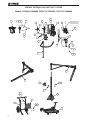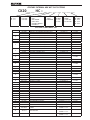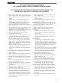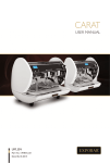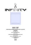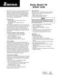
1
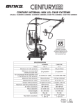
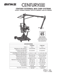
CENTURY EXTERNAL MIX WEt OUT SYSTEMS
Models: CX2006HC-J000000, CX2017HC-G000000, CX2017HC-J000000
CA PROP
65
PROP 65 WARNING
WARNING: This product
contains chemicals known to
the State of California to cause
cancer and birth defects or
other reproductive harm.
SPECIFICATIONS
CX2006HC
CX2017HC
6.5:1
17:1
Maximum air inlet pressure:
116 psi (8 bar)
116 psi (8 bar)
Maximum recommended
continuous cycle rate:
20 cycles/min
20 cycles/min
5.2 SCFM (147 LPM)
17.6 SCFM (498 LPM)
Maximum fluid pressure:
750 psi (52 bar)
1970 psi (136 bar)
Displacement per cycle:
4.3 oz (127 cc)
4.3 oz (127 cc)
Output @ 60 cycles/min:
2.0 gal/m (7.6 l/m)
2.0 gal/m (7.6 l/m)
Maximum operating temperature:
160°F (71°C)
160°F (71°C)
Air inlet connection:
3/8" NPT (F)
3/8" NPT (F)
Piston diameter:
3.3 in 85 mm)
5.5 in (140 mm)
Stroke length:
3 in (75 mm)
3 in (75 mm)
96.2 dB
97.3 dB
1 1/4" NPT (M) &
1" NPT (F)
1 1/4" NPT (M) &
1" NPT (F)
Ratio:
Air consumption @ 20 cycles/min and
116 psi (8 bar) air inlet pressure:
Sound level:
Fluid inlet connection:
Replaces
Part Sheet
77-2942
Part
Sheet
77-2942R
CENTURY EXTERNAL MIX WET OUT SYSTEMS
EXTERNAL MIX CENTURY WET OUT SYTEMS
Models: CX2006HC-J000000, CX2017HC-G000000, CX2017HC-J000000
9
1
2
3
4
5
8
10
8
5
11
BOOM REGULATOR &
TUBING INCLUDED
WITH ITEM 22 OR 28.
12
5
6
6
13
18
7
14
15
19
17
20
16
28
22
31
33
34
32
24
29
25
27
23
25
26
30
2
4
21
2
3
CENTURY EXTERNAL MIX WET OUT SYSTEMS
CX20__ __ HC – __ __ __ __ __ __ __
RATIO
06 6.5:1
17 17:1
GUN
G 102-2400
J 102-3600
0
1
2
3
4
MOUNTING
CATALYST
HEATER
WALL
WALL/BOOM
SMALL CART
CART/MAST/BOOM
CART/MAST
F FLOW
M MANIFOLD
0 NONE
1 110V
2 220V
SIPHON
0 NONE
S 5 GALLON
T 55 GALLON
HOSE
00
25
35
50
NONE
25 FT
35 FT
50 FT
SYSTEM COMPONENT LIST
Item No.
19
20
21
22
23
24
25
26
27
28
29
30
31
Part Number
102-2400
102-3600
71-7504
71-7502
71-8424
83-4233
102-3028
102-3029
102-3030
54-4989
71-4800
71-4801
54-4976
101-9469-100
101-9470
107-1646
237-908
CX2006HC
CX2017HC
103-1900
207-12305-9
207-11972
101-9435-K
103-1068
103-1093
207-12259-1
207-12351
207-12352
20-3340-1
20-3823-1
72-998
203-1610
41-28050
20-376-1
20-264-1
237-205
101-9445
203-1607
103-1602
103-1603
101-9475
32
207-10619
33
20-263-1
FLAT WASHER
34
20-6042
NYLOK HEX NUT
1
2
3
4
5
6
7
8
9
10
11
12
13
14
15
16
17
18
Description
CENTURY AA EXTERNAL MIX RESIN GUN
CENTURY LEL EXTERNAL MIX RESIN GUN
MATERIAL HOSE, 5/16" ID, 25 FT
MATERIAL HOSE, 5/16" ID, 10 FT
MATERIAL HOSE, 3/8" ID, 25 FT
DM NIPPLE
CATALYST HOSE ASSEMBLY, 25 FT
CATALYST HOSE ASSEMBLY, 35 FT
CATALYST HOSE ASSEMBLY, 50 FT
AIR HOSE ASSEMBLY, 25 FT
AIR HOSE ASSEMBLY, 35 FT
AIR HOSE ASSEMBLY, 50 FT
TUBE ADAPTER FITTING
LOW PRESSURE MANIFOLD ASSEMBLY
FLOW METER ASSEMBLY
MALE ELBOW
TUBE CONNECTOR
CX2006HC PUMP ASSEMBLY
CX2017HC PUMP ASSEMBLY
AIR CONTROL ASSEMBLY
CATALYST HOSE, 17"
CATATLST SIPHON/RETURN HOSE ASSEMBLY
CATALYST SUPPLY BOTTLE BRACKET KIT
55 GAL. SIPHON KIT ASSEMBLY
5 GAL. SIPHON KIT ASSEMBLY
FILTER ASSEMBLY (60 MESH)
HEATER KIT (120V)
HEATER KIT (220V)
STREET ELBOW
BUSHING
DM NIPPLE
WALL MOUNTED WET OUT BOOM ASSEMBLY
CART ASSEMBLY
HEX HEAD CAP SCREW
FLAT WASHER
NYLOK HEX NUT
CART ADAPTER BRACKET
WET OUT BOOM ASSEMBLY
AIR MANIFOLD ASSEMBLY
PORTA-CART ASSEMBLY
MAST MOUNTING BRACKET KIT
U-BOLT
QTY.
1 IF GUN = G
1 IF GUN = J
1 IF HOSE = 25 or 50
1 IF HOSE = 35
1 IF HOSE = 35 or 50
1 IF HOSE = 25, 35, 50
1 IF HOSE = 25
1 IF HOSE = 35
1 IF HOSE = 50
1 IF HOSE = 25
1 IF HOSE = 35
1 IF HOSE = 50
1
1 IF CATALYST = M
1 IF CATALYST = F
1
1
1 IF RATIO = 06
1 IF RATIO = 17
1
1
1
1
1 IF SIPHON = T
1 IF SIPHON = S
1
1 IF HEATER = 1
1 IF HEATER = 2
1 IF HOSE = 25, 35, 50
1 IF HOSE = 25, 35, 50
1 IF HOSE = 35 or 50
1 IF MOUNT = 1
1 IF MOUNT = 2
4 IF MOUNT = 2
8 IF MOUNT = 2
4 IF MOUNT = 2
1 IF MOUNT = 2
1 IF MOUNT = 3
1 IF MOUNT = 3 or 4
1 IF MOUNT = 3 or 4
1 IF MOUNT = 3 or 4
2 IF MOUNT = 3 or 4 &
HEATER = 1 or 2
4 IF MOUNT = 3 or 4 &
HEATER = 1 or 2
4 IF MOUNT = 3 or 4 &
HEATER = 1 or 2
Part Sheet
77-2520
77-2772
77-2945
77-2940
77-2944
77-2126
77-2807
77-2812
77-2311
77-2902
77-2311
77-2311
77-2311
3
CENTURY EXTERNAL MIX WET OUT SYSTEMS
WALL MOUNT DIMENSIONS
3"
76mm
29
28 32 "
735mm
6"
152mm
9
16 "
14mm
1
17 32 "
15
33 32 "
433mm
850mm
SMALL CART DIMENSIONS
13
48 32 "
1230mm
17
20 32 "
521mm
9
31 16 "
15
34 16 "
802mm
887mm
CART, MAST, AND BOOM DIMENSIONS
84"
2133mm
15
30 32 "
774mm
4
3
37 4 "
959mm
11
50 16 "
1287mm
WET-OUT SYSTEM START-UP PROCEDURES
FOR CX2006HC-J000000, CX2017HC-G000000 & CX2017HC-J000000
It is important to read through these instructions entirely and
understand them prior to operating the equipment.
1.Ensure all hose connections are tight, all valves are
in the “closed” position, and all regulators are backed
off to zero pressure. Attach ground wire to an earth
ground.
2.Attach a 1/2” or 3/8” air line, using main line air
pressure, to the inlet ball valve of the air control
assembly. Make sure the ball valve is in the closed
position. Air requirement is 20 CFM minimum.
3.Check catalyst and resin quantities. Ensure enough for
one shift of operation.
4.Have a sufficient amount (5 gal) of appropriate solvent
(acetone) for clean up and initial flush of pump.
5.Add throat lube to inside of packing nut at top of resin
pump. Stop when packing nut is half-full.
6.Disengage catalyst pump from the ratio arm by
removing the quick release pin.
7.Insert the catalyst pick up tube and screw cap into a
one-gallon catalyst container and tighten the cap.
8.With the air cap, front end o-rings, and nozzle (spray
tip) removed from the spray gun, move the trigger
lock to the down or “OFF” position, aim the gun into
an approved, grounded container and pull the trigger.
Touch the gun to the side of the container or connect
the gun to an earth ground.
9.Manually pump the catalyst pump to prime the pump,
manifold, hose, and gun. Do this until catalyst is
flowing freely from the end of the spray gun without
“spitting”.
10.Release the trigger of the spray gun, engage trigger
lock and wipe off any catalyst that may have collected
on the gun head.
11.Install the front head o-rings and night cap on the gun.
Secure the night cap with the retaining ring.
12.Rest the catalyst pump against the side of the bracket;
do NOT re-connect the pump to the ratio arm at this
time.
13.Insert the resin pump pick-up tube into a container of
acetone or other appropriate solvent.
14.Open the main air ball valve until fully open. During
this procedure air will leak from the ball valve bleed
hole, this is ok.
15.Release trigger lock and aim the gun into an approved,
grounded container, pull the trigger.
16.Slowly turn the pump regulator “T” handle clockwise
until the pump starts to run. This may take a bit of
adjusting by increasing and decreasing the pump air
pressure. The pump will run fast at first but as solvent
is pulled into the resin pump it will slow down. Keep
the pump running slowly until solvent is flowing
freely out of the gun.
17.Release the gun trigger and engage trigger lock then
wipe off head of gun.
18.Lift siphon tube out of solvent and let solvent bleed
back into container.
19.Close main air inlet ball valve. Back off pump air
regulator to zero pressure.
20.Open the relief or drain valve on the fluid filter and
drain completely, when finished, close the drain valve.
21.Insert the pick-up tube into container of resin.
22.Repeat steps 15 and 16.
23.Release the gun trigger and engage trigger lock.
24.Remove night cap and wipe off head of gun.
25.Install tip:
a. For LEL guns: Lube tip o-ring (20-5919) with
Devilbiss gun lube or Binks gunners mate. Install
tip on o-ring.
b. F
or AA guns: Hold gun vertically (nose up) and
place spray tip with installed tip seal on front of
head insert.
26.Install air cap:
a. For LEL guns: Place the 102-3609 air baffle into
the air cap. Place the air cap over the tip making
sure the flats and holes in the tip and air cap line up.
Screw the retaining ring onto the gun head and align
the tip and air cap to the desired position before
tightening the ring fully.
b. F
or AA guns: Place the air cap over the tip, aligning
the flats on each part. Screw the retaining ring onto
the gun head and align the tip and air cap to the
desired position before tightening the ring fully.
27.Operate the catalyst pump by hand to put
approximately 20 lbs of pressure on the catalyst
gauge. Re-connect the catalyst pump to the ratio arm
with the quick release pin.
28.Turn the “T” handle on the catalyst atomizing air
regulator until 20 lbs. is indicated on the air gauge.
29.With the spray gun aimed at an appropriate surface,
release the trigger lock, pull the trigger and have
someone turn the "T" handle clockwise, on the
"PUMP" regulator until the pressure is at 30 lbs.
30.The pressures of 20 lbs on the catalyst atomizing air
and 30 lbs of pump pressure are starting points and
will need to be adjusted for your individual situation.
When making adjustments always use 3 to 5 lb
increments at a time and check the results. When
properly adjusted, spray a sample surface and check
for gel time.
31.If the system has a fluid heater, set the thermostat to
90 to 100°F.
5
WET-OUT SYSTEM SHUT-DOWN PROCEDURES
Short-term shut down:
1.
IMPORTANT: always stop the pump in the
“down” position, to prevent resin from drying on
the pump rod and to keep it wet with throat lube.
2.Engage trigger lock on spray gun.
3.Turn off main air valve. The air will bleed out of the
pump and manifold.
4.Pull catalyst relief valve knob to bleed catalyst
pressure.
5.Open drain ball valve on filter to relieve resin
pressure.
6.Remove retaining ring, air cap and tip from the head
of the gun, keeping track of the o-rings, do not let
the red o-rings soak in acetone; they will swell. Wash
gun head in appropriate clean solvent. Lubricate
with gun lube or petroleum jelly and reinstall the
o-rings. Lubricate the threads on the head of the gun
and install the nightcap, reinstall retaining ring and
tighten.
7.Clean air cap, baffle and tip in clean solvent, dry and
store in clean dry place.
8.Clean gun with clean solvent. Oil all trigger parts,
needles and exposed threads.
9.Leave gun hanging with head facing in the down
position.
Longer term shut down:
1.Engage trigger lock on spray gun.
2.Shut main air valve. Air will bleed out of the pump
and manifold. Back off the pump regulator to zero
pressure. Back off atomizing air regulator to zero
pressure.
3.Pull catalyst relief valve knob to bleed catalyst
pressure.
4.Open drain ball valve on filter to relieve gel coat
pressure.
5.Make sure you have enough solvent (acetone) to
completely flush the resin pump, filter, hose, and gun.
6.Remove pin to disengage catalyst pump from ratio
arm.
7.Remove retaining ring, air cap, spray tip, and front
end gun o-rings. Wipe front end of gun clean.
8.Remove siphon from resin supply. Let drain into
supply and wipe clean.
9.Remove catalyst siphon from supply bottle. Trigger
gun into grounded waste container and pump catalyst
pump by hand to purge catalyst from pump, manifold,
hose, and gun. For further cleaning for longer term
storage, a soapy-water solution should be pumped
through the system to purge it of all catalyst. At this
time do not re-connect the catalyst pump to the ratio
arm. NEVER pump acetone through the catalyst
pump or allow acetone to mix with raw catalyst.
10.Again wipe front end of gun clean. Lubricate front
end o-rings and re-install, then install night cap and
retaining ring.
11.Trigger gun into grounded waste container.
6
12.Open main air supply valve. Increase pressure on
pump regulator until pump starts to run, drawing air
into the pump. Continue to run pump until air pushes
most of the resin from the system. Control the speed
of the pump by varying the air pressure to the motor.
13.Stop pump by backing off the air pressure. Release
gun trigger.
14.Place siphon pick-up tube in the container of solvent.
15.Trigger the gun into grounded waste container. Restart pump, drawing solvent into the pump and out
through the gun into the waste container. Occasionally
open drain ball valve to clean filter bowl with solvent.
16.Optional: When the solvent flowing from the gun
is reasonably clear, recirculate solvent through the
system by triggering the gun into the solvent supply, if
possible. Follow this flush sequence with clean solvent
for a final flush.
17.When solvent flowing from gun is clear, stop pump
and release gun trigger.
18.IMPORTANT: always stop the pump in the “down”
position, to keep the displacement rod wet with throat
lube or solvent.
19.Completely back off pump regulator to zero pressure.
Close main air valve. Open drain ball valve to relieve
pressure.
20.Solvent may be left in pump for shutdown period. For
longer term storage solvent should be replaced with a
mineral oil or other compatible fluid to keep seals and
metal parts lubricated and free from moisture.
NOTES
7
WARRANTY
This product is covered by Binks’ 1 Year Limited Warranty.
Binks Sales and Service: www.binks.com
U.S.A./Canada Customer Service
195 Internationale Blvd.
Glendale Heights, IL 60139
630-237-5000
Toll Free Customer Service
and Technical Support
800-992-4657
77-2942R Revisions: Trademark updates;
(P1) Added Prop 65 warning; (P8)
Updated contact information.
Toll Free Fax
888-246-5732
3/13 ©2013 Binks All rights reserved. Printed in U.S.A.