1
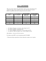
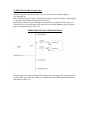
INSTALLATION AND
QUICK COMMISSIONING
INSTRUCTIONS
EWC WARM WATER TIME CLOCK
WATER SOFTENERS
ABSOLUTE MAXIMUM TEMPERATURE 60’C
Before commencing the installation, ensure that you read these
instructions thoroughly and you have all the necessary plumbing
fittings.
If you have any difficulties or need advice please telephone our
help line on:
01279 780250
HOW TO SET UP YOUR WATER SOFTENER
BEFORE FITTING
1. Please connect the brine pick up tube to the control valve - It is located at the rear
of the softener on the right hand side.
Push the tube firmly into the push fit fitting on the control valve - It is a good
idea to wet the end of the pipe to lubricate it a little. If you can pull it out again you
did not push it in firmly enough.
2. *Metered softener only* Please also fit the rear connection manifold, wet the ‘O’
rings, push the manifold firmly home and fit the two stainless steel locking clips using
the screws provided. Once manifold is fitted please connect the meter cable from the
back of the control valve to the hole in the top of the manifold.
*IMPORTANT*
Failure to use the locking clips or the screws WILL cause a flood when you
pressurise the softener.
3. For time clock softeners, please refer to page 2 of the service manual.
4. For metered softeners, please refer to pages 5 & 6 of the service manual.
5. Finally, fill the brine tank (cabinet) with salt to the top (you will need to refill the
brine tank with salt when it is half full)
Use salt tablets or pebbles only (block salt if you must and are feeling rich!)
As a general rule an “average” person uses approximately 160 liters of water per day,
this we refer to as “one person day”. So for example, if a water softener has a capacity
of 8 person days, this would mean:8 people for 1 day
4 people for 2 days
2 people for 4 days
1 person for 8 days
These figures would assume a water hardness of 20’ Clark (286 ppm) which is the
national average. This must only be considered as a guide line as the water hardness
varies greatly according to the area. If in doubt, contact your local water authority or
the European WaterCare service department on 01279 780250 for advice on water
hardness in your area.
E.W.C SOFTENERS
There are 5 water softener sizes in the E.W.C domestic range (many others in the
commercial range), all are available in either time clock or metered versions.
Below is a guideline table for the settings on your water softener.
MODEL
EWC
SALT SETTING
LB (PRESET)
CAPACITY ASSUMING
20’ CLARK HARDNESS.
PEOPLE DAYS
(TIME CLOCK)
CAPACITY ASSUMING
20’ CLARK HARDNESS.
US GALLONS
(METERED)*
5
2
4
150
10
3
8
300
14
5
12
500
18
7
16
600
23
8
20
800
25’ Clarke (358 ppm) is very hard - reduce figures by 25%
20’ Clarke (286 ppm) is moderately hard.
15’ Clarke (220 ppm) is mildly hard - increase figures by 25%
Less than 10’ Clarke (143 ppm) is soft - increase figures by 50%
Other hardness - increase or decrease pro-rata
If in doubt contact EWC service department on 01279 780250
* The metered figures quoted have already taken into account reserve capacity.
INSTALLATION INSTRUCTIONS
Water softeners are very easy to install - there are only four water connections:
1. Mains water inlet
2. Mains water outlet
3. Drain
4. Overflow
There is also an electrical connection that must be wired into a 240v AC mains power
supply.
(1) FITTINGS CHECK LIST
1. Inlet and outlet hoses
2. Drain hose
3. Overflow hose
4. Brine tank lid
5. Operation manual
(2) CHECK MAINS WATER PRESSURE
Maximum operating pressure 4 Bar
Minimum operation pressure 1.5 Bar
Optimum operation pressure 3 Bar
To find out your water pressure you can test with a gauge on an outside tap or a single
pillar tap. Alternatively you can contact your local water authority for your areas
mains water pressure.
If the pressure is too high in your area you may need to fit a pressure reducing valve.
This will prolong the life of the softener and reduce the risk of flooding due to over
pressurisation.
If the pressure is too low in your area you may need to fit a booster pump, this will
boost the mains water pressure up to the required pressure for the water softener to
work correctly. Please contact EWC for more details on 01279 780250.
(3) DRAIN RISING MAIN
Turn off the mains water supply at the stopcock and turn the kitchen cold tap on until
the water stops running.
(4) FIT BYPASS SET (If applicable)
Cut the rising main and fit the three valves as shown below to form a bypass
(see Diagram A)
Note: Install proprietary valves with direction of flow arrows as shown, terminating in
¾” bsp male (to accommodate the flexible hoses).
Garden taps and hard water drinking taps should be teed off prior to the bypass set.
You may have to run additional pipe work to alter existing plumbing, please contact
your local plumber if this is the case.
PIPEWORK INSTALLATION DIAGRAM
A non-return valve must be fitted in the rising main water pipe prior to the bypass set
or in the hard water inlet pipe. This is to comply with local Water Board Regulations
and must be adhered to.
(5) PLUMB IN THE SOFTENER INLET AND OUTLET HOSES
Using the hoses provided connect the softener inlet and outlet to the mains water pipe
work as shown to the previous diagram
Pressure drop
For all normal households with storage tanks, the standard hoses provided with the
water softener are adequate to supply all water requirements.
For all households with combination boilers etc connected directly to the mains water
supply, it is advised to plumb these systems directly into the water softener using
22mm copper pipe or wide bore hoses (Available from European WaterCare Ltd).
(6) PLUMB IN THE DRAIN
Fit the drain hose provided onto the ½” hose barb fitting on the control valve of the
water softener using the jubilee clip, then run the hose to a suitable drainage point i.e.
plastic stand pipe.
Please note: Care should be taken to position the hose so that:(a) It will not kink or fold
(b) It will not freeze
(c) The length of the drain hose is kept as short as possible
(d) It cannot move and become dislodged.
Please note: High water pressure may cause the hose to move during the backwash
section of the water softeners regeneration cycle. For this reason it is advised to fix
the hose to avoid this.
Please note: A suitable drain air gap should be provided to adhere to local Water
Authority Bye-Laws.
Please note: Keep the drain hose as short as possible.
(7) PLUMB IN THE OVERFLOW
It is most important that a satisfactory overflow system is provided. Connect a short
length of the yellow hose to the overflow elbow at the rear of the water softener. Run
this hose into wider piping - perhaps ¾” plastic pipe leading to the outside, making
sure that at no point does the hose or pipe run uphill, kink, or run higher than the
overflow outlet. The overflow must always run down hill.
Do not seal the join between the wider piping and the overflow to prevent an air lock
forming (see Diagram B).
DO NOT join the overflow hose to the drain hose - This WILL cause a flood during
the water softeners regeneration cycle.
OVERFLOW SETUP
(8) CONNECT THE ELECTRICITY SUPPLY
The water softener must be wired into a permanent electrical supply i.e. a fused spur
connection.
Maximum fuse 3 amp
Connection for wiring is as follows
Brown
Live
Blue
- Neutral
Yellow/Green
- Earth
WARNING: This appliance must be earthed. If in doubt consult a qualified
electrician.
LOFT OR UPPER FLOOR INSTALLATIONS
Extreme care should be taken with such installations, as the potential damage, should
there be a leak, could be extremely high.
The water softener must be installed inside a plastic water tank, this tank should then
be provided with a 1 ¼” overflow about half way up the side. This overflow must then
be run outside the building. The water softener overflow may then be ignored. The
drain however must still be installed and great care taken with all joints and protection
against freezing.
COMMISSIONING THE WATER SOFTENER
Please refer to the control valves manufactures manual for basic programming of the
timer, such as time and regeneration days etc.
CHECK INSTALLATION
Inlet to inlet pipe.
Outlet to outlet pipe
Drain and overflow as per instructions
Remember: Overflow water will not flow uphill.
Drain not kinked or in a position where it is possible to kink, freeze
or jump out of the drainage pipe due to water pressure.
Make sure that the water temperature is below 60’c.
Turn on the mains water supply.
Turn on the electricity supply.
Close bypass valve (if fitted).
Open inlet valve SLOWLY, you will hear a hissing noise as the water rushes
through the valve.
Once the hissing noise has stopped, open the outlet valve and run some water.
This may be a brown color at first, it is a stain washing out of the softener resin
and will do no harm. This will clear in approximately 2-3 minuets
Set timer or meter as described in the service manual.
The Water Softener is now on line and ready to use.
European WaterCare Ltd
Regal House
South Road
Harlow
Essex
CM20 2BL
Web:
E-mail:
Tel:
Fax:
WWW.Watercare.co.uk
[email protected]
01279 780250
01279 780268