1
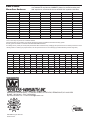
HONEYVILLE DISTRIBUTOR
ELECTRONIC POSITION CONTROL
SERVICE MANUAL
Model No.
EPC-GR3
Serial No.
Software Version
Honeyville Metal, Inc.
4200 S 900 W
Topeka, IN 46571
3.4
Phone (800) 593-8377
Fax (260) 593-2486
www.HoneyvilleMetal.com
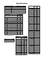
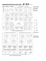
Specifications
General
Model No.
Serial No.
Software Version
Dealer Name
Order No.
Distributor Model No.
Distributor Serial No.
Factory
Setting
EPC-GR3
3.4
AC Drive Parameters
Factory
Setting
User
Setting
Motor Parameters
Motor Nameplate Voltage
Motor Nameplate Amps
Motor Base RPM
Ramp Parameters
P1.01
Acceleration Time 1
P1.02
Deceleration Time 1
Voltz/Hertz Parameters
P2.00
Volts/Hertz Settings
P2.01
Slip Compression
P2.10
Control Mode
Digital Parameters
P3.00
Source of Operation Command
P3.02
*Multi-Function Input DI3
P3.04
*Multi-Function Input DI5
Presets Parameters
P5.01
Multi-Speed 1
P5.02
Multi-Speed 2
P5.03
Multi-Speed 3
All Parameters not listed above are at default setting.
*P3.04 must be set before P3.02.
P0.00
P0.01
P0.03
PLC Settings
Factory
Setting
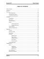
Power Requirements
220-240 VAC; 3 Phase; 60 Hz
440-480 VAC; 3 Phase; 60 Hz
Setup
Setup Password 555
Alignment Factor
Outlets
Spacing
Checkpoint
Precision
Resolution
Ratio
Medium Range
Slow Range
Green Range
Safety Timer
Remote Type
Calibration Type
Encoder Direction
Use Nicknames
User
Setting
Skip Outlets
Skip Outlet 1
0
Skip Outlet 2
0
Skip Outlet 3
0
Skip Outlet 4
0
Skip Outlet 5
0
Skip Outlet 6
0
Skip Outlet 7
0
Skip Outlet 8
0
Skip Outlet 9
0
Skip Outlet 10
0
Skip Outlet 11
0
Skip Outlet 12
0
Skip Outlet 13
0
Skip Outlet 14
0
Skip Outlet 15
0
Skip Outlet 16
0
Skip Outlet 17
0
Skip Outlet 18
0
Skip Outlet 19
0
Skip Outlet 20
0
Skip Outlet 21
0
Skip Outlet 22
0
Skip Outlet 23
0
Skip Outlet 24
0
Nicknames
Nickname 1
Nickname 2
Nickname 3
Nickname 4
Nickname 5
Nickname 6
Nickname 7
Nickname 8
Nickname 9
Nickname 10
Nickname 11
Nickname 12
Nickname 13
Nickname 14
Nickname 15
Nickname 16
Nickname 17
Nickname 18
Nickname 19
Nickname 20
Nickname 21
Nickname 22
Nickname 23
Nickname 24
User
Setting
Honeyville EPC
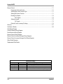
Table of Contents
TABLE OF CONTENTS
Table of Contents................................................................................................................................. 1-1
Introduction .......................................................................................................................................... 2-1
Parts List .............................................................................................................................................. 3-1
Drive Components .................................................................................................................. 3-2
Drive Electrical Enclosure ....................................................................................................... 3-4
Control Electrical Enclosure .................................................................................................... 3-6
Installation............................................................................................................................................ 4-1
Transportation......................................................................................................................... 4-1
Environment............................................................................................................................ 4-1
Disconnect Switch................................................................................................................... 4-1
Wiring...................................................................................................................................... 4-1
Connect the AC Lines ................................................................................................ 4-1
Connect the DC Lines ................................................................................................ 4-1
Test the Rotation..................................................................................................................... 4-2
Adjusting Calibration Arm........................................................................................................ 4-2
Operation ............................................................................................................................................. 5-1
Warning................................................................................................................................... 5-1
Direction of Travel................................................................................................................... 5-1
Status Lights ........................................................................................................................... 5-1
Functions ................................................................................................................................ 5-2
Manual Function ........................................................................................................ 5-2
Setup Function........................................................................................................... 5-3
Calibrate Function...................................................................................................... 5-7
Run Function.............................................................................................................. 5-7
Remote Function........................................................................................................ 5-8
PLC Message Lamp................................................................................................................ 5-8
Troubleshooting ................................................................................................................................... 6-1
Errors ...................................................................................................................................... 6-1
Invalid Entry ............................................................................................................... 6-1
Calibration Error......................................................................................................... 6-1
Motion Errors ............................................................................................................. 6-1
PLC Not Running .................................................................................................................... 6-2
Emergency Procedures........................................................................................................... 6-2
5/24/2012
1-1
Honeyville EPC
External Control................................................................................................................................... 7-1
Preparing for External Control ................................................................................................ 7-1
Selecting the Correct Remote Type........................................................................................ 7-1
Starting the Remote Function ................................................................................................. 7-1
Reading the Outputs............................................................................................................... 7-2
PLC Outputs.............................................................................................................. 7-2
Setting the Inputs.................................................................................................................... 7-3
PLC Inputs................................................................................................................. 7-3
External Control Accessory Package...................................................................................... 7-4
Warranty.............................................................................................................................................. 8-1
Certificate of Quality ............................................................................................................................ 8-2
Field Wiring Diagram
Control Enclosure Wiring Diagram
Drive Enclosure Wiring Diagram
External Control Wiring Diagram
External Control Accessory Package Wiring Diagrams
External Control Accessory Package Field Wiring Diagrams
Ziplink Cable Diagrams
Supplemental Data Sheets
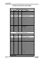
Publication History
Issue
First Edition
Second Edition
Third Edition
Fourth Edition
Fifth Edition
1-2
Date
8/12/2009
3/19/2010
5/2/2011
8/12/2011
5/24/2012
Description of Changes
Original Manual for EPC-GR3 with software version 3.0
Updated wiring diagrams for software version 3.1
Fixed statement and chart on 7-3
Added "Encoder Direction" setting
Version 3.4; Added External Control Accessory Package
5/24/2012
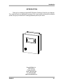
Introduction
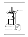
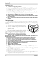
INTRODUCTION
Thank you for purchasing a Honeyville EPC (Electronic Positioning Control) for your distributor.
This manual will help you understand the operation of the control, guide you through the installation
process, and give you a reference for ordering replacement parts for your control.
Honeyville Metal, Inc.
4200 S 900 W
Topeka, IN 46571
Phone: (260) 593-2266
Fax: (260) 593-2486
www.HoneyvilleMetal.com
5/24/2012
2-1
Honeyville EPC
This page intentionally left blank.
2-2
5/24/2012
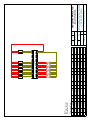
Parts List
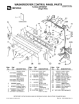
PARTS LIST
DRIVE
COMPONENTS……3-2
DRIVE
COMPONENTS
DRIVE ELECTRICAL
DRIVE
ELECTRICALENCLOSURE……3-4
ENCLOSURE
CONTROL ELECTRICAL
ELECTRICAL ENCLOSURE……3-6
CONTROL
ENCLOSURE
5/24/2012
3-1
Honeyville EPC
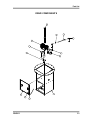
DRIVE COMPONENTS
Item
1
2
3
4
5
6
7
8
9
10
11
12
13
Part
DSSMxxxxxxxE †
DSHW1101
HWTR3007
HWNT0310
PTGR1221E
PTEM0997
DSHW1034A
HWRC0003
HWCH1003
Qty
1
1
1
1
1
2
1
4
1
1
1
2
1
Description
Ø 2 15/16 TGP Shaft
GR3 Drive Cabinet
Cabinet Door
GR3 Torque Arm Mount
GR3 Encoder Mount
5/8''-18 Female Rod End
5/8''-18 Threaded Rod x 10¾''
5/8''-18 Hex Nut
Winsmith 935MDSND 500:1 Gear Reducer
Black Max Y534 Motor 1/2 HP
Dynapar HS35R2000H37D Encoder
3/16'' U-Bolt
3/16" Chain x 19''
† Insert Distributor Model (ex. DSSM160645FE)
3-2
5/24/2012
Parts List
DRIVE COMPONENTS
1
7
8
6
9
10
11
4
5
2
3
12
13
5/24/2012
3-3
Honeyville EPC
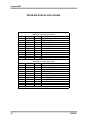
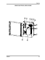
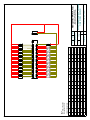
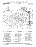
DRIVE ELECTRICAL ENCLOSURE
Item
1
2
3
4
5
6
7
8
9
10
11
DSECEE02H - High Voltage (440-480 VAC)
Part
Qty
Description
DSHW1042
1
Fiberglass Enclosure
DSHW1114
1*
RF022B43AA EMI Filter
DSHW1115
1
DURApulse GS3-41P0 AC Drive
DSHW1111
1
LR-41P0 460V AC Line Reactor
DSHW1112
2
RF220X00A RF Filter
DSHW1039
1
Enclosure Heater; 60 Watt; 60/40 T-Stat
DSHW1008
2
Terminal Block Ground
DSHW1011
17
Terminal Block Blue
DSHW1010
1
Terminal Block Gray
DSHW1032
1
2 Pole Jumper Bar
DSHW1006
2
End Bracket
Item
Part
1
DSHW1042
2
DSHW1121
3
DSHW1117
4
DSHW1120
5
DSHW1112
6
DSHW1039
7
DSHW1008
8
DSHW1011
9
DSHW1010
10
DSHW1032
11
DSHW1006
* Canada Only
3-4
DSECEE02L - Low Voltage (220-240 VAC)
Qty
Description
1
Fiberglass Enclosure
1*
10TDT1W4C EMI Filter
1
DURApulse GS3-21P0 AC Drive
1
LR-21P0 230V AC Line Reactor
2
RF220X00A RF Filter
1
Enclosure Heater; 60 Watt; 60/40 T-Stat
2
Terminal Block Ground
17
Terminal Block Blue
1
Terminal Block Gray
1
2 Pole Jumper Bar
2
End Bracket
5/24/2012
Parts List
DRIVE ELECTRICAL ENCLOSURE
5
4
7
10
9
8
11
2
1
6
5/24/2012
3
3-5
Honeyville EPC
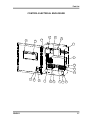
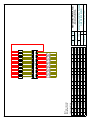
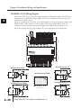
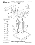
CONTROL ELECTRICAL ENCLOSURE
Item
1
2
3
4
5
6
7
8
9
10
11
12
13
14
15
16
17
18
19
20*
21
DSECCE02H - High Voltage (440-480 VAC)
Part
Qty
Description
DSHW1040
1
Fiberglass Enclosure
DSHW1110
1
GS-41P0-FKIT Fuse Kit
DSEC1002
1
240/480V to 120V Transformer
DSHW1116
1
LC1K0910F7 IEC Mini Contactor
DSHW1019
1
PS24-075D 24VDC Power Supply
DSHW1018
1
D0-06DD1-D Direct Logic PLC
DSHW1006
3
End Bracket
DSHW1010
14
Terminal Block Gray
DSHW1011
20
Terminal Block Blue
3
Terminal Block Ground
DSHW1008
DSHW1032
1
2 Pole Jumper Bar
DSHW1032
2
3 Pole Jumper Bar
DSHW1032
1
4 Pole Jumper Bar
DSHW1032
1
6 Pole Jumper Bar
DSHW1082
1
30MM Selector Switch
DSHW1081
1
30MM Contact Block
DSHW1080
1
30MM Nameplate Off/On
DSHW1022
1
EZ-220P EZText Operator Panel
DSHW1026
1
EZ-BRK-2 EZText Mounting Clips
DSHW1014
1
EZ-2CBL EZText Cable
1†
Enclosure Heater; 60 Watt; 60/40 T-Stat
DSHW1039
DSECCE02L - Low Voltage (220-240 VAC)
Item
Part
Qty
Description
1
DSHW1040
1
Fiberglass Enclosure
2
DSHW1118
1
GS-21P0-FKIT-3P Fuse Kit
3
DSEC1002
1
240/480V to 120V Transformer
4
DSHW1116
1
LC1K0910F7 IEC Mini Contactor
5
DSHW1019
1
PS24-075D 24VDC Power Supply
6
DSHW1018
1
D0-06DD1-D Direct Logic PLC
7
DSHW1006
3
End Bracket
8
DSHW1010
14
Terminal Block Gray
9
DSHW1011
20
Terminal Block Blue
3
Terminal Block Ground
10
DSHW1008
11
DSHW1032
1
2 Pole Jumper Bar
12
DSHW1032
2
3 Pole Jumper Bar
13
DSHW1032
1
4 Pole Jumper Bar
14
DSHW1032
1
6 Pole Jumper Bar
DSHW1082
1
30MM Selector Switch
15
16
DSHW1081
1
30MM Contact Block
17
DSHW1080
1
30MM Nameplate Off/On
DSHW1022
1
EZ-220P EZText Operator Panel
18
DSHW1026
1
EZ-BRK-2 EZText Mounting Clips
19
20*
DSHW1014
1
EZ-2CBL EZText Cable
1†
Enclosure Heater; 60 Watt; 60/40 T-Stat
21
DSHW1039
* Hidden † Optional
3-6
5/24/2012
Parts List
CONTROL ELECTRICAL ENCLOSURE
3
18
21
19
4
5
1
6
8
9
10
17
5/24/2012
15
16
2
11 12
7 13 14
3-7
Honeyville EPC
This page intentionally left blank.
3-8
5/24/2012
Installation
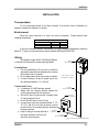
INSTALLATION
Transportation
Do not put excessive stress on the drive enclosure. If the electric control is attached to a
distributor, transport the distributor on its back.
Environment
Mount the control enclosure in a clean, dry, indoor environment. Please observe these
operating temperatures:
Operating Temperatures
Minimum Maximum
Control Enclosure
40° F
120° F
Drive Enclosure
-40° F
185° F
If the control enclosure needs to be mounted in a location where the temperature could drop
below 40° F, there is an optional enclosure heater available (HMI item # DSHW1039).
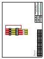
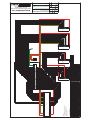
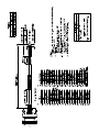
Wiring
See diagram at right and the “Field Wiring Diagram”
in the back of this manual for conduit and wiring details.
Incoming Power
It is the responsibility of the end user to install the
appropriate power disconnect between the incoming
power supply and the controller.
Do not apply power until all other wiring is complete.
Connect incoming 3 phase AC power lines to the
blue terminals labeled L1, L2, L3 and G.
DRIVE
ENCLOSURE
RUN AC AND DC LINES
IN SEPARATE CONDUITS
Connect the AC Lines
DC LINES
6 conductors of 14 AWG wire are required.
(12) 18 GA WIRES*
Always take the shortest distance between the
control enclosure and the drive enclosure.
CONTROL
Run the AC wire in its own conduit. If possible, keep
ENCLOSURE
12” away from the DC lines.
Do not allow DC lines to cross AC lines
Connect wires to the blue terminals labeled T1, T2,
T3, G, 51 and 52 in the control enclosure; connect
the other end to the corresponding blue terminals in
the drive enclosure.
INCOMING
Keep AC wiring to the lower left side of 3-PHASE AC
the control enclosure, and to the left
AC LINES
(6) 14 GA WIRES*
side of the drive enclosure.
*DO NOT EXCEED RECOMMEND WIRE SIZES
5/24/2012
4-1
Honeyville EPC
Connect the DC Lines
12 conductors of 18 AWG wire are required.
For best results, use Belden 9556 or equivalent 18 AWG 6 twisted pair shielded control cable.
Always take the shortest distance between the control enclosure and the drive enclosure.
Run the DC cable in its own conduit. If possible, keep 12” away from AC lines.
Do not allow DC lines to cross AC lines
Connect wires to the blue terminals labeled 1 to 12 in the control enclosure; connect the other
end to the corresponding blue terminals in the drive enclosure.
Use a twisted pair for connections 1 & 2, 3 & 4, 5 & 6, 7 & 8, 9 & 10 and 11 & 12.
Connect the shield to ground in the control enclosure only. Do not connect the shield to ground
in the drive enclosure.
Keep DC wiring to the lower right side of the control enclosure, and to the right side of the drive
enclosure.
Test the Rotation
When the wiring is complete, you must test the rotation of the motor. Press the “Manual” button
on the Operator Panel to enter the Manual Mode. While pressing the “Up” arrow on the keypad, verify
the following:
3 SE
R
VE
RE
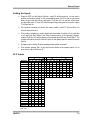
Adjust the Reference Point on the Encoder
8
7
2
If the spout is rotating in the opposite direction, switch the
T1 and T3 wires in the control enclosure and repeat steps 1 and 2.
1
1. The number showing on the display should be increasing.
2. The spout should be rotating counter-clockwise when
viewed from the top.
6
4
5
D
AR
RW
O
F
TOP VIEW
The reference point on the encoder has been preset at
the factory. Under normal circumstances you should not need to make any changes to the
reference point on the encoder.
If the encoder has been removed, please follow this procedure for setting the reference point:
1. Use manual mode to turn the spout to outlet 1, which is the outlet to the left of the door.
2. Continue to use manual mode to align then left side of the spout with the left side of outlet 1.
3. In the drive enclosure, remove the encoder.
4. Rotate the collar to align the mark on the top collar of the encoder with the center of the cord.
5. Align the slot in the bracket with the hole on the encoder mount.
6. Slide the encoder onto the shaft
7. Tighten the collar on the top of the encoder.
8. With the power on in the control enclosure, check the X2 light on the PLC. If it is lit, continue to
step 10.
9. Loosen the bolt on the anchor tab on the encoder, and rotate the encoder slightly until the X2
light on the PLC is lit. Tighten the bolt.
10. Repeat steps 7 and 8 until the X2 light on the PLC is lit.
11. Replace the cover on the bottom of the encoder.
12. You will need to calibrate, and then adjust the alignment factor. See “Alignment Factor” in the
“Setup Function” section of the “Operation” chapter.
4-2
5/24/2012
Operation
OPERATION
Direction of Travel
8
1
7
2
3 SE
R
VE
RE
In this documentation, forward means the spout is
moving up to a higher outlet number, toward the last outlet,
or counterclockwise when looking at the Distributor from
above. On a Flatback Honeyville Distributor, forward is
moving away from the door.
Reverse means the spout is moving down to a
lower outlet number, toward the first outlet, or clockwise
when looking at the Distributor from above. On a Flatback
Honeyville Distributor, reverse is moving toward the door.
6
4
5
D
AR
RW
O
F
TOP VIEW
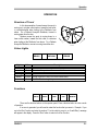
Status Lights
READY
MOVING
Light
Color
Ready
Green
Red
Moving
Yellow Spout is in motion.
Error
ERROR
Description
Spout is in position. Distributor is ready to be used.
Spout is not in position. Do not use distributor.
Yellow Action required. Follow on-screen instructions.
Red See "Troubleshooting" chapter.
Functions
MANUAL
SETUP
CALIB
RUN
REMOTE
There are five function buttons on the operator panel. Press a function button to enter a mode
of operation.
If an error is generated, you will need to restart the function that you were in. Example: If you
are in the Run Function and enter the number “0” as the outlet to move to, an “Invalid Entry” message
will appear in the display. Press the “Run” button to return to the Run Function.
5/24/2012
5-1
Honeyville EPC
Manual Function
Enter the Manual Function by pressing the “Manual” button on the Operator Panel.
The Manual Function is primarily for diagnostic and maintenance purposes.
The number displayed is the distance from the zero reference point.
Use caution when using the Manual Function; it is possible to run the spout into the back
wall of a Flatback Distributor.
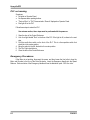
Process
1. Press the Up arrow on the Operator Panel to move the spout forward.
2. Press the Down arrow to move the spout in reverse.
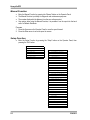
Setup Function
Enter the Setup Function by pressing the “Setup” button on the Operator Panel, then
pressing the "Esc" button.
Honeyville EPC
Version 3.4
+Settings
+Skip Outlets
+Nicknames
+Status
Save Settings?
5-2
-Settings
Alignment Factor?
Outlets?
Spacing?
Checkpoint?
Precision?
Resolution?
Ratio?
Medium Range?
Slow Range?
Green Range?
Safety Timer?
Remote Type?
Calibration Type?
Encoder Direction?
Use Nicknames?
-Skip Outlets
Skip Outlet 1?
Skip Outlet 2?
...
Skip Outlet 24?
-Nicknames
Nickname 1?
Nickname 2?
...
Nickname 24?
-Status
Encoder:
Current Pos:
Target Pos:
Calib Low:
Calib High:
Green Low:
Green High:
5/24/2012
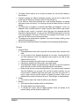
Operation
The Setup Function needs to be run at least once before you can start the Calibrate or
Run Functions.
Changes to settings are effective immediately; however, they will not be retained if the
power is shut off unless you change the value of "Save Settings" to 1.
If your Electronic Control was purchased with a new Honeyville Distributor, the settings
have been pre-set at the factory. You should go through the Setup Function to verify the
settings.
The Setup menu is arranged in a hierarchy with folders and messages. A plus (+) is
displayed in front of a folder's name if it is closed. Press the "Enter" button to open a folder.
If a folder is open, a minus (-) is placed in front of the name. Any messages within that
folder will be displayed below it. You may use the UP/DOWN arrow buttons to scroll down
to the next message in that folder. At the end of the messages for that folder, you can
press the "Esc" button to move to the previous level.
The settings can be viewed without a password. If you need to change a setting, you are
required to enter a password.
See enclosed "Specifications Sheet" for the password and the settings described below.
Process
1. Alignment Factor
These adjustments ensure that the spout will lock into position when centered on the
outlet.
You only need to set the alignment adjustments for one outlet. Assuming that all of
your other settings are correct, if the alignment is set correctly for one outlet, all other
outlets will also be correct.
If the spout is stopping to the right of center, use a smaller number.
If the spout is stopping to the left of center, use a larger number.
These adjustment numbers are obtained through a trial and error process in which the
spout is moved to an outlet, and then visually inspected for centeredness.
During the trail and error process described above, if you have previously completed
Setup and Calibration, you can press “Run” and not be forced to calibrate. You can
move the outlet to a different outlet, (then back again if you wish), then press "Esc" to
return to setup and enter another number and repeat the process. When you are
satisfied with the position of the spout, be sure to "Save Settings" as described below.
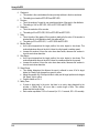
2. Outlets
This number is equal to the number of outlets on your distributor.
3. Spacing
This number is distance between outlets on the distributor.
The number based on the precision setting.
To calculate this number, take the degrees between outlets and multiply by the
precision setting, and then divide the result by 360.
5/24/2012
5-3
Honeyville EPC
4. Checkpoint
This number is the count between the two proximity switches in the drive enclosure.
This setting is not used on EPC-GR2 and EPC-GR3.
5. Precision
This is the number of counts for one complete revolution of the spout in the distributor.
This setting is 1440 on EPC-GR1; 2000 on EPC-GR2 and EPC-GR3.
6. Resolution
This is the resolution of the encoder.
This setting is 60 on EPC-GR1; 2000 on EPC-GR2 and EPC-GR3.
7. Ratio
This is the ratio of the gearbox if the encoder is attached to the motor. If the encoder is
attached directly to the distributor shaft, this setting will be 1.
This setting is 500 on EPC-GR1; 1 on EPC-GR2 and EPC-GR3
8. Medium Range
As the spout approaches the target position, the motor begins to slow down. This
number determines the point at which it slows from high speed to medium speed.
Increase this number to have the motor slow down earlier; decrease this number to
have the motor slow down later.
9. Slow Range
As the spout approaches the target position, the motor begins to slow down. This
number determines the point at which it slows from medium speed to slow speed.
Increase this number to have the motor slow down earlier; decrease this number to
have the motor slow down later.
10. Green Range
This number determines the distance the spout is allowed to move off of its target
before the “Ready” light changes from green to yellow.
Adjust this number only if the spout tends to coast past its target position and changes
the “Ready” light to yellow.
Possible values are 0 to 3.
11. Safety Timer
If power is being sent to the motor, but there is no motion being detected by the
encoder, a “Motion Error” will occur after a certain length of time. This number
determines that length of time.
Each number represents 1/100th of a second (i.e. 50 = .5 seconds; 200 = 2.0 seconds)
5-4
5/24/2012
Operation
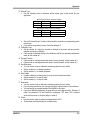
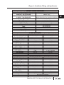
12. Remote Type
Use the following chart to determine which remote type is best suited for your
application
Without External Control Accessory Package
Setting
Description
Numb er of Outlets
4 to 24
0
Binary
1
Direct
4 to 8
With External Control Accessory Package *
Setting
Description
Numb er of Outlets
4 to 24
0
Binary
1
Direct
4 to 24
* See page 7-4 for details
See the “External Control” chapter in this manual for information on implementing each
remote type
If you are not using external control, leave this setting at 0.
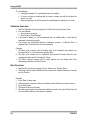
Calibration Type
Set this number to 0 when the encoder is attached to the motor and two proximity
switches are used for calibration.
If the encoder is attached directly to the distributor shaft and no proximity switches are
used, set this number to 1.
Encoder Direction
If the encoder is counting up when the spout is moving forward, set this number to 0.
If the encoder is counting up when the spout is moving forward, set this number to 1.
Use Nicknames
You can choose to use an alternative numbering system for your outlets.
Set this number to 0 to disable nicknames.
Set this number to 1 to enable nicknames.
Skip Outlets
If certain outlets are not being used, you can choose to skip those outlets.
Set this number to 0 to use an outlet.
Set this number to 1 to skip an outlet
Nicknames
You can choose to use an alternative numbering system for your outlets.
If you are using nicknames, you may enter either the original number or the nickname.
You may assign any number between 25 and 9999 to any outlet.
If you have duplicate nicknames, the spout will stop at the highest outlet. Example: If
outlet 2 is nicknamed "100" and if outlet 5 is nicknamed "100", when "100" is entered
as the outlet to move to, the spout will go to outlet 5.
Status
Lists the current values for several variables within the PLC.
These values are used primarily for troubleshooting.
13.
14.
15.
16.
17.
18.
5/24/2012
5-5
Honeyville EPC
19. Save Settings
Change this number to 1 to permanently save your settings.
If you do not save your settings after you make a change, they will be lost when the
power is shut off.
After saving settings, you will be required to calibrate before continuing in run mode.
Calibrate Function
Enter the Calibrate Function by pressing the “Calib” button on the Operator Panel.
You must calibrate:
1. Every time you power up
2. Every time you "Save Settings"
If the power is always on, it is recommended that you calibrate daily to verify that the
equipment is functioning properly.
If any errors are encountered during the Calibration process, a “Calibration Error” is
displayed. See "Troubleshooting" for more information.
Process
1. The Motor runs in reverse until the leading edge of the Calibration Arm passes over
Proximity Switch A. This sets the zero reference point.
2. The Motor runs forward until the Calibration Arm reaches Proximity Switch B, then
compares it position with the "Checkpoint" setting.
3. The Motor continues forward until the spout reaches the last usable outlet, then
automatically switches to the Run Function.
Run Function
Enter the Run Function by pressing the “Run” button on the Operator Panel.
The Setup Function and the Calibrate Function need to be completed before you can start
the Run Function.
Process
1. Press "Enter" to begin input.
2. Use the keypad to enter the number (or nickname) of the outlet that you want to move to.
3. Press “Enter” again.
4. The spout will move to that outlet.
5. When the spout reaches the outlet and is locked into position, the green "Ready" light will
turn on and the Distributor will be ready for operation.
5-6
5/24/2012
Operation
Remote Function
Enter the Remote Function by pressing the "Remote" button on the Operator Panel.
The Setup Function and the Calibrate Function need to be completed before you can start
the Remote Function.
While in the Remote Function, the bottom line of the display will read "Remote".
When the green light is on, the top line shows the current outlet and the Distributor is ready
for operation.
See the "External Control" chapter for more information.
PLC Message Lamp
5/24/2012
There are two types of messages on the operator panel: Setup Messages and PLC
Messages.
If the PLC Message lamp is off, you are in the Setup Messages.
You can alternate between the two types of messages by pressing the "Esc" button.
It is possible to enter the Setup Messages without pressing the "Setup" button. However, it
is advisable to press the "Setup" button before entering "Setup" to clear any functions that
are running.
The panel locks out all key presses for 3 seconds after a PLC Message is displayed in
order to ensure the operator has a chance to read the message.
5-7
Honeyville EPC
This page intentionally left blank.
5-8
5/24/2012
Troubleshooting
TROUBLESHOOTING
Errors
Invalid Entry
Cause:
Entering a number on the keypad that is too high or too low
Action:
Press the Function button to restart the Function that you were performing.
Calibration Error
Occurs when an error is encountered during the Calibration process.
Causes:
Calibration Errors
Loose or incorrect wiring
Number
Description
Faulty Encoder, Speed Reducer,
1
Arm stays over switch A.
Motor, Starter, or PLC.
2
Switch B is on when arm is at switch A.
Actions:
3
Switch B turns on too soon.
4
Arm
is past switch B.
Check that all wiring is connected
5
No
usable
outlets.
properly.
Enter the Manual Function and press an arrow button. If the displayed number changes,
the Motor and Encoder are working. If the spout moves, the Motor and Speed Reducer
are working.
Stay in the Manual Function and open the Control Enclosure. If you press the “Down”
button, the “Y1” light on the PLC should light up, and the reverse side of the Starter should
click in. If you press the “Up” button, the “Y0” light on the PLC should light up, and the
forward side of the Starter should click in.
Motion Error
Occurs when power is being sent to the Motor, but the Encoder isn’t registering
motion.
Causes:
Debris or ice in Distributor
Loose or faulty wiring.
Faulty Encoder, Motor, Starter, or PLC.
Actions:
Run the Calibration Function. The cause of the error might be cleared.
Open the inspection door on the Distributor check for obstructions.
Check that all wiring is connected properly.
5/24/2012
6-1
Honeyville EPC
PLC not running
Symptoms:
No lights on Operator Panel.
No response when pushing buttons.
"Protocol Error" or "PLC Communication Timeout" displayed on Operator Panel.
Run light off on the PLC.
Follow these steps to restart the PLC.
Use extreme caution; these steps must be performed with the power on.
1. Open the door of the Control Enclosure.
2. Look for a light labeled "Run" on the face of the PLC. If the light is off, continue to the next
step.
3. Find the small silver switch on the front of the PLC. This is a three-position switch that
should be in the center position.
4. Move the switch to the left, the back to the center position.
5. The "Run" light should be on.
6. Close the door of the Control Enclosure.
Emergency Procedures
If the Motor is not working, disconnect the power, and then loosen the four bolts to drop the
Motor and Encoder to the floor of the Drive Enclosure. Insert the Emergency Handle into the Speed
Reducer. Each revolution of the Emergency Handle will turn the distributor spout 1/300 of a circle.
6-2
5/24/2012
External Control
EXTERNAL CONTROL
Preparing for External Control
1. Your EPC can be controlled from an external system by using the inputs and outputs on
the PLC as described in this chapter.
2. The inputs are 12-24 VDC sinking or sourcing.
3. The outputs are 12-24 VDC sinking.
4. You can use power from the 24 VDC power supply in the Control Enclosure.
5. See the "External Control Wiring Diagram" for additional information.
6. An optional External Control Accessory Package is available to assist you in connecting
and controlling your EPC from an external system. See page 7-4 for details.
Selecting the Correct Remote Type
1. Use the following chart to determine which remote type is best suited for your application:
Without External Control Accessory Package
Setting
Description
Number of Outlets
0
Binary
4 to 24
1
Direct
4 to 8
With External Control Accessory Package *
Setting
Description
Number of Outlets
0
Binary
4 to 24
1
Direct
4 to 24
* See page 7-4 for details
2. The remote type needs to be set using the setup function. See the Setup Function of the
Operations chapter of this manual for more details.
Starting the Remote Function
1. Every time you power up the EPC, you must calibrate before entering the Remote
Function.
2. Enter the Remote Function by pressing the "Remote" button on the Operator Panel.
3. The Run Function and the Remote Function operate exclusively of each other. You cannot
operate them both at the same time.
5/24/2012
7-1
Honeyville EPC
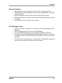
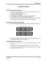
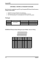
Reading the Outputs
When the EPC is in the Remote Function, output Y6 will be turned on. This indicates that it
is ready to accept a command from the inputs.
When the spout is in position and the Ready light is green, output Y7 will be turned on. The
corresponding value of the current outlet will be turned on in outputs Y10-Y14. This
happens whether the EPC is in Remote Function or not.
PLC Outputs
C1
Description
Remote
Ready
Current: 1
Current: 2
Current: 3
Current: 4
Current: 5
Current: 6
Current: 7
Current: 8
Current: 9
Current: 10
Current: 11
Current: 12
Current: 13
Current: 14
Current: 15
Current: 16
Current: 17
Current: 18
Current: 19
Current: 20
Current: 21
Current: 22
Current: 23
Current: 24
Y6
1
Y7
1
Binary (Remote Type 0)
C2
C3
Y10 Y11 Y12 Y13 Y14
1
0
1
0
1
0
1
0
1
0
1
0
1
0
1
0
1
0
1
0
1
0
1
0
0
1
1
0
0
1
1
0
0
1
1
0
0
1
1
0
0
1
1
0
0
1
1
0
0
0
0
1
1
1
1
0
0
0
0
1
1
1
1
0
0
0
0
1
1
1
1
0
0
0
0
0
0
0
0
1
1
1
1
1
1
1
1
0
0
0
0
0
0
0
0
1
0
0
0
0
0
0
0
0
0
0
0
0
0
0
0
1
1
1
1
1
1
1
1
1
Direct (Remote Type 1)
C2
C3
Y10 Y11 Y12 Y13 Y14 Y15 Y16 Y17
1
0
0
0
0
0
0
0
0
1
0
0
0
0
0
0
0
0
1
0
0
0
0
0
0
0
0
1
0
0
0
0
0
0
0
0
1
0
0
0
0
0
0
0
0
1
0
0
0
0
0
0
0
0
1
0
0
0
0
0
0
0
0
1
0=Off, 1=On
7-2
5/24/2012
External Control
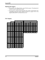
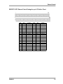
Setting the Inputs
When the EPC is in the Remote Function, output Y6 will be turned on. You can send a
position command by turning on the corresponding inputs X10-X14. After a one second
delay, the spout will start turning, and output Y7 will turn off. You can turn off the inputs
any time after output Y7 turns off. When the spout stops turning and is in position, output
Y7 will turn back on.
If the position command you send is the current position, output Y7 will turn off for one
second, then turn back on.
If the position command you send is higher then the number of outlets, or is an outlet that
is not used (see Skip Outlets in the Setup Function section of the Operation Chapter),
outputs Y6 will turn off, and the display on the operator panel will read "Invalid Entry". The
operator will need to press the "Remote" button on the operator panel to restart the remote
function.
All inputs must be turned off before sending another position command.
If the operator presses "Run" or any other function button on the operator panel, or if an
error occurs, output Y6 will turn off.
PLC Inputs
Binary (Remote Type 0)
C2
C3
Description X10 X11 X12 X13 X14
Move to: 1
1
0
0
0
0
Move to: 2
0
1
0
0
0
Move to: 3
1
1
0
0
0
Move to: 4
0
0
1
0
0
Move to: 5
1
0
1
0
0
Move to: 6
0
1
1
0
0
Move to: 7
1
1
1
0
0
Move to: 8
0
0
0
1
0
Move to: 9
1
0
0
1
0
Move to: 10
0
1
0
1
0
Move to: 11
1
1
0
1
0
Move to: 12
0
0
1
1
0
Move to: 13
1
0
1
1
0
Move to: 14
0
1
1
1
0
Move to: 15
1
1
1
1
0
Move to: 16
0
0
0
0
1
Move to: 17
1
0
0
0
1
Move to: 18
0
1
0
0
1
Move to: 19
1
1
0
0
1
Move to: 20
0
0
1
0
1
Move to: 21
1
0
1
0
1
Move to: 22
0
1
1
0
1
Move to: 23
1
1
1
0
1
Move to: 24
0
0
0
1
1
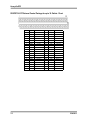
Direct (Remote Type 1)
C2
X10 X11
1
0
0
1
0
0
0
0
0
0
0
0
0
0
0
0
C3
X12 X13 X14 X15
0
0
0
0
0
0
0
0
1
0
0
0
0
1
0
0
0
0
1
0
0
0
0
1
0
0
0
0
0
0
0
0
X16 X17
0
0
0
0
0
0
0
0
0
0
0
0
1
0
0
1
0=Off, 1=On
5/24/2012
7-3
Honeyville EPC
EXTERNAL CONTROL ACCESSORY PACKAGE
Note: this section is applicable to your EPC only if the optional EPC External Control Accessory
Package has been installed.
Simplifies the wiring for all External Control Applications.
Allows you to use “direct” remote control type on distributors of any size.
See “Field Wiring Diagram” for each package later in this manual for wiring details.
Packages
Item Number
DSECEP08
DSECEP12
DSECEP18
DSECEP24
Binary (Remote Type 0)
Direct (Remote Type 1)
Up to 8 outlets
Up to 12 outlets
Up to 18 outlets
Up to 24 outlets
Up to 24 outlets
Compatibility
Version 2.2 and higher
Version 3.4 and higher
Version 3.4 and higher
Version 3.4 and higher
DSECEP08: EPC External Control Package for up to 8 Outlets - Direct, All - Binary
7-4
Term
Type
Function
Term
Type
Function
1
Output
Current: 1
11
Input
Move to: 1
2
Output
Current: 2
12
Input
Move to: 2
3
Output
Current: 3
13
Input
Move to: 3
4
Output
Current: 4
14
Input
Move to: 4
5
Output
Current: 5
15
Input
Move to: 5
6
Output
Current: 6
16
Input
Move to: 6
7
Output
Current: 7
17
Input
Move to: 7
8
Output
Current: 8
18
Input
Move to: 8
9
Output
Remote Mode
19
Power
24V DC -
10
Output
Ready
20
Power
24V DC +
5/24/2012
External Control
DSECEP12: EPC External Control Package for up to 12 Outlets - Direct
Term
Type
Function
Term
Type
Function
1
Output
Current: 1
21
Input
Move to: 1
2
Output
Current: 2
22
Input
Move to: 2
3
Output
Current: 3
23
Input
Move to: 3
4
Output
Current: 4
24
Input
Move to: 4
5
Output
Current: 5
25
Input
Move to: 5
6
Output
Current: 6
26
Input
Move to: 6
7
Output
Current: 7
27
Input
Move to: 7
8
Output
Current: 8
28
Input
Move to: 8
9
Output
Current: 9
29
Input
Move to: 9
10
Output
Current: 10
30
Input
Move to: 10
11
Output
Current: 11
31
Input
Move to: 11
12
Output
Current: 12
32
Input
Move to: 12
13
33
14
34
15
35
16
36
17
37
18
5/24/2012
38
19
Output
Remote Mode
39
Power
24V DC -
20
Output
Ready
40
Power
24V DC +
7-5
Honeyville EPC
DSECEP18: EPC External Control Package for up to 18 Outlets - Direct
7-6
Term
Type
Function
Term
Type
Function
1
Output
Current: 1
21
Input
Move to: 1
2
Output
Current: 2
22
Input
Move to: 2
3
Output
Current: 3
23
Input
Move to: 3
4
Output
Current: 4
24
Input
Move to: 4
5
Output
Current: 5
25
Input
Move to: 5
6
Output
Current: 6
26
Input
Move to: 6
7
Output
Current: 7
27
Input
Move to: 7
8
Output
Current: 8
28
Input
Move to: 8
9
Output
Current: 9
29
Input
Move to: 9
10
Output
Current: 10
30
Input
Move to: 10
11
Output
Current: 11
31
Input
Move to: 11
12
Output
Current: 12
32
Input
Move to: 12
13
Output
Current: 13
33
Input
Move to: 13
14
Output
Current: 14
34
Input
Move to: 14
15
Output
Current: 15
35
Input
Move to: 15
16
Output
Current: 16
36
Input
Move to: 16
17
Output
Current: 17
37
Input
Move to: 17
18
Output
Current: 18
38
Input
Move to: 18
19
Output
Remote Mode
39
Power
24V DC -
20
Output
Ready
40
Power
24V DC +
5/24/2012
External Control
DSECEP24: EPC External Control Package for up to 24 Outlets - Direct
5/24/2012
Term
Type
Function
Term
Type
Function
1
Output
Current: 1
26
Input
Move to: 1
2
Output
Current: 2
27
Input
Move to: 2
3
Output
Current: 3
28
Input
Move to: 3
4
Output
Current: 4
29
Input
Move to: 4
5
Output
Current: 5
30
Input
Move to: 5
6
Output
Current: 6
31
Input
Move to: 6
7
Output
Current: 7
32
Input
Move to: 7
8
Output
Current: 8
33
Input
Move to: 8
9
Output
Current: 9
34
Input
Move to: 9
10
Output
Current: 10
35
Input
Move to: 10
11
Output
Current: 11
36
Input
Move to: 11
12
Output
Current: 12
37
Input
Move to: 12
13
Output
Current: 13
38
Input
Move to: 13
14
Output
Current: 14
39
Input
Move to: 14
15
Output
Current: 15
40
Input
Move to: 15
16
Output
Current: 16
41
Input
Move to: 16
17
Output
Current: 17
42
Input
Move to: 17
18
Output
Current: 18
43
Input
Move to: 18
19
Output
Current: 19
44
Input
Move to: 19
20
Output
Current: 20
45
Input
Move to: 20
21
Output
Current: 21
46
Input
Move to: 21
22
Output
Current: 22
47
Input
Move to: 22
23
Output
Current: 23
48
Input
Move to: 23
24
Output
Current: 24
49
Input
Move to: 24
25
Output
Remote Mode
50
Output
Ready
7-7
Honeyville EPC
This page intentionally left blank.
7-8
5/24/2012
Warranty
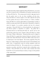
WARRANTY
The full extent of the warranty supplied by Honeyville Metal, Inc. is to correct
any defects in material and/or workmanship on the products manufactured only
by Honeyville Metal, Inc. This warranty period extends for one year from the
date the product arrives on the site where installation will take place.
Honeyville Metal, Inc. retains the right to review and/or adjust the time period
for those products that may be held in inventory at a dealer's warehouse.
Honeyville Metal, Inc. retains the final authority on determining if a product is
within the warranty period and if full replacement of that product is required to
retain the integrity of our products reputation and meet the customer's
expectations. Honeyville Metal, Inc. will not furnish labor for replacement of
any defective product or components of a product.
Any product that is
determined defective by both Honeyville Metal, Inc. and the end user who
purchased the product may not be returned to Honeyville Metal, Inc. without
the receipt of Return Authorization. Returned products must be shipped to
Honeyville Metal, Inc. prepaid unless instructed otherwise and must be clearly
marked with a Return Merchandise Authorization (RMA) number that needs to
be obtained prior to the return shipment. This warranty supplied by Honeyville
Metal, Inc. excludes damage to products while in transit to the destination on all
public forms of transportation except the trucking equipment owned and
operated by Honeyville Metal, Inc. This warranty does not cover performance
guarantees on products, only defects in material and/or workmanship as prior
statement. Honeyville Metal, Inc. does honor vendor warranties that extend
beyond the one year period and will pass warranty coverage on to the purchaser
of that vendor product.
5/24/2012
8-1
Honeyville EPC
CERTIFICATE OF QUALITY
Every effort has been made to make this equipment the best value you can
obtain for your money.
All the components have been inspected and
assembled. The complete system has been tested to insure proper operation.
We sincerely hope this equipment and our efforts meet with your approval. The
full extent of Honeyville Metal, Inc. warranty is to correct any defects in
material or workmanship in those products manufactured by Honeyville Metal,
Inc. Motors and drives, and all electrical and air control parts carry a one-year
warranty.
READ INSTRUCTIONS CAREFULLY BEFORE OPERATING!
THIS UNIT WAS FINAL INSPECTED AND PACKED BY ________________
8-2
5/24/2012
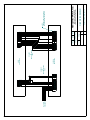
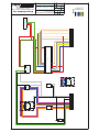
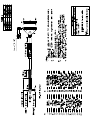
INCOMING
3-PHASE AC
L1 L2 L3 G T1 T2 T3 G
T1 T2 T3 51 52 G
51 52
AC LINES
TO
DRIVE ENCLOSURE
14 GA
CONTROL
ENCLOSURE
DC LINES
TO
DRIVE ENCLOSURE
18 GA
DRIVE
ENCLOSURE
7
MARK
DRAWING #:
SCALE:
1 of 1
SHEET:
---
Sheet1
SHEET NAME:
REV:
A
SIZE:
10 Field Wiring Diagram-GR23.dft
FILE NAME:
9 10 11 12 G
DRAWN BY: CHKED BY:
8
7 8 9 10 11 12
5/10/2012 CURT
DATE:
1 2 3 4 5 6
G 1 2 3 4 5 6
GROUP 2 & 3 DISTRIBUTOR EPC
FIELD WIRING DIAGRAM
4200 S. 900 W. • TOPEKA, INDIANA 46571
PHONE (260) 593-2266 • FAX (260) 593-2486
Honeyville Metal, Inc.
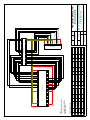
NOTE:
CONNECT SHIELD TO GROUND
IN CONTROL ENCLOSURE ONLY
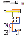
OFFON
4
3
OFF/ON
SWITCH
TR120
H2
X1
H4
L1 L2 L3 G T1 T2 T3 G
L1 L2 L3
FUSE
KIT
H3
T1 T2 T3
X2
H1
440-480 VAC INPUT
TRANSFORMER
120 VAC OUTPUT
HIGH VOLTAGE OPTION
FUSE
ACIO
51 52
CON
T1 T2 T3
L1 L2 L3
+
X2
H1
H3
H2
X1
H4
220-240 VAC INPUT
TRANSFORMER
120 VAC OUTPUT
LOW VOLTAGE OPTION
-
HEATER
A2
A1
CONTACTOR
HEAT
TR120
PLC
PS24
D0-06 PLC
C0 Y0 Y1 Y2 Y3 C1 Y4 Y5 Y6 Y7 C2 Y10 Y11 Y12 Y13 C3 Y14 Y15 Y16 Y17 +V
C0 X0 X1 X2 X3 C1 X4 X5 X6 X7 C2 X10 X11 X12 X13 C3 X14 X15 X16 X17 C4 X20 X21 X22 X23
+ G -
+ -
24V DC
POWER SUPPLY
L N G
DCIO
1 2 3 4 5 6
7
8
9 10 11 12 G
OP
+ - G
BLACK
WHITE
ORANGE
BLUE
PURPLE
GREEN
YELLOW
GRAY
BROWN
LEGEND
DRAWN BY: CHKED BY:
CURT MARK
CEE Wiring-GR23.dft
SHEET NAME:
SIZE:
B
REV:
THIS DRAWING AND ALL INFORMATION CONTAINED HEREIN IS THE PROPERTY
OF HONEYVILLE METAL, INC., AND IS NOT TO BE REPRODUCED WITHOUT THE
EXPRESS WRITTEN PERMISSION OF HMI.
ALL DIMENSIONS MUST BE FIELD VERIFIED BY THE CONTRACTOR. HMI SHALL
NOT BE RESPONSIBLE FOR ANY DIMENSIONAL DISCREPENCIES WHICH HAVE
NOT BEEN BROUGHT TO THEIR ATTENTION PRIOR TO CONSTRUCTION.
CONTROL ELECTRICAL ENCLOSURE
WIRING DIAGRAM
OPERATOR PANEL
DATE:
3/17/2010
FILE NAME:
SHEET:
Sheet1
1 of 1
SCALE:
---
DRAWING #:
Honeyville Metal, Inc.
MATERIAL HANDLING EQUIPMENT AND DUST CONTROL SYSTEMS
4200 S. 900 W. • TOPEKA, INDIANA 46571
PHONE (260) 593-2266 • FAX (260) 593-2486
HMI
GROUP 2 & 3 DISTRIBUTOR EPC - VERSION 3.1
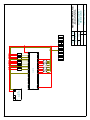
HEAT
+
-
T1 T2 T3 51 52 G
A1 A2 B1 B2 C1 C2
AC LINE
REACTOR
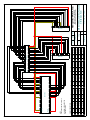
NOTE:
LOOP EACH WIRE THREE TIMES
(FOUR TURNS) THROUGH RF FILTERS.
AC MOTOR
P1 P2 T1 T2 T3 T4 T7 T5 T8 T6 T9
HEATER
MHI
HIGH VOLTAGE OPTION
ACLR
ACIO
RF FILTER
RF FILTER
MLO
P1 P2 T1 T7 T2 T8 T3 T9 T4 T5 T6
AC MOTOR
LOW VOLTAGE OPTION
EMI
L1 L2 L3
EMI
FILTER
L1 L2 L3
ACD
L1 L2 L3
AC
DRIVE
DI4 DI3 D12 DI1
T1 T2 T3
DCM
DCIO
ENC
G 1 2 3 4 5 6
G A A B B Z Z COM +V
7 8 9 10 11 12
BLACK
WHITE
ORANGE
BLUE
PURPLE
GREEN
YELLOW
GRAY
BROWN
LEGEND
DRAWN BY: CHKED BY:
CURT MARK
THIS DRAWING AND ALL INFORMATION CONTAINED HEREIN IS THE PROPERTY
OF HONEYVILLE METAL, INC., AND IS NOT TO BE REPRODUCED WITHOUT THE
EXPRESS WRITTEN PERMISSION OF HMI.
ALL DIMENSIONS MUST BE FIELD VERIFIED BY THE CONTRACTOR. HMI SHALL
NOT BE RESPONSIBLE FOR ANY DIMENSIONAL DISCREPENCIES WHICH HAVE
NOT BEEN BROUGHT TO THEIR ATTENTION PRIOR TO CONSTRUCTION.
DEE Wiring-GR23.dft
SHEET NAME:
SIZE:
B
REV:
ENCODER
GREEN
BROWN
BROWN/WHITE
ORANGE
ORANGE/WHITE
YELLOW/WHITE
YELLOW
BLACK
RED
DATE:
3/18/2010
FILE NAME:
SHEET:
DRIVE ELECTRICAL ENCLOSURE
WIRING DIAGRAM
Sheet1
1 of 1
SCALE:
---
DRAWING #:
Honeyville Metal, Inc.
MATERIAL HANDLING EQUIPMENT AND DUST CONTROL SYSTEMS
4200 S. 900 W. • TOPEKA, INDIANA 46571
PHONE (260) 593-2266 • FAX (260) 593-2486
HMI
GROUP 2 & 3 DISTRIBUTOR EPC - VERSION 3.1
PS24
24V DC
POWER SUPPLY
+ -
PLC
L N G
+ G -
L L L L
D0-06 PLC
C0 Y0 Y1 Y2 Y3 C1 Y4 Y5 Y6 Y7 C2 Y10 Y11 Y12 Y13 C3 Y14 Y15 Y16 Y17 +V
L L L L
1 2 3 4 5 6
C0 X0 X1 X2 X3 C1 X4 X5 X6 X7 C2 X10 X11 X12 X13 C3 X14 X15 X16 X17 C4 X20 X21 X22 X23
INPUT
OUTPUT
L L
DCIO
7
8
DRAWING #:
SCALE:
1 of 1
SHEET:
---
Sheet1
SHEET NAME:
EC Wiring-GR23.dft
FILE NAME:
REV:
A
SIZE:
MARK
DRAWN BY: CHKED BY:
5/30/2012 CURT
DATE:
9 10 11 12 G
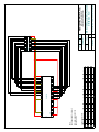
GROUP 2 &3 DISTRIBUTOR EPC
EXTERNAL CONTROL
WIRING DIAGRAM
4200 S. 900 W. • TOPEKA, INDIANA 46571
PHONE (260) 593-2266 • FAX (260) 593-2486
Honeyville Metal, Inc.
D0-06 PLC
C0 Y0 Y1 Y2 Y3 C1 Y4 Y5 Y6 Y7 C2 Y10 Y11 Y12 Y13 C3 Y14 Y15 Y16 Y17 +V
ZIPLINK CONNECTIONS
Term Type
Function
1 Output Current: 1
2 Output Current: 2
3 Output Current: 3
4 Output Current: 4
5 Output Current: 5
Term
6
7
8
9
10
NO WIRING IS REQUIRED FOR
UNUSED OUTLETS.
Type
Function
Output Current: 6
Output Current: 7
Output Current: 8
Output Remote Mode
Output
Ready
Term
11
12
13
14
15
Type
Input
Input
Input
Input
Input
Function
Move to: 1
Move to: 2
Move to: 3
Move to: 4
Move to: 5
Term
16
17
18
19
20
Type
Input
Input
Input
Power
Power
C0 X0 X1 X2 X3 C1 X4 X5 X6 X7 C2 X10 X11 X12 X13 C3 X14 X15 X16 X17 C4 X20 X21 X22 X23
INPUT
OUTPUT
NOTE:
USE ZIPLINK CABLE ZL-CBL24-1P
PLC
+ G -
Function
Move to: 6
Move to: 7
Move to: 8
24V DC 24V DC +
ZIPLINK
DSECEP08
---
Sheet1
SHEET NAME:
08 Wiring.dft
DRAWING #:
SCALE:
1 of 1
SHEET:
FILE NAME:
REV:
A
SIZE:
MARK
DRAWN BY: CHKED BY:
5/18/2012 CURT
DATE:
11 12 13 14 15 16 17 18 19 20
INPUT
ZL-RTB20
1 2 3 4 5 6 7 8 9 10
OUTPUT
UP TO 8 OUTLETS - DIRECT; ALL OUTLETS - BINARY
EPC EXTERNAL CONTROL PACKAGE
WIRING DIAGRAM
4200 S. 900 W. • TOPEKA, INDIANA 46571
PHONE (260) 593-2266 • FAX (260) 593-2486
Honeyville Metal, Inc.
ZIPLINK CONNECTIONS
Term Type
Function
1 Output Current: 1
2 Output Current: 2
3 Output Current: 3
4 Output Current: 4
5 Output Current: 5
NOTE:
NO WIRING IS REQUIRED
FOR UNUSED OUTLETS.
Term
6
7
8
9
10
Type
Function
Output Current: 6
Output Current: 7
Output Current: 8
Output Remote Mode
Output
Ready
Term
11
12
13
14
15
Type
Input
Input
Input
Input
Input
Function
Move to: 1
Move to: 2
Move to: 3
Move to: 4
Move to: 5
Term
16
17
18
19
20
ZIPLINK
ZL-RTB20
Type
Input
Input
Input
Power
Power
Function
Move to: 6
Move to: 7
Move to: 8
24V DC 24V DC +
11 12 13 14 15 16 17 18 19 20
INPUT
OUTPUT
1 2 3 4 5 6 7 8 9 10
L L L L L L L L L L
---
Sheet1
SHEET NAME:
DSECEP08
DRAWING #:
SCALE:
1 of 1
SHEET:
08 Field Wiring.dft
FILE NAME:
REV:
A
SIZE:
MARK
DRAWN BY: CHKED BY:
5/18/2012 CURT
DATE:
UP TO 8 OUTLETS - DIRECT; ALL OUTLETS - BINARY
EPC EXTERNAL CONTROL PACKAGE
FIELD WIRING DIAGRAM
4200 S. 900 W. • TOPEKA, INDIANA 46571
PHONE (260) 593-2266 • FAX (260) 593-2486
Honeyville Metal, Inc.
D0-06 PLC
ZIPLINK CONNECTIONS
Term Type
Function
1 Output Current: 1
2 Output Current: 2
3 Output Current: 3
4 Output Current: 4
5 Output Current: 5
6 Output Current: 6
7 Output Current: 7
8 Output Current: 8
Term
9
10
11
12
13
14
15
16
NO WIRING IS REQUIRED FOR
UNUSED OUTLETS.
NOTE:
USE ZIPLINK CABLE ZL-CBL40-1P
Type
Output
Output
Output
Output
Function Term Type
Function
Current: 9
17
Current: 10 18
Current: 11 19 Output Remote Mode
Current: 12 20 Output
Ready
21 Input
Move to: 1
22 Input
Move to: 2
23 Input
Move to: 3
24 Input
Move to: 4
Term
25
26
27
28
29
30
31
32
Type
Input
Input
Input
Input
Input
Input
Input
Input
C0 Y0 Y1 Y2 Y3 C1 Y4 Y5 Y6 Y7 C2 Y10 Y11 Y12 Y13 C3 Y14 Y15 Y16 Y17 +V
C0 X0 X1 X2 X3 C1 X4 X5 X6 X7 C2 X10 X11 X12 X13 C3 X14 X15 X16 X17 C4 X20 X21 X22 X23
INPUT
OUTPUT
+ G -
ZL-RTB40
I/O MODULE
24V DC 24V DC +
Function
DSECEP12
---
Sheet1
SHEET NAME:
12 Wiring.dft
DRAWING #:
SCALE:
1 of 1
SHEET:
FILE NAME:
REV:
A
SIZE:
MARK
DRAWN BY: CHKED BY:
5/18/2012 CURT
DATE:
C0
C0
0
1
2
3
C1
C1
0
1
2
3
+V
21 22 23 24 25 26 27 28 29 30 31 32 33 34 35 36 37 38 39 40
INPUT
Function Term Type
Move to: 5
33
Move to: 6
34
Move to: 7
35
Move to: 8
36
Move to: 9
37
Move to: 10 38
Move to: 11 39 Power
Move to: 12 40 Power
ZIPLINK
1 2 3 4 5 6 7 8 9 10 11 12 13 14 15 16 17 18 19 20
INPUT
OUTPUT
PLC
OUTPUT
D0-08CDD1
UP TO 12 OUTLETS - DIRECT
EPC EXTERNAL CONTROL PACKAGE
WIRING DIAGRAM
4200 S. 900 W. • TOPEKA, INDIANA 46571
PHONE (260) 593-2266 • FAX (260) 593-2486
Honeyville Metal, Inc.
ZIPLINK CONNECTIONS
Term Type
Function
1 Output Current: 1
2 Output Current: 2
3 Output Current: 3
4 Output Current: 4
5 Output Current: 5
6 Output Current: 6
7 Output Current: 7
8 Output Current: 8
NOTE:
NO WIRING IS REQUIRED
FOR UNUSED OUTLETS.
Term
9
10
11
12
13
14
15
16
Type
Output
Output
Output
Output
L L
ZL-RTB40
Term
25
26
27
28
29
30
31
32
Type
Input
Input
Input
Input
Input
Input
Input
Input
Function Term Type
Move to: 5
33
Move to: 6
34
Move to: 7
35
Move to: 8
36
Move to: 9
37
Move to: 10 38
Move to: 11 39 Power
Move to: 12 40 Power
24V DC 24V DC +
Function
21 22 23 24 25 26 27 28 29 30 31 32 33 34 35 36 37 38 39 40
INPUT
OUTPUT
1 2 3 4 5 6 7 8 9 10 11 12 13 14 15 16 17 18 19 20
L L L L L L L L L L L L
Function Term Type
Function
Current: 9
17
Current: 10 18
Current: 11 19 Output Remote Mode
Current: 12 20 Output
Ready
21 Input
Move to: 1
22 Input
Move to: 2
23 Input
Move to: 3
24 Input
Move to: 4
ZIPLINK
---
Sheet1
SHEET NAME:
DSECEP12
DRAWING #:
SCALE:
1 of 1
SHEET:
12 Field Wiring.dft
FILE NAME:
REV:
A
SIZE:
MARK
DRAWN BY: CHKED BY:
5/18/2012 CURT
DATE:
UP TO 12 OUTLETS - DIRECT
EPC EXTERNAL CONTROL PACKAGE
FIELD WIRING DIAGRAM
4200 S. 900 W. • TOPEKA, INDIANA 46571
PHONE (260) 593-2266 • FAX (260) 593-2486
Honeyville Metal, Inc.
D0-06 PLC
C0 Y0 Y1 Y2 Y3 C1 Y4 Y5 Y6 Y7 C2 Y10 Y11 Y12 Y13 C3 Y14 Y15 Y16 Y17 +V
ZIPLINK CONNECTIONS
Term Type
Function
1 Output Current: 1
2 Output Current: 2
3 Output Current: 3
4 Output Current: 4
5 Output Current: 5
6 Output Current: 6
7 Output Current: 7
8 Output Current: 8
Term
9
10
11
12
13
14
15
16
NO WIRING IS REQUIRED FOR
UNUSED OUTLETS.
Type
Output
Output
Output
Output
Output
Output
Output
Output
Function Term Type
Function
Current: 9
17 Output Current: 17
Current: 10 18 Output Current: 18
Current: 11 19 Output Remote Mode
Current: 12 20 Output
Ready
Current: 13 21 Input
Move to: 1
Current: 14 22 Input
Move to: 2
Current: 15 23 Input
Move to: 3
Current: 16 24 Input
Move to: 4
C0 X0 X1 X2 X3 C1 X4 X5 X6 X7 C2 X10 X11 X12 X13 C3 X14 X15 X16 X17 C4 X20 X21 X22 X23
INPUT
OUTPUT
+ G -
NOTE:
USE ZIPLINK CABLE ZL-CBL40-1P
PLC
ZL-RTB40
Type
Input
Input
Input
Input
Input
Input
Input
Input
D0-10ND3
INPUT
I/O MODULE
Function Term Type
Move to: 5
33 Input
Move to: 6
34 Input
Move to: 7
35 Input
Move to: 8
36 Input
Move to: 9
37 Input
Move to: 10 38 Input
Move to: 11 39 Power
Move to: 12 40 Power
Function
Move to: 13
Move to: 14
Move to: 15
Move to: 16
Move to: 17
Move to: 18
24V DC 24V DC +
DATE:
5
C1
4
3
2
1
0
C0
11
DSECEP18
---
Sheet1
SHEET NAME:
18 Wiring.dft
DRAWING #:
SCALE:
1 of 1
SHEET:
FILE NAME:
REV:
A
SIZE:
UP TO 18 OUTLETS - DIRECT
EPC EXTERNAL CONTROL PACKAGE
WIRING DIAGRAM
4200 S. 900 W. • TOPEKA, INDIANA 46571
PHONE (260) 593-2266 • FAX (260) 593-2486
Honeyville Metal, Inc.
10
MARK
11
+V
7
5/14/2012 CURT
7
10
6
DRAWN BY: CHKED BY:
I/O MODULE
6
OUTPUT
5
C1
NC
4
3
2
1
0
C0
21 22 23 24 25 26 27 28 29 30 31 32 33 34 35 36 37 38 39 40
INPUT
Term
25
26
27
28
29
30
31
32
ZIPLINK
1 2 3 4 5 6 7 8 9 10 11 12 13 14 15 16 17 18 19 20
OUTPUT
D0-10TD1
ZIPLINK CONNECTIONS
Term Type
Function
1 Output Current: 1
2 Output Current: 2
3 Output Current: 3
4 Output Current: 4
5 Output Current: 5
6 Output Current: 6
7 Output Current: 7
8 Output Current: 8
NOTE:
NO WIRING IS REQUIRED
FOR UNUSED OUTLETS.
Term
9
10
11
12
13
14
15
16
Type
Output
Output
Output
Output
Output
Output
Output
Output
ZL-RTB40
Term
25
26
27
28
29
30
31
32
Type
Input
Input
Input
Input
Input
Input
Input
Input
Function Term Type
Move to: 5
33 Input
Move to: 6
34 Input
Move to: 7
35 Input
Move to: 8
36 Input
Move to: 9
37 Input
Move to: 10 38 Input
Move to: 11 39 Power
Move to: 12 40 Power
Function
Move to: 13
Move to: 14
Move to: 15
Move to: 16
Move to: 17
Move to: 18
24V DC 24V DC +
21 22 23 24 25 26 27 28 29 30 31 32 33 34 35 36 37 38 39 40
INPUT
OUTPUT
1 2 3 4 5 6 7 8 9 10 11 12 13 14 15 16 17 18 19 20
L L L L L L L L L L L L L L L L L L L L
Function Term Type
Function
Current: 9
17 Output Current: 17
Current: 10 18 Output Current: 18
Current: 11 19 Output Remote Mode
Current: 12 20 Output
Ready
Current: 13 21 Input
Move to: 1
Current: 14 22 Input
Move to: 2
Current: 15 23 Input
Move to: 3
Current: 16 24 Input
Move to: 4
ZIPLINK
---
Sheet1
SHEET NAME:
DSECEP18
DRAWING #:
SCALE:
1 of 1
SHEET:
18 Field Wiring.dft
FILE NAME:
REV:
A
SIZE:
MARK
DRAWN BY: CHKED BY:
5/18/2012 CURT
DATE:
UP TO 18 OUTLETS - DIRECT
EPC EXTERNAL CONTROL PACKAGE
FIELD WIRING DIAGRAM
4200 S. 900 W. • TOPEKA, INDIANA 46571
PHONE (260) 593-2266 • FAX (260) 593-2486
Honeyville Metal, Inc.
'3/&
& < < < < & < < < < & < < < < & < < < < 9
=,3/,1.&211(&7,216
7HUP 7\SH
)XQFWLRQ
2XWSXW &XUUHQW
2XWSXW &XUUHQW
2XWSXW &XUUHQW
2XWSXW &XUUHQW
2XWSXW &XUUHQW
2XWSXW &XUUHQW
2XWSXW &XUUHQW
2XWSXW &XUUHQW
7HUP
12:,5,1*,65(48,5(')25
8186('287/(76
7\SH
2XWSXW
2XWSXW
2XWSXW
2XWSXW
2XWSXW
2XWSXW
2XWSXW
2XWSXW
)XQFWLRQ 7HUP 7\SH
&XUUHQW
2XWSXW
&XUUHQW 2XWSXW
&XUUHQW 2XWSXW
&XUUHQW 2XWSXW
&XUUHQW 2XWSXW
&XUUHQW 2XWSXW
&XUUHQW 2XWSXW
&XUUHQW 2XWSXW
,1387
7\SH
,QSXW
,QSXW
,QSXW
,QSXW
,QSXW
,QSXW
,QSXW
,QSXW
'1'
)XQFWLRQ 7HUP 7\SH
0RYHWR
,QSXW
0RYHWR
,QSXW
0RYHWR ,QSXW
0RYHWR ,QSXW
0RYHWR ,QSXW
0RYHWR ,QSXW
0RYHWR ,QSXW
0RYHWR ,QSXW
)XQFWLRQ 7HUP 7\SH
0RYHWR ,QSXW
0RYHWR 2XWSXW
0RYHWR
0RYHWR
0RYHWR
0RYHWR
0RYHWR
0RYHWR
,202'8/(
)XQFWLRQ
0RYHWR
5HDG\
9
&
&
,1387
'1'
,202'8/(
&
1&
&
9 9
9 9
287387
6* 6*
'7'
&
1&
&
,202'8/(
=,3/,1.
)XQFWLRQ 7HUP 7\SH
)XQFWLRQ 7HUP
&XUUHQW 2XWSXW 5HPRWH0RGH &XUUHQW ,QSXW
0RYHWR
&XUUHQW ,QSXW
0RYHWR
&XUUHQW ,QSXW
0RYHWR
&XUUHQW ,QSXW
0RYHWR
&XUUHQW ,QSXW
0RYHWR
&XUUHQW ,QSXW
0RYHWR
&XUUHQW ,QSXW
0RYHWR
& ; ; ; ; & ; ; ; ; & ; ; ; ; & ; ; ; ; & ; ; ; ;
,1387
287387
* 127(
86(=,3/,1.&$%/(=/&%/3
3/&
=/57%
9
&
&
DRAWN BY: CHKED BY:
DATE:
THIS DRAWING AND ALL INFORMATION CONTAINED HEREIN IS THE PROPERTY
OF HONEYVILLE METAL, INC., AND IS NOT TO BE REPRODUCED WITHOUT THE
EXPRESS WRITTEN PERMISSION OF HMI.
'7'
287387
,202'8/(
+RQH\YLOOH0HWDO,QF
:LULQJGIW
&857 0$5.
0$7(5,$/+$1'/,1*(48,30(17$1''867&21752/6<67(06
ALL DIMENSIONS MUST BE FIELD VERIFIED BY THE CONTRACTOR. HMI SHALL
NOT BE RESPONSIBLE FOR ANY DIMENSIONAL DISCREPENCIES WHICH HAVE
NOT BEEN BROUGHT TO THEIR ATTENTION PRIOR TO CONSTRUCTION.
FILE NAME:
,1387
SCALE:
287387
'6(&(3
6:723(.$,1',$1$
3+21()$;
SHEET NAME:
SHEET:
SIZE:
(3&(;7(51$/&21752/3$&.$*(
:,5,1*',$*5$0
6KHHW
RI
%
8372287/(76',5(&7
+0,
REV:
DRAWING #:
ZIPLINK CONNECTIONS
Term Type
Function Term Type
1 Output Current: 1
11 Output
2 Output Current: 2
12 Output
3 Output Current: 3
13 Output
4 Output Current: 4
14 Output
5 Output Current: 5
15 Output
6 Output Current: 6
16 Output
7 Output Current: 7
17 Output
8 Output Current: 8
18 Output
9 Output Current: 9
19 Output
10 Output Current: 10 20 Output
NOTE:
NO WIRING IS REQUIRED
FOR UNUSED OUTLETS.
ZL-RTB50
Term
31
32
33
34
35
36
37
38
39
40
Type
Input
Input
Input
Input
Input
Input
Input
Input
Input
Input
Function Term Type
Move to: 6
41 Input
Move to: 7
42 Input
Move to: 8
43 Input
Move to: 9
44 Input
Move to: 10 45 Input
Move to: 11 46 Input
Move to: 12 47 Input
Move to: 13 48 Input
Move to: 14 49 Input
Move to: 15 50 Output
Function
Move to: 16
Move to: 17
Move to: 18
Move to: 19
Move to: 20
Move to: 21
Move to: 22
Move to: 23
Move to: 24
Ready
SG SG
---
Sheet1
SHEET NAME:
DSECEP24
DRAWING #:
SCALE:
1 of 1
SHEET:
REV:
A
SIZE:
MARK
24 Field Wiring.dft
FILE NAME:
V- V+
V- V+
DRAWN BY: CHKED BY:
5/18/2012 CURT
DATE:
L
26 27 28 29 30 31 32 33 34 35 36 37 38 39 40 41 42 43 44 45 46 47 48 49 50
INPUT
OUTPUT
1 2 3 4 5 6 7 8 9 10 11 12 13 14 15 16 17 18 19 20 21 22 23 24 25
L L L L L L L L L L L L L L L L L L L L L L L L L
Function Term Type
Function
Current: 11 21 Output Current: 21
Current: 12 22 Output Current: 22
Current: 13 23 Output Current: 23
Current: 14 24 Output Current: 24
Current: 15 25 Output Remote Mode
Current: 16 26 Input
Move to: 1
Current: 17 27 Input
Move to: 2
Current: 18 28 Input
Move to: 3
Current: 19 29 Input
Move to: 4
Current: 20 30 Input
Move to: 5
ZIPLINK
UP TO 24 OUTLETS - DIRECT
EPC EXTERNAL CONTROL PACKAGE
FIELD WIRING DIAGRAM
4200 S. 900 W. • TOPEKA, INDIANA 46571
PHONE (260) 593-2266 • FAX (260) 593-2486
Honeyville Metal, Inc.
Chapter 2: Installation, Wiring, and Specifications
D0–06DD1–D I/O Wiring Diagram
1
2
3
4
5
6
7
8
9
10
11
12
13
14
A
B
C
D
These micro PLCs feature twenty DC inputs and sixteen sinking DC outputs. The following
diagram shows a typical field wiring example. The DC external power connection uses four
terminals at the left as shown.
Inputs are organized into five banks of four. Each bank has an isolated common terminal, and
may be wired as either sinking or sourcing inputs. The wiring example below shows all
commons connected together, but separate supplies and common circuits may be used.
All outputs actually share the same common. Note the requirement for external power.
12 - 24 VDC
-
+
+24 VDC
L L L L
G
LG
+
-
OUTPUT: Sinking Output
Y
X
0
1
2
3
INPUT: 12 - 24V
L L L L
L L L L
+
L L L L
N.C. Y0
Y2
C1
Y5
Y7 Y10 Y12
C3 Y15 Y17
N.C. C0
Y1
Y3
Y4
Y6
C2
Y11 Y13 Y14 Y16 +V
6 - 27V
4
5
1.0A
6
7
PWR: 12-24
10
11
12
13
20W
14
15
16
17
20
D0-06DD1-D
21 22
23
3 - 15mA
LOGIC
C0
06
K oyo
X1
X0
X3
X2
X4
C1
X6
X5
X7
C2 X11 X13 X14 X16 C4 X21 X23 N.C.
X10 X12 C3
X15 X17 X20 X22 N.C.
DC
Supply
DC Pulse Outputs (Y0 - Y1)
High Speed Inputs (X0-X3)
Input
+
Internal module circuitry +V
+V
+V
+
Optical
Isolator
Derating Chart for DC Outputs
To LED
L
–
Optical
Isolator
+
Points
Common
OUTPUT
To LED
16
0.75A
COM
Y0 - Y17
12
1.0 A
8
Standard Input Circuit (X4-X23)
+V
Input
+
+V
Optical
Isolator
DC Standard Outputs (Y2 - Y17)
4
0
+V
0
32
10
50
20
68
30
86
40
104
50 55˚C
122 131˚F
Ambient Temperature ( ˚C/ ˚F)
L
To LED
OUTPUT
+
–
Common
COM
2–38
Internal module circuitry
+
DL06 Micro PLC User Manual, 3rd Edition Rev. A
Optical
Isolator
To LED
Chapter 2: Installation, Wiring, and Specifications
D0-06DD1-D General Specifications
External Power Requirements
Communication Port 1: 9600 baud (Fixed),
8 data bits, 1 stop bit, odd parity
Communication Port 2: 9600 baud (default),
8 data bits, 1 stop bit,odd parity
Programming cable type
Operating Temperature
Storage Temperature
Relative Humidity
Environmental air
Vibration
Shock
Noise Immunity
Terminal Type
Wire Gauge
12 – 24 VDC, 20 W maximum,
K–Sequence (Slave), DirectNET (Slave),
MODBUS (Slave)
K–Sequence (Slave), DirectNET (Master/Slave),
MODBUS (Master/Slave), Non-sequence/print, ASCII in/out
D2–DSCBL
32 to 131° F (0 to 55° C)
–4 to 158° F (–20 to 70° C)
5 to 95% (non-condensing)
No corrosive gases permitted
MIL STD 810C 514.2
MIL STD 810C 516.2
NEMA ICS3–304
Removable
One 16 AWG or two 18 AWG, 24 AWG minimum
DC Input Specifications
Parameter
Min. - Max. Voltage Range
Operating Voltage Range
Peak Voltage
Minimum Pulse Width
ON Voltage Level
OFF Voltage Level
Max. Input Current
Input Impedance
Minimum ON Current
Maximum OFF Current
OFF to ON Response
ON to OFF Response
Status Indicators
Commons
High–Speed Inputs, X0 – X3
Standard DC Inputs X4 – X23
10.8 – 26.4 VDC
10.8 – 26.4 VDC
12 – 24 VDC
12 – 24 VDC
30 VDC (7 kHz maximum frequency)
30 VDC
70 µs
N/A
>10.0 VDC
> 10.0 VDC
< 2.0 VDC
< 2.0 VDC
6mA @12VDC, 13mA @24VDC
4mA @12VDC, 8.5mA @24VDC
1.8 k @ 12 – 24 VDC
2.8 k @ 12 – 24 VDC
>5 mA
>4 mA
< 0.5 mA
<0.5 mA
<70 µs
2 – 8 ms, 4 ms typical
<70 µs
2 – 8 ms, 4 ms typical
Logic side
Logic side
4 channels / common x 5 banks (isolated)
DC Output Specifications
Parameter
Min. - Max. Voltage Range
Operating Voltage
Peak Voltage
On Voltage Drop
Max Current (resistive)
Max leakage current
Max inrush current
External DC power required
OFF to ON Response
ON to OFF Response
Status Indicators
Commons
Fuses
Pulse Outputs, Y0 – Y1
Standard Outputs, Y2 – Y17
5 – 30 VDC
5 – 30 VDC
6 – 27 VDC
6 – 27 VDC
< 50 VDC (10 kHz max. frequency)
< 50 VDC
0.3 VDC @ 1 A
0.3 VDC @ 1 A
0.5 A / pt., 1A / pt. as standard pt.
1.0 A / point
15 µA @ 30 VDC
15 µA @ 30 VDC
2 A for 100 ms
2 A for 100 ms
20 - 28 VDC Max 150mA
20 - 28 VDC Max 150mA
< 10 µs
< 10 µs
< 20 µs
< 60 µs
Logic Side
Logic Side
4 channels / common x 4 banks (non-isolated)
None (external recommended)
DL06 Micro PLC User Manual, 3rd Edition Rev. A
1
2
3
4
5
6
7
8
9
10
11
12
13
14
A
B
C
D
2–39
ENGINEERING
SERVICE BULLETIN
®
ILD-99
D-90
®
TYPE
SE
®
SPEED REDUCERS
Installation,Operation,
and Lubrication
Instructions
This Engineering Service Bulletin is designed to enable users to obtain the best possible performance from their
WINSMITH® Speed Reducers.
I. SELECTION
The selection of the appropriate speed reducer for a
given application requires that all factors affecting the
operation of the unit be given careful consideration.
Service factors must be applied to catalog ratings
depending on the type of prime mover used, severity
of the application and duration of daily service. If you
have any questions relative to the suitability of your
WINSMITH® speed reducer for your particular application, refer to the selection section of the appropriate
WINSMITH catalog, or contact your WINSMITH
representative or distributor.
II. INSTALLATION
1. Shaft Alignment
A. The various drive members (motor, speed
reducer, couplings, sprockets, sheaves, gears,
etc.) should be aligned as accurately as possible
to guard against unusual stresses and overloads
imposed by misalignment.
B. If a prime mover shaft is to be directly connected
to the high speed (input) shaft or if the slow
speed (output) shaft is to be directly connected
to the driven shaft, flexible couplings should be
used. It should be remembered that even flexible
couplings have limited ability to accommodate
misalignment. Care must be taken at installation
to insure that shaft alignments are within the limits
recommended by the coupling manufacturer.
Use of a rigid coupling to connect speed reducer
shafts to other drive components is not recommended as it is almost impossible to obtain
exact alignment between two shafts.
C. A common base plate supporting the motor
and reducer will help preserve the original
alignment between reducer and motor shafts.
If a structural steel base is used, the plate
should be at least equal in thickness to the
diameter of the bolts used to fasten the speed
reducer to the base plate. Also, for sufficient
rigidity, the design in general including angle
or channel members should be substantial
enough to prevent flexing under vibration.
After the first week or two of operation all of the
bolts and nuts used to fasten the reducer and
motor, pedestal, etc., to the base plate should
be retightened. Vibration tends to loosen the
nuts even if tight initially. Dowelling the motor
and speed reducer to the base plate will help
insure that alignment is maintained.
2. Mounting Positions
A. Single reduction units are designed to accommodate most standard mounting positions. Figure
1 illustrates the utility plug locations for each
based on model. All standard single reduction
models are equipped with an internal splash
shield located near the worm. This shield deflects
the oil from the vent, preventing leakage when the
vent plug is adjacent to the worm (as on the DT
or DV standard mounting). When this location is
used as a drain (as on the DV sidewall, worm
under), drainage will be better facilitated if done
at or near the operating temperature. Filling from
this location is not recommended, as the shield
will impede the oil flow rate. Bearings are splash
lubricated provided the input speed is 1160 RPM
or greater. Contact the factory when input speeds
fall below this.
B. Double reduction models are built to accommodate one mounting position as specified
during order entry. Standard mounting positions,
furnished unless otherwise specified, are shown
in Figure 2 which also illustrates the utility plug
locations. Note that the mounting position relates
to the main housing orientation. Standard units
have an oil level common to both housings and
do not use an intermediate oil seal. The vent
plug is located in the main housing where the
slower worm speed eliminates the need for a
vent shield. Grease fittings (not shown in Figure
2) are used to lubricate bearings when oil splash
does not serve this purpose (as with the DV or
DL upper slow speed bearing).
3. Venting
During operation, the heat generated by the gearbox will cause the air and lubricant inside the
unit to expand. A vent plug is used to equalize
the resulting pressure, the location of which is
dependent on the model and mounting position.
Before putting the unit into service, review
Figures 1 and 2 and relocate the vent plug (if
necessary) as shown for the appropriate model
and mounting position. Double reduction models
(Figure 2) are vented in the main housing only.
To prevent loss of oil during shipment, the vent
plug includes a brass pin which must be
removed prior to operation. If a speed reducer
is installed in an atmosphere containing exceptional amounts of moisture or dust, a shielded
or hooded vent plug should be used. For intermittent duty applications, where the operating
temperature does not rise more than about 20
degrees F, internal pressure build-up is minimal
and venting is not necessary. Some models are
available with an optional internal expansion
chamber allowing units to be totally sealed.
Contact us for more details.
4. C-Flange Motor Mounting
Procedures
A. Mounting Motor to C-Flange Reducer With
Hollow Input Shaft
Check motor and reducer mounting registers for
nicks that would interfere with assembly. Remove
if necessary.
Remove protective plastic plug from reducer
input shaft. The bore has been coated with an
anti-seize compound.
Align the motor shaft and key with keyway in
bore and slide motor up to flange.
Position the motor conduit box as desired.
Using the fasteners supplied, secure the motor
to the reducer. Draw down evenly so as not to
bend the motor shaft. Tighten fasteners to 200
inch pounds.
B. Mounting Motor to C-Flange Reducer With
Coupling Adaptor
Check motor and reducer mounting registers for
nicks that would interfere with assembly. Remove
if necessary.
When assembling the motor and coupling, the
coupling halves should be equally spaced on
each shaft to insure adequate engagement. The
following describes a method for doing this.
First determine the assembled shaft clearance
by measuring the distance from the C-Flange
face to the reducer shaft end and subtracting
the motor shaft length. Mount and secure the
motor shaft coupling half with the spider end
extending one half the clearance distance beyond
the motor shaft. Mount the reducer coupling half
and coupling spider on reducer shaft in its
approximate position but do not secure.
Locate the motor conduit box in the desired
position and secure the motor to the reducer
flange using the fasteners provided. Tighten
to about 200 inch pounds.
Using the access hole in the flange, slide the
coupling together and tighten the set screw.
5. Unit Assembly/Disassembly
Instructions
Contact the factory for an instruction manual.
III. LUBRICATION &
MAINTENANCE
1. Factory Filling
WINSMITH speed reducers are oil filled at the
factory to the proper level for the standard mounting
position as shown in Figures 1 or 2. The oil level
should be checked and adjusted (if necessary)
prior to operation, using the oil level plug
provided and while the unit is oriented in its
operating position.
2. Ambient Temperature
If the operating ambient temperature is other than
51-95°F, then refer to lubrication chart and refill
the unit with the correct grade based on actual
ambient temperatures and operating speed. See
item 3 for additional information regarding oil
changes.
3. Oil Changing
When changing oil for any reason, it should be
remembered that oils of various types may no
be compatible. Therefore, when changing to a
different oil, it is recommended that the housing
be completely drained and thoroughly flushed
with a light flushing oil prior to refilling with the
appropriate lubricant. The oil level should be
rechecked after a short period of operation and
adjusted, if necessary. When changing double
reduction models, each housing should be
drained and filled independently, even though
there may be a common level.
A. Initial Oil Change
The oil in a new speed reducer should be changed
at the end of 250 hours of operation. (30 days for
8 hour per day service, 15 days for 16 hour service,
10 days for 24 hour service).
B. Subsequent Oil Changes
Under normal conditions, after the initial oil change,
the oil should be changed after every 2500 hours
of operation, or every six months, whichever occurs
first. Under severe conditions (rapid temperature
changes, moist, dirty or corrosive environment)
it may be necessary to change oil at intervals of
one to three months. Periodic examination of oil
samples taken from the unit will help establish the
appropriate interval.
C. Synthetic Oils
Synthetic lubricants can be advantageous over
mineral oils in that they generally are more stable,
have a longer life, and operate over a wider
temperature range. These oils are appropriate for
any application but are especially useful when
units are subjected to low start-up temperatures or
high operating temperatures. However, continuous
operation above 225°F may cause damage to
seals or other components. It is recommended that
the initial oil be changed or filtered after the first
1500 hours of operation to remove metal particles
that accumulate during break-in. Subsequent oil
STANDARD MOUNTING POSITIONS
BASIC TRADITIONAL
MODEL
MOUNTING
INVERTED
MOUNTING
D-90
®
TYPE
SE ®
ADDITIONAL MOUNTING POSITIONS
INPUT SHAFT HORIZONTAL
INPUT SHAFT VERTICAL
DB
DD
DJ
DN
DT
DU
WB
WT
WU
Note: Single Reduction
935 and 943 standard
models are supplied
with grease fittings
on the input shaft
to insure bearing
lubrication for all
mounting positions.
DV
DL
SPECIAL
Contact the
Factory
Fill
Plug
SPECIAL
Contact the Factory
DSF
Vent
Plug
Level
Plug
DSN
DSR
DSU
Drain
Plug
Figure 1. Single Reduction Models
DOUBLE REDUCTION* WORM/ WORM
DOUBLE REDUCTION* HELICAL / WORM
Grease
Fitting
Plug locations apply to
motorized units also.
Contact the factory
when input speeds are
less than 1160 RPM to
insure proper lubrication.
OTHER ATTACHMENT HOUSING POSITIONS
OTHER ATTACHMENT HOUSING POSITIONS
*Double Reduction units are not universal mounting. Mountings other than standard require a special outline.
Figure 2. Double Reduction Models
changes should be made after 5000 hours operation if units are operating in a clean environment.
This can be extended to 10,000 hours if using new
reformulated Mobil SHC lubricants (orange in
color) and the lubricant remains free of contamination over this period. See comments under 3B
for more severe ambient conditions.
4. Long Term Storage or
Infrequent Operation
If a speed reducer is to stand idle for an extended
period of time, either prior to installation or during
use, it is recommended that the unit be filled
completely with oil to protect interior parts from
rust corrosion due to internal condensation. Be
sure to drain the oil to the proper level before
placing the speed reducer in service. A long term
storage option is available on new units. Contact
us for details.
5. Grease Fittings
Some units are equipped with grease fittings to
lubricate bearings not adequately lubricated by the
oil splash. These fittings must be lubricated every
3-6 months depending on operating conditions.
Bearing greases must be compatible with the type
of gear lubricant being used (ie. mineral, synthetic,
food grade, etc.) For mineral oils, use a high quality
lithium base NLGI #2 bearing grease. For synthetic
oils, use a synthetic bearing grease such as Mobil
Synthetic Universal grease, Mobilith SHC 100 or a
suitable equivalent. For food grade lubricants, use
Chevron FM grease, NLGI 2, or equivalent.
6. Low Input Speeds
(Under 1160 RPM)
When input speeds are less than 1160 RPM, grease
fittings will be required to lubricate any bearings
not partially covered by the normal oil level. Such
units are considered non-standard and necessitate
factory modification. If this low speed operating
condition exists and units are without the
appropriate grease fittings, please contact the
factory.
7. Oil Temperature
Speed reducers in normal operation can generate
temperatures up to 200°F depending on the type
of reducer and the severity of the application
(loading, duration of service, ambient temperatures). Excessive oil temperatures may be the
result of one or more of the following factors:
A. Overloads
Overloads may be due to the original unit
selection being too small for the application, or
increased loads on the speed reducer to a point
where its rating is exceeded after it has been in
service for a period of time. Always check the
speed reducer rating when increasing driven
loads or increasing the horsepower rating of the
motor or other prime mover.
B. Overfilling or Underfilling
If a speed reducer is overfilled with oil, the
energy used in churning the excessive oil can
result in overheating. If this occurs, shut down
the drive, remove the oil level plug and allow oil
to drain until oil ceases to drain from the level
hole, reinstall the oil level plug and restart the
drive. If the speed reducer is underfilled, the
resultant friction can cause overheating and
possible damage. If this occurs, fill the speed
reducer to the oil level plug hole and check the
gearing for excessive wear.
C. Inadequate Cooling
In order to dissipate internally generated heat,
the speed reducer must be installed in such a
way that air can circulate freely. Tightly confined
areas (inside cabinets, etc.) should be avoided.
If this is not possible, forced air cooling by
means of a separate blower should be used.
8. Oil Seals
Although WINSMITH uses high quality oil seals
and precision ground shafts to provide a superior
seal contact surface, it is possible that circumstances beyond WINSMITH’s control can cause
oil seal leakage (damage during shipment or
installation, etc.). When replacing a shaft oil seal,
using the following suggestions will help to insure
leak-free operation and long seal life.
A. When installing a new seal, cover the keyway
and any other surface discontinuity with smooth
tape to protect the seal lip from being
damaged.
B. A sealant should be used between the O.D. of
the seal and the I.D. of the bore into which the
seal is installed. The seal bore should also be
free of any burrs, nicks, or scratches.
C. Be sure that the seal is not cocked in the
seal bore. The outer face of the seal should be
flush with the surface into which it is mounted.
For special applications that involve severe ambient temperature extremes
or a seasonal oil requirement, WINSMITH, based on extensive testing and
field experience, recommends the use of Mobil SHC synthetic lubricants.
Lubricants
Worm Gear Reducers
Ambient Temperature
-30 to 15°F
Final Stage Worm Speed* up to 2000 FPM
16 to 50°F
51 to 95°F
51 to 95°F
96 to 131°F
96 to 131°F
up to 2000 FPM
up to 450 FPM
above 450 FPM
up to 450 FPM
above 450 FPM
680
460
680
460*
#7 Compounded***
8 S**
7S**
ISO Viscosity Grade
220
460
AGMA Lubricant No.
5S**
#7 Compounded*** #8 Compounded***
Mobil
SHC 630
600W Super Cylinder Extra Hecla Super
600W Super Cylinder SHC 636
SHC 634
American Lubricants
SHC-90W
AGMA #7 Gear Oil
AGMA #8 Gear Oil
AGMA #7 Gear Oil
N/A
Castrol
Tribol 800/220
Tribol 1105-7C
Tribol 1105-8C
Tribol 1105-7C
Tribol 800/680
Tribol 800/460
Chevron
Tegra 220
Cylinder Oil W460
Cylinder Oil W680
Cylinder Oil W460
Tregra 680
Tegra 460
Conoco
Syncon R & O 220
Inca Oil 460
Inca Oil 680
Inca Oil 460
N/A
Syncon R & O 460
Exxon (Esso)
Teresstic SHP 220
Spartan EP 460
Spartan EP 680
Spartan EP 460
Teresstic SHP 680
Teresstic SHP 460
Fiske Brothers
SPO-MG
SPO-277
SPO-288
SPO-277
N/A
N/A
Shell
Omala RL 220
Valvata J 460
Valvata J 680
Valvata J 460
Omala RL 680
Omala RL 460
Texaco
Pinnacle 220
Vanguard 460
Vanguard 680
Vanguard 460
Pinnacle 680
Pinnacle 460
N/A
***synthetic oil
***3% to 10% fatty or synthetic oils or mild EP additives
Lubricant selections are provided by the lubricant manufacturer based on AGMA recommended viscosity grades.
Viscosity grades are based on Lubrication Standard ANSI/AGMA 9005-D94.
*The sliding velocity in feet per minute (FPM) for standard ratios is determined by multiplying the speed of the worm in RPM by the factor from the
following table. For selecting the proper lubricant, use the speed of the worm in the final stage (input RPM divided by the first stage ratio).
Nominal Ratio
SIZE
5
7.5
10
15
20
25
30
40
50
60
80
100
—
910
0.153
—
0.137
0.133
0.122
0.116
0.132
0.121
0.115
—
—
913
0.231
0.189
0.183
0.179
0.171
0.165
0.178
0.169
0.164
0.161
—
—
917
0.303
0.229
0.201
0.193
0.180
0.172
0.189
0.176
0.170
0.166
0.161
0.133
920
0.347
0.263
0.225
0.216
0.202
0.191
0.215
0.200
0.188
0.182
0.164
0.161
924
0.412
0.312
0.261
0.256
0.236
0.223
0.249
0.231
0.216
0.210
0.201
0.196
926
0.455
0.345
0.283
0.276
0.254
0.238
0.269
0.249
0.234
0.225
0.215
0.210
930
0.520
0.395
0.327
0.317
0.291
0.273
0.307
0.285
0.269
0.258
0.246
0.241
935
0.607
0.461
0.427
0.412
0.373
0.349
0.403
0.367
0.345
0.330
0.311
0.299
943
0.633
0.588
0.568
0.553
0.507
0.558
0.544
0.501
0.475
0.457
0.435
0.422
®
SPRINGVILLE OPERATIONS • 172 EATON STREET, P.O. BOX 530, SPRINGVILLE, NY 14141-0530
PHONE: 716/592-9310 • FAX: 716/592-9546
http://www.winsmith.com [email protected]
PWS-18560 August 1999 10M
Printed in U.S.A.