1
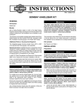
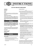
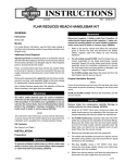
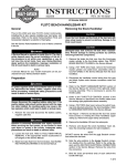
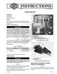
-J05280
REV. 2011-04-08
1.00 INCH (25.4 MM) DIAMETER HANDLEBAR KITS
GENERAL
Kit Numbers
57474-11, 57485-11
Models
For model fitment information, see the P&A retail catalog or
the Parts and Accessories section of www.harley-davidson.com
(English only).
NOTE
This instruction sheet refers to service manual information. A
service manual for this year/model motorcycle is required for
this installation and is available from a Harley-Davidson dealer.
Kit Contents
See Figure 4 and Table 1.
REMOVAL
Additional Parts or Accessories Required
Separate purchase of additional parts or accessories is
required for proper installation of this handlebar kit on this
model motorcycle. See the P&A retail catalog or the Parts and
Accessories section of www.harley-davidson.com (English
only) for a list of required parts or accessories for this model.
Separate purchase of a Twist Grip Sensor Kit (H-D Part No.
32310-08) is required for all models.
Replace brake line gaskets. Re-using original gaskets can
cause brake failure and loss of vehicle control, which could
result in death or serious injury. (00318a)
Motorcycles equipped with a glued left side hand grip will also
require a new grip, sold separately. Refer to the parts catalog
for replacement OE hand grips.
FLHX Models require separate purchase of handlebar-mounted
mirrors. If fairing-mounted mirrors are to be removed, separate
purchase of two small (H-D Part No. 755) and two large (H-D
Part No. 732) hole plugs is recommended.
Ask a Harley-Davidson dealer about the selection of Genuine
Motor Accessory hand grips and handlebar-mounted mirrors
(FLHX Models) that are available.
Tools and Supplies Required
Loctite® 243 Threadlocker and Sealant - Blue is required for
proper installation of this kit.
Fresh, uncontaminated DOT 4 brake fluid from a sealed container will be needed.
A long shank ball-end socket (Snap-on® FABL6E or equivalent)
will aid in the removal and installation of the radio or storage
box.
The rider's safety depends upon the correct installation
of this kit. Use the appropriate service manual procedures.
If the procedure is not within your capabilities or you do
not have the correct tools, have a Harley-Davidson dealer
perform the installation. Improper installation of this kit
could result in death or serious injury. (00333a)
-J05280
To prevent accidental vehicle start-up, which could cause
death or serious injury, remove main fuse before proceeding. (00251b)
1.
Refer to the service manual and follow the instructions to
remove the main fuse.
2.
Remove the outer fairing. See the service manual.
3.
Remove the fairing cap. See the service manual.
4.
FLHX Models: Handlebar-mounted mirrors (purchased
separately) are required for proper installation of this
handlebar. Removal of the inner fairing may be required,
refer to the service manual.
If fairing-mounted mirrors are being removed: Install the
two small black plugs and large black plugs (purchased
separately) to plug the fairing mirror holes.
Direct contact of D.O.T. 4 brake fluid with eyes can cause
irritation. Avoid eye contact. In case of eye contact flush
with large amounts of water and get medical attention.
Swallowing large amounts of D.O.T. 4 brake fluid can cause
digestive discomfort. If swallowed, obtain medical attention. Use in well ventilated area. KEEP OUT OF REACH OF
CHILDREN. (00240a)
D.O.T. 4 brake fluid will damage painted and body panel
surfaces it comes in contact with. Always use caution and
protect surfaces from spills whenever brake work is performed. Failure to comply can result in cosmetic damage.
(00239b)
NOTE
Immediately wipe up any brake fluid spillage with a clean, dry,
soft cloth. Follow up by thoroughly wiping the affected area
with a clean, damp, soft cloth (small spills) or washing with a
large quantity of soapy water (large spills).
1 of 6
Cover nearby motorcycle surfaces with an H-D Service Cover
or polyethylene protective sheet to help protect against damage
to the finish caused by spillage or splash of DOT 4 brake fluid.
5.
Drain the brake fluid from the front brake reservoir and
lines per the instructions in the service manual.
NOTE
Cover the front fender and the fuel tank with an H-D Service
Cover or clean shop towels to prevent scratching.
6.
Remove the hand grip and set it aside for installation onto
the new handlebar.
17. Remove the end cap from the right hand grip (if equipped).
Remove the hand grip from the handlebar.
NOTES
Models without Radio: Remove the storage box. See
the service manual.
The twist grip sensor in the right side of the handlebar has a
seal cap that protects internal electrodes from dirt and moisture,
and also serves as a throttle grip retainer.
b.
The four socket head screws fastening the radio or
storage box to the left and right radio support brackets
can be accessed through the oblong holes in the
fairing brackets. Use a long shank ball-end socket to
remove the screws.
Pull the radio or storage box forward to remove it from
the opening in the inner fairing.
Remove brake line components carefully. Damage to
seating surfaces can cause leakage. (00320a)
8.
16. If the left side hand grip is not glued to the handlebar:
Remove the end cap from the hand grip (if equipped).
Models with Radio: Remove the radio. See the service
manual.
a.
7.
15. Remove the left side switch housing assembly and wire
harness. Refer to the service manual.
Remove and retain the button head screw on the underside of the fork stem and bracket assembly that holds the
brake line manifold tee.
Note the front brake line routing and the orientation of the
banjo fittings. Disconnect the brake line from the front
brake calipers and the front brake master cylinder
assembly.
To remove the grip, a slight tug may be necessary to release
the index pins in the grip from the receptacle in the seal cap.
If the throttle grip is being replaced: Discard the throttle grip
and proceed to Step 16.
If the throttle grip is not being replaced: After removing the
grip, note if the seal cap is attached to the end of the twist grip
sensor.
•
If the seal cap is attached to the sensor, proceed to Step
16.
•
If the seal cap is still fastened to the index pins inside the
throttle grip, use a stiff piece of mechanic's wire to capture
the seal cap and pull it free of the index pins.
18. Remove the OE twist grip sensor and discard. Refer to
the service manual.
is00328f
1
Save the banjo bolts, but discard the two gaskets found
at each banjo fitting. See the service manual.
9.
2
6
Remove the front brake line assembly.
NOTE
Ask a Harley-Davidson dealer about the selection of Genuine
Motor Accessory Custom Braided Clutch Cables and Brake
Lines that are available.
7
10. Remove the front brake master cylinder and clutch lever
assemblies from the handlebar.
5
3
4
11. Disconnect the clutch cable from the clutch lever. See the
service manual.
Follow the instructions in the service manual to disconnect
the clutch cable from the side cover and remove the cable
from the vehicle.
NOTE
Note the harness routing and location of connector clips and
cable straps before disconnecting and removing wiring inside
the fairing.
Figure 1. Handle Clamp and Risers
12. Disconnect the handlebar control wiring from the gray
sixteen-way and black twelve-way main harness connectors inside the fairing. Refer to the service manual.
19. See Figure 1. Remove the screws (1) that fasten the
handlebar upper clamp (2) to the risers (4), and remove
the clamp. Remove the handlebar (3).
13. Remove and discard the cable straps that secure both
switch harnesses to the handlebar.
NOTE
Do not remove the wires from the Molex handlebar switch
connector pin housings inside the fairing.
14. Remove the right side switch housing assembly and wire
harness. Refer to the service manual.
-J05280
2 of 6
20. Remove riser attachments screws (5). Remove rubber
bushings (7), and washer (6) (if present). Discard cup
washers and spacers.
21. Apply a small amount of Loctite 243 (blue) to the riser
screws. Replace rubber bushings with aluminum bushings
from the kit. Install riser screws and tighten until snug. The
screws will be tightened to specification later in the procedure.
22. Note the wire colors and positions in each cavity of the
socket housings leading from the switches. Refer to the
wiring diagram and the service manual. Remove the wires
(with socket terminals) from the socket housings.
23. For internal handlebar switch wiring: Use tape to wrap
the wire terminal ends from each source to make separate
leaders. Wrap each leader tight enough to enter the wire
entrance hole at the handlebar switch location and pass
easily through the new handlebar.
INSTALLATION
Internal Handlebar Wiring
1.
Route the wires through the handlebars following the
instructions in the service manual.
NOTES
The twist grip sensor MUST be replaced with a new sensor
(H-D Part No. 32310-08), sold separately.
Reverse switch wiring for Trike models must be wired externally.
2.
Obtain the Twist Grip Sensor Kit (purchased separately).
Use tape to wrap the wire terminals on the ends of the
twist grip sensor wires to make a single leader. Wrap the
leader tight enough to pass easily through the new
handlebar.
3.
Tie the end of the string from the right side handlebar end
hole to the twist grip sensor wire bundle.
4.
Tie the end of the string from the right side switch wire
hole to the right side switch wire bundle.
5.
Apply a light coat of liquid soap, window cleaner or allpurpose lubricant to the right side switch and twist grip
sensor wire bundles.
Wiring in the switch housings must be routed exactly as
shown. Pinch points in the switch housings can shortcircuit or sever wires, which could cause loss of control
resulting in death or serious injury. (00415b)
6.
Carefully pull the wires through hole in handlebar to prevent stripping the wires. Stripped wires can cause short
circuits and damage vehicle electrical components, which
could cause loss of vehicle control resulting in death or
serious injury. (00418b)
7.
Pull the taped ends of the wire bundles through the wireexit hole at the bottom center of the handlebar.
8.
Tie the end of the string from the left side switch wire hole
to the left side switch wire bundle.
9.
If necessary, apply a light coat of liquid soap, window
cleaner or all-purpose lubricant to the left side switch wire
bundle.
10. Route the left side switch wire bundle through the switch
housing as shown in Figure 2 for the right side wiring.
Gently feed the wire bundle into the left side switch wire
hole.
Pull the bundle down through the new handlebar and
toward the center of the bar.
11. Loosely fasten the brake lever and clutch lever clamps to
the new handlebar.
12. Loosely fasten the handlebar switch housings to the new
handlebar.
13. Remove the tape from the ends of the wire bundles.
14. Check for electrical continuity between the handlebar and
each wire in the wire bundles. Continuity would indicate
a short circuit, which would require examination of the
wires and routing in the switch housing.
Proceed to Handlebar Installation.
is03096
1
3
3
Gently feed the twist grip sensor wire bundle into the right
side handlebar end.
See Figure 2. Route the right side switch wire bundle
through the switch housing as shown. Gently feed the wire
bundle into the right side switch wire hole.
Pull the bundles down through the new handlebar and
toward the center of the bar, while fitting the index tabs
on the twist grip sensor into the slots on the end of the
handlebar. One index tab and slot are smaller than the
other to aid in proper assembly.
-J05280
2
1. Upper switch housing screw
2. Lower switch housing screw
3. Pinch points
Figure 2. Switch Housing Wire Routing (Right Side Housing
Shown)
3 of 6
Handlebar Installation
1.
Center the new handlebar on the risers. Verify that the
knurled handlebar areas exposed on the outboard side of
each riser are equal.
2.
Position the original handlebar upper clamp and loosely
install with the clamp screws saved earlier.
3.
Rotate the handlebar forward until the handlebar contacts
the inner fairing. Rotate handlebar back until there is a
gap 1/8" to 1/4" away from the inner fairing.
1
6
is04809
3
5
2
4
7.
Connect the gray handlebar switch wire socket housing
to the gray pin housing inside the nacelle. Connect the
black handlebar switch wire socket housing to the black
pin housing inside the fairing.
8.
Obtain the PVC tubing and the six-way black Molex pin
housing from the Twist Grip Sensor Kit (purchased separately). Install the tubing over ALL of the wires coming from
the twist grip sensor.
9.
Insert each pin terminal from the twist grip sensor into the
correct cavity of the pin housing as follows:
From the yellow conduit,
a.
Black wire to cavity 1
b.
White wire to cavity 2
c.
Red wire to cavity 3
From the black conduit,
7
9
10
a.
Black wire to cavity 4
b.
White wire to cavity 5
c.
Red wire to cavity 6
Position the PVC tubing installed in Step 7 in the area of
the radio or storage box. The tubing will be moved to the
proper location at final assembly.
8
1.
2.
3.
4.
5.
6.
7.
8.
9.
10.
Snug left front screw
Snug right front screw
Tighten left front screw
Tighten right front screw
Tighten right rear screw
Tighten left rear screw
Front of vehicle
Original handlebar riser
Handlebar
Original upper handlebar clamp
Figure 3. Handlebar Clamp Screw Tightening Sequence
NOTE
The handlebar upper clamp is designed to leave a gap between
the clamp and riser to the rear of the handlebar when installed.
4.
See Figure 3. Snug, but do not fully-tighten, only the front
two upper clamp screws in the following sequence:
a.
First, snug the left front screw (1).
b.
Then, snug the right front screw (2).
5.
Refer to the notes made during the removal steps, and
the wiring diagram and the service manual. Insert each
socket terminal from the left side switch wire bundle into
the correct cavity of the gray socket housing removed
earlier.
6.
Insert each socket terminal from the right side switch wire
bundle into the correct cavity of the black socket housing
removed earlier.
10. Connect the six-way black Molex pin housing from the
twist grip sensor to the black six-way socket housing inside
the fairing.
Improperly aligned handlebars or components can contact
the fuel tank when turned to the left or right. Contact with
the fuel tank can cause cosmetic damage. (00372b)
11. Slowly turn the front wheel to the full-right fork stop and
then the full-left fork stop to be sure the handlebar does
not contact the fuel tank. If contact occurs and the
handlebars are properly centered, raise the handlebar
angle as necessary until proper clearance is attained.
12. Tighten the riser screws to 30-40 ft-lbs (41-52 Nm).
NOTE
The upper handlebar clamp screws MUST be final-tightened
in the following sequence to make sure proper clamping is
achieved.
NOTE
It may be necessary to disconnect the wire harness housings
from the fairing supports. After connecting the pin and socket
housings tie wrap the wiring to secure it inside the fairing.
-J05280
4 of 6
13. See Figure 3. Tighten the upper handlebar clamp screws
as follows:
a.
Tighten the left side front screw (1) until the left side
of the handlebar clamp makes contact with the front
of the left side handlebar riser.
Avoid leakage. Be sure gaskets, banjo bolt(s), brake line
and caliper bore are clean and undamaged before
assembly. (00321a)
b.
Tighten the right side front screw (2) until the right
side of the handlebar clamp makes contact with the
front of the right side handlebar riser.
1.
Carefully inspect the new (sold separately) brake line for
damage or defects, and replace if damaged. Install following the instructions included with the brake lines.
c.
Tighten the left side front screw (3) to 16-20 ft-lbs
(21.7-27.1 Nm).
2.
Bleed the brakes. See the service manual.
3.
d.
Tighten the right side front screw (4) to 16-20 ft-lbs
(21.7-27.1 Nm).
Install the new clutch cable (sold separately) following the
instructions included with the clutch cable kit.
4.
e.
Tighten the right side rear screw (5) to 16-20 ft-lbs
(21.7-27.1 Nm).
Models with Radio: Install the radio. See the service
manual.
f.
Tighten the left side rear screw (6) to 16-20 ft-lbs
(21.7-27.1 Nm).
Models without Radio: Install the storage box. See the
service manual.
5.
Position the PVC tubing on the twist grip sensor wires
(previously installed) to prevent chafing of the twist grip
sensor wires against the heat sink fins on the radio (if
equipped) and the sharp edges of the radio or storage box
mounting bracket inside the fairing.
14. Install a new (purchased separately) or original handlebar
grip on the left end of the new handlebar following the
handlebar grip instruction sheet or the service manual.
6.
Install the fairing cap. See the service manual.
7.
Install the outer fairing. See the service manual.
15. Adjust the positions of the switch housing and the clutch
lever assembly on the handlebar for rider comfort.
8.
FLHX Models: Install handlebar-mounted mirrors following
the instructions in the service manual.
16. Tighten first the top, then the bottom clutch-lever clamp
screws to 72-108 in-lbs (8.1-12.2 Nm).
SAFETY CHECK
NOTE
There will be a slight gap between the upper clamps and the
risers toward the rear of the handlebar after tightening.
17. Tighten first the lower, then the upper switch housing
screws to 35-45 in-lbs (4.0-5.1 Nm).
18. Install the new (purchased separately) or original right
grip/throttle sleeve. Refer to the service manual.
Be sure that steering is smooth and free without interference. Interference with steering could result in loss of
vehicle control and death or serious injury. (00371a)
19. Adjust the position of the switch housing and the brake
lever assembly on the handlebar for rider comfort. The
brake master cylinder must be level.
•
Be sure wires, clutch cables and brake lines do not pull
tight when handlebars are turned fully to the left or right
fork stops.
NOTE
Tighten the top brake lever clamp screw before tightening the
bottom screw.
1.
Verify that the ignition key switch is turned to the OFF
position.
Install the main fuse. Refer to the service manual.
20. Tighten first the top, then the bottom brake lever clamp
screws to 72-108 in-lbs (8.1-12.2 Nm).
NOTE
Tighten the lower switch housing screw before tightening the
upper screw. This will leave any gap in the switch housing at
the front for best appearance.
21. Tighten first the lower, then the upper switch housing
screws to 35-45 in-lbs (4.0-5.1 Nm).
22. Verify that the right grip/throttle sleeve rotates and returns
freely and does not bind on the handlebar or switch
housing.
FINAL ASSEMBLY
Be sure that all lights and switches operate properly before
operating motorcycle. Low visibility of rider can result in
death or serious injury. (00316a)
2.
Turn the ignition key switch to IGNITION, but do not start
the motorcycle. Test each handlebar switch for proper
operation.
3.
Turn the handlebar to the left and right steering stops,
testing the handlebar control functions at each stop.
4.
Apply the front brake hand lever to test operation of the
brake lamp.
Replace brake line gaskets. Re-using original gaskets can
cause brake failure and loss of vehicle control, which could
result in death or serious injury. (00318a)
-J05280
5 of 6
Before starting engine, be sure throttle control will snap
back to idle position when released. A throttle control that
prevents engine from automatically returning to idle can
lead to loss of control, which could result in death or serious injury. (00390a)
After repairing the brake system, test brakes at low speed.
If brakes are not operating properly, testing at high speeds
can cause loss of control, which could result in death or
serious injury. (00289a)
SERVICE PARTS
is04810d
1
C
B
A
2
D
Figure 4. Service Parts: Handlebar Kits
Table 1. Service Parts, Handlebar Kits
Kit
Kit 57474-11
Kit 57485-11
Item
Description (Quantity)
Part Number
1
Handlebar
Not sold separately
2
Handlebar bushing (4)
Not Sold Separately
Items mentioned in text, but not included in kit:
A
Original equipment handlebar riser (2)
B
Original equipment upper handlebar clamp
C
Original equipment handlebar clamp screw (4)
D
Screw (2)
Kit 32310-08 - Twist Grip Sensor Kit (Purchased Separately)
The Heated Hand Grip items below are not used with these Handlebar Kits, and can be discarded:
Socket housing, two-way
Secondary lock, two-way socket housing
Seal pin (plug) (2)
Pin housing, two-way
Secondary lock, two-way pin housing
-J05280
6 of 6