1
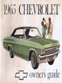
1965 CHEVROLET
I
:
:
I
owners guide
www.carburetor-manual.com
Would you like some Free Manuals?
http://carburetor-manual.com/free-shop-manual-club-t-13.html
Also visit http://freeshopmanual.com for more Free Manuals
Also Visit my website for 7 FREE Download Manuals starting
with this one.
"The ABC's of Carburetion"
Click Here Now
file:///C|/Documents%20and%20Settings/Tim/Desktop/carburetor-manual-welcome/index.htm[4/25/2009 11:42:20 AM]
A WORD FROM CHEVROLET ...
This 0 wners Guide contains important information regarding the operation
and maintenance of your Chevrolet.
In order to obtain maximum en;oyment and usage from your car, we suggest
that you familiarize yourself with the contents of this booklet and follow the
recommendations outlined.
Your Chevrolet dealer has the tmined personnel and speCialized equipment
to properly service yo",' Checrolet. Have him inspect your car and perform
any maintenance 01' ad;ustments required.
We would like to take this opportunity to thank you for choosing a Chevrolet
product-and assure you of our continuing interest in your motoring pleasure
and satisfaction.
CHEVROLET MOTOR DIVISION
•
GENERAL MOTORS CORPORATION
DETROIT, MICHIGAN 48202
SECOND EDITION
NOVEMBER, 1964
CONTENTS
Page
Operating Instructions . , . . ..... . ... . .... . 4 thru 7
Instruments ... . .... , ...... . .......... . 8 thru 11
Controls ........... . ..... . ...... . .. . . . 12 thru 21
Other Features ......... , ..... _ . . ..... . 22 thru 24
Station Wagon and Convertible .... . . . ... . 25 thru 28
Cleaning Your Chevrolet .... . . . . . . . . ... . . 29 and 30
Maintenance and Lubrication ...... . . ,... 31 thru 40
Minor Trouble Shooting .. . .. ... . ..... . .. 41 thru 44
Specifications ..............•. • . ........ 45 thru 47
Index .. . .... . ................... . ... . ..... . 48
All information contained in this baoHe! is the latest prod.
!Jct information ovailable 01 the lime of printing. The righ t
is reserved to make changes 01 any lime without notice.
2
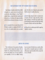
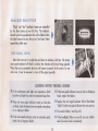
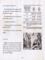
YOUR CHEVROLET'S FIRST FEW HUNDRED MILES OF DRIVING
Sound design and precision manufacturing methods
speed, either fast or slow. During th is period, avoid full
throttle starts and, if possible, abrupt stops.
will permit you to operate your new Chevrolet from its
very first mile without adhering to a formal "break-in"
schedule. However, during the first few hundred miles of
driving you can, by observing a few simple precautions,
add to the future performance and economy of your car.
• Gentle braking during the first few hundred miles
of operation will result in longer brake life and better
future performance. A void hard stops especially during
the first 200 miles of operation since brake misuse during
this period will destroy much future brake efficiency.
• It is recommended that your speed during the first
500 miles be confined to a maximum of 60 M.P.H., but
do not drive for extended periods at anyone constant
• Always drive at a moderate speed until the engine has
completely warmed up.
DRIVING FOR ECONOMY
Proper maintenance and wise opera60n will combine
to help you achieve max imum fuel economy with your
Chevrolet. Your Authorized Chevrolet Dealer can prop~
erly tune and maintain your car but wise operation is
your responsibility. Give the car sufficient wann~up
time, do not make full throttle starts or needless sudden
stops, and drive at reasonable speeds and as steadily as
traffic permits to gain the benefits of all the economy built
into your Chevrolet.
3
OPERATING INSTRUCTIONS
SWITCH OFF
AND LOC KED
ACCESSORY
DRIVING
POSITION
/
ON
START
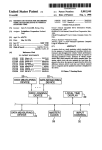
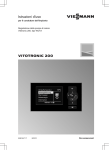
STARTING THE ENGINE
POWERGLIDE TRANSM ISsi oN - Place selector lever in N or P position. The
engine will not start when lever is in any other position.
MANUAL TRANSMISSION - Place gearshift control lever in Neutral and depress
clutch pedal to the floor.
•
ENGINE COLD-depress accelerator pedal
to floor and release. This presets the automatic choke.
•
ENGINE HOT-depress the accele rato r
WARM-UP
ACCESSORIES
ONLY
STARTI N G
ENGINE
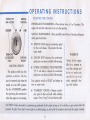
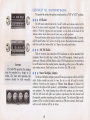
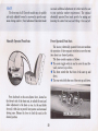
IGNITION SWITCH
The ignition s\vitch has four
positions as shown. The key
may be removed only when the
switch is in the OFF position.
Use the ACCESSORY position
for operating the accessories
when the engine is not rmming.
pedal part way down and hold while starting.
•
DURING EXTREMELY COLD WEATHER
(00 F. and below)-depress the accelerator
pedal part 'w ay down and hold whiJc starting.
Turn ignition switch to START and release as
soon as engine starts.
•
Always let the engine
idle for a moment or
two after starting and
drive at moderate
speeds for several
miles, especially during cold weather.
"FLOODED" ENGINE - Depress accelerator pedal to Roor and hold while cranking
engine. Never "pump" the accelerator pedal.
CAUTION: Carbon monoxide is a poisonous gas produced by· the engine of any car. It -is odorless, so you cannot detect its
presence. Be safe. Never start or nm engine in a closed garage, or park with the windows closed and th e engine running.
4
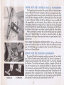
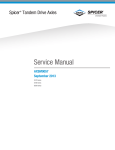
DRIVING WITH THE CHEVROLET MANUAL TRANSMISSIONS
The 3-speed manual transmission shift positions follow the standard pattern
shovvn at the left . The 4-speed transmission shift leve r, extending from the floor.
has its special shift pattern diagram located on th e floor plate. Depress the clutch
pedal fully before attempti ng to shift to a different gear, th en release the p edal
~~ ~ili a t _. ~~i~~ ~ ~ _a=a~ ~~
add appreciably to your fu el economy. Always shift into a lower gear, when
slO\ving down, before the car begins to "lug" or labor and also when descending
steep hills. Shift into 1st (except with 4-speed ) or Reverse gear only after the car
has stopped. Al ways depress and release the clutch pedal full y when shHting.
\Vh en a push start is necessary turn off aU electrical loads such as heater,
radio, and. jf possible, lights, turn on th e key, depress the clutch, and place
the shift lever in 3rd gear. Release the clutch when your speed reaches 10 to 15
miles per hour.
FOUR SPEED TRANSMISSION REVERSE SHIFT - Lift up on the reverse
release cable handle just below the shi ft lever knob when shifting into reverse
gear. The shift li nkage may be adjusted to allow "short stroke" shift lever operati on. See your Chevrolet Dealer.
DRIVING WITH THE OVERDRIVE TRANSMISSION
LOCKED OUT
IN OPERATION
The optional Overdrive transmission provides an automatic 4th, or cruising,
gear. \Vith the Ove rdrive control handle pulled "out," the unit is operating as a
standard 3-specd transmission. Push the handle full y "in" at any time to engage
the Overd ri ve. The un it th en wiII operate as follows: At speeds of 30 mph and
over, the transmission may be automatically shifted into 4th gea r by momentarily rele~ls i n g the accelerator pedal Shift back into 3rd gear for fast accelerati on by momentaril y Hooring th e accelerator peda1. Below 26 mph the unit will
automati call y retUn1 to standa rd drive. To lock Overdrive out while moving,
Roar the accelerator pedal mom entaril y and , at the same time, pull out the Overdrive handl e. For push stalt s, the handle should be full y "out."
5
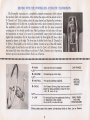
DRIVING WITH THE POWERGLIDE AUTOMATIC TR4.NSMISSION
The PowergHde transmiss ion is a completely automa tic transm ission which replaces
the standard clutch and transmission. After starting the engine with the selector lever in
N (Neutral) or P (Park) position, select the range desired and depress the accelerator.
The tran sm ission will do the rest. A gradual start with a steady increase of pressure on
the accelerator pedal will enabJe th e transmiss ion to shift into the more economical
cruising gear in the shortest possible time. Hard acceleration for fast starts will cause
the transmission to remain in low gear for a conSiderably longer period with resultant
higher fuel consumpti on. On the Super-Sport model the Powerglide shift lever is floor
mounted as shown at the right. The lever may be shifted freely from N (Neutral) to
D (Drive) . Press lightly on tl,e shift lever button (located on top of the shift handle)
with the palm of your hand as you shift into or out of L (Low) or R (Reverse). Force
tillS button full y down when shiftin g to and from P (Pa rk ). Exercise care in depressing
button to prevent un in tentional shifts to Park , Low or Reverse .
...............................................................
P-PARK
Use only when car is stopped.
CAR PARKED
- ' LIFT-------------------------------------------------------R-REVERSE
For backing car-from stop.
-' LIFT--------------------------------- ---------NORMAL
N-NEUTRAL
For standing ( Bra kes Applied).
DRIVING
RANGE
D-DRIVE
For Forward Driving. Step hard on accel-
erator for extra acceleration below 45 mph
-VB, 40 mph-6 cyl.
-'LlFT--------------------------L-LOW
For hard pulling at low speeds and clim bing
SAND, SNOW,
MUD AND
or descending steep grades.
STEEP GRADES
00 not sh ift to L above 40 mph .
· Ufting clea rs stops that prevent unintentional shifts to Park , Low or Reve rse.
6
•
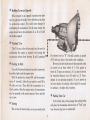
Holding Car on an Upgrade
When stopped on an upgrade. maintain your pos ition by applying the brakes. Never hold the car in place
by accelerating engine. This could cause damage by
overheating the transmission. For the same reason, the
engine should never be accelerated in L, D or R with
the brakes engaged.
•
"Rocking" Car
"Rock" the car to free it from mud, sand or snow by
accelerating the engine as required and moving the
transmission selector lever between D and R positions.
•
the selector lever in "N" (Neutral ) position at speeds
of 35 miles per hour or less under most conditions.
However, the drive shaft must be disconnected or the
car towed on its front wheels if 1) Tow speeds in
excess of 35 mph are necessary, 2) Car must be towed
for extended distances (over 50 miles) or, 3) Transmission is not operating properly. If car is towed on
its front wheels, the steering wheel should be secured
to maintain a straight ahead position.
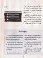
Pushing to Start
Turn off all electrical loads such as radio, heater and,
if possible, lights until the engine stalis.
\Vith the ignition key turned ON and the transmission in N (neutral), allow the car speed to reach 25 to
30 miles per hour. Then shift the transmission to L
(low) position. After the engine starts, the transmission
may be operated in the norma1 manner. Never tow the
car to start.
•
•
Parking Your Car
To be doubly safe, always engage the parking brake
and place the transmission selector lever in "Park" position when leaving your car unattended.
Towing
The car may be towed safely on its rear wheels with
7
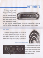
INSTRUMENTS
The instruments, gauges and warning
lights conveniently grouped in the instru~
ment cluster are designed to tell you at a
glance many important things about the
performance of your car, The information
on this and the following two pages will
enable you to more quickly understand
and properly interpret these instruments. Familiarize
yourself with their location and purpose and make it a
practice to scan the instrument cluster as you start the
engine, after it starts, and periodically as you drive.
FUEL GAUGE
This electrically operated gauge indicates the level of fuel in the fuel
tank. The gauge reg isters correctly when the ignition switch is in the "on"
position, \¥hen the ignition switch is turned "off," the needle will not
necessaril.y return to the empty mark but may stop at any point on the dial.
~
~
W
-
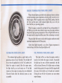
SPEEDOMETER AND ODOMETER
-
1~ Jij I~ \~ ~ij m !ij !ij lijij
'"- '-" " " ' \ ' \ ' \11 11/ 1 1 / / / / /
.
I\ij
/
\1ij
/
.0 00001)'
8
The speedometer indicates the speed of the
car in miles per hour. The odometer, or mileage
ind icator, registers accumulated mileage and is
useful for checking trip mileages, maintenance
periods and fuel consumption,
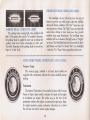
ENGINE TEMPERATURE INDICATOR LIGHTS
These indicator Jights are provided in th e instrument cluster to indicate
a Donnal operating engi ne temperature and also quickly warn of an overheated engine. With the ignition switch in the START position, both the
red ( hot) and the green (cold) indicator lights will go on to let you
know that they are operating properly.
\Vhen the engine is started, the red light will tum off immediately. It
will light up at no other time unless for some reason the engine reaches a
dangerously high operating temperature. If the red light should come on,
the engine must be stopped until the cause of the overheating is corrected.
The green light will remain on only until the engine reaches its Donnal
operating temperature and will then go out.
Check these lights frequently as you drive. Engine temperature is
normal as long as both the red and green lights are off.
GENERATOR INDICATOR LIGHT
OIL PRESSURE INDICATOR LIGHT
This indicator light provides a quick check on the
generating system of your Chevrolet. The red light will
be on when the ignition key is in the "on" position, but
before the engine is started. After the engine starts,
the light should go out and remain out. If the light
remains on when engine is running, have your Authorized
Chevrolet Dealer check the electrical system as soon
as possible.
This light will be on when the ignition switch is
turned on but before the engine is started. Occasionally
the light may be seen to Ricker momentarily, but this
will do no harm. However, if the light remains on during
nonnal driving speeds, the engine should be stopped until
the cause of the trouble can be located and corrected.
Driving the car with low oil pressure can cause serious
engine damage.
9
HEADLIGHT BEAM INDICATOR LIGHT
The headlights of your Chevrolet h ave two sets of
beams to provide you with proper night~time visibility
durin g all driving conditions. The «low" beams are used
during most city driving. The "high" beams are especially
useful when drivin g on dark roads since they provide
excellent long range illumination . The headlight beam
indicator will be on wh enever the hi gh beams or "brights"
are in use. The Headlight Beam Switch controls the h eadlight beams (see Page 13). Always "dim" your headlights
- switch to "low" be.'1m- when approachi ng other cars.
PARKING BRAKE INDICATOR LIGHT
The parkin g brake warn ing light, when installed, will
flash ( jf the ign ition key is in the "on" position) whenever
the parking b rake is applied to warn you to release the
parking brake lever before at tempting to drive your
Chevrolet. Operation of the parking brake is covered on
Page 14 of this book.
SUPER SPORT MODEL INSTRUMENTS AND GAUGES
Vacuum Gauge
The vacuum gauge, installed in all Super Sport models not
equipped with a tachometer, indicates the engine manifold vacuum
readin g.
Tachometer
The optional Tachometer. when installed in place of the Vacuum
Ga uge on Super Sport models, indicates the speed of the engine
in revolutions per minute. The yellow area on the face of the
tachometer indicates the highest recommended engine rpm. Regular engine operation causing tachometer indications in or above
the red area C:'1n lead to serious engine damage.
10
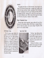
Ammeter
The ammeter shows the rate at which the battery is being charged or discharged. The Deleotron charging system is equipped with a regulator which
controls the ch arge according to battery requirements. \Vhen the Deleotron
generator is supplying more than the current clemand, the ammeter will show
the charging rate while a discharge will be shown if the current demand is
more than the Delcotron output. With the battery fully charged, the charging
rate will be low, thus giving an indication of battery condition.
Engin e Temperature Gauge
ShO\ving engine coolant temperature, gauge readings will vary with air
temperature and operating conditions. Hard driving or prolonged idling in
very hot weather may produce above nonnal readings. The ignition switch
must be on for accurate readings.
Oil Pressure Gauge
The oil pressure gauge indicates the
pressure at which oil is being delivered to
the various parts of the engine requiring
lubrication. Pressures registered by the
gauge may vary according to outside air
temperatures or weight of oil being used.
Oil pressure of a cold engine being operated
at a given speed wil1 be somewhat higher
than when the engine is at nonnal operating
temperature at the same speed. Prolonged
high speed operation on a hot day at the
given speed will result in somewhat lower
oil pressure readings.
Super Sport Clock
The Super Sport rally-type clock,
its face designed for both twelve and
twenty-four hour readings, is located on
the center console. The clock is also
calibrated for accurate minute and second indications.
Setting and adjusting is accomplished in the same manner as for docks
used on other models (See page 22).
11
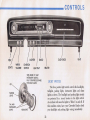
CONTROLS
LIGHTS
WIPER
WASHER
IGNITION
SWITCH
_-..~
PARKING
LIGHTS
ASH TRA Y
TURN KNOB TO VARY
INSTRUMENT LtGHTSFULLY COUNTERCLOCKWISE
FOR DOME LIGHTS
LIGHT SWITCH
The three position light switch controls the headlights,
taillights, parking lights, instrument lights and dome
lights as shown. The headli ght and parking light circuits
- - - . !.",
are protected by a circuit breaker in the light switch.
TAIL AND
INSTRUMENT
LIGHTS
~
An overload will cause the lights to "/licker" on and off. If
this condition exists, have your Chevrolet Dealer check
your headlight and parking light wiring immediately.
~"",,::::::::::::..-_.....-:
12
HEADLIGHT BEAM SWITCH
"High" and "low" headlight beams are controlled
by the floor button at your left foot. The indicator,
located below the speedometer dial, will be lighted when
•
the high beams are in use. Always use <'low beam" when
approaching other cars.
TURN SIGNAL LEVER
Move the lever up for a right turn and
ment panel indicators will Hash to indicate
When the turn is completed, the lever will
wide tum, it may be necessary to tum off
down to indicate a left tum. The instruthe direction of the tum being signaled.
return to neutral. In the event of a very
the signal manually.
LIGHTING SYSTEM TROUBLE CHECKS
• If the instrument panel lights are inoperative. check
both the taillight fuse and the insh'ument lamp fuse.
• If the tum signal indicator comes on but no clicking is
heard, replace the flasher.
•
• Replace the tum signal indicator bulb if the flasher
'W'hen the tum signal indicator comes on but does
not flash, check for burned out tum signal or stop lamp
or an improper flasher.
«clicks" but the tum signal indicator does not come on.
• Use correct flasher (see Page 45).
• If the tum signal indicator action is extremely rapid,
• If the headlights flicker on and off, see your Author-
check for an improper flasher.
ized Chevrolet Dealer immediately.
13
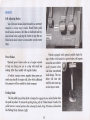
BRAKES
Self Adjusting Brakes
Your Chevrolet brakes adjust themselves as necessary
whenever a reverse stop is made. Should brake pedal
travel become excessive, drive the car backward and forward several times applying the brakes to stop the car.
Pedal travel should return to normal after several reverse
stops.
Vehicles equipped with optional metallic brake lin-
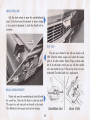
Power Brakes
ings, whether with standard or power brakes, will require
somewhat more relative
pedal pressure when
cold than conventional
Optional power brakes make use of engine vacuum
to help you bring your car to a stop with much less
braking effort than needed with regular brakes.
brake linings. This condition will exist only
until the units wrum up ,
several stops at most.
A built-in vacuum reserve supplies three power assisted stops should the engine stall, after which additional
foot pressure will he need ed for brake response.
Parking Brake
The foot pedal type parking brake is designed to engage the rear wheel brakes when
the pedal is pushed. To release the parking brake, pull the "Brake Release" handle. The
pedal returns to normal position after releasing the brake. Page 10 locates and describes
the Parking Brake Indicator Light.
14
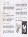
CLUTCH ADJUSTMENT
Keep the water container under the hood filled at all
times. Avoid operating the washer when jar is empty,
G. M. Windshield Washer Solvent added to the water
aids in cutting road £1m and grease from the windshield
and is recommended for use at all times except when the
temperature falls below freezing,
Clutch adjustment should be checked and adjusted
periodically as necessary to compensate for clutch facing
wear. To check, depress pedal by hand until resistance is
felt. F ree h·avel of pedal should be approximately ~ inch;
if very little or no free travel is evident, clutch adjustment
is required.
When the temperature falls below freezing, G. M.
Windshield Washer Anti-freeze should be used. Even so,
before attempting to use the washers during freezing
weather, it is best to first prewarm the windshield by
means of the heater defrosters.
WINDSHIELD WIPER
Turn the control knob clockwise to start the singlespeed electric 'windshield wiper. Turn the knob counterclockwise to stop the wiper. The optional tvvo-speed
electric wiper is operated in a similar manner but has
both a "low" and a «high" speed position.
Fill the washer jar only 3,4 full during the 'w inter to
allow for expansion if the temperature should fall low
enough to freeze the solution.
WINDSHIELD WASHER
On cars equipped with a windshield washer. the
operating button is located in the center of the wiper
control knob. Pressing the button will send a measured
amount of water or other cleaning agent onto the
windshield and will also cause the wiper knob to tum,
thus starting the wiper motor, The wiper will then continue to operate until manually turned off at the wiper
knob.
15
CHEVROLET "ALL TRANSISTOR" RADIOS
II 10 91 1111 I!i
To operate the radios, th e ignition switch must be in "ON" or "ACe" position.
~,L I5I
• • • AM .Radios
EMil
I
I 96_
100_
104 _
1081I
1 00_9;_
Antenna
For best FM operation the antenna
must be extended to a length of 31
inches. For best AM operation the
antenna should be fully extended.
The left hand control knob is the "on·off" switch and volume control. At its
base is the ton e control wing knob. The right hand knob is th e manual station
selector. \Vith the optional rear seat speaker, a wing knob at th e base of the
station selector knob allows use of front, rear or both speakers.
Five push buttons allow station selection in th e Push Button radio. To preset,
pull the push button "out" as far as it will go, tun e in the desired station manuaJly
and then push the button fully "in." Repeat fo r each push button.
•
•
•
AMjFM Radio
This set receives clear static-free FM broadcasts as well as standard AM
programs. Move the slide bar to select AM or FM reception. Controls are the
same as in Manual and Push Button radios. FM broadcasts may be received as
far as 60 miles from the sending station, depending on the power of the station
a nd existing terrain. Push buttons may be set for AM , FM or both.
•
•
•
Stereo Multiplex Adapter
The Stereo Mu ltip lex Adapter permits FM stereo reception with the AM / FM
radio. Radio controls are used to turn the set on and off and for station
selection. Controls on the adapter are Volume, Tone, Balance (to balance the
volume of the right and left speakers), and Front-Rear (to balance the front and
rear speake rs). For most pleasing stereo effect the speakers are criss -crossed ,
w ith the left front and ri ght rea r speakers reproducing the left chann el and
the opposite speakers reproduci ng the right chan nel. The indicator light on the
adapter will be on when the radio is tun ed to an FM stereo station. Most broadcasts on such stations will be in stereo.
16
Push the AlR-F AN lever to the right to "AIR" to
allow outside air to pass through the heater Further
movement of the lever operates the low, medium and
high speeds of the fan.
HEATER
O~
~
~
~
--
~
Adjust TEMP lever as required to give the desired
T[MPERATURE
COLD
ofiiiii!;= = = = = = : J
Off
g =
HOT
DEFROSTER
degree of heat. Full right position provides maximum heat.
Move the DEF lever to the right when windshield
DE-ICE
defrosting is needed. Full right position diverts the entire
air flow to the defroster. Vary TEMP lever as required.
Heater Operating Tips
The Chevrolet heater draws outside air from the
culation, operate fan on low or medium speeds for
normal operation and high speed for quick warm-up
and during extremely low temperatures.
air inlet in front of the windshield. Always brush snow
from this inlet before operating the heater.
Keep all windows and vents closed to eliminate
For adequate rear seat heating the area beneath the
dust. road and wind noise and uncomfortable drafts.
front seat must not be hlocked hy carpeting, rags,
paper or other material.
Operate the heater for several minutes before turning on the defroster.
For additional summer ventilation move the DEF
and AIR levers to fully open and operate the fan as
For most satisfactory heater operation and air cir-
desired.
17
FOUR SEASON Am CONDITIONING
Optional Four Season Air Conditioning blends
heating and cooling units into a single system to
Heating
provide complete comfort control during any
season of the year.
Cooling
- -
~
For maximum heat, move the lower two knobs fully
right (the upper knob will move automatically to OUTSIDE air position) and push the FAN switch fully
down. Heated air will Bow through the heater Hoor dish'ibutor outlet.
Vary the heater output to satisfy your comfort requirements by moving the FAN switch and the TEMPERATURE knob as required.
To defrost, operate the heater as described above,
but with the upper knob moved {uny right to divert the
entire airflow to the defroster outlets. Moving the knob
back toward the left will split the airflow between the
defroster outl ets and the floor di stributor outlet in proportion to the movement of the knob.
See the heating tips on page 17.
For maximum cooling capacity when. first turning on
the system and during periods of extreme heat and humidity, move all three knobs fully left and push the FAN
switch fully dovlln. Cooled, recirculated air flow will enter
the car through the adjustable instrument panel outlets.
During periods of less severe heat and humidi ty, the
upper knob may be set on the vertical mark to the left
of the word AIR to blend in a portion of outside air.
During more temperate weather conditions, move the
upper knob to the word OUTSIDE for full outside air.
Vary the FAN switch (which must be tumed "on"
during cooling operations) and the TEMPERATURE
knob as necessary to satisfy your comfort requirements.
It is possible, to set the TEMPERATURE knob high
enough to provide warmed air through the dash outlets.
During marginal weather conditions, set the control knobs as
shown to supply heated air at the Roor and cooler air at the dash
outlets. Vary temperature control and fan speed as desired.
Bi-Level
Operation
~-~
18
Four Season
System
Conditioned
Air Outlets
The balTe} type center outlet may be tumed to direct
air Row up, down, straight out or shut off completely.
tioned airflow to the floor,
The ball type outlets at the ends of the instrument
panel may be rotated to supply either a direct or a
diffused air Rowand may be positioned to provide a complete shutoff.
open the swivel cover on
the bottom of the conditioner air duct as shown at
the right.
For
additional
condi-
CUSTOM AIR CONDITIONING SYSTEM
To operate the Custom Air Conditioning System:
•
Turn the FAN knob to control the three-speed blower
•
The TEMP-COOL knob may be regulated to provide
the degree of cooling desired. Fully clockwise provides
as desired.
maximum cooling.
AIR·CONDITIONER OPERATING TIPS
For most efficient cooling when driving at elevations
Close all windows and vents when operating the
system except for the first few minutes of operation
when the car interior is very hot . Close the windows as
soon as the excessively heated air has escaped.
of 4000 feet or more, move the TEMPERATURE knob
on the Four Season System about J<" to the right of the
maximum cold position. On the Custom System, turn the
TEMP-COOL knob slightly counterclockwise.
19
SEATS
The front seat of all Chevrolet models may be quickly
can make additional adjustments to further tailor the seat
mum driving comfort. (Your Authorized Chevrolet Dealer
to your particular comfort requirements.) The optional
electrically operated front seats provide for raising and
lowering the entire front seat and tilting it fore and aft.
Manually Operated Front Seats
Power Operated Front Seats
and easily adjusted forward or rearward to provide maxi-
The six-way electrically operated front seat combines
the operation of three separate switches to move the seat
into almost any desired position.
The three controls operate as follows:
•
The center toggle switch is used to move the seat forward. rearward, up or down.
• The front switch tilts the front of the seat up and
down.
•
Press backward on the seat adjuster lever) located on
the driver's side of the front seat, to unlock the seat and
allow adjustment to the front or rear. As the seat slides
forvvard, it tilts also to provide best posture and increased
driving ease. Release the lever to lock the seat in the
desired position.
20
The rear switch tilts the rear of the seat up and down.
KEYS, DOORS AND LOCKS
The octagonal-end key operates the ignition switch,
front door locks and all station wagon tailgates of your
Chevrolet.
The round-end key operates the locks for the g10ve
box, seat divider comparbnent on Super Sport models,
trunk and, on two seat station wagons, the optional luggage space lid lock.
IGNITION AND
DOOR LOCKS
Each key has a removable knockout plug on which is
stamped its serial number. Record this number so that
you may have duplicate keys made in the event that the
originals are lost. After recording the number of each key,
it is recommended that you remove the knockout plug,
using a hammer and punch, and discard it so that your
key cannot be duplicated by anyone else.
ALL OTHER
LOCKS
Unlock the doors from outside by means of the ignition key (front only) or from inside by lifting up on the
inside locking button.
Door Locks
Chevrolet door locks are designed for passenger safety
as well as to assure the security of your car and your
possessions. Always keep the doors locked when driving
as well as when leaving the car unattended.
The front doors , whether locked or unlocked, may be
opened from inside by lifting the inside door release
handle.
.
To lock each door from the outside, depress the inside
locking button, hold the outside door handle opening
button fully down and Rnnly close the door. Lock doors
from inside by depressing the locking buttons located on
the window siBs.
The rear door release handles are inoperative whenever the inside locking button is depressed. This button
must be lifted before the rear doors can be opened from
either inside or outside. (This feature is of particular
value if young children ride in the back seat.)
21
OTHER
AIR VENTS
ASH TRAY AND CIGARETTE LIGHTER
The air vents in each kick panel admit air from the
vent grille just ahead of the windshield. Control knobs
shown below open and close the vents.
Four Season Air Conditioning equipped cars have
no control knob for the right hand vent since the vent is
a part of the air conditioning system.
Pull on the lower edge of the ashtray to open. To
remove the tray, pull fully out and then toward the right.
To install, insert tray in opening and push back into place.
On cars so equipped, push in on the cigarette lighter to
operate. \Vhen heated ready for use, it will "snap" back
into normal position.
COMFORT TILT STEERING WHEEL
Lift the control lever of the optional Comfort Tilt
seven position steering wheel to move the wheel up, thus
allowing you greater ease of entry and exit.
Adjust the wheel for maximum comfort by holding
the control lever up while
moving the wheel to the
desired position, and then
releasing the lever to lock
the wheel.
Vary the wheel position
frequently during long
drives. You'll finish your trip
less fatigued and more alert.
CLOCK
Reset the clock, if your car is so equipped, by pulling
out the knob and turning the hands clockwise if slow,
counterclockwise if fast. This will, if the clock error is
three minutes or more, automatically compensate for
time gain or lag. Several resettings, several days apart,
may be needed to properly adjust the clock mechanism.
Have your clock cleaned and oiled by a competent clock
serviceman at least every two years.
22
FEATURES
GLOVE BOX
wheels. Should the engine stop, your Chevrolet may still
be steered safely, but with somewhat greater effort.
The glove box is locked and unlocked with the round
key. "Vhen open, the door forms a small table for cups
or glasses.
POWER WINDOWS
An electrical s'\vitch operates each side window jf
your Chevrolet is equipped with the optional power
operated windows. The driver's master switch controls
all side windows in the car.
POWER STEERING
The optional Chevrolet Power Steering system supplies about 80% of the effort needed to tum the front
ClIEvnOLET SEAT BELTS
REGULAR
EQUIPMENT BELT
Fasten you r seat belt by pushing the metal catch into
the buckle until it "snaps" into place. Tighten the belt
until comfortably snug by pulling on the loose end extending from the buckle. Do not wear the belt loosely. Loosen
by turning the entire buckle outward. Lift up the buckle
lever to unlatch and release the belt. Never buckle an
!. !i»
~ "~-
-, --
HERE TO
BELT
individflal seat belt around more than one person.
It is recommended that seat belt retractors be used on
the outboard belt half only. When buckling the belt be
Su re it is fully extended so there is no webbing wound
arotlllcl the retractor ciTrlnl, then adjust for proper fit at
the buckle.
Clean belts when necessary, without removing from
the ca r, with a stiff bristle brush using a detergent recommended for nylon. Never bleach or dye seat belts.
LIFT HERE TO REI.EASE'7
23
OPTIONAL
BELT
HOOD RELEASE
Lift the hood release to open the counterbalanced .
hood. If the hood must be slammed to insure closing,
it is in need of adjustment. A hard slam should not be
necessary.
GAS CAP
•
The gas cap is located in the left rear fender in all
1965 Chevrolet station wagons and behind the license
plate in all other models. Station Wagon models make
use of an anti-surge, vented gas cap. All other models
use a non-vented gas cap. If the gas cap is lost, see your
Authorized Chevrolet Dealer for a replacement.
REAR COMPARTMENT
Unlock and open the counterbalanced trunk lid with •
the round key. Close the lid firmly to close the lock.
The spare tire and auto jack are located in the trunk.
The illustrations show proper jack and tire storage.
SEDAN STYLES
24
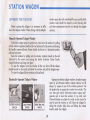
STATION WAGON
window open, the cowl vents should he open and the front
window vents should be closed to avoid drawing dust
and other contaminants into the car through the tailgate
opening.
LOWERING THE TAILGATE
Before opening the tailgate it is necessary to fully
lower the tailgate window. \-Vhen driving with the tailgate
Manually Operated Tailgate Window
Unlock the tailgate using the ignition key. then lower the window by pulling
out the window regulator handle at the end indicated by the arrows and turning
the handle counterclockwise. Rotate handle clockwise to a horizontal position
and snap into place.
Raise the window by pulling out the window regulator handle at the end
indicated by the arrows and turning the handle clockwise. Rotate handle
counterclockwise and snap into place.
To open the tailgate, lower the window all the way down, lift the release
handle located on the inside just below the window and pull th e tailgate open.
To close the tailgate lift into position and slam firmly.
Electrically Operated Tailgate Window
Operate the electric tailgate window (standard equipment on all three-seat station wagons-optional on all
others) by means of one of the switches pictured. Use
the ignition key to operate the window from outside. The
rear trim pad switch (three-seat station wagon only)
operates only to lower the window. If you wish, your
Chevrolet dealer can adjust the switch so that it may be
used to raise the window as well. Open the tailgate by
rolling the window fully down and lifting the release
handle inside the tailgate.
OUTSIDE TAILGATE
SWITCH
25
OPERATING THE FOLDING SEATS
The rear seats of your Station "Vagan may be quickly and easily converted into ca rgo space when needed.
Two-Seat Style Rear Seat
•
Release the locking lever on the right hand side of the
rear seatback.
•
Pull seatback forward and down.
•
To raise the seat, lean on the front edge of the seatback panel to remove tension from the filler panel, lift
up the filler panel at the location shown above, then
lift seat back up and rearward until it locks into place.
•
Three-Seat Style Seats
CENTER SEAT-Operate the center seat in the same
manner as the rear seat in the two-seat styles.
REAR SEAT-
Operate both sections of the optional two-section second seat in the same"manner,
26
•
•
Open the tail gate.
Grasp the rear of the seat cushion and rotate it over
and back, forming the rear of the cargo space.
•
Pull the seatback support link rearward and pull
the seatback rearward and down to complete the
Roor of the cargo space. Reverse the procedure to
raise the seat.
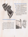
STATION WAGON CONCEALED LUGGAGE SPACE
•
•
•
STATION WAGON SPARE TIRE AND JACK STORAGE
The spare tire and jacking equipment are stowed
behind a removable panel in the right rear quarter panel.
The panel is held in place by means of a toggle latch.
After loosening the latch, the panel may be removed
from th e car. The tire is held in place by the large wing
nut and the jacking equipment is securely held b ehind
the tire.
27
Use the round key to lock and unlock the two-seat
station wagon luggage space lid lock.
In two seat styles th e two-piece -luggage space cover
may be folded toward t he front of th e car to expose
the rear half of the concealed luggage space or may
be folded completely forward to open the entire space
and allow you to carry higher, bulkier objects .
In three seat mod els, the stowage space is located
beneath the third seat and is completely concealed
when the seat is folded down .
SUPER-LIFf Am ADJUSTABLE
SHOCK ABSORBERS
Optional Super-Lift Air Adjustable Shock Absorbers
allow you to ride with the trunk or load space of your
car or station wagon fully loaded but with no annoying
sag or bumps. Air is added to the rear shocks as needed
through the air valve located as shown in the illustrations to the right. A minimum pressure of 10-15 psi. should
be maintained at all times. After the car is loaded, pressure
may be increased until the rear of the vehicle reaches the
desired riding height or to a maximum of 90 psi.
Automatic Level Control-Super-Lift Air Adjustable
Shock Absorbers equipped with Automatic Level Control
adjust automatically for changes in rear height requirements. No manual adjustments are necessary.
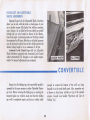
CONVERTIBLE
Except for the folding top, the convertible model is
operated in the same manner as other Chevrolet Passenger Cars. Before lowering the folding top or opening the
tempered glass rear window, make sure that the folding
top well is completely empty and that no articles bulky
enough to contact the bottom of the well are lying
beneath it on the trunk shelf panel. Also, remember not
to throw or drop heavy articles on top of the opened
window. Consult your booklet "Operation and Care of
Folding Top."
28
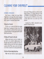
CLEANING YOUR CHEVROLET
maintain luster. \Vashing with water is all that is usually
required. However, C. M. Chrome Polish may be used
on CHROME or STAINLESS STEEL trim if necessary.
Use special care with ALUMINUM trim. Never use auto
or chrome polish, steam or any caustic soap to clean
aluminum.
EXTERIOR APPEARANCE
Your Chevrolet is finished with General Motors
"Magic-Mirror" acrylic lacquer. This is a finish of maximum
beauty which, in depth of color, gloss retention and durability is superior to conventional lacquer finishes.
A coating of wax, rubbed to a high polish, is recommended for all bright metal parts.
Washing Your Chevrolet
The best way to preserve the finish and maintain
original beauty of appearance is to keep it clean. Wash
the car in lukewarm or cold water. Never use strong soap
or chemical detergents. Cleaning agents should be quickly
Hushed from the surfaces.
Polishing and Waxing Your Chevrolet
Although acrylic paint on your car is durable, you
may wish to wax or polish for added protection. Your
Chevrolet Dealer offers many polishes and waxes now
available which have proven of real value in maintaining
a good paint finish. When using a tar and road oil remover, be certain it is safe for use on acrylic painted surfaces.
Protection of Exterior Bright Metal Parts
Bright metal parts should be cleaned regularly to
29
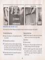
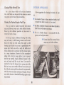
Cleaning White Sidewall Tires
INTERIOR APPEARANCE
Use a tire cleaner which will not harm aluminum
A few suggestions for cleaning the interior of your
car ...
trim. A stiff brush may be used with the cleaner to remove
road grime and dirt from white sidewall tires.
•
Use Leather Cleaner to clean imitation leather, vinyl
or coated trim fabric on seats or door panels.
•
Kar Kleen Upholstery Cleaner or Kar Kleen Upholstery
Spot Cleaner will remove most stains.
•
Use of a volatile cleaner is recommended for oil,
grease, and road grime stains.
Cleaning the Optional Impala Vinyl Top
The top should be washed frequently with neutral
soap suds, lukewarm water and a brush with soft bristles.
Rinse top with sufficient quantities of clear water to
remove an traces of soap .
If the top requires additional cleaning after using
soap and water, a mild foaming cleanser can be used.
Rinse the whole top with water; then apply a mild
foaming type cleanser on an area of approximately two
square feet. Scrub area with a small soft bristle hand
brush, adding water as necessary until the cleanser foams
to a soapy consistency. Remove the first accumulated
soilage with a cloth or sponge before it can be ground
into the top material. Apply additional cleanser to the
area and scrub until the top is clean. Care must be
exercised to keep the cleanser from running onto body
finish as it may cause streaks if allowed to run down and
dry. After the entire top has been cleaned, rins,e generously
with clear water to remove all traces of cleanser. Do not
use volatile cleaners or household bleaching agents on the
top material.
•
30
Caution should be exercised when
using soap and other solutions.
MAINTENANCE AND LUBRICATION
line, and if knocking continues, consult your Authorized
Chevrolet Dealer.
If you plan to operate your Chevrolet outside the
continental limits of the United States or Canada. there is
a possibility that the best fuels available are so low in
octane quality that excessive knocking and serious engine
trouble may result from their use. To minimize this possibility, write to Chevrolet Motor Division, General Motors
Corporation, Service Operations Department, Detroit,
Michigan 48202 giving: Your engine serial number (see
page 45), the compression ratio of your engine (see page
46) and the country or countries in which you plan to
travel. You will be furnished details of adjustments or
modifications which should be made to your engine by
your Chevrolet dealer prior to your deparhlre. After arriving in a foreign country, contact the nearest authorized
General Motors dealer for brand names of the best fuels
available and advice as to where they may be purchased.
In all cases excessive knocking should be avoided as
much as possible in order to prevent possible engine
damage. Operation of your car under conditions of continuous or excessive knocking constitutes misuse of the
engine for which the Chevrolet Division is not responsible
under the terms of the manufacturer's
ew Vehicle
Warranty.
GASOLINE AND ENGINE OIL
In the selection of gasoline and engine oil to be used,
it is best to consider the reputation of the refiner or
marketer. This is the best means of obtaining gasoline
and oil of high quality.
Gasoline
All Chevrolet 6 cylinder engines and V-8 engines with
two-barrel carburetors are uesigned to operate efficiently
on regular grade gasolines commonly sold in the United
States and Canada.
All Chevrolet higher performance V-8 engines are
designed to operate efficiently on premium grade gasolines commonly sold in the United States and Canada.
Use of regular grade gasolines in these higher perfonnance
V-8 engines may result in excessive knocking.
Since the octane quality of all regular grade or of all
premium grade gasolines is not the same and factors
such as altitude, terrain and air temperature affect operating efficiency, excessive knocking may result, even though
yOll are using the grade of gasoline recommended for
your engine. If excessive knocking occurs in your engine,
it may be necessary to use the next higher grade of gase-
31
OIL VISCOSITY AND QUALITY
Lowest Antici pated
Temperature During
The use of high quality oil of the correct viscos ity is
your best assurance of continued reliability and per~
fonnance from your engine.
It is recommended that you use an oil which, aecording to the label on the can is:
( 1) intended for service MS and
Multi-
in the Crankcase
Single
Viscosity
Oils
Viscosity
Oils
32° F.
SAE 20 or 20W
SAE 10W-30
0° F.
SAE 10W
SAE 10W-30
Below 0° F.
SAE 5W
SAE 5W-20
Time Oil Will be
NOTE 1: SAE 30 or 10W- 30 is recommended when most of
the driving is at high speeds and/or at temperatures above 90° F.
(2) passes car makers' tests or meets General Motors
Standard GM 4745-M.
NOTE 2 : SAE 5W-30 oils mar be used during periods when
tempe ratures of 32 and below are to be e xpected .
Oils conforming to these types contain detergent
additives.
OIL LEVEL
Regardless of the change interval being followed
check the oil level (with the engine hot) on the dipstick
regularly. Keep oil level between the FULL and ADD
marks, by adding oil when level is at or below the ADD
mark. It is not necessary to keep the level at the FULL
mark. DO NOT OVERFILL.
32
COOLING SYSTEM CARE
Air conditioned vehicles are equipped with a 15 lb. pressure type cap to provide added protection. The radiator
cap must be installed tightly.
, Your Chevrolet engine cooling system is equipped
with a 180 0 thermostat and is designed to operate on
permanent type (ethylene glycol) anti-freeze. Non-Permanent type coolants are not recommended since they
are not satisfactory for year around use and may not
effectively inhibit corrosion of the engine cooling system
when used with the quality of water found in some areas.
•
To remove the cap: tum a quarter of a tum to allow
the pressure in the cooling system to escape safely,
then turn the cap all the way off.
CAUTION: After a long hard drive or after driving during extremely hot weather, never attempt to remove
the radiator cap until the engine has been stopped
and allowed to cool for several minutes. Then carefully remove the cap as described above.
If the anti-freeze was installed at the factory or if it
meets the requirements of General Motors Standard GM
1899-M which contains adequate corrosion protection, it
may be left in the cooling system for 24 months or 24,000
miles, whichever occurs first.
To Completely drain .the cooling system:
Check the coolant level regularly. Level should be 1"
below top of filler neck when cold. Add water or permanent anti-freeze as required to maintain proper level.
Concentration of coolant should be to 0° F. or below to
insure sufficient corrosion protection.
•
All models-open drain cock on bottom of radiator.
•
6-Cyl. engine-remove drain plug on left rear side of
block.
•
Each fall have your Chevrolet dealer inspect the cooling system to insure that all connections are leakproof
and anti-freeze content will provide adequate protection
in cold weather.
8-Cyl. engine-remove drain plugs on each side of
block above oil pan.
BATTERY CARE
Check the fluid level in each cell of your battery
regularly. Keep filled with distilled water to the bottom
of the sput ring in the vent tube. DO NOT OVERFILL.
The standard radiator cap is a 13 lb . pressure type.
33
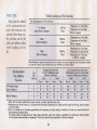
TIRE CARE
Keep your tires inflated
to the recommended pres·
sures. Over-inflati on can
adversely affect riding comfort, quietness and tire life
while under-inflation affects
vehicle handling and tire
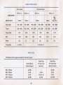
Vehicle Loading and Tire Selection
Full load capacity of the vehicle is :
All Models
1100 Ibs.
except Station Wagons
Total:
2 Seat
Station Wagons
1200 Ibs.
3 Seat
Station Wagons
1200 Ibs.
life.
Total:
Total:
3 Passenge rs in Front Seat
3 Passengers in Rear Seat
200 Ibs. Luggage
3 Passengers in Front Seat
3 Passengers in Rear Seat
300 Ibs. Luggage
3 Passengers in Front Seat
3 Passengers in Second Seat
2 Passengers in Third Seat
or 300 I bs. Luggage
Manufacturer's original equipment 4-ply rating tires are designed and thoroughly tested
to meet all normal requirements of your vehic le as outlined above.
Recommended
Tire InRation
Pressures
Ti re
Ply
Rating
All Models Except
Station Wagons
Station Wagons
-After car has been parked for 3 hours or more, or driven less than one mile .
• -Pressures can rise as much as 7 pounds above cold figures depending on loads carried , length of driving, and car speed
prior to checks.
@Front tire loads do not increase appreciab ly with passenger or cargo loading, therefore, the a bove is recommended for
best steering characterist ics.
For continuous full load service or heavy duty operation, eight ply rated or oversized t ire options are recommended
at the above recommended tire pressures. Their use is particu larly applicable to Station Wagons .
34
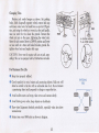
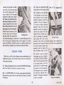
Changing Tires
Position jack under bumper as shown. Set parking
brake, block diagonally opposite wheel, remove hub cap
and loosen wheel nuts. Set small lever on jack to UP position, and using the wheel nut wrench as the jack handle,
raise car until the tire clears the ground. Remove the
wheel and put on the spare, tightening the wheel nuts.
Move th e jack control lever to DOWN position and lower
car one notch at a time until wheel touches ground. Retighten wheel nuts and replace hub caps.
2"-All OTHER MODelS
CAUTION: Never TUn. the en.gine with car on jack, especially if the car is equipped with a Positraction rear axle.
For Maximum Tire Life
•
Keep tires properly inflated.
•
Check regularly for cuts, bruises and puncturing objects. Nails etc. will
often be carried in the tire with no noticeable loss of air. Do not remove
a puncturing object until prepa red to change or repair the tire.
•
Avoid sudden starts and stops; take curves and corners slowly.
•
Avoid driving over curbs, sharp objects or chuckholes.
•
Have wheel alignment checked periodically, especially when tires show
unusual wear.
•
Rotate tires every 6000 miles as shown in diagram.
35
SWITCHING
TI RES
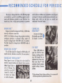
RECOMMENDED SCHEDULE FOR PERIODIC
The time or mileage intervals on the following pages
are intended as a guide for establishing regular maintenance and lubrication periods for your Chevrolet. Sustained heavy duty or high speed operations or operation
under adverse conditions may necessitate more frequent
servicing. To determine specific recommendations for conditions under which yOll use your car, consult your
Authorized Chevrolet Dealer.
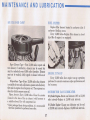
ENGINE OIL ':'
CRANKCASE
BREATHER *
Engine oil should be changed at 60 day or 6,000 mile
intervals, whichever occurs first.
NOTE: For Vehicles in heavy duty operation involving
continuolls start-stop or prolonged idling, engine oil
should be changed after 2500-3000 miles of operation.
The filter should be changed after 5000-6000 miles of
At every oil change •
the breather cap should
be cleaned in solvent.
operation.
FAN BELT
ENGINE OIL FILTER *
Every 6,000 miles inspect fan belt for wear,
fraying, cracking and tension. Belt should be retightened only when it deflects more than %" with
moderate thumb pressure
applied midway between
pulleys.
The oil filter should be changed at 6,000 miles or 6
month intervals, whichever occurs first. (See note above.)
CRANKCASE VENTILATION '
Valve Type-At every oil change the valve should be
tested for proper function and replaced when necessary.
Orifice Type-Check at
every oil change. Use
suitable size drill
(turned by hand) to
to remove any sludge
or carbon fonnation.
"Under prolonged dusty driving conditions, it is recommended
that these operations be perfonnedmore often.
36
MA IN TEN A NCE AND LUBRICATION
AIR CLEANEH CAHE*
FUEL FILTER
Replace filter element located in carburetor inlet if
carburetor flooding occurs.
Every 12,000 miles-Replace filter element in bowltype filter if engine is so equipped.
Paper Element Type - First 12,000 miles, inspect and
test element; if satisfactory, elemen t may b e reused but
must be rechecked every 6,000 miles thereafter. Element
must not be washed, oiled, tapped or cleaned with an air
hose.
Polyurethane Type-Every 12,000 miles clean element
in suitable solvent such as Kerosene, squeeze out all solvent,
then soak in engi ne oil and squeeze out. Then squeeze in a
clean dry cloth to remove excess oil.
Flame Arrestor-Every 12,000 miles-Clean the arrestor
ENGINE TUNE-UP
Every 12,000 miles have engine tune-up operations
pe rformed to maintain maximum engine perfonnance and
fuel economy.
DISTRIBUTOR CAM LUBRICATOR
6 Cylinder Engine-Rotate cam lubricator 180 0 at 12,000
mile intervals-Replace at 24,000 mile intervals.
(1ocated in the base of the air cleaner) with kerosene or
<l suitable solvent. Dry with compressed air.
*Under prolonged dusty driving conditions, it is recommended
that these operations be performed more often.
8 Cylinder Engine-Change cam lubricator end for end
at 12,000 mile intervals-Replace at 24,000 mile intervals.
37
BATTERY
Every 6,000 miles- Clean terminals and oil felt
amount of Automatic Transmission Fluid Type "A" bear-
washer.
suffix letter "A". Recheck fluid level on dipstick and again
BRAKES
add a small amount of fluid if needed to bring level to
full mark. DO NOT OVERFILL .
ing the mark AQ-A TF followed by a number and the
Inspect brake linings periodically. Frequency of
inspection will depend on traffic, terrain and the driving
habits of the driver.
Lubricate Powerglide shift linkage at frame and
transm ission with water resistant EP Chassis Lubricant.
Every 12,000 miles (more frequently*, depending on
severity of service, if vehicle is used to pull trailers, carry
fun loads during high ambient temperatures, operate in
mountainous terrain or operate under other severe conditions)-Remove fluid from the transmission sump and
add two (2) quarts* of fresh Ruid. Operate transmission
through all ranges and check Ruid level as described
above .
Master Cylinder
Every 6,000 mi les-Check fluid level and maintain
~"
below filler opening with GM Hydraulic Brake Fluid,
Supreme No. II.
Parking Brake P ulley, Cables and Linkage
Every 6,000 Miles-Apply water resistant EP Chassis
Lubricant to parking brake cable at cable guides and at
all operating links and levers.
REAR AXLE
Standard
Every 6,000 Miles-Check and keep filled to level of
filler plug hole with SAE 80 or SAE 80-90 Multi-purpose
TRANSMISSION
3-Speed, Overdrive and 4-Speed
Every 6,000 miles-Check at operating temperature
Gear Lubricant meeting requirements of U. S. Ordnance
and fill as necessary to level of filler plug hole with
SAE 80 or SAE 80-90 Multi-purpose Gear Lub ricant
Spec. MIL-L-2105-B.
meeting requirements of U.S. Ordnance Spec. MIL-L-
Positraction
2105-B.
Power glide
Every 6,000 miles- Check fluid level on dipstick with
Same as standard axle but use only the special positraction lubricant available from your Chevrolet Dealer.
·Except if vehicle is equipped with transmission provided in
heavy duty service options. If so equipped, drain converter
and sump every 12,000 miles and add approximately nine
(9) quarts of fresh fluid.
engine id ling. selector lever in neutral position, parking
brake set anq transmission at operating temperature. If
fluid level is below full mark on dipstick, add small
38
FRONT SUSPENSION
Every 6,000 miles or 6 months-lubricate 4 fittings with
watet' resistant EP Chassis Lubricant.
Ban joints should not be lubricated unless their temperature is 10° F . or higher. During colder weather, they
should be al10wed to warm up as necessary before lubrication.
cover attaching screws.
2. Inject water resistant EP Chassis Lubricant into the
forward cover attaching screw hole until lubricant
begins to come out of the outboard screw hole.
3. Replace both cover attaching screws.
POWER STEERING PUMP
Every 6,000 miles or 6 months-check level in pump
reservoir. Fill pump reservoir as required with C.M.
Power Steering Fluid or, if this is not available, Automatic Transmission fluid "Type A" with AQ-ATF-A mark.
Oil should be at operating temperature and wheels in
straight ahead position when checking or filling operation is performed to ensure against overfilling.
FRONT WHEEL BEARINGS
Clean, repack with a high melting point wheel bearing lubricant and adjust whenever the brake drums are
removed.
CLUTCH CROSS·SHAFT
Every 36.000 miles or sooner if necessary, remove the
plug, install a lubrication fitting and lubricate with water
resistant EP Chassis Lube.
AIR CONDITIONING
After the first 6000 miles-have your Chevrolet Dealer
check the tightness of all hose clamp connections.
Every 6,000 miles-check sight glass under the hood
after the system has been in operation several minutes.
Sight glass should be clear but may, during milder
weather, show traces of bubbles. Foam or dirt indicate a
leak which should be corrected immediately by your
Chevrolet Dealer.
Every week-during winter months-run the system
for five minutes to insure proper lubrication of the seals
and moving parts.
STEERL"IG LINKAGE
Every 6,000 miles or 6 months-lubricate fitting at
each tie rod end (4 fittings) with water resistant EP Chassis Lubricant.
STEERING GEAR
Every 36,000 miles-check steering gear lubricant
level in the following manner:
1. Remove the forward and the outboard steering gear
39
_ _ TRAILERS and their EFFECT on CAR OPERATION
by misuse of the vehicle with trailer loads, such part or
component will not be covered by the manufacture{s
wan-anty.
Chevrolet passenger cars are designed pdmarily for
passenger conveyance. However, it is well known that
many owners do use their Chevrolet to pull trailers, and
when available trailer hauling options have been used, the
owners have experienced very satisfactory service.
The size of and equipment for trailers, including such
items as hitches and safety chains, brakes, lights, power.
weight ratios and over-all length, are generally subject
to safety regulations in all states, and it is the responsibility of the user to make certain that he is in fun compliance with the regulations of the states in which he
plans to operate with a trailer and of the Interstate Commerce Commission, if applicable, before doing so. FUlther,
when operating a car with a b-ailer attached, the driver
must realize that the performance, steering characteristics,
and braking distance of his car have been altered, and
that he must exercise greater caution to safely handle his
car and trailer.
When a trai ler is attached to a car, the car becomes
not only a load.carrying vehicle, but a loadwpulling vehicle. The demands of th is type of operation an:! very difFerent from those for which the automobile is primarily
designed and may p resent problems, such as spring and
tire loading, braking, cooling, Jighting, and steering. However, careful driving practices and the use of factoryrecommended options win better satisfy the requirements
of trailer hauling.
If in the opinion of the manufacturer a part or component of a motor vehicle has been adversely affected
40
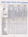
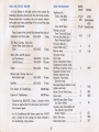
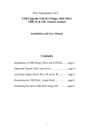
MINOR TROUBLE SHOOTING GUIDE
FUEL SYSTEM AND ENGINE
If your car acts
in the following
manner:
~
,
0
0>
~
,
•• "0;,
...
Check here in sequence
shown for possible causes.
'"
.c•
U
0
On the following pages, see paragraph:
Information on page
CAR WILL NOT START:
Engine Will Turn Over
Engine Will Not Turn Over
CAR WILL START -BUT :
Only After Repeated Tries
Stalls in a Few Seconds
St,IIs When Hot
Idles Rough
Engine Overheats
"Oil" Indicator Ught Comes On
"Gen" Ind icator light Comes On
,•"
0
A
"0
•,"
""
0
m
"0
0
" •C '".c0
0.0
," c."
•E 0
"•" "f
-,
,• U
0.0
0
,"
:c
"•0 >-0. "0 < E0
"0 E 00 .!! ,
u: W ~~ :!! <
a 0 a-c-o E DE
~
~
~
,~
~
~
~
....
."
~
~
"C
-• °
0
O>u
"•C
0;
>
0
C~
'c'i
~
0
C
0
:~
C
..J "
0
4
0>0
0
.c
" ;;:"
0"
:;;1:
U
o
c ._
:3~
.2 (1)
~c
~ o
E·o~
,i!E
0
:;-
L
E
F
00
". '"
~ .-
i5
_U
C~
~U
:!::c
.0>
~ .-
~~
~::;
'"0;
F
"0.
~
1
,
>C
C .;:
"0
co ~
"c ~" .~
c .~
C
"
•
~~
U
"0
o~
~.
~-
U
.t:
•
0
K
00>
~o
."
c .
.-~
- 0
•C
"
0
.U
0"
c ·CO
OC
O.!!
"0
0"
1::"
~c
al°
C;a:
8..J
(;)~
G
G
J
H
.
'!:!0
"C
00
QJ '';;
-u
Wo
c. C
EC
~o
cO
I
43
6
2
0
~
".
" C ", "
"'" !lc
Co
6-7
3
CODLING SYSTEM
oc
..J
~
0..
-"
">0
0
t. ,11,32 37
8
1
•0
ELECTRICAL SYSTEM
2
3
"
,,'
c"
CO
"
•
~$
oE
.co
..J
~
:;; ....
"':
.,!;
Uo>
"C "
", E .c,
•C
0;
0
>
0
0
~
C~
~C
",. -
0
0
~
"0 ~"0
•"C .~
~
~
~
".'""
0_
.ca:
~2
o~
U::C
• a:" :.;:a:
""
~
"G
M
9
33
N
.
C ·~
0"
0<
~iU
,,~
0",
0"
,,~
.co.
"'E
c"
m-C :':11)
"c
~c
-0
0 .-
c •
~f-
0
o.c
0>,
"0 ,
0 0
8'" ~'"
P
33
5
7
5
4
1
2
1
3
1
1
2
3
2
4
3
1
2
3
1
3
"'See Your AuthorIZed Chevrolet Dealer
41
2
4
1
4
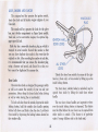
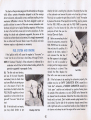
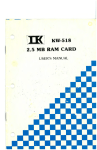
whether the fuel is reaching the carburetor. Disconnect the fuel line
at the carburetor and remove the center wire from the coil tower.
Place a jar or cup under the open line and briefly "cro nk" the engine
by means of the starter. If fuel spurts from the fitting, you moy assume
that the FUel LINES are clear and the FUEL PUMP is operating
properly. If no fuel leaves the lin e, either the fuel lines or fuel
pump are at fault. See you r Authorized Chevrolet Dealer.
(C) Before reconnecting the fuel
line to the carburetor, remove the
FUel FILTER from the carburetor
inlet and check its cond ition . If it
appears to be clean, replace it
and reconnect the fuel line. If
the £lIter appears to be plugged,
clean it as well as possible by
scraping out the foreign material
and cleaning in a so/vent. Then
Fuel Filler
reinstall the filter. Replace the
filter wi th a new one as soon as possible.
The chart on the previous page, and the information on the pages
which follow, conta ins information designed to aid the average
driver to discover, and possibly correct, conditions resulting in minor
mechanical difficulties in his car. The chart, designed to point out
p ossible solut ions to severa l of the most common automotive malfunctions and point out a logical checking sequence, will lead step
by step to the most like ly causes and corrective procedures. If, after
making the checks and adjustments suggested, the source of the
trouble has not been found and corrected, it is strongly recommended
that an Authorized Chevrolet Dealer inspect the vehicle and make
whatever repairs or adjustments are necessary.
FUEL SYSTEM AND ENGINE
If the ignition switch will ca use the engine to "turn over" or
"crank" but the cor wi ll not start, check Steps A through D below.
NOTE: If Continual "flooding" of the carburetor is evidenced by a
carburetor wet with fuel or black exhaust smoke, perform the
operation suggested in paragraph D only.
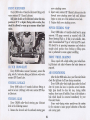
(A) The first and most obvious,
and one of the most frequently
overlooked, items to check when
you have difficulty in starting your
cor is the amount of fuel in the
tank . Make it a habit to check the
FUEL GAUGE regularly and most
especially at a time when the engine will " turn over" but will not
start.
fBI If the fuel tonk is not empty,
you may check further to see
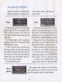
Checkin9' Fuel Flow
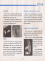
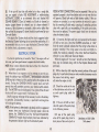
(0) If the fue l seems to be reaching the carburetor properly, the
problem may be: an EMPTY CARBURETOR BOWL caused by a
" stuck shut " carburetor; a flOODED CARBURETOR caused by a
"stuck open" condition and evidenced by gasoline flowing down
the outside of the carburetor; or a stuck CHOKE va lve. Remove the
air cleaner from the carburetor. Check that the choke valve moves
free ly and is not stuck. (Don't mistake normal spring tension for a
stuck valve.) Top the side of the carburetor sharply several times
with a light too/ such as a screwdriver handle or pliers. Replace the
air cleaner and attempt to start the engine in the normal manner.
42
(El If the car will start but sta ll s when hot or has a rough idle,
you can suspect a faulty IDLE ADJUSTMENT, a malfunctioning
AUTOMATIC CHOKE or on extremely dirty and blocked AIR
CLEANER ELEMENT. Clean [oil wetted or oil bath air cleaner) or
replace (pape r element ai r cleaner) your air cleaner element if
necessary. Idle adjustment or automatic choke service (other than
that outlined in paragraph D above) should be perfo rmed by you r
Chevro let Dealer.
If the above fuel System checks and the checks suggested under
the Electrical System following do not correct the malfunction, it is
recommended that you turn to your Authorized Chevrolet Dea ler
for further checks, adjustments or repairs.
POOR BATTERY CONNECTIONS may be suspected if the cor has
operated properly a short time before and now not even the horn
will operate. Check both ends of both battery cables. If the connections are corroded, a car may sometimes be restored to opera·
tion by removing all cable ends, scraping all contacting surfaces
clean with a pen knife, and reassembling. If the cables are broken,
they must be replaced. The power supply should now be restored
unless the battery is dead.
If, however, the lights and horn work p roperly but the starter
will sti ll not turn over, check the STARTER connections. A "dick"
from the starter solenoid ind icates that the wiring to the starter is
properly installed. If the wiring seems to be clean and tightly installed, the trouble is probably in the starter itself and should be
referred to you r Authorized Chevrolet Dealer.
When the engine will "turn ove r" but will not start, the following
items may be checked along with the Fuel System Checks listed
previously.
(H)
ELECTRICAL SYSTEM
If, when the ignition key is turned to "Start", the engine wilJ not
turn over, you have good reason to suspect electrical trouble.
NOTE: Never remove Delcotron bat lead without first disconnect·
ing battery ground coble.
(F) When there is no response at all to attempts to start the car,
check the obvious-you , AUTOMATIC TRANSMISSION SElECTOR
LEVER must be in Neutral or Park position before the engine can be
storted. Turning the IGNITION SWITCH rapidly bock and forth
several times will sometimes correct a poor internal switch contact.
(G) The BATTERY may be discharged. If so, lights will be dim and
the horn will have a poor tone if it will blow at all.
Usually a garage recharge will be necessary to return the battery
to operation. Occasionally, however, a push start and long drive
will recharge the battery.
NOTE: If the battery is determined to be dead, and for no apparent
reason, have your Authorized Chevrolet Dealer check the
botf.,y, the GENERATOR and the VOLTAGE REGULATOR .
GENERATOR trouble should already have been indicoted by
the generator indicator fight on the instrument panel.
(I) With a clean dry cloth wipe the ceramic portions of the spa rk
p lu gs dry. In particularly damp or rainy weather dampness may be
the cause of not starting, especially when the engine is cold.
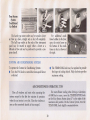
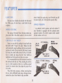
(J) Check the cables at the top
of the distributor and coil as well
as each spark plug coble for
tigh tness.
If the car wil l still not start,
check for spark at the spark plugs
in the following manner:
(K)
Pul l one of the spark plug
wires off its spark plug. Insert a
short piece of bore wire (such as
43
Distriburor and Coil Cables
fV-8 shown)
a bobby pin) between the r,ubber
cup at the end of the spark plug
wire and the tubular metal connector inside of it. If the spark
plug wire is wet or oily, wipe it
dry. Wrap a dry handkerchief or
facial tissue, folded several thicknesses, around the wire at least
three inches back from the end
and grasp the wire at this point,
Hold the bare wire about % inch
from the bare tip of the spark
Checking Spark
plug from which you removed the
wire. When the engine is "turned o .... er .. a spark should jump across
the % inch space, indicating ample current supp ly. If no spark
jumps, the difficulty is probably caused by a defecti ....e ignition part
and should be corrected by your Authorized Chevrolet Dealer.
(N)
Check the RADIATOR CORE. Cleon it if it is plugged with
bugs, leaves or other foreign material.
(0) Condition of the FAN BElT
is very important, not only for engine cooling but also for proper
generator operation. Check the
condition of the bel t, Replace it
if it is worn or frayed. Loosen the
generator bolts and move the
generator toward the engine to
remove and replace the belt.
Tighten the belt, whether new or
old, by loosening the generator
Fan Belt Tension
bolts, prying with a ba r on the
generator until the belt is tensioned properly, then retighten the
genera tor bolts. Proper belt tension is such that, when pressed hard
at a point midway between the
generator and fan pulleys, the
belt will deflect about % inch.
COOLING SYSTEM
(P) Another cause of engine
o .... erheating may be an inopera-
When the car will run but evidences serious overheating on the
temperature gauge in the instrument panel, there are se .... era l items
which may be checked,
tive COOLING SYSTEM THERMOSTAT. If the thermostat should foi l
in the closed position, it will not
permit water to circulate through
the system, In such an emergency
the thermostat may be remo .... ed
but should be replaced with a
properly functioning thermosta t
as soon as possible.
(L) Engine over,h eating will occur when the OIL LEVEl falls dangerously low, Check the oil le .... el as a matter of course.
(M) low WATER lEVEL will, of course, cause engine overheating.
Determine the cause of the low water level and have it corrected
if necessary.
44
Thermoslaf Installation
Litho in U.S.A.
SPECIFICATIONS
SERIAL AND UNIT NUMBERS
Thermostat .. .. ...... . ......•. .. . . ..•..
Radiato r Pressure Cap (with Air Cond.)
(all others) . ....... .
·With Air Cond itioning-odd 2 qt.
Car-Stamped on vehicle identification number plate attached
to left front body pillar.
Body-Stamped on plate attached to upper right corner of
cowl panel.
Engine-Stamped on boss on block.
S-Cylinder-On right front side of b lock.
6-Cylinder-On right side of block to rear of distributor.
BAHERY RATING
6 cyl. and 283 v-s Engines-12 .... olt. 54 plate. 44 omp/ hr
rati ng or. with Air Conditioning. 53 amp/hr rating. All 327
Engines-12 volt. 66 plate. 61 amp/hr ra ting . 409 EngineMechanica l lifters-12 .... olt. 66 plate, 61 amp/ hr ratingHydrau lic Ufte rs-12 .... olt, 66 plate, 70 amp/hr rating .
DIMENSIONS
Overall length (Station Wagons) ...... • . •..
(All other models) . . . . . . . . . . .
. . . •. • ..
Width .......... .. . . . . . . . . . . . . . . • . . . . . . .
Wheelbase .. . . .. ... .. . .• ......•. . . .. . . ..
213.3"
213.0"
79.6"
119.0"
TIRE INFORMATION
Type ........... .
....... _ ... .
All olher Mode ls
Crankcase (Refi ll)
230 L-6 .. . .......... .• . . ........ • ..
283 and 327 V-8 .................... .
409 V-8 ................ .. ......... .
When changing oi l filter element, odd additional
23.5 gal.
20 9 0 1.
4 qt.
4 qt.
4 qt.
1 qt.
12 qt.*
283
v·a
17 qt. '"
327 v·a
{250 hpj
16 qt. *
327 v·a
{300 hpj
18 qt.
409
22
7 .35 x 14
7.75 x 14
8.25x 14
7.75 x 14
8.25 x 14
TURN SIGNAL FLASHER,
Type ..... . ................ . . .
Cooli ng System
230 L-6
. .......... • .. . .... Tubeless
Size:
Regu lar Production except
Station Wagons and Convertible
Con .... ertible .................. . .. . ... .
Station Wagons
All 327 engine equipped .... ehicles
(except Station Wagons) .....
All 409 engine equipped vehicles
CAPACITIES
Gasoline Tank
Station Wagon
180'
15 lb.
13 lb.
Capacity-Impala (except Sta. Wag.)
and Super Sport ... . .
Bel Air, Biscayne and all
Station Wagons ...... . . . ...
v·a
qt. *
45
Series
3-lamp (Ll)
2-lamp Ill)
ENGINE SPECIFICATIONS
6 Cyl. Engine
230 Cu. In.
8 Cylinder Engine
283 Cu . In .
327 Cu . In .
409 Cu. In.
CARBURETOR
4 Bbl.
with
ENGINE DATA
1 Barrel
2 Barrel
4 Barrel
4 Barrel
Spec . Cam
4800
250 @ 44Q0
300 @ 5000
340 @ 5000
400 @ 5800
220 @ 1600
285 @ 2400
350 @ 28OO
350 @ 3200
420 @ 32OO
425 @ 3600
Compo Ratio
8.5,'
9.25,1
'0.5"
,0.5 "
,0.0"
11.0,'
Bore
3.875
3.875
4.00
4 .00
4.313
4.313
Stroke
3.25
3.0
3.25
3.25
3.50
3.50
Horse power
140
Torque
Firing Order
@
4400
195
@
1-5-3-6-2-4
1-8-4-3-6-5-7-2
SPARK PLUGS
The following 14mm plugs are provided for Chevrolet engines.
(For City-Type
Colder Plug
(For Continuous
Operation)
Heavy Duty Oper.)
-
AC-44N
AC-44
AC-43
AC-C42N
Hotter Plug
Normal Service
(Original Equipt.)
230 L-6 Engine
283 V-S Engine
327 V-S Engines
409 V-S Engines
AC-46N
AC-4S
AC-44
AC-43N
46
AC-46
AC-4S or 46
AC-44N
FUSES AND CIRCUIT BREAKER,
BULB SPECIFICATIONS
A Circuit Breaker in the light control switch protects the
headlamp and parking lamp circuits, thus eliminating one fuse.
Where current load is too heavy, the circuit breaker intermit·
lentry opens and closes, protecting the circuit until the couse
is found and e limina ted.
Headlomp Unit
Outer-High Beam
low Beam
3AG/AGe-
15 amp.
3AG/AGe3AG/AGe-
7% amp.
3AG/AGe-
10 amp.
Backup light, Parking light ' and
Broke Signal Light . . . . . . . .. 3AG/ AGC
10 amp.
Spotlight . .. . ..... . ........ 3AG/ AGe-
15 amp.
Radio (AM or AM·FM, Manual
and Push Button}
[AM-FM S,.,oo) ........ .
Heater
..... " •••.... . ....
2%
Bock-up lamp . . . . . . . . . .
Instrument lamps
Clock lamp
Glove Comportment lamps
Temperature Indicator lamp
Oil Pressure Indicator lamp
Generator Indicator lamp
Hi-Beam Indi cator lamp
Automatic Transmission
Quadrant lamp
Directional Signal Indicator lamp
Ignition lock lamp
Heater Control Panel lamp .....
Dome lamp .... .. . ... . .... ..
Side Roil lamp (Sport Coupe
and Sport Sedan) . . . . ... . ..
Courtesy lamp (Convertible) and
Rear Quarter lamp (3-Seat
Station Wogan) . ...... .. . . .
Radio Dial lamp . . . . . . . . . . . . .
Brake Alarm lamp ....• .. .... •
amp.
Four Season Air Conditioning ..
SAE-30 amp.
Custom Air Conditioning ..... .
SAE-20 amp.
55W
Inner-High Beam .. . ....... . 37'1,W
Toil, Stop, Courtesy, Glove Box,
license Plate, Dome Lights and
............... .
37V,W
Parking lamp and
}
Front Di rectional Signal
Toil and Stop lamps and
. . ... .
Rear Directional Signal
Toil l amp (Bel Air) }
li cense Plate lamp ..... . ..... .
Fuses, located in the Junction Siock beneath the dash ore:
Instrument and Clock lights .... JAG/ AGC~
3 amp.
Clock
Candlepower
I
O ve rdrive Fuse, 3AG/ AGC- 15 amp., is located in wiring
harness on engine side of the dash panel just forward of
the instrume nt panel.
An Air Conditioning high blower speed fuse, SAE-JO
amp. is located in wire running from starter solenoid to
Air Conditioning wiring harness.
47
4-32
Number
4002
(Sealed Beam)
4001
(Sealed Beam)
1157
4
67
32
1156
2
1895
I
1445
2
.
.
15
1895
1004
.
6
90
.
.
.
6
2
2
631
1893
257
INDEX
Air Conditioning ....... .
.18
Air Vents ............. . ..... .
Ammeter (Super Sport).
.. 22
. ... . . 11
Ash Tray ...... .
. .. 22
Battery Care .. .
. ... 33
Brakes ....................•...
Cleaning ......... ......
. .... 14
...29
Ignition Switch ..... . ..... .
Sp ec ification s..... .....
Station Wagon.. ... ..
Super-Lift Shock Absorbers.
Lubrication. .... .......... .
Fuel Gauge .. . . .
Gas Cap ............... .
. ..... 41
.32 , 36
.. 12
Oil Pressure Gauge (Super Sport) ..... 11
.. ...... 28
Oil Pressure Indicator Light. .......... 9
. ... 33
Headlight Beam Switch ..... .
. ...... 31,36
Maintenance and Lubrication .... ... 31,36
Oil and Filter ....... ..
Cooling System Care....
..... 13
...... .. .. ...... 8
.... 24
Generator Indicator light. ....••...... 9
. ..... 45
Stee ring, Power.......
.. .. 12
Op erati ng In structions ..... .
Other Features ........ .
Park i ng Brake Indicator Lig ht.
. ... 4
. .. .. .. 22
... 10
Power Windows and Steering ...... . ... 23
Pushing to Start ...... .
7
. .... 23
Ta chometer ..
Ta ilgate ..
. .10
Temperatu re Gauge (Super Sport) . .... 11
Temp erature Li ghts.
. ............ 9
Tire Care .... .. ... .
Towing ........ ...... . .... .
Trailers .... .
Trans miss io n, Manual.
Overdrive ..
Powergl ide ......... .
Glove Box.
.... . 23
Radios .. . ............ .
... . 16
Heater ......
..... 17
Rear Compartment.
.... 24
Vacuum Gauge (Super Sport).
Headlight Beam Indicator Light. ....... 10
Seats ........ .
Seat Belts ..
. .. 20,26,27
. ..... 23
48
. ....... 28
. .............. 25
Turn Signal Lever ........... .
Hood Release .. .. . . ........... .... ..... 24
. .. . .... 18
. .... 25-27
Light Switch.. ...
Comfort-Tilt Steering Wheel.
Convertible.. .... .........
. .4,21
Light ing System Troub le Checks ....... 13
Minor Troubl e Shooting.
Controls. . . . .. .. . . . . . .
Speedometer and Odom eter.
Keys, Doors and Locks.
Clock ....... ...... ....................... 22
. .. .22
..... 4
Instruments .............. .. ............. 8
Windows, Power... .....
. .. 34, 35
. .. 7
... . 40
. .5
. ... 5
6
.13
.10
. ........ 23
Windshield Wiper and Washer ......... 15
SERVICE LITERATURE ~ CHEVROLET CARS and TRUCKS
The following Chevrolet publications covering the operation and servicing of Chevrolet Vehicles can be purchased
by filling out the order form and mailing it with check or money.order payable to Helm Inc.
ST-56
5T-57
5T-58
1965 Shop Manuals
Service Manual
Price each $4.25
Applies to Chevrolet, Chevy II and Chevelle. Includes on-the-car adjustments, Maintenance cnd
Overhaul of minor ossem bles and specifications.
(e.g. windshie ld washers, distributor, etc. Will
hondle most owner's requirements.)
Overhaul Manual
Price each $3.50
Applies to Chevrolet, Chevy II and Chevelle. Includes basic off-the-cor overhaul of major assemblies (e.g. engine, transmission, axle, etc. )
Body Service Manual
Price each $3.50
Includes all information for Chevrolet, Chevelle,
Chevy \I and Corvoir car bodies.
Available Manuals
FORM NO.
CHEVROLET
SHOP
MANUAL
R5-34
R5-57
R5-58
R5-60
R5-62
5 & M-15
5 & M-32
5T-6
5T-18
5T-30
H-l0
YEAR
PRICE EA..
(1949-54)
(1955)
(1956*)
(1957)
(1958)
(1959-60*)
(1961)
(1962*)
(1963**)
$4.00
4.00
3.00
4.00
4.00
3.75
4.75
3.00
3.75
3.50
6.00
(1964 suppl emen t)
(1964 w/'61 for wnp lele coo.er.)
YEAR
FORM NO.
CHEVY II
SHOP
MANUAL
CORVAIR Ie
CORVAIR 95
SHOP
MANUAL
5T-7
5T-19
5T-31
H-30
5 & M-21
5 & M-34
5T-8
5T-20
5T-33
H-35
5T-59
PRICE EA.
(1962)
(1963* )
$4.50
2.25
(1964 suppl ement )
2.00
(1964 w/ '62 for u"",Lele n nr.) 5.00
(1960)
(1961 )
(1962*)
(1963**)
(1964
sunl, m.n!)
(1964 w/'61
(1965)
CHEVELLE
SHOP
MANUAL
5T-32
(1964)
5T-21
5T-34
H-40
5T-60
H-45
(1963)
CORVETTE
SHOP
MANUAL
(1964
4.75
sunl l ment)
(1964 w/ '63
(1965
for compl,te cover.)
3.75
4.25
2.75
2.75
2.50
5.00
4.25
for comp lete cover. )
suppl ement)
(1965 w/'63
for complete tover.)
4.50
2.00
5.00
2.00
5.00
*Previous year model manual must be ordered with this supplement to obtain complete coverage.
**J96J model manual must be ordered with supplement to
obtain complete coverage.
YEAR
FORM NO.
RS-56
RS-54
S & M-56
RS-61
RS-63
TRUCK
SHOP
MANUAL
S & M-16
S & M-22
ST-9
PRICE EA.
(1954)
$3.75
3.25
(1955)
3.00
3 .25
(1956 *)
(1957)
(1958)
3.50
1.50
(1959* )
(1960)
3.75
4.00
(1960-62* )
ST-22
(1963)
ST-35
H-15
ST-61
(1964 su ppl ement)
(1964 w/'63 for lo mp •• h tover.)
(1965 suppl ement )
(1965 w/ '63 Inr , o mpl ll ~ mer.)
H-20
AVAILABLE CHEVROLET SHOP MANUALS
PRIOR TO 1949
The shop manuals listed below are out of print. The information
contained in these shop manuals has been prepared on microfilm.
We are able to produce a 35 mm positive film strip from this
mic rofilm. The film can be viewed through any type of fi lm viewer
adaptable to 35 mm.
4.75
2.75
5.50
2.75
5.50
A V AILABLE FILMS
1919 Chevrolet
Car Shop Manual
5T-36
CHEVY VAN
SHOP
MANUAL
H-25
(1964-65
supp le ment)
(1964-65 w/'63 Truck
3.00
5.75
1923 through 1948
Chevrolet Shop Manuals
for tomplele coveTlI" l
1934 through 1952
Truck Shop Manuals
OWNER GUIDES
Chevrolet, Chevy II, Corvair, Corvair 95 and Chevelle .30 each
Truck and Chevy Van
.40 each
Corvette
.60 each
Convertible Top booklets
.25 each
Please specify model year and vehicle when ordering.
Price $5.00 Each
(For 1953 Truck Shop Manual,
Order 1952.)
Please allow 30 days for order to be filled.
*Previous year model manual must be ordered with this supplement to obtain complete coverage.
NOTE: PLEASE FILL ORDER FORM IN COMPLETELY, CUT HERE AND MAIL TO,
HELM Incorporated
Post Office Box 7706
Detroit, Michigan 48207
please mail Check or Money Order (NO STAMPS) for the publications you have ordered
on form.
NOTE: Purchasers outside Domestic U.S.A. must add 30e to each publication for mailing
expense. Funds MUST be payahle in U. S. Currency.
All orders will be moiled within 10 days of receipt of order. Please allow approximately
30 days for poslal service.
YEAR
FORM NO.
QUANTITY
PRICE EA.
TOTAL
Remarks _______________________________________________________________
Total Order_ _ _ __
Michigan Purchasers odd
(of both columns)
Michigan Sales Tax.__________
4% Sofes Tax
Grand TOlol _ _ _ __
Prices subjed to change after July J, 1965
PLEASE COMPLETE SHIPPING LABEL BELOW
SIGNA.TURE OF PURCHASER
STREET ADDRESS
.-
CITY, POSTAL ZONE, STATE
,
IMPORTANT Th"1$ .U your $h'IppmQ r0 b I
1ml/", HELM Inc.
PI eOI' pnn
" cIeor Iy
Chevrolet Manual Distribution Department
POST OFFICE BOX 7706
1cl'
•
DETROIT, MICHIGAN 4B207
(NAME)
(STREET ADDRESS)
(CITY, ZONE, STATE)
RETURN REQUESTED
CHEVROLET OWNER PROTECTION PLAN
The Chevrolet Motor Division considers it a most important obligation to offer
each owner a recommended maintenance service guide which will relieve him
of any anxiety and insure that his vehicle is regularly inspected and maintained .
Your Chevrolet dealer has presented you with a Chevrolet Owner Protection
Plan Booklet. The recommended Maintenance and Lubrication Service items in
this Plan Booklet have been worked out by Chevrolet service personnel and
cover items which are the owners responsibility to have checked, inspected,
adjusted and lubricated at recommended time or mileage intervals.
If the services are carried out at the prescribed time or mileage intervals,
wear and owner expense will be kept to a minimum. Additional services may
become necessary as mileage accrues, however, the regular visit that you make
to your Chevrolet dealer in following this Plan will point out desirable services
as they become necessary.
In the event warranty repa ir is required on your Chevrolet, the Chevrolet
Protect-a-Plate affixed to the back cover of your Protection Plan Booklet will
assist in identifying you a nd your Chevrolet to your Chevrolet dealer.