1
REVISION 0
MAR. 1999
QY8-1356-000
COPYRIGHT 1999 CANON INC. CANON BJC-8500 0399 AB 0.30-0 PRINTED IN JAPAN (IMPRIME AU JAPON)
0399 AB 0.30-0
Target Readers
This manual is published by Canon Inc. for qualified persons and contains the necessary technical
information for technical theory, installation, maintenance, and repair of products. This manual covers
all localities where the products are sold. For this reason, it may contain information that does not
apply to your locality.
Revisions
This manual may include technical inaccuracies or typographical errors due to improvements or
changes in the products. When amendments are made to the content of this manual, Canon will issue
technical information as the need arises. In the event of major alterations to the content of this manual
over a long or short period, Canon will publish a revised version of the manual.
The following paragraph does not apply to any countries where such provisions are
inconsistent with the local law.
Trademarks
The product names and company names appearing in this manual are the registered trademarks or
trademarks of the individual companies.
Copyright
This manual is copyrighted and all rights reserved. Under the copyright laws, this manual may not be
copied, reproduced, or translated into other languages, in whole or in part, without the express written
consent of Canon Inc. except in the case of internal business use.
Copyright 1999 by Canon Inc.
CANON INC.
BJ Products Quality Support Dept.
16-1, Shimonoge 3-chome, Takatsu-ku, Kawasaki, Kanagawa 213, Japan
This manual was produced on an Apple Macintosh Power Mac 7300/180 personal computer and Apple
LaserWriter II NTX-J laser beam printer; final pages were printed on Agfa SelectSet Avantra 25.
A YANO 640MO drive system NJ640MO with MITSUBISHI MO disk cartridge MR230M1 were used for
storing large volumes of page layout and graphic data for this manual.
All graphics were produced with MACROMEDIA FREEHAND 7.0J.
All documents and all page layouts were created with QuarkXPress 3.3J.
I. ABOUT THIS MANUAL
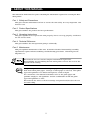
This manual is divided into five parts containing the information required for servicing the BJC8500 printer.
Part 1: Safety and Precautions
This part contains information on how to service the unit safely. It is very important, and
must be read.
Part 2: Product Specifications
This part outlines the product and its specifications.
Part 3: Operating Instructions
This part explains how to operate the unit properly, how to set it up properly, and how to
use the service mode.
Part 4: Technical Reference
This part outlines the unit operation giving a technically.
Part 5: Maintenance
This part explains maintenance of the unit. It includes details of disassembly/assembly,
adjustments required when assembling, troubleshooting procedures, and wiring/circuit
diagrams, etc.
This manual does not contain complete information required for
disassembling and assembling the BJC-8500 printer. Please also refer to the
separate Parts Catalog.
This printer prints various ink and plain paper ink optimizer (except in the
draft mode when plain paper, envelope or thick paper is selected). This plain
paper ink optimizer is an almost transparent, colorless liquid.
For convenience, this manual sometimes refers to the plain paper ink
optimizer simply as "ink optimizer" and the combination of ink and plain
paper ink optimizer as "ink."
This manual also refers to the BJ cartridge and print head (head) as the one
and same thing.
I
II. TABLE OF CONTENTS
Part 1: SAFETY AND PRECAUTIONS
Page
1- 1
1- 1
1- 2
1- 2
1- 3
1- 4
1- 5
1- 5
1- 5
1- 6
1- 7
1- 7
1- 7
1- 8
1- 8
1- 8
1- 9
1- 9
1- 9
1 -10
1 -10
1 -11
1 -12
1 -12
1 -13
1 -13
1 -14
1 -15
1 -16
1 -16
1 -16
1 -17
1. PERSONAL SAFETY PRECAUTIONS
1.1 Moving Sections of the Printer
1.2 Ink Stains
1.2.1 Ink path
1.2.2 Ink mist
1.3 Electrically Live Sections of the Printer
2. MACHINE PRECAUTIONS
2.1 Handling BJ Cartridges
2.1.1 Unpacking BJ cartridges
2.1.2 Protecting BJ cartridges
2.1.3 Turing the printer ON/OFF
2.1.4 When not using the printer
2.1.5 Ink electroconductivity
2.2 Handling the Ink Tanks
2.2.1 Unpacking the ink tanks
2.2.2 Protecting the ink tanks
2.3 Handling the Printer
2.3.1 Spurs
2.3.2 Encoder
2.3.3 Paper feed roller unit
2.3.4 Purge motor
2.3.5 Precautions to prevent damage from static electricity
2.3.6 Ink leakage/ink dry-up precautions
2.3.7 Precautions when carrying the printer
3. PRECAUTIONS FOR SERVICE
3.1 Precautions Concerning Memory Data
3.2 Special Settings
3.3 Precautions to Prevent Damage from Static Electricity
3.4 Precautions for Disassembly/Assembly
3.4.1 Disassembly prohibited parts
3.4.2 Precautions for disassembly/assembly
3.5 Self-diagnostic Functions
2- 1
2- 1
2- 2
2- 3
2- 3
2- 3
2- 4
2- 5
2- 6
2- 7
2- 7
2- 7
2- 8
2- 8
2 -11
2 -11
Part 2: PRODUCT SPECIFICATIONS
1. PRODUCT OUTLINE
1.1 Product Outline
1.2 Features
1.3 BJ Cartridges
1.3.1 Black BJ cartridge [BC-80]
1.3.2 Color BJ cartridge [BC-81]
1.3.3 Photo BJ cartridge [BC-82 Photo]
1.3.4 Relationship between BJ cartridges and printing mode
1.4 BJ Cartridge Container SB-80
1.5 Consumables
1.5.1 BJ cartridge
1.5.2 Ink tank
2. SPECIFICATIONS
2.1 General Specifications
2.2 Paper Specifications
2.2.1 Paper types
II
Page
2 -12
2 -13
2 -13
2 -19
2.2.2 Printing area
2.3 Interface Specifications
2.3.1 Parallel interface
2.3.2 Serial interface
Part 3: OPERATING INSTRUCTIONS
3- 1
3- 1
3- 3
3- 4
3- 4
3- 4
3- 5
3- 8
3- 9
3 -10
3 -10
3 -10
3 -11
3 -13
3 -15
3 -15
3 -16
3 -17
3 -17
3 -17
3 -18
3 -18
3 -19
3 -19
3 -21
3 -23
3 -23
3 -24
3 -25
3 -27
3 -27
3 -27
3 -28
3 -29
1. PRINTER SETUP
1.1 Unpacking
1.2 Installation Space
1.3 Installation Procedure
1.3.1 Connecting the interface cable
1.3.2 Connecting the power supply
1.3.3 Installing BJ cartridges
1.3.4 Replacing ink tanks
1.3.5 BJ cartridge container SB-80
1.4 Turning the Printer ON/OFF
1.4.1 Turning the printer on
1.4.2 Turning the printer off
1.5 Paper Settings
1.6 Names and Functions of Parts
2. TRANSPORTING THE PRINTER
2.1 Transporting the Printer
2.2 Capping Lock/Unlock
3. PRINTER SERVICING FUNCTIONS
3.1 Error Indications
3.1.1 Operator call
3.1.2 Service call
3.2 Warning Display
3.3 Function Settings
3.3.1 Maintenance settable items
3.3.2 Custom setting
3.4 Control Buttons
3.4.1 Cleaning the BJ cartridges
3.4.2 Service mode
3.5 Self Test Print (Nozzle Check Pattern)
3.6 EEPROM
3.6.1 Continued use of EEPROM memory data
3.6.2 Resetting the EEPROM
3.6.3 EEPROM list print
3.6.4 Destination setting
44444444444-
1. OVERVIEW
1.1 Printer Block Diagram
1.2 Initial Flowchart
1.3 Power OFF Operation Flow
1.4 Print Signal Flow
1.5 BJ Cartridge Drive
1.5.1 Printing drive control
2. FIRMWARE
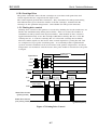
2.1 Interface
2.1.1 Nibble mode
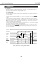
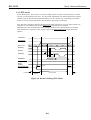
2.1.2 ECP mode
Part 4: TECHNICAL REFERENCE
1
1
2
5
6
7
7
8
8
8
9
III
Page
4 -10
4 -11
4 -11
4 -11
4 -11
4 -12
4 -14
4 -14
4 -14
4 -15
4 -15
4 -16
4 -17
4 -17
4 -18
4 -19
4 -20
4 -22
4 -23
4 -24
4 -24
4 -26
4 -28
4 -28
4 -29
4 -30
4 -30
4 -32
4 -33
4 -34
4 -35
4 -36
4 -36
4 -37
4 -37
4 -38
4 -41
4 -41
4 -41
4 -43
4 -43
4 -45
4 -45
4 -45
4 -46
4 -48
2.2 Printing Modes
2.2.1 P-POP (Plain Paper Optimized Printing) mode
2.2.2 Draft mode (Print Quality: High Speed)
2.2.3 Photo printing mode
2.2.4 Carriage speed
2.2.5 Advanced settings
2.3 Optimum Printing Control
2.3.1 Power monitor
2.3.2 Ink-smear control
3. PRINTER MECHANISM
3.1 Overview of the Mechanical System
3.1.1 Mechanical system configuration
3.2 BJ Cartridge
3.2.1 BJ cartridge structure
3.2.2 BJ head unit structure
3.2.3 Nozzle arrangement
3.2.4 Signal contact part
3.2.5 BJ cartridge drive circuit
3.2.6 BJ cartridge detection
3.3 Purge Unit
3.3.1 Purge unit functions
3.3.2 Purge unit structure
3.4 Carriage Unit
3.4.1 Carriage unit functions
3.4.2 Carriage unit structure
3.5 Paper Feed Section/Sheet Feeder Unit/Cassette Units
3.5.1 Paper feed/sheet feeder/cassette functions
3.5.2 Sheet feeder unit structure
3.5.3 Cassette unit structure
3.5.4 Flapper unit structure
3.5.5 Path of fan air flow
4. PRINTER ELECTRICAL SYSTEM
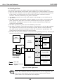
4.1 Overview
4.2 Logic Section
4.2.1 Logic section block diagram
4.2.2 Logic section components
4.3 Power Supply Section
4.3.1 Block diagram of power supply section
4.3.2 Power supply section structure
5. DETECTION FUNCTIONS
5.1 Sensor Functions
5.2 Other Detection Functions
5.2.1 Waste ink level detection
5.2.2 BJ cartridge sensor
5.2.3 Ink-out detection
5.2.4 No ink tank detection
55555-
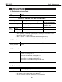
1. MAINTENANCE
1.1 Periodically-replaced Parts
1.2 Worn Parts
1.3 Consumables
1.4 Periodic Maintenance
Part 5: MAINTENANCE
1
1
1
1
1
IV
Page
5- 2
5- 2
5- 3
5- 6
5- 6
5- 6
5- 6
5- 7
5- 8
5- 8
5- 9
5- 9
5- 9
5 -10
5 -11
5 -11
5 -11
5 -11
5 -11
5 -12
5 -12
5 -12
5 -12
5 -13
5 -13
5 -16
5 -32
5 -32
5 -38
5 -42
5 -42
5 -43
5 -44
5 -45
5 -46
5 -47
5 -48
5 -48
5 -48
5 -50
5 -51
5 -53
5 -53
5 -65
5 -68
5 -69
5 -70
5 -71
5 -72
2. SERVICE TOOLS
2.1 List of Tools
3. APPLYING GREASE
4. DISASSEMBLY/ASSEMBLY
4.1 About Disassembly/Assembly
4.2 Precautions for Disassembly/Assembly
4.2.1 Unlocking the carriage
4.2.2 Disassembly prohibited parts
4.2.3 Purge unit tubes
4.2.4 Screw fastening of idle pulley ass'y
4.3 Logic Board Replacement
4.3.1 Except for EEPROM replacement
4.3.2 EEPROM replacement
4.4 Waste Ink Absorber Replacement
5. ADJUSTMENT
5.1 Adjustment Locations
5.1.1 EEPROM (IC501) and waste ink absorber
5.1.2 Adjusting the printing position of BJ cartridges
5.1.3 Carriage belt tension adjustment
6. TROUBLESHOOTING
6.1 Overview of Troubleshooting
6.1.1 Definition
6.1.2 Precautions for troubleshooting
6.2 Error Condition Diagnosis
6.2.1 Diagnosis flowchart
6.2.2 Error recovery
7. CONNECTOR POSITION & SIGNAL ASSIGNMENT
7.1 Logic Board
7.2 Carriage Board
7.3 Panel Board
7.4 Carriage Driver Board
7.5 Upper Cassette Board
7.6 Lower Cassette Board 1
7.7 Lower Cassette Board 2
7.8 Fan Board
7.9 Power Supply Unit
8. CIRCUIT DIAGRAMS
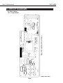
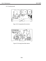
8.1 Parts Layout
8.1.1 Logic board
8.1.2 Carriage board
8.1.3 Panel board
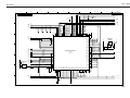
8.2 Circuit Diagrams
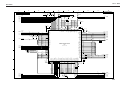
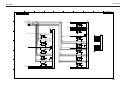
8.2.1 Logic board
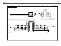
8.2.2 Carriage board
8.2.3 Carriage driver board
8.2.4 Ink sensor/Fan board
8.2.5 Panel board
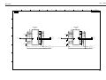
8.2.6 Upper cassette board
8.2.7 Lower cassette board
V
III. ILLUSTRATION INDEX
Page
1- 1
1- 2
1- 3
1- 3
1- 4
1- 5
1- 6
1- 8
1- 8
1- 9
1- 9
1 -10
1 -10
1 -11
1 -12
1 -12
1 -15
1 -16
1 -16
Part 1: SAFETY AND PRECAUTIONS
Figure
Figure
Figure
Figure
Figure
Figure
Figure
Figure
Figure
Figure
Figure
Figure
Figure
Figure
Figure
Figure
Figure
Figure
Figure
1- 1
1- 2
1- 3
1- 4
1- 5
1- 6
1- 7
1- 8
1- 9
1 -10
1 -11
1 -12
1 -13
1 -14
1 -15
1 -16
1 -17
1 -18
1 -19
Moving Sections of the Printer
Ink Path
BC-80, BC-81, and BC-82 Photo
Ink Mist
Power Supply Unit
Removing the Protective Cap
BJ Cartridges
Removing the Ink Tank Protective Cap
Ink Outlets
Spurs
Encoder Film and Carriage Board
Paper Feed Roller
Purge Motor
Contact Sections
Capping
Precautions when Carrying the Printer
Electronic System
Disassembly Prohibited Parts
How to Release Plastic Hooks
Part 2: PRODUCT SPECIFICATIONS
2- 1
2- 3
2- 3
2- 4
2- 4
2- 6
2- 7
2 -12
2 -18
2 -18
2 -18
Figure
Figure
Figure
Figure
Figure
Figure
Figure
Figure
Figure
Figure
Figure
3- 1
3- 2
3- 3
3- 4
3- 4
3- 5
3- 5
3- 6
3- 7
3- 8
3- 8
3- 9
3 -10
3 -11
3 -13
3 -14
Figure
Figure
Figure
Figure
Figure
Figure
Figure
Figure
Figure
Figure
Figure
Figure
Figure
Figure
Figure
Figure
2- 1
2- 2
2- 3
2- 4
2- 5
2- 6
2- 7
2- 8
2- 9
2 -10
2 -11
External View of Printer
Black BJ Cartridge [BC-80]
Color BJ Cartridge [BC-81]
Photo BJ Cartridge [BC-82 Photo]
Path of Ink Tank and BJ Cartridge (Front View)
BJ Cartridge Container [SB-80]
Ink Tanks
Printing Area
Compatibility Mode Timing Chart
Nibble Mode Timing Chart
ECP Mode Timing Chart
Part 3: OPERATING INSTRUCTIONS
3- 1
3- 2
3- 3
3- 4
3- 5
3- 6
3- 7
3- 8
3- 9
3 -10
3 -11
3 -12
3 -13
3 -14
3 -15
3 -16
Packing (1)
Packing (2): Lower Cassette
Installation Space
Connecting the Interface Cable
Connecting the Power Supply
Removing the Protective Cap
Installing BJ Cartridges
Checking the Position of the Print Head (1)
Checking the Position of the Print Head (2)
Replacing Ink Tanks
How to Remove the Ink Tank Protective Cap
BJ Cartridge Container SB-80
Precautions When Turning the Printer OFF
Paper Settings
Names and Functions of Parts (1)
Names and Functions of Parts (2)
VI
Page
3 -15
3 -16
3 -16
3 -17
3 -18
3 -19
3 -20
3 -22
3 -25
Figure
Figure
Figure
Figure
Figure
Figure
Figure
Figure
Figure
3 -26
Figure 3 -26
3 -28
Figure 3 -27
3 -17
3 -18
3 -19
3 -20
3 -21
3 -22
3 -23
3 -24
3 -25
Transporting the Printer
Capping Lock
Capping Lock/Unlock
Control Panel
BJ Cartridges do not Match Warning (Sample)
Windows 95/98 Printer Driver Maintenance Sheet (Sample)
Macintosh Printer Driver Utility Sheet (Sample)
Special Settings (Sample)
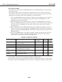
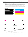
Nozzle Check Pattern (Sample using Black BJ cartridge BC-80+ Color
BJ cartridge BC-81)
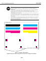
Nozzle Check Pattern (Sample using Color BJ cartridge BC-81+ Photo
BJ cartridge BC-82 Photo)
EEPROM List Print (Sample)
Part 4: TECHNICAL REFERENCE
4- 1
4- 2
4- 3
4- 4
4- 5
4- 6
4- 7
4- 8
4- 9
4 -11
4 -12
4 -13
4 -14
4 -15
4 -17
4 -18
4 -19
4 -20
4 -22
4 -22
4 -22
4 -24
4 -27
4 -28
4 -29
4 -30
4 -30
4 -31
4 -31
4 -32
4 -33
4 -33
4 -33
4 -34
4 -35
4 -36
4 -37
4 -37
Figure
Figure
Figure
Figure
Figure
Figure
Figure
Figure
Figure
Figure
Figure
Figure
Figure
Figure
Figure
Figure
Figure
Figure
Figure
Figure
Figure
Figure
Figure
Figure
Figure
Figure
Figure
Figure
Figure
Figure
Figure
Figure
Figure
Figure
Figure
Figure
Figure
Figure
4- 1
4- 2
4- 3
4- 4
4- 5
4- 6
4- 7
4- 8
4- 9
4 -10
4 -11
4 -12
4 -13
4 -14
4 -15
4 -16
4 -17
4 -18
4 -19
4 -20
4 -21
4 -22
4 -23
4 -24
4 -25
4 -26
4 -27
4 -28
4 -29
4 -30
4 -31
4 -32
4 -33
4 -34
4 -35
4 -36
4 -37
4 -38
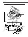
Printer Block Diagram
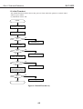
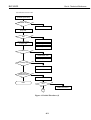
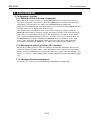
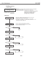
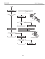
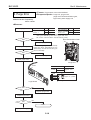
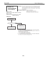
Initial Flowchart (1)
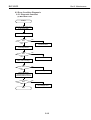
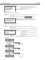
Initial Flowchart (2)
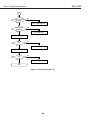
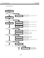
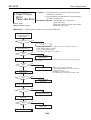
Initial Flowchart (3)
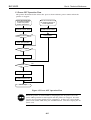
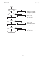
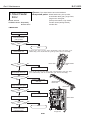
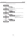
Power OFF Operation Flow
Print Signal Flow
Printing Drive Control
Interface Timing (Nibble Mode)
Interface Timing (ECP Mode)
Ink Layering with the Ink Optimizer
Main Sheet (Sample)
Advanced Detailed Setting (Sample)
Custom Setting
Printer Mechanism
BJ Cartridge Structure
Exploded View of BJ Head Unit
Nozzle Arrangement
BJ Cartridge I/O Signals
BJ Cartridge Drive Circuit Block Diagram
Head Temperature Sensor
Rank Wiring Diagram
Purge Unit
Purge Unit
Carriage Unit
Structure of Encoder Film and Encoder Head
Pick-up Path from Sheet Feeder Unit/Manual Feed Slot
Pick-up Path from Upper Cassette/Lower Cassette Units
Paper Feed Section
Platen Ribs
Structure of Sheet Feeder Unit
Cassette Body and Claws
Structure of Cassette Unit
Mechanical Clutch of Upper Cassette
Structure of Flapper Unit
Path of Fan Air Flow
Printer Electrical Section
Logic Board Block Diagram
Printer Block Diagram
VII
Page
4 -41
4 -42
4 -43
4 -46
4 -47
4 -48
Figure
Figure
Figure
Figure
Figure
Figure
5- 3
5- 4
5- 5
5- 6
5- 7
5- 7
5- 8
5- 8
5- 9
5 -10
5 -32
5 -38
5 -42
5 -42
5 -43
5 -44
5 -45
5 -46
5 -47
5 -48
5 -49
5 -50
5 -50
5 -51
Figure
Figure
Figure
Figure
Figure
Figure
Figure
Figure
Figure
Figure
Figure
Figure
Figure
Figure
Figure
Figure
Figure
Figure
Figure
Figure
Figure
Figure
Figure
Figure
4 -39
4 -40
4 -41
4 -42
4 -43
4 -44
Block Diagram of Power Supply Section
Output Connectors
Sensor Locations
Principle of Ink-out Detection
Ink Sensor and Anti-reflection Sheet
Principle of No Ink Tank Detection
Part 5: MAINTENANCE
5- 1
5- 2
5- 3
5- 4
5- 5
5- 6
5- 7
5- 8
5- 9
5 -10
5 -11
5 -12
5 -13
5 -14
5 -15
5 -16
5 -17
5 -18
5 -19
5 -20
5 -21
5 -22
5 -23
5 -24
Grease Application Sections (1)
Grease Application Sections (2)
Grease Application Sections (3)
Unlocking the Carriage
BJ Cartridge Contact Section on Carriage Unit
Disassembly Prohibited Locations
Purge Unit Tubes
Screw Fastening of Idle Pulley Ass'y
EEPROM
Waste Ink Absorber
Logic Board
Carriage Board
Panel Board
Carriage Driver Board
Upper Cassette Board
Lower Cassette Board 1
Lower Cassette Board 2
Fan Board
Power Supply Unit
Logic Board Front Surface
Logic Board Rear Surface
Carriage Board Front Surface
Carriage Board Rear Surface
Panel Board Front Surface
VIII
IV. TABLE INDEX
Part 2: PRODUCT SPECIFICATIONS
Page
2- 5
2 -11
TABLE 2 - 1
TABLE 2 - 2
3 -11
3 -17
3 -18
3 -24
TABLE
TABLE
TABLE
TABLE
4 -10
TABLE 4 - 1
4 -12
4 -12
4 -20
4 -21
4 -23
4 -25
TABLE
TABLE
TABLE
TABLE
TABLE
TABLE
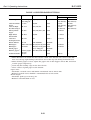
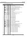
CARTRIDGE AND PRINTING MODES
PAPER SPECIFICATIONS
Part 3: OPERATING INSTRUCTIONS
3333-
1
2
3
4
PRINTER PAPER SETTINGS
OPERATOR CALL
SERVICE CALL
SERVICE MODE
Part 4: TECHNICAL REFERENCE
444444-
2
3
4
5
6
7
PRINTER DOT PITCH NUMBER OF PASSES, NUMBER OF
EJECTION NOZZLES
CARRIAGE SPEED
MAIN AUTO PALETTE DEFAULTS (Windows 95/98)
INK TYPE EJECTED FROM BJ CARTRIDGES
BJ CARTRIDGE I/O SIGNALS
HEAD ID AND RANKOUT OUTPUT LEVEL
CLEANING EXECUTION CONDITIONS, CLEANING TIME AND INK
SUCTION AMOUNTS
Part 5: MAINTENANCE
5- 1
TABLE 5 - 1
PERIODICALLY-REPLACED PARTS
IX
Part 1
SAFETY AND
PRECAUTIONS
Page
1- 1
1- 1
1- 2
1- 4
1- 5
1- 5
1- 8
1- 9
1 -13
1 -13
1 -14
1 -15
1 -16
1 -17
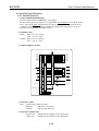
1. PERSONAL SAFETY PRECAUTIONS
1.1 Moving Sections of the printer
1.2 Ink Stains
1.3 Electrically Live Sections of the Printer
2. MACHINE PRECAUTIONS
2.1 Handling BJ Cartridges
2.2 Handling the Ink Tanks
2.3 Handling the Printer
3. PRECAUTIONS FOR SERVICE
3.1 Precautions Concerning Memory Data
3.2 Special Settings
3.3 Precautions to Prevent Damage from Static Electricity
3.4 Precautions for Disassembly/Assembly
3.5 Self-diagnostic Functions
Part 1: Safety and Precautions
BJC-8500
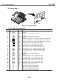
1. PERSONAL SAFETY PRECAUTIONS
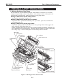
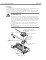
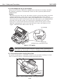
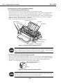
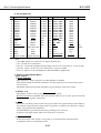
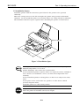
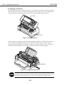
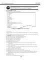
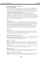
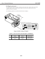
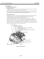
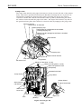
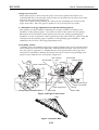
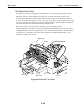
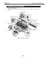
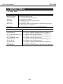
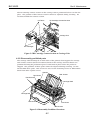
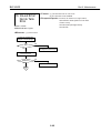
1.1 Moving Sections of the Printer
Be careful not to let your hands or fingers, hair, clothes, accessories, etc., become
caught in any moving sections of the printer. The moving sections of the printer are
driven by the carriage motor, paper feed motor, or the purge motor.
Moving sections driven by the carriage motor:
Carriage belt, idle pulley, carriage, etc.
Moving sections driven by the paper feed motor:
Paper feed rollers, pinch roller, cleaning unit, eject roller, spur unit, transmission
gear, flapper unit, etc.
Moving sections driven by the purge motor:
Purge unit, pick-up roller of the sheet feeder unit, pick-up rollers in the upper and
lower cassettes, paper feed roller, etc.
During operation close the top cover (except when checking operation), and take care
not to touch the above moving parts. Also note that the spurs are made of metal and
have sharp edges. Avoid touching these inadvertently with bare hands.
Idle Pulley
Carriage Belt
Carriage Belt
Top Cover
Pick-up Roller
Sheet Feeder Unit
Transmission
Gear
Pinch Roller
Carriage Motor
Pick-up Rollers
Paper Feed Rollers
Purge Unit
Upper Cassette
Purge Motor
Flapper Unit
Paper Feed Roller
Cleaning Unit
Paper Feed Motor
Spur Unit
Eject Roller
Lower Cassette
Figure 1-1 Moving Sections of the Printer
1-1
Part 1: Safety and Precautions
BJC-8500
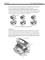
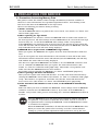
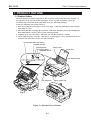
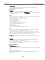
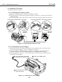
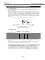
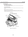
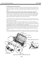
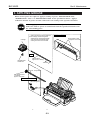
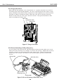
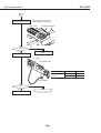
1.2 Ink Stains
1.2.1 Ink path
Be careful not to touch the ink path on the printer, or get ink stains on your hands or
fingers, clothing, printer while it is operating and on the work table.
The ink path is comprised of the nozzle section of BJ cartridges, suction caps, waste
ink tubes, wiper section, wiper cleaner, maintenance jet section, wiper unit, wiper
unit transfer pad and waste ink absorber.
CAUTION
The ink and plain paper ink optimizer are not substances harmful to the
human body. They do, however, contain organic solvents (Ink: isopropyl
alcohol 67-63-0, glycerin 56-81-5, Plain Paper Ink optimizer: ethleneglycol
111-46-6, glycerin 56-81-5). Be careful not to get any ink in your mouth
or eyes. Also, keep ink and plain paper ink optimizer out of the reach of
small children.
If you do get any into your eyes, wash it out immediately with plenty of water.
If you inadvertently swallow a large amount of ink, consult a doctor
immediately.
Since ink contains dyes, if it gets on your clothes, etc., it will not come out
even through washing.
Black BJ Cartridge BC-80 or
Photo BJ Cartridge BC-82 Photo
Ink Tanks
Carriage
Cleaning Unit Transfer Pad
Color BJ Cartridge BC-81
Suction Caps
Wiper Cleaner
Wiper Unit
Cleaning Unit
(exclusively for Black BJ cartridge BC-80)
Purge Unit
Maintenance Jet Section
Waste Ink Tubes
Waste Ink Absorber
Figure 1-2 Ink Path
1-2
Part 1: Safety and Precautions
BJC-8500
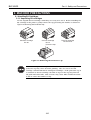
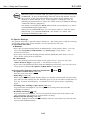
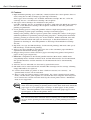
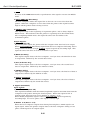
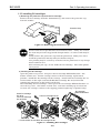
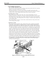
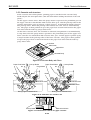
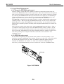
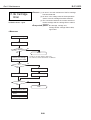
The ink path includes the filters of the Black BJ cartridge [BC-80], Color BJ cartridge
[BC-81] and Photo BJ cartridge [BC-82 photo], and each ink outlet of the ink tanks.
Take care of the ink path when handling BJ cartridges and ink tanks.
Never unnecessarily remove ink tanks from BJ cartridges. When an ink tank is
removed from a BJ cartridge, air can enter the ink path and may adversely affect
printing. If an ink tank is removed from a BJ cartridge, carry out cleaning. (Cleaning
is automatically carried out when the ink tank is attached after a no ink tank error is
detected. For details, see "Part 4: TABLE 4-7 CLEANING EXECUTION CONDITIONS,
CLEANING TIME AND INK SUCTION AMOUNTS." (page 4-25))
Ink Outlet
Filter
Black BJ Cartridge
BC-80
Color BJ Cartridge
BC-81
Photo BJ Cartridge
BC-82 Photo
Figure 1-3 BC-80, BC-81, and BC-82 Photo
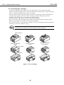
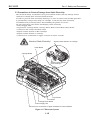
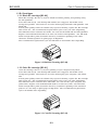
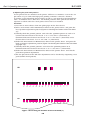
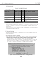
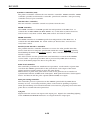
1.2.2 Ink mist
With the BJ cartridges used on this printer, minute ink droplets rise up and bounce
back from the paper during printing as "ink mist." This printer generates a much
larger amount of ink mist than conventional Canon printers. As a countermeasure,
two fans, A and B, are provided to create an air path to draw the ink mist behind fan
B into the ink mist absorber. Fan A pulls in air, while fan B sucks in this blown air.
When servicing or disassembling this printer, wear gloves. Hands, fingers or clothes
may become soiled by this ink mist. If necessary, wipe off ink mist using a soft cloth
moistened with water.
Fan B
Ink Mist Absorber
Fan A
Figure 1-4 Ink Mist
1-3
Part 1: Safety and Precautions
BJC-8500
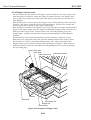
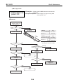
1.3 Electrically Live Sections of the Printer
All electrical sections of the printer supplied with AC power are electrically live when
the power cord is connected whether the printer is turned ON or OFF using the POWER
button.
Be careful of electric shock when checking printer operation with the covers removed
during servicing. For this reason, be sure to unplug the power cord from the power
outlet during servicing.
CAUTION
As the AC main voltage is supplied to the primary side of the power supply
unit, there is always the danger of an electric shock.
Always unplug the AC power cord before disassembling for service.
Figure 1-5 Power Supply Unit
1-4
Part 1: Safety and Precautions
BJC-8500
2. MACHINE PRECAUTIONS
2.1 Handling BJ Cartridges
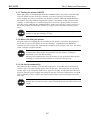
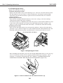
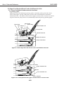
2.1.1 Unpacking BJ cartridges
Do not unpack the BJ cartridges until they are ready to be used. Before installing the
BJ cartridge in the printer, gently remove the cap protecting the nozzles as shown in
Figure 1-6 Removing the Protective Cap.
Black BJ Cartridge
BC-80
Color BJ Cartridge
BC-81
Photo BJ Cartridge
BC-82 Photo
Protective Cap
Figure 1-6 Removing the Protective Cap
Never re-use a protective cap once it has been removed. Re-using a
protective cap may cause defective printing. Also, be sure to use BJ
cartridge container SB-80 for storing BJ cartridges. If the protective cap is
re-attached to the BJ cartridge, the film or tape on the cap may form an
ink path with other inks. This, in turn, may cause inks of different colors
to mix or cause the nozzles to clog.
1-5
Part 1: Safety and Precautions
BJC-8500
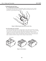
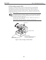
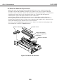
2.1.2 Protecting BJ cartridges
To prevent clogging of the nozzles due to foreign matter, never touch the nozzle
section of the BJ cartridge, filters, and ink outlets on the ink tanks, or wipe off foreign
matter or clogged ink with tissue paper or the like.
Once you have removed the protective cap from a BJ cartridge, either install the BJ
cartridge in the printer or store it in the cartridge container (SB-80) to prevent
clogging of the nozzles due to ink drying or foreign matter.
Do not re-attach a protective cap once it has been removed.
Also, never leave a BJ cartridge exposed with the ink tank removed. (Doing so may
allow the ink outlets to dry and cause defective printing.)
Do not disassemble or assemble BJ cartridges, and do not wash the heads with water
as this may cause the nozzles to clog.
Clogging of the nozzles causes defective printing. If cleaning does not
restore proper printing, you must replace the BJ cartridge.
Nozzle Section
Black BJ Cartridge
BC-80
Color BJ Cartridge
BC-81
Ink Outlets
Filters
Figure 1-7 BJ Cartridges
1-6
Photo BJ Cartridge
BC-82 Photo
Part 1: Safety and Precautions
BJC-8500
2.1.3 Turning the printer ON/OFF
When the power is switched OFF with the POWER button, the printer automatically
caps the nozzle section of the BJ cartridge to protect it and prevent ink leakage.
If you unplug the power cord before the printer is turned OFF with POWER button,
the printer may stop without capping the nozzles, depending on the position of the
carriage. If this happens, reconnect the power cord, start up the printer as usual,
turn the power OFF with the POWER button, make sure that the carriage returns to
the home position and that the nozzles are capped before disconnecting the power
cord.
If the nozzle section is not capped, ink may leak or dry, causing the
nozzles on the BJ cartridges to clog.
2.1.4 When not using the printer
Keep the Color BJ cartridge BC-81 installed in the printer even when the printer is
not in use to ensure the quality of the BJ cartridge. Install either the Black BJ
cartridge BC-80 or Photo BJ cartridge BC-82 photo in the printer, and store the other
in BJ cartridge container SB-80.
If the BJ cartridge is removed from the printer and left unprotected,
foreign matter may stick or dry ink may clog the nozzles, making it
impossible to use the BJ cartridge.
Ink may also leak from the caps if cleaning is not performed after the BJ
cartridge is removed and the printer is carried or transported.
2.1.5 Ink electroconductivity
The ink in the BJ cartridge is electrically conductive. If it leaks onto a mechanical
section, wipe it up with a damp paper towel or the like. If it leaks onto an electrical
circuit, wipe it up completely with tissue paper or the like. If ink leaks onto the logic
board or into the power supply unit and gets into the electrical components and PCB,
and is difficult to clean, replace the logic board or other electrical components with
new ones.
If the power cord is connected to the printer with ink leaked, this may
damage the electrical section. Never switch the power on if there has been
a leak.
1-7
Part 1: Safety and Precautions
BJC-8500
2.2 Handling the Ink Tanks
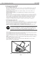
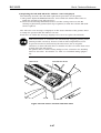
2.2.1 Unpacking the ink tanks
Do not unpack the ink tank from its package until it is ready to be used. Before
installing the ink tank in the BJ cartridge, unpack the ink tank and remove the
protective cap protecting the ink outlets.
Figure 1-8 Removing the Ink Tank Protective Cap
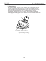
2.2.2 Protecting the ink tanks
To prevent poor ink suction due to foreign matter on the joints with the BJ cartridge,
never touch the ink outlets of the ink tank with your hands or fingers. After removing
the protective cap from the ink tank, immediately install the ink tank in the BJ
cartridge to prevent the nozzles from clogging due to ink drying. Do not remove ink
tanks from BJ cartridges unless replacing them. (When not using an ink tank, place
them, installed in the BJ cartridge, in BJ cartridge container SB-80.
Ink Outlets
Figure 1-9 Ink Outlets
1-8
Part 1: Safety and Precautions
BJC-8500
2.3 Handling the Printer
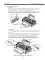
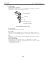
2.3.1 Spurs
Metal spurs are used for feeding and outputting paper after printing. The tips of the
spurs are also sharp and pointed. They are small and easily deformed. Take care not
to deform them. Take care to prevent injury when handling them.
If the tips of the spurs become deformed or worn, and their surface contact area with
the paper increases, a minute line of dots may appear on the paper. If this happens,
replace the spurs. (refer to "Part 5: 1.1 Periodically-replaced Parts" (page 5-1))
Spur Cleaner
Spurs
Figure 1-10 Spurs
2.3.2 Encoder
The BJ cartridge used on this printer generates a lot of ink mist as described in "Part
1: 1.2.2 Ink mist" (page 1-3). So, the encoder film and encoder head may become coated
with ink mist.
To clean the encoder film, wipe with lint-free paper or a dry cloth. Do not wipe with a
wet cloth. Replace the encoder film if wiping does not clean it. When replacing the
encoder film, make sure that it is installed facing the correct way. (The top of the
encoder film is marked as shown in Figure 1-11 Encoder Film and Carriage Board.)
Do not wipe off ink mist on the encoder head. Replace with a new head (mounted on
the carriage board.) (refer to "Part 5: 1.1 Periodically-replaced Parts" (page 5-1))
Encoder Film
Carriage Board
Figure 1-11 Encoder Film and Carriage Board
1-9
Part 1: Safety and Precautions
BJC-8500
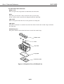
2.3.3 Paper feed roller unit
The surface of the paper feed roller is blast-finished to ensure a maximum resolution
of 1200 × 1200 dpi. Take care not to scratch the surface of this roller.
The drive gear used on the paper feed roller is also finished to high precision to feed
the paper in small increments for 1/1200 inch feeding. Take special care not to leave
any knock marks on this gear.
Drive Gear
Paper Feed Roller
Figure 1-12 Paper Feed Roller
2.3.4 Purge motor
The purge motor is very hot immediately after repeated printing or cleaning. Take
care not to touch the purge motor directly with bare hands after these operations.
Danger! High Temperature!
Figure 1-13 Purge Motor
1-10
Part 1: Safety and Precautions
BJC-8500
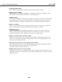
2.3.5 Precautions to prevent damage from static electricity
The electrical charge accumulated on a person when clothes rub can damage electric
elements or change their electrical characteristics. Never touch the contact section on
carriage top or the contact section on BJ cartridges.
Attention! Static Electricity!
Contact Section on Carriage Top
Contact Section on BJ Cartridges
Figure 1-14 Contact Sections
1-11
Part 1: Safety and Precautions
BJC-8500
2.3.6 Ink leakage/ink dry-up precautions
Always turn the printer OFF by the POWER button with the BJ cartridges installed.
The following operation is automatically carried out when powering OFF with the
POWER button.
Capping
The head cap covers and secures the nozzle section to prevent the nozzles on the BJ
cartridge from drying. If the power cord is unplugged from the power outlet by
mistake without turning the printer OFF by the POWER button, reconnect the power
cord to the power outlet, turn the power ON, then OFF again, by the POWER button,
and make sure that the nozzles are capped before unplugging the power cord.
If the power is turned OFF with the BJ cartridge removed or the power is turned
OFF after unplugging the power cord from the power outlet, the nozzles are not
capped. This may cause ink to leak or dry up.
BJ Cartridge
Head Cap
(enlarged view of indicated section)
Figure 1-15 Capping
If the power cannot be turned ON due to printer trouble, manually lock
the nozzle cap. For details, see "Part 3: 2.2 Capping Lock/Unlock" (page 3-16).
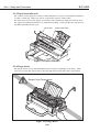
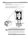
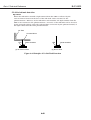
2.3.7 Precautions when carrying the printer
The printer weighs 25 kg. It should be carried by two personnel, holding it on both
sides as shown in Figure 1-16 Precautions when Carrying the Printer.
Figure 1-16 Precautions when Carrying the Printer
1-12
Part 1: Safety and Precautions
BJC-8500
3. PRECAUTIONS FOR SERVICE
3.1 Precautions Concerning Memory Data
This printer counts the number of BJ cartridge attachments/removals, number of
sheets fed, waste ink amount, head position adjustment values, and cleaning count,
and stores this data in the EEPROM on the logic board.
Observe the following precautions during servicing.
1) Before servicing:
Check the EEPROM with a test print in the service mode. For details, see "Part 3: 3.4.2
Service mode" (page 3-24).
2) When replacing the logic board:
If the EEPROM is not defective, remove the EEPROM from its socket and attach it to
the new logic board. All data settings stored to EEPROM can be used on the new logic
board as they are. To check the EEPROM data settings, make a test printout.
If the EEPROM is not attached to the new logic board, the amount of waste ink in the
waste ink absorber will not match the waste ink amount (stored in EEPROM), and ink
may leak without the waste ink error being displayed.
3) EEPROM defect (replacement of EEPROM or logic board):
When you replace the EEPROM, also replace all of the waste ink absorbers with new
ones.
If you do not replace the waste ink absorbers, the amount of waste ink in the waste
ink absorber will not match the waste ink amount (stored in EEPROM), and ink may
leak without the waste ink error being displayed.
The data in a replacement EEPROM is not defined. So, the EEPROM cannot be used
as it is. Initialize the EEPROM when you replace the waste ink absorbers. (For
details, see "Part 3: 3.4.2 Service mode" (page 3-24)). Then make a test printout, and
make sure that the EEPROM data has been defined.
For details on how to handle the EEPROM, see "Part 3: 3.6 EEPROM" (page 3-27).
4) After replacing a full waste ink absorber:
After you have replaced the waste ink absorber, reset the total waste ink amount by
clearing the EEPROM's waste ink level (for details, see "Part 3: 3.4.2 Service mode" (page
3-24)). Then make a test printout, and make sure that the waste ink amount has
been reset to zero. (For details, see "Part 3: 3.6.3 EEPROM list print" (page 3-28))
5) If the total waste ink amount is reset to zero, or the EEPROM is initialized by
mistake:
Take care when you clear or initialize the EEPROM. Data settings stored in EEPROM
cannot be restored once the EEPROM is cleared. If you have cleared EEPROM by
mistake, carry out the same process and settings for a defective EEPROM described in
3) above.
After the EEPROM is reset, the data it held cannot be printed out with a
test printout. If you want to check the stored data, be sure to execute a
test printout before resetting the EEPROM. Data in EEPROM also cannot
be rewritten via computer.
When the EEPROM is initialized, all data that was held in EEPROM is lost.
When you return the printer after servicing, reset the various function
settings (e.g. head position adjustment values) that were set by the user.
1-13
Part 1: Safety and Precautions
BJC-8500
When the printer is turned OFF, the printer updates the waste ink amount
in EEPROM. To prevent ink leakage when the waste ink amount exceeds
the capacity of the waste ink absorber, the printer stops printing and
displays a "waste ink full" error. If this happens, remedy the error by
following the instructions in "Part 5: 6.2.2 Error recovery 5. Waste Ink Warning
/ Waste Ink Full Error" (page 5-21).
For details on checking the EEPROM data with a test printout, see "Part 3:
3.6.3 EEPROM list print" (page 3-28).
When you clear EPPROM data, you can choose either to "clear the waste
ink amount" or to "initialize EEPROM." For details, see "Part 3: 3.6.2
Resetting the EEPROM" (page 3-27).
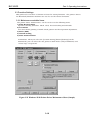
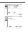
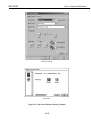
3.2 Special Settings
The printer driver has a special settings dialog box. This dialog box is only for servicing
and dealing with claims on the market. It is not disclosed to the user.
(1) Operation Procedure
In Windows:
• Select the [Custom Setting] button in Maintenance on the printer driver. You can
select the "Set printer to ECP mode" and "Pause page" setup items. ➝ not
disclosed to the user
• If you select the [Custom Setting] button with the [Shift] key held down, you can
select all five setup items in (2) below.
On a Macintosh:
• Select the [Settings] button in Utility on the printer driver. You can select the
"Pause Between Pages" setup item.➝ not disclosed to the user
• If you select the [Settings] button with the [Shift] key held down, you can select four
setup items (excluding "Set printer to ECP mode") in (2) below.
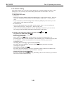
(2) Setup Items (underline indicates default ON=
, OFF=
)
• Set printer to ECP mode (OFF/ON)
Sets the printer interface to ECP.
• Pause Page (OFF/ON)
When pages containing high-density images are printed continuously, the preceding
page may become smudged by the following page if you do not allow enough time for
it to dry. In such circumstances, set whether or not to pause before outputting
pages.
• Cleaning after cartridge replacement (OFF/ON)
To prevent ink consumption, set not to perform cleaning when the head (BJ
cartridge) is replaced.
• Economy Cleaning (OFF/ON)
To prevent ink consumption, set not to perform cleaning at the first software ON
after a hardware ON and not to perform timer cleaning.
• Display low ink warning (OFF/ON)
Set not to display low ink warning (Disabling "ink-out" detection) to prevent the ink
sensors from malfunctioning.
1-14
Part 1: Safety and Precautions
BJC-8500
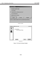
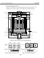
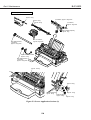
3.3 Precautions to Prevent Damage from Static Electricity
The electrical charge accumulated on a person when clothes rub can damage electric
elements or change their electrical characteristics.
In order to prevent static electricity discharge, be sure to touch some metallic part that
is grounded by using a wrist strap, for example, to release the static electricity
accumulated on your body before disassembling the printer for service.
Do not touch these parts before discharging static electricity:
• Power Supply Unit
• Logic Board, Carriage Board, Carriage Driver Board, Panel Board, Fan Board
• Connector and Contact for Each Cable
• Signal Contact Section on BJ Cartridges
• Signal Contact Section on Carriage
• Connector for Connection to Upper Cassette on Lower Cassette
Attention! Static Electricity!
Signal Contact Section on Carriage
Panel Board
Carriage Board
Signal Contact Section
on BJ Cartridge
Logic Board
Fan Board
Carriage Driver Board
Power Supply Unit
Connector for Connection to Upper Cassette on Lower Cassette
Figure 1-17 Electronic System
1-15
Part 1: Safety and Precautions
BJC-8500
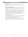
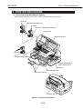
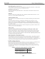
3.4 Precautions for Disassembly/Assembly
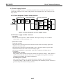
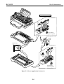
3.4.1 Disassembly prohibited parts
Never loosen the red screws on the printer's mechanical sections.
Two red screws are used for fixing the adjustment plate. This plate determines the
distance between the nozzles on the BJ cartridge and the platen. This distance is
called the "head gap." Ten red screws are used for fixing the carriage rail and chassis.
These screws are adjusted to their optimum positions before the printer is shipped
from the factory, and cannot be re-adjusted.
Also, do not disassemble BJ cartridges and ink tanks.
Carriage Rail
Red Screws
Ink Tanks
Red Screws
Ink Tanks
Red Screw
Red Screw
Red Screws
BJ Cartridge
Red Screws
Figure 1-18 Disassembly Prohibited Parts
Do not disassemble parts on the printer down to components smaller than
those indicated in the exploded views in the Parts Catalog. Doing so might
impair their original functions after they are re-assembled.
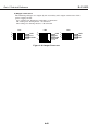
3.4.2 Precautions for disassembly/assembly
Before you start disassembly/assembly, be sure to read "Part 5: 4. Disassembly/Assembly"
(page 5-6) for details on parts that require special caution during disassembly/assembly.
The printer comprises combining many plastic parts. When disassembling the
printer, be careful not to break or bend these plastic hooks.
Never apply excessive force
when releasing a hook.
Hook
Figure 1-19 How to Release Plastic Hooks
Some of the plastic parts contain glass fibers for improving the strength of
the part. However, since their viscosity is low, plastic hooks break easily.
Do not apply excessive force when releasing a hook.
1-16
Part 1: Safety and Precautions
BJC-8500
3.5 Self-diagnostic Functions
The printer has built-in self-diagnostic functions to analyze hardware defects. The
results of self-diagnosis are indicated by the indicators on operational panel and the
beeper. For details, see "Part 3: 3.1 Error Indications" (Page 3-17).
1-17
Part 1: Safety and Precautions
BJC-8500
This page intentionally left blank
1-18
Part 2
PRODUCT
SPECIFICATIONS
Page
2- 1
2- 1
2- 2
2- 3
2- 6
2- 7
2- 8
2- 8
2 -11
2 -13
1. PRODUCT OUTLINE
1.1 Product Outline
1.2 Features
1.3 BJ Cartridges
1.4 BJ Cartridge Container SB-80
1.5 Consumables
2. SPECIFICATIONS
2.1 General Specifications
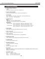
2.2 Paper Specifications
2.3 Interface Specifications
Part 2: Product Specifications
BJC-8500
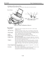
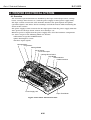
1. PRODUCT OUTLINE
1.1 Product Outline
The BJC-8500 is a printer targeted for the corporate and professional use market. It
incorporates next-generation BJ cartridges, and is capable of printing 1200 dpi
resolution full-color and black-and-white on a par with LBP printing.
It has the following four main features:
1. Next-generation BJ cartridges ensure real 1200 × 1200 dpi printing in either blackand-white or color.
2. The Photo Kit (BJ cartridge: BC-82 Photo, Ink tank: BCI-8PC photo, BCI-8PM photo,
BCI-8PBK photo) ensures photo-grade printing quality.
3. Printing up to A3+ size (329 × 483) and A4+ full-bleed (223.5 × 355.6)
4. Large-capacity paper cassette. 600 sheets of plain paper can be stacked if the lower
cassette and auto sheet feeder are also attached.
BJ Cartridge REPLACE Button
POWER Indicator
POWER Button
ERROR Indicator
RESUME Button
Paper Guide
Paper Rest
POWER
ERROR
RESUME
Auto Sheet Feeder
Tray Extension
Paper Output Tray
Top Cover
Flapper
Figure 2-1 External View of Printer
2-1
Part 2: Product Specifications
BJC-8500
1.2 Features
1. High-definition printing up to 1200 (H) × 1200 (V) (when the Canon printer driver is
used) using the new BJ cartridge type (600 dpi resolution).
Three types of BJ cartridges are available: Black BJ cartridge "BC-80", Color BJ
cartridge "BC-81", and Photo BJ cartridge "BC-82 photo."
2. Two types of BJ cartridges are installed on the printer.
Color BJ cartridge "BC-81" is installed at all times, with either the Black BJ cartridge
"BC-81" or the Photo BJ cartridge "BC-82 photo" installed to meet the particular
printing requirements.
3. A new printing process using ink optimizer achieves high waterproofing properties
when printing on plain paper (including envelopes and thick paper).
During color printing, this new process prints after coating the surface of the paper
with ink optimizer for promoting waterproofing properties. During black-and-white
printing, printing is carried out by one of two methods. Either black ink, then ink
optimizer and then black ink again are discharged, or black ink followed by ink
optimizer is discharged. The ink optimizer is discharged from Black BJ cartridge
"BC-80."
4. HQ mode: 213 cps (10 kHz discharge, bi-directional printing), HS mode: 683 cps (8
kHz discharge, bi-directional printing)
5. There is no paper thickness selection lever due to the automatic paper thickness
adjustment mechanism (moving platen).
6. Flapper unit prevents contact between paper currently being printed and printed
paper on the paper output tray.
7. IEEE1284-compatible bi-directional parallel interface (ECP mode, nibble mode,
compatibility mode: Default is nibble mode and RS-422 interface for the Macintosh.
The parallel interface and the interface for the Macintosh can be automatically
switched.)
8. "Ink out" and "no ink tank" are detected by optical ink sensor.
9. Ink tanks can be removed from the installed BJ cartridges on the carriage, allowing
empty ink tanks to be replaced.
10. Canon's first bubble jet printer to have a built-in cassette (1st cassette) ; an
optional 2nd cassette can be attached.
11. There is only one built-in printer control mode, the Canon extended mode (native
mode). In this mode, print signals are sent from the host computer after they have
been converted to Canon extended mode by the Canon printer driver. Emulation
mode is not supported.
Printing processes using the ink optimizer are applied in both black-andwhite and color printing in printing modes other than draft mode when the
paper type is set to plain paper, envelope, or thick paper on the printer
driver. The ink optimizer is not discharged when the paper type is set to
special paper or film on the printer driver.
The "ink out detection" function detects running out of ink and displays
an error before printing becomes defective (e.g. faint printing) due to lack
of ink.
2-2
Part 2: Product Specifications
BJC-8500
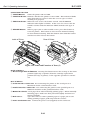
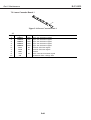
1.3 BJ Cartridges
1.3.1 Black BJ cartridge [BC-80]
Black BJ cartridge "BC-80" is used for black-and-white printing and printing using
the ink optimizer.
It has three BJ heads, each having 256 nozzles (two staggered 128-nozzle rows),
arranged in parallel. The heads are used for discharging black ink, ink optimizer, and
black ink.
If ideal print quality cannot be obtained by repeated cleaning, replace the BJ cartridge
with a new one. The recommended replacement cycle is one year after unpacking.
The ink tank section contains two tanks, one each for the black ink and ink optimizer.
Replace each individual ink tank as it runs out of ink or ink optimizer. One ink tank
holds enough ink to print about 940 sheets by continuous printing of the 1500character standard pattern on plain paper in HQ mode.
The recommended replacement cycle for ink tanks is six months after unpacking.
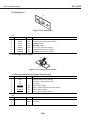
Figure 2-2 Black BJ Cartridge [BC-80]
1.3.2 Color BJ cartridge [BC-81]
Color BJ cartridge "BC-81" is used for printing of cyan, magenta and yellow.
It has three BJ heads, each having 256 nozzles (two staggered 128-nozzle rows),
arranged in parallel. The heads are used for discharging cyan, magenta, and yellow
ink.
If ideal print quality cannot be obtained by repeated cleaning, replace the BJ cartridge
with a new one. The recommended replacement cycle is one year after unpacking.
The ink tank section contains three ink tanks, one each for the cyan, magenta and
yellow inks. Replace each individual ink tank as it runs out of ink. One ink tank
holds enough ink to print about 450 sheets by continuous printing of the standard
pattern at 7.5% duty on plain paper in HQ mode. The recommended replacement
cycle is 6 months after unpacking.
Figure 2-3 Color BJ Cartridge [BC-81]
2-3
Part 2: Product Specifications
BJC-8500
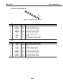
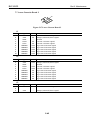
1.3.3 Photo BJ cartridge [BC-82 Photo]
Photo BJ cartridge "BC-82 photo" supports photo-realism (super photo mode, printing
of natural images containing lots of light color and midtones), and is used for printing
photo black, photo cyan and photo magenta.
It has three BJ heads, each having 256 nozzles (two staggered 128-nozzle rows),
arranged in parallel. The heads are used for discharging photo black, photo cyan and
photo magenta ink.
If ideal print quality cannot be obtained by repeated cleaning, replace the BJ cartridge
with a new one. The recommended replacement cycle is one year after unpacking.
The ink tank section contains three ink tanks, one each for photo black, photo cyan
and photo magenta inks. Replace each individual ink tank as it runs out of ink. One
ink tank holds enough ink to print about 390 sheets by continuous printing of the
photo printing standard pattern. The recommended replacement cycle is 6 months
after unpacking.
Figure 2-4 Photo BJ Cartridge [BC-82 Photo]
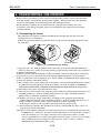
Ink Path between BJ Cartridges and Ink Tanks
The three BJ heads of Black BJ cartridge BC-80 are arranged in order
from the left: black, ink optimizer, and black. The ink tanks are arranged
in order from the left: ink optimizer and black.
So, the three ink paths inside the BJ cartridge cross each other at one
point. As all BJ cartridges are structured the same, the three ink paths in
color BJ cartridge BC-81 and photo BJ cartridge BC-82 photo also cross
each other at one point. When you install the ink tanks on the BJ
cartridges, make sure that they are installed at the correct locations by
checking the seal affixed on the main case.
Photo Black
Photo Magenta
Photo Cyan
Photo Magenta
Yellow
Photo Black
Yellow
Magenta
Photo Cyan
Cyan
Magenta
Black
Ink Optimizer
Ink Tank
BJ Cartridge
Cyan
Black
Ink Optimizer
Black
Ink Paths
Black
BJ Cartridge
BC-80
Color
BJ Cartridge
BC-81
Photo
BJ Cartridge
BC-82 Photo
Figure 2-5 Path of Ink Tank and BJ Cartridge (Front View)
2-4
Part 2: Product Specifications
BJC-8500
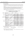
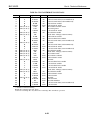
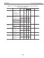
1.3.4 Relationship between BJ cartridges and printing mode
The following table shows which inks are used in each printing mode.
TABLE 2-1 CARTRIDGE AND PRINTING MODES
Color BJ Photo BJ
Cartridge Cartridge
BC-81 BC-82 Photo
Black Ink Ink Optimizer Color Ink Photo Ink
●
●
Black BJ Cartridge
BC-80
Printing Modes
Black-and- Plain paper, envelope, thick paper
white
(print quality: other than high-speed)
Plain paper, envelope, thick paper
(print quality: high-speed)/special media
Color
Plain paper, envelope, thick paper
(print quality: other than high-speed)
Plain paper, envelope, thick paper
(print quality: high-speed)/ special media
Super
Special paper
Photo
●
●
●
●
●
●
●
●
●: Used
Blank: Unused
Note that Color BJ Cartridge BC-81 is installed at all times.
When handling BJ cartridges and ink tanks, observe the precautions
described in "Part 1: 2.1 Handling BJ Cartridges" (page 1-5).
2-5
Part 2: Product Specifications
BJC-8500
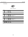
1.4 BJ Cartridge Container SB-80
This container is for storing either the Black BJ cartridge "BC-80" or Photo BJ cartridge
"BC-82 photo" that is removed from the printer when selectively using these cartridges
for printing.
This container is packaged together with the printer, and is also available from stores
as an option.
When storing a BJ cartridge inside the container, close the lid securely. If you leave the
lid open, the ink may dry and clog the nozzles.
One container can be shared between each of Black BJ cartridge "BC-80", Color BJ
cartridge "BC-81", or Photo BJ cartridge "BC-82 photo." One container holds two BJ
cartridges. (For details, see "Part 3: 1.3.5 BJ cartridge container SB-80" (page 3-9). Store
each of these BJ cartridges with the protective cap removed and the ink tanks attached
(except when transporting the printer: see "Part 3: 2.1 Transporting the Printer" (page 3-15).
Figure 2-6 BJ Cartridge Container [SB-80]
2-6
Part 2: Product Specifications
BJC-8500
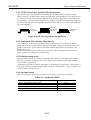
1.5 Consumables
1.5.1 BJ cartridge
Each of the BJ cartridges (Black BJ cartridge "BC-80," Color BJ cartridge "BC-81", or
Photo BJ cartridge "BC-82 photo") used on this printer are supplied as consumables
(sold as BJ cartridge + ink tanks).
1.5.2 Ink tank
The ink tanks below are supplied as consumables (sold as individual ink tank):
BCI-8BK, BCI-8WF for Black BJ cartridge "BC-80"
BCI-8 C, BCI-8 M, BCI-8 Y for Color BJ cartridge "BC-81"
BCI-82PBK photo, BCI-82PC photo, BCI-82PM photo for Photo BJ cartridge "BC-82
photo"
If any of the ink tanks run out of ink, or ideal print quality cannot be obtained by
repeated cleaning, replace the ink tank with a new one. (The recommended
replacement cycle is 6 months after unpacking.) If ideal print quality still cannot be
obtained after replacing the ink tank, replace the BJ cartridge.
The number of pages that can be printed out by each ink tank is as follows:
BCI-8BK:
About 940 sheets by continuous printing of the 1500-character standard pattern
BCI-8WF:
About 1870 sheets by continuous printing of the 1500-character standard pattern
(about 380 sheets by continuous printing of the color printing standard pattern)
BCI-8 C, BCI-8 M, BCI-8 Y:
About 450 sheets by continuous printing of the color printing standard pattern
BCI-82PBK photo, BCI-82PC photo, BCI-82PM photo:
About 390 sheets by continuous printing of the color printing standard pattern
Ink Inlets
BCI-8BK
BCI-8WF
BCI-8C
BCI-8M
BCI-8Y
Figure 2-7 Ink Tanks
2-7
BCI-82PBK Photo
BCI-82PC Photo
BCI-82PM Photo
Part 2: Product Specifications
BJC-8500
2. SPECIFICATIONS
2.1 General Specifications
1. Type
Serial color bubble jet printer for corporate use
2. Paper feeding method
Auto sheet feed (sheet feeder, cassette) and manual feed
3. Resolution
300 × 300/600 × 600/1200 × 600/1200 × 1200 dpi (black/color)
1200 × 600/1200 × 1200 dpi (photo)
4. Printing speed
Burst
HQ mode: 213 cps (10 kHz discharge)
HS mode: 683 cps (8 kHz discharge, 25% printing)
Throughput
Black printing
HQ: 2.7 ppm (600 × 600 dpi, bi-directional, 1 pass)
HS: 4.3 ppm (300 × 300 dpi, bi-directional, 1 pass)
Color printing
HQ: 0.9 ppm (600 × 600 dpi, uni-directional, 2 passes)
HS: 2.1 ppm (300 × 300 dpi, uni-directional, 1 pass)
5. Print width
Max. 322.2 mm (max. print width when A3+ is selected)
6. Line feed speed
Approx. 180ms/line (256/600 inch line feed)
7. Line feed pitch
n/600 inch (Canon extended mode n: programmable)
8. Printing direction
Color: Uni-directional, Black: Bi-directional, Uni-directional
9. Control mode
Canon extended (Native) mode
10. Built-in character
Courier (94 character, 300 dpi)
11. Buffer
Receive buffer Approx. 1 MB
12. Interface
IEEE 1284 compatible bi-directional parallel interface (for Compatibility, Nibble and ECP modes)
RS422 (for Macintosh)
13. Interface cable
Material: AWG28 or larger
Type:
Twisted-pair shielded cable
Length: Up to 2.0 meters (6.6 feet)
2-8
Part 2: Product Specifications
BJC-8500
14. Interface connector
Printer side: Amphenol 57-40360 (or equivalent)
Cable side: Amphenol 57-30360 (or equivalent)
15. Paper feed method
Cassette/sheet feeder/manual feed
Plain paper, color plain paper, high-resolution paper
Sheet feeder/manual feed
Envelopes, OHP film, glossy photo paper, BJ cloth, high-gloss photo film, T-shirt
transfer, banner paper
Manual feed only
Thick paper, BJ cloth
16-1. Cassette stack amounts
Plain paper, color plain paper
High-resolution paper
Max. 250 sheets
Max. 200 sheets
16-2. Sheet feeder stack amounts
Plain paper
High-resolution paper
Envelopes
OHP film
Glossy photo paper
High-gloss photo film
Banner paper
Max. 100 sheets
Max. 80 sheets
Max. 15 sheets
Max. 50 sheets
20 sheets
1 sheet
1 sheet
17. Available paper
Standard paper
Envelopes
Color plain paper
High-resolution paper
Glossy photo paper
High-gloss photo film
OHP film
Cloth
T-shirt transfers
Banner paper
Size:
Weight:
Thickness:
A3+, A3, A4+, A4, A5
64 g/m2 to 105 g/m2 (sheet deer/cassette)
0.25 mm max. (manual feed)
COM#10, DL
Canon bubble jet paper
LC-301
Color BJ high-resolution paper
HR-101
Color BJ glossy photo paper
GP-301
Color BJ high-gloss photo film
HG-201
Color BJ OHP film
CF-102
Color BJ cloth
FS-101
TR-201
BP-101
18. BJ Cartridge
Black BJ Cartridge BC-80
Nozzle
128 nozzles × 2 rows × 3 heads
Ink color
Black, ink optimizer (translucent)
Ink amount
Black: 54ml Ink optimizer: 55ml
Weight
Approx. 164g (Including ink tanks)
Number of pages printable per ink tank
Black
Approx. 940 sheets (continuous printing of 1500-character standard pattern)
Ink optimizer Approx. 1870 sheets (continuous printing of 1500-character standard pattern)
Head life
Approx. 7500 sheets (continuous printing of 1500-character standard pattern)
Approx. 5000 sheets (continuous printing of color printing standard pattern
at 7.5% duty per color)
2-9
Part 2: Product Specifications
BJC-8500
Color BJ Cartridge BC-81
Nozzle
128 nozzles × 2 rows × 3 heads
Ink color
Cyan, magenta, yellow
Ink amount
23.5ml for each color
Weight
Approx. 103g (including ink tanks)
Number of pages printable per ink tank
Approx. 450 sheets (continuous printing of color printing standard
pattern at 7.5% duty per color)
Head life
Approx. 5000 sheets (continuous printing of color printing standard
pattern at 7.5% duty per color)
Photo BJ Cartridge BC-82 Photo
Nozzle
128 nozzles × 2 rows × 3 heads
Ink color
Photo black, photo cyan, photo magenta
Ink amount
23.5ml for each color
Weight
Approx. 112g (including ink tanks)
Number of pages printable per ink tank
Approx. 390 sheets (continuous printing of color printing standard
pattern at 7.5% duty per color)
Head life
Approx. 5000 sheets (continuous printing of color printing standard
pattern at 7.5% duty per color)
19. Acoustic noise level
Approx. 50 dB (sound pressure level according to ISO 9296)
20. Environmental requirements
During operation
Temperature 5 to 35°C
Humidity 10 to 90% (no condensation)
During storage
Temperature 0 to 35°C
Humidity 5 to 90% (no condensation)
21. Power supply
AC 120V/60 Hz, 230V/50 Hz
22. Power consumption
At software power OFF
During standby
During printing
Max. 8 W
Max. 9 W
Max. 67 W
23. External dimensions
604 mm (W) × 584 mm (D) × 440 mm (H)
(with lower cassette attached)
24. Weight
Body
Approx. 25 kg (including lower cassette, BJ cartridges, Ink Tanks)
2-10
Part 2: Product Specifications
BJC-8500
25. Detection functions
Paper-out/Paper jam
Available
BJ cartridge presence
Available
Waste ink amount
Available
Paper size (cassette)
Available
BJ cartridge identification
Available
Ink tank presence
Available
Cover open
Available
Home position
Available*
Ink out
Available
* Though the printer does not have home position sensor, the home position is
detected by the encoder when carriage contacts the right end of the chassis.
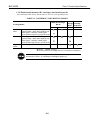
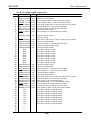
2.2 Paper Specifications
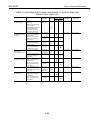
2.2.1 Paper types
TABLE 2-2 PAPER SPECIFICATIONS
Plain Paper
Type
Paper
Class 1 Canon PB (NSK)
Canon PB (NDK)
Canon NP (Kangas)
Canon NP (Neusiedler)
Canon NP (BoiseCascade)
Canon BJ paper LC-301
Class 2 Xerox 4024 (75g/m2)
Xerox 4024 (95g/m2)
Plover Bond
Size
A3, A4, *1A5
A3, A4, *1A5
A3, A4
A3, A4
LTR, LGL
A3, LDR, A4, LTR
LDR, LGL, LTR
LDR, LGL, LTR
LTR
Cassette Sheet Feeder Manual Feed
●
●
●
●
●
●
●
●
●
●
●
●
●
●
●
●
●
●
●
●
●
●
●
●
●
●
●
Special Paper
Type
High-resolution
paper
OHP film
Glossy photo
paper
High-gloss
photo film
Envelopes
BJ cloth
Banner paper
Thick paper
Paper
HR-101
Size
Cassette Sheet Feeder Manual Feed
2
* A3+, A3, LDR, A4, LTR
●
●
●
CF-102
GP-301
A4, LTR
*2A3+, A3, LDR, *2A4+,
A4, *2LTR+, LTR
A3, LDR, A4, LTR
✕
✕
●
●
●
●
✕
*3●
●
241 × 105mm
220 ×110mm
241 × 356mm
210 × 297mm, 216 × 279mm
✕
✕
✕
✕
✕
●
●
✕
●
✕
✕
✕
●
✕
●
HG-201
COM#10 No. 582
DL, PLUS
FS-101
●: Usable
✕: Not usable
* : A5 (vertical):
sheet feeder/manual feed
A5 (horizontal): sheet feeder only
*2: A3+ size is a Canon original size slightly larger (329 × 483 mm) than regular A3 size
Using A3+ size allows you to print out an A3-size page with register marks.
The same applies to LTR+ (228.6 × 337.8 mm) and A4+ size (223.5 × 355.6 mm).
3
* : When HG-201 is fed from the sheet feeder, make sure that the cut corner of the HG-201
is at the top right during vertical feed and at the top left during horizontal feed.
1
2-11
Part 2: Product Specifications
BJC-8500
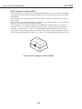
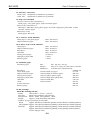
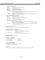
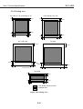
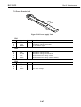
2.2.2 Printing area
A3+, LDR, A3, LTR (horizontal), A4, A5
3mm
LTR (vertical), LGL size
3mm
23mm
23mm
29mm
7mm
3.4mm
3.4mm
29mm
7mm
6.4mm
A4+, LTR+ size
6.4mm
BJ cloth
27.9mm
29mm
25.4mm
27.9mm
29mm
5.08mm
5.88mm (A4+)
5.08mm (LTR+)
20.5mm
6.4mm
Envelope
3mm
23mm
29mm
7mm
6.4mm
6.4mm
: Print Quality Assurance Area
: Printable Area
Figure 2-8 Printing Area
2-12
6.4mm
Part 2: Product Specifications
BJC-8500
2.3 Interface Specifications
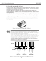
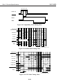
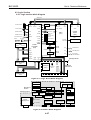
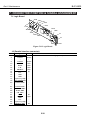
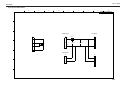
2.3.1 Parallel interface
1. Data Transmission Method
8-bit parallel interface (IEEE1284 compatible)
Bi-directional protocol (supports Compatibility mode/Nibble mode/ECP mode)
Note: The handshake transmission method of DATA STROBE from the host
computer, with ACKNLG signal and BUSY signal from the printer. Reverse
transmission by Nibble and ECP modes.
2. Signal Levels
Input: High +2.0 to +5.25V
Low -0.3 to +0.8V
Output: High +2.4 to +5.25V
Low -0.3 to +0.4V
3. Input/Output Circuits
+5V
DATA1
DATA2
DATA3
DATA4
DATA5
DATA6
DATA7
DATA8
STROBE
36p
2
3
4
5
6
7
8
9
3.3K
3.3K
3.3K
3.3K
3.3K
3.3K
3.3K
3.3K
IFD0
IFD1
IFD2
IFD3
IFD4
IFD5
IFD6
IFD7
6.8V
ZD
1000p
100
1K
1
CENSTB
470p
ACK
BUSY
PError
Select
FAULT
10
11
12
13
32
INIT
31
3.3K
1K
3.3K
3.3K
3.3K
CENACK
CENBUSY
CENPE
CENSELT
CENFALT
1000p
100
3.3K
CENINT
470p
SLCT IN
100
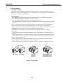
3.3K
36
CENSELIN
470p
100
3.3K
Auto Feed XT 14
CENAFXT
470p
+5V
15
34
390
Peripheral Logic High 18
S-GND
16, 19*30, 33
GND 17
FG
GND
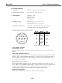
4. Interface Cable
Type Twisted-pair shielded cable
Material
AWG No. 28 or more
Length
Up to 2.0m (6.6 feet)
5. Interface Connectors
Printer side
Amphenol 57-40360 or the equivalent
Cable side
Amphenol 57-30360 or the equivalent
2-13
Part 2: Product Specifications
BJC-8500
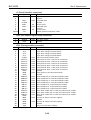
6. Pin Assignments
No.
1
2
3
4
5
6
7
8
9
10
11
12
13
14
15
16
17
18
Signal
Circuit Diagram *5
DATA STROBE
STROBE
DATA1
DATA1
DATA2
DATA2
DATA3
DATA3
DATA4
DATA4
DATA5
DATA5
DATA6
DATA6
DATA7
DATA7
DATA8
DATA8
ACKNLG
ACK
BUSY
BUSY
P.E.
PError
SELECT
Select
4
AUTO FEED XT * Auto Feed XT
N.C. *2
N.C.
GND
GND
GND
GND
Peripheral Logic High *3 Peripheral Logic High
IN/OUT No. Signal
Circuit Diagram *5
1
IN
19 DATA STROBE -RET *
GND
IN/OUT 20 DATA1 -RET *1
GND
IN/OUT 21 DATA2 -RET *1
GND
1
IN/OUT 22 DATA3 -RET *
GND
IN/OUT 23 DATA4 -RET *1
GND
1
IN/OUT 24 DATA5 -RET *
GND
IN/OUT 25 DATA6 -RET *1
GND
IN/OUT 26 DATA7 -RET *1
GND
1
IN/OUT 27 DATA8 -RET *
GND
OUT
28 ACKNLG -RET *1
GND
OUT
29 BUSY -RET *1
GND
1
OUT
30 P.E. -RET *
GND
OUT
31 INIT
INIT
IN
32 FAULT
FAULT
33 GND
GND
N.C.
34 N.C.*2
3
—
35 Peripheral Logic High *
36 SELECT INX *4
SLCT IN
IN/OUT
IN
OUT
IN
Note:
*1. All -RET signals are connected to signal ground (0V).
*2. N.C. means non-connection.
*3. For No. 18 and 35 (Peripheral Logic High), the level is connected to +5.0V at 390Ω.
*4. For No. 14/No. 36, the level is connected to +5.0V at 3.3kW.
*5 Refer to "Part 5: 8.2 Circuit Diagrams LOGIC BOARD 12" (page 5-64).
7. Signals (Compatibility Mode)
Input signals:
1) DATA STROBE
This signal is a strobe signal for reading DATA1 to DATA8.
This signal is high in normal condition, and the signal goes low when the printer
receives data.
The BUSY signal is kept high until this signal changes from low to high.
2) DATA1 to 8
The printer receives data by the DATA STROBE signal.
Each bit of DATA1 to DATA8 must not change until 0.5 µs or more passes after the
DATA STROBE signal's rising edge.
3) INIT
When the specified period of time has passed after the signal changes from high to
low and the signal becomes high again, the printer considers the signal as a input
prime and performs the following:
a) Initialization is performed when the parallel port is selected.
b) Ignores the input prime when the serial port is selected.
4) AUTO FEED XT
In the BJC-8500, this signal is used only as a transmission signal from the
Compatible mode to negotiation mode.
2-14
Part 2: Product Specifications
BJC-8500
5) SELECT INX
In the BJC-8500, this signal is used only as a transmission signal from the
Compatible mode to negotiation mode.
Output Signals:
1) ACKNLG
This signal is a response signal to the DATA STROBE signal.
This signal becomes high when the next DATA STROBE signal is output during the
output of this signal.
2) BUSY
When this signal is high, it means the printer cannot receive data. When it is low,
it means the printer can receive data.
This signal goes high in the following conditions.
• When receiving data
• When receiving buffer is full.
• During initialization
• When replacing BJ cartridge and ink tanks
• During cleaning operation by user
• When in error
• During software on and off
• During the period when the serial port is selected.
3) P.E.
If paper is not fed following paper feeding operation, this signal goes high. The
signal goes low after the RESUME button is pressed.
In the BJC-8500, when the automatic feeding slot select function is valid, the
paper feed operations will be performed from the possible feeding slots, one by one.
This signal goes high when the paper is not fed if this function is set.
4) SELECT
This signal goes high when the parallel port is selected and the printer is ready to
receive data.
5) FAULT
When the error occurs in this printer, this signal goes low. When no error has
occurred in the printer, the signal is high.
In the BJC-8500, this signal goes low when the printer is in error or when the
specific status response is required.
8. Signals (Nibble Mode)
Input signals:
1) DATA STROBE (Host Clk)
In Nibble mode, this signal is always high. The printer does not receive data in this
state.
2) DATA1 to 8 (Data 1 to 8)
Because of the IEEE1284 interface specifications, these signals are not used in
Nibble mode.
2-15
Part 2: Product Specifications
BJC-8500
3) INIT
Because of the IEEE1284 interface specifications, this signal is not used in Nibble
mode.
4) AUTO FEED XT (Host Busy)
The host computer makes this signal low to show it can receive data from the
printer. When the computer receives data from the printer, this signal becomes
high to tell the printer data is being received.
5) SELECT INX (1284 Active)
This signal is high at the beginning of negotiation phase, and is always high in
Nibble mode. This indicates that the printer is operating in bi-directional mode.
After completing Nibble mode, this signal becomes low and shifts to the
termination phase.
Output Signals:
1) ACKNLG (Ptr Clk)
By lowering this signal, the printer tells the computer that data has been output.
When AUTO FEED XT (Host Busy) signal from the host computer indicating data is
being received is raised to high, ACKNLG signal responds by becoming high. This
signal becomes low twice in order to transmit 1 byte data.
2) BUSY (Ptr Busy)
This signal outputs data to the host computer. For byte data, the third bit of data
is output first, followed by the seventh bit of data.
3) P.E. (Ack Data Req)
This signal outputs data to the host computer. For byte data, the second bit of
data is output first, followed by the sixth bit of data.
4) SELECT (Xflag)
This signal outputs data to the host computer. For byte data, the first bit of data is
output first, followed by the fifth bit of data.
5) FAULT (DataAvail)
This signal outputs data to the host computer. For byte data, the 0 bit of data is
output first, followed by the fourth bit of data.
9. Signals (ECP Mode)
Input signals:
1) DATA STROBE (Host Clk)
This signal handshakes with the BUSY (PeriphAck) signal to transmit data from the
computer to the printer during the forward phase. When this signal is low, it
indicates that data has been sent to DATA1 to 8 (Data 1 to 8).
When BUSY (PeriphAck) signal is raised, DATA STROBE signal responds by
becoming high. In reverse phase, this signal is always high.
2) DATA1 to 8 (Data 1 to 8)
When the host computer outputs data during forward phase, DATA signal is an
input signal. When the printer outputs data to the host computer during reverse
phase, DATA signal is an output signal.
2-16
Part 2: Product Specifications
BJC-8500
3) INIT (ReverseRequest)
This signal is set to low to perform a recovery process of the data sent from the
host computer during the forward phase. When this happens, INIT signal becomes
high, responding to the falling edge of the P.E. (Ack Reverse) signal. INIT signal is
lowered when the forward phase idle is switched to the reverse phase (data to be
sent from the printer to the host computer). The low signal indicates that it is in
reverse phase. When the reverse phase is switched to forward phase, INIT signal is
raised to high.
4) AUTO FEED XT (Host Ack)
During the forward phase, the data on the data bus is received as data. This signal
handshakes with th ACKNLG (PeriphClk) signal to receive data from the printer to
the computer during the reverse phase.
This signal is lowered if data can be received from the printer.
This signal is raised to high when data is received.
5) SELECT INX (1284 Active)
This signal is high at the beginning of negotiation phase and is always high in ECP
mode, indicating that the printer is operating in bi-directional mode. After
completing the ECP mode, SELECT INX signal goes low, moving to termination
phase.
Output Signals:
1) ACKNLG (Periph Clk)
This signal is always high during the forward phase. During the reverse phase,
ACKNLG signal is low to tell the host computer that data has been output on the
data bus. The ACKNLG signal goes high in response to the host computer's high
AUTO FEED XT (Host Ack) signal to indicate data reception from the host.
2) BUSY (Periph Ack)
During the forward phase, BUSY signal is low if the printer can receive data. Once
the data has been received, BUSY becomes high. During the reverse phase in the
BJC-8500, this signal is always high as it only supports the data sent from the
printer to the host computer.
3) P.E. (Ack Reverse)
This signal is always high during the forward phase, and is always low during the
reverse phase.
P.E. signal is lowered in response to the host computer's low INIT (Reverse Request)
signal to confirm the request to transfer from forward phase to reverse phase.
P.E. signal is raised in response to the host computer's high INIT (Reverse Request)
signal to confirm the request to transfer from reverse phase to forward phase.
4) SELECT (Xflag)
This signal is always high during ECP mode.
5) FAULT (PeriphRequest)
In the BJC-8500, if there is still data to be transferred to the host computer during
the forward phase, this signal is lowered to request reverse phase.
In the BJC-8500, FAULT signal is raised high in response to the AUTO FEED XT's
(Host Ack) low signal after completing all necessary data transmission.
2-17
Part 2: Product Specifications
BJC-8500
500ns 500ns 500ns
min.
min.
min.
DATA 1-8
STROBE
BUSY
ACK
4.0µs
Figure 2-9 Compatibility Mode Timing Chart
1284 Active
Ack Data Req
Bit2
Bit6
Bit3
Bit7
Bit0
Bit4
Bit1
Bit5
Host Busy
Host Clk
Ptr Clk
Ptr Busy
Printer BUSY Status
Data Avail
Ptr
Host
With data
Xflag
Nibble mode
Support
TP
TP
TP
*TP of the BJC-8500: 0.5µsec
Figure 2-10 Nibble Mode Timing Chart
1284 Active
Ack Reverse
Data (1-8)
0001 0000
Host Ack
Byte0
Byte1
nCmd
nCmd
Host Clk
Periph Clk
Periph Ack
Periph Request
Xflag
ECP mode Support
TP
TP
TP
TP
*TP of the BJC-8500: 0.5µsec
Figure 2-11 ECP Mode Timing Chart
2-18
Part 2: Product Specifications
BJC-8500
2.3.2 Serial interface
1. Interface
RS-422-compatible serial interface.
2. Data transfer speed
57.6 (default), 444, 888 kbit/s
3. Data format
Start bit: 1 bit
Data: 8 bits
Stop bit: 1 bit
Parity: None
4. Signal polarity
MARK (logical "1"): -3V to -12V
SPACE (logical "0"): +3V to +12V
5. Interface connectors
On printer: Female 8-pin mini-DIN connector
On cable: Male 8-pin mini-DIN connector
6. Input/output signals and pin layout
8
7
6
4
5
2
Pin No.
Signal
I/O
1
SCLK
OUT
2
N.C.*1
3
OUT
TXD4
S-GND
5
IN
RXD6
OUT
TXD+
7
N.C.
8
IN
RXD+
Shield
PG
*1. N.C. means no connection
3
1
7. Description of signals
SCLK (signal clock)
This pin outputs a sync clock when data transfer speed is set to 442.2 and 884.4
kbit/s.
TXD-/TXD+ (transmitted data)
Output signals TXD- and TXD+ are the differential signals for sending data from the
printer. TXD- is in the MARK state (logical "1") when no data is being sent; TXD+ is
in the SPACE state (logical "0"). These signals are used to send the printer status,
etc., to the host computer.
RXD-/RXD+ (received data)
Input signals RXD- and RXD+ are the differential signals for the printer to receive
data. RXD- is in the MARK state (logical "1") when no data is being sent; RXD+ is in
the SPACE state (logical "0"). These signals are used to receive the control
commands and print data sent from the host computer to the printer.
PG (protection ground)
PG is a low-impedance ground for the interface cable shielding.
2-19
Part 2: Product Specifications
BJC-8500
This page intentionally left blank
2-20
Part 3
OPERATING
INSTRUCTIONS
Page
3- 1
3- 1
3- 3
3- 4
3 -10
3 -11
3 -13
3 -15
3 -15
3 -16
3 -17
3 -17
3 -18
3 -19
3 -23
3 -25
3 -27
1. PRINTER SETUP
1.1 Unpacking
1.2 Installation Space
1.3 Installation Procedure
1.4 Turning the Printer ON/OFF
1.5 Paper Settings
1.6 Names and Functions of Parts
2. TRANSPORTING THE PRINTER
2.1 Transporting the Printer
2.2 Capping Lock/Unlock
3. PRINTER SERVICING FUNCTIONS
3.1 Error Indications
3.2 Warning Display
3.3 Function Settings
3.4 Control Buttons
3.5 Self Test Print (Nozzle Check Pattern)
3.6 EEPROM
Part 3: Operating Instructions
BJC-8500
1. PRINTER SETUP
1.1 Unpacking
After unpacking the printer, check that you have the following:
Instruction Manual Container SB-80
Packing
Flap
Carton
Flapper Unit
Packing
Upper Cassette
Packing
Power Cord
Polyethylene Sheet
Carton
BJ Cartridges
Paper Output Tray
Packing
Reinforcer
Instruction Manual &
Printer Driver, etc.
Ink Tanks
Packing
Packing
Packing
Packing
Tape
Reinforcer
Tape
Tape
Platen Retainer Sheet
Tape
Figure 3-1 Packing (1)
3-1
Carton
Part 3: Operating Instructions
BJC-8500
Paper Output Tray
Polyethylene Sheet
Lower Cassette
Packing
Packing
Tapes
Packing
Carton
Packing
Tapes
Figure 3-2 Packing (2): Lower Cassette
3-2
Part 3: Operating Instructions
BJC-8500
1.2 Installation Space
Install the printer with the clearances given below for the printer to be operated
efficiently.
When the carriage moves to the left and right, the printer may generate substantial
vibration. Do not install the printer at a location where it is easily affected by vibration.
The minimum amount of space required when installing the printer is shown below.
Approx. 588 mm
Ap
pro
x.
60
3m
m
.
rox
7
76
mm
p
Ap
Figure 3-3 Installation Space
Use the printer within the following temperature and humidity ranges:
Ambient temperature: 5°C to 35°C
Relative humidity: 10% to 90% (no condensation)
Do not install the printer in places where it is exposed to direct sunlight or
near a heater, air conditioner, or in a car where the temperature rises
suddenly.
Do not install the printer in dusty places or where it is subjected to salty
wind.
Do not place it near a television set, speaker, or other devices which
generate magnetic fields.
Install the printer on a flat sturdy surface.
The printer is heavy. It weights about 25 kg. Make sure that the surface
where the printer is installed can bear its weight.
3-3
Part 3: Operating Instructions
BJC-8500
1.3 Installation Procedure
Install the printer as follows.
1.3.1 Connecting the interface cable
1) Make sure that the printer and host computer are OFF.
2) Plug the interface cable into the printer interface connector. Secure the cable with
connector clips.
3) Connect the other end of the interface cable to the host computer and fix it securely.
1. Connect the interface cable to the printer.
Macintosh
2. Connect the interface cable to the computer.
Windows
Machine
Macintosh
Windows
Machine
Figure 3-4 Connecting the Interface Cable
1.3.2 Connecting the power supply
1) Connect the power cord plug to the printer, and then the other end of the power
cord to the power outlet. (q and w in Figure 3-5 below)
2) Press the printer POWER button (e in Figure 3-5 below). The printer buzzer
sounds four times, and the POWER indicator and ERROR indicator light.
3) Open the printer’s top cover. The carriage moves to the left edge, allowing you to
install the BJ cartridges.
2 Connect the other end of the
power cord to the power outlet.
3 Press the POWER button.
1 Connect the power cord
plug to the printer.
Figure 3-5 Connecting the Power Supply
3-4
Part 3: Operating Instructions
BJC-8500
1.3.3 Installing BJ cartridges
1) Removing the protective cap from the BJ cartridge
Remove the BJ cartridge from the aluminum bag, and remove the protective cap
from the nozzles.
Protective Cap
Figure 3-6 Removing the Protective Cap
Do not reuse head caps that have been removed once. If they are reused,
the head may become clogged with foreign matter, or colors of ink may be
mixed.
Gently remove the protective cap from the print head, taking care not to
touch the print head directly with your hand or fingers.
Poor printing may be caused by scratches on the print head or any foreign
matter adhered to it.
After removing the cap, do not shake the BJ cartridge. Ink could splatter
out if you do.
2) Installing the BJ cartridge
Open the printer’s top cover, and press the BJ cartridge REPLACE button. The
buzzer sounds once, and the carriage moves to the BJ cartridge replacement
position. Install the BJ cartridge on the carriage. Install Color BJ cartridge BC-81
on the holder on the right, and install Black BJ cartridge BC-80 (or Photo BJ
cartridge BC-82 Photo) on the holder on the left.
After installing the BJ cartridges, either press the BJ cartridge REPLACE button, or
close the top cover. The buzzer sounds once, and after warming up for about 40
seconds, the carriage returns to the capping position (right edge of printer body).
Black BJ Cartridge
BC-80 or
Photo BJ Cartridge
BC-82 Photo
BJ Cartridge
REPLACE Button
Color BJ Cartridge BC-81
*
* This illustration shows Black BJ cartridge BC-80.
Figure 3-7 Installing BJ Cartridges
3-5
Part 3: Operating Instructions
BJC-8500
3) Adjusting the print head position
As two print heads are installed on the printer, differences sometimes occur in the dot
placement of ejected ink, and high-grade printing sometimes cannot be obtained
depending on the individual characteristics specific to each print head and installation
state. To eliminate these differences, the mutual positions of the print heads must be
adjusted as follows after the Canon printer driver has been installed.
Procedure
1) Load two or more sheets of A4-size plain paper in the sheet feeder.
2) Select "Test Prints" under Maintenance Sheet in the printer driver, and print the
head position adjustment pattern (Figure 3-8 Checking the Position of the Print Head
(1)).
3) Visually check the printed pattern, and select the optimum pattern at each of A
(vertical direction between two heads -1 to +1; one unit = 1/600 inch), B
(horizontal direction between two heads -7 to +7; one unit = 1/600 inch) and C
(bi-direction of one head -7 to +7; one unit = 1/1200 inch).
4) Follow the instructions on Maintenance Sheet in the printer driver, and print the
high-resolution adjustment pattern (Figure 3-9 Checking the Position of the Print Head
(2) (page 3-7)) .
5) Visually check the printed patterns, and select the optimum pattern at D
(horizontal direction between two heads -1 to +1; one unit = 1/1200 inch).
6) Follow the instructions on Maintenance Sheet in the printer driver, and end the
print head position adjustment.
7) The dot placement of the ink after adjustment can be checked by outputting a test
print (nozzle check pattern).
Figure 3-8 Checking the Position of the Print Head (1)
3-6
Part 3: Operating Instructions
BJC-8500
Figure 3-9 Checking the Position of the Print Head (2)
3-7
Part 3: Operating Instructions
BJC-8500
1.3.4 Replacing ink tanks
Replace the ink tank as follows.
1) Ink tank replacement criteria
Replace the ink tank in any of the following cases: "ink-out" detection indicates that
the ink tank has run out of ink, or when cleaning does not improve print quality.
(Generally, the ink tank should be replaced about six months after it is removed
from its package.)
2) Removing the ink tank
Press the BJ cartridge REPLACE button to move the carriage to the BJ cartridge
replacement position (left edge of printer).
As shown in Figure 3-10 Replacing Ink Tanks, lift up the section marked with the arrow
at the front of the ink tank, and remove the ink tank from the BJ cartridge. Ink
adheres to and around the ink tank’s ink outlet, so handle the ink tank carefully.
3) Installing the ink tank
Take out the ink tank from its box and open the package. Remove the ink outlet's
protective cap as shown in Figure 3-11 How to Remove the Ink Tank Protective Cap, and
install the ink tank in the printer by following the removal procedure in reverse.
BJ Cartridge REPLACE Button
Figure 3-10 Replacing Ink Tanks
After installing the ink tank, press the BJ cartridge REPLACE button or close the top
cover to return the carriage to the capping position (right edge of printer). Then,
cleaning C is performed automatically. (See "TABLE 4-7 CLEANING EXECUTION
CONDITIONS, CLEANING TIME AND INK SUCTION AMOUNTS" (page 4-25).)
Figure 3-11 How to Remove the Ink Tank Protective Cap
3-8
Part 3: Operating Instructions
BJC-8500
1.3.5 BJ cartridge container SB-80
The printer is supplied with BJ cartridge container SB-80 for storing Black BJ
cartridge BC-80, Color BJ cartridge BC-81 or Photo BJ cartridge BC-82 Photo.
When Black BJ cartridge BC-80 is installed in the printer, store the Photo BJ
cartridge BC-82 Photo in the BJ cartridge container. Alternately, when Photo BJ
cartridge BC-82 Photo is installed in the printer, store Black BJ cartridge BC-80 in
the BJ cartridge container.
When you store the Black BJ cartridge BC-80 or the Photo BJ cartridge
BC-82 Photo in the BJ cartridge container, store the cartridges with the
ink tanks installed (except when transporting the printer: see "Part 3: 2.1
Transporting the Printer" (page 3-15)).
Also take care when inserting BJ cartridges, making sure that they are
inserted in the correct direction.
Do not shake or drop the container. Otherwise, ink may leak.
Press here.
Container SB-80
Contains either
Photo BJ cartridge BC-82 Photo
or Color BJ cartridge BC-81.
Contains only
Black BJ cartridge BC-80.
Figure 3-12 BJ Cartridge Container SB-80
3-9
Part 3: Operating Instructions
BJC-8500
1.4 Turning the Printer ON/OFF
1.4.1 Turning the printer on
With the printer connected to a power source, press the POWER button to turn ON
the printer. When the printer turns ON, the beeper sounds once and initializing
operations are executed.
If a BJ cartridge is not installed, the "No BJ cartridge" error occurs ("Part 3: 3.1.1
Operator call" (page 3-17)).
If a BJ cartridge is installed, the POWER indicator will light to indicate that the
printer is ready.
When the power is first turned ON from a hardware ON state, the printer checks for
ink-out; if "ink-out" is judged cleaning A is automatically carried out (for details, see
"Part 4: TABLE 4-7 CLEANING EXECUTION CONDITIONS, CLEANING TIME AND INK
SUCTION AMOUNTS" (page 4-25)). Cleaning A takes about two minutes. During
cleaning, the POWER indicator flashes to indicate that cleaning is in progress.
1.4.2 Turning the printer off
To turn the printer OFF, press the POWER button.
When the print is turned OFF, the power OFF sequence for capping the BJ cartridges
is executed, and the POWER indicator blinks to indicate that this sequence is being
executed. When this sequence ends, the POWER indicator goes out.
Make sure that the POWER indicator is OFF before disconnecting the power cord.
Never turn OFF the printer by disconnecting the power cord without first
pressing the POWER button. Otherwise, the printer turns OFF before it
can cap the BJ cartridges. If the BJ cartridges are not capped, the ink
may leak or dry in the nozzles, causing defective printing later on.
If the POWER button is pressed to the turn the printer OFF during printing, printing
is immediately interrupted and printer operation ends.
If the POWER button is pressed to turn the printer OFF during replacement of a BJ
cartridge or ink tank, the carriage returns to the home position, and printer operation
ends.
If the POWER button is pressed to turn the printer OFF during cleaning, cleaning is
interrupted and printer operation ends.
If the POWER button is pressed to turn the printer OFF while the cover is open,
printer operation ends immediately.
Figure 3-13 Precautions When Turning the Printer OFF
3-10
Part 3: Operating Instructions
BJC-8500
1.5 Paper Settings
For optimum printing, selectively use the automatic pick-up mechanism using the
cassette and sheet feeder, and manual feed for feeding paper from the rear of the
printer according to the type of printing paper you are using. This printer does not
have a paper thickness adjustment lever as the distance between sheets is
automatically adjusted to suit the type of paper. Paper support is performed by
sliding/drawing out the cassette's paper output tray and tray extension, and the sheet
feeder's paper guide and paper rest.
Paper Rest
Paper Guide
Tray Extension
Paper Output Tray
Figure 3-14 Paper Settings
3-11
Part 3: Operating Instructions
BJC-8500
TABLE 3-1 PRINTER PAPER SETTINGS
Media
Plain Paper
Paper Name
Ream weight
64 to 90g/m2
Color BJ Plain LC-301
Paper
Color BJ HighHR-101
Resolution Paper
Glossy Photo
GP-301
Paper
High-Gloss
HG-201
Photo Film
Color BJ
CF-102
Transparencies
Fabric Sheets FS-101
Envelopes
COM# 10 No.582
DL PLUS
Envelopes
—
Thick paper
Banner paper*2 Banner paper
BP-101
T-shirt Transfer TR-201
A3/A4
Auto
A3+/A3/A4
Auto
A3+/A3/A4+/A4
Auto
Stack Amounts
Sheet Feeder Cassette
10 mm
25 mm
(100 sheets) (250 sheets)
10 mm
25 mm
(100 sheets) (250 sheets)
10 mm
25 mm
(80 sheets)
(200 sheets)
20 sheets
—
A3/A4
Auto
*1 1 sheet
—
A4
Auto *4
50 sheets
—
241×356mm
241 (H)×105 (V) mm
220 (H)×110 (V) mm
91 to 105g/m2
210×297/216×279
Manual
Auto
Auto
Manual
Auto
—
15 sheets
15 sheets
—
*3
—
—
—
—
—
Auto
1 sheet
—
Size
Feed Method
A3/A4/A5 Vertical Auto
*1 When HG-201 is fed from the sheet feeder, make sure that the cut corner of the HG201 is at the top right during vertical feed and at the top left during horizontal feed.
*2 When banner paper is used, adjust the paper size on the flapper unit to B5, and draw
out the paper output tray.
*3 Load only the leading edge on the sheet feeder.
*4 Place a sheet of plain paper at the bottom.
Paper sizes:
Automatic: Vertical 100 to 355.6mm × Horizontal 100 to 241.3 mm.
Manual: Vertical 150 to 297mm × Horizontal 150 to 241.3 mm.
Ream weight:
Automatic pick-up: 64 to 90 g/m2.
Manual: 0.25 mm thick or less.
3-12
Part 3: Operating Instructions
BJC-8500
1.6 Names and Functions of Parts
This section describes the names of the parts of the printer and their functions.
q
Front of Printer
w
r
e
!1
!3
!2
!4
t
POWER
y
ERROR
RESUME
u
i
Control Panel Section
o
!0
Figure 3-15 Names and Functions of Parts (1)
Front of Printer
q Paper Rest:
w
e
r
t
y
u
i
!0
Supports the paper straight in the sheet feeder. Pull out this
support for use.
Sheet Feeder:
Load sheets of paper into the feeder. The number of sheets that
can be loaded varies according to the type of printing paper used.
Paper Guide:
Adjust the paper guide to the left edge of paper by lightly pulling it
across. This keeps the paper feeding straight.
Guide:
Set this guide upright when printing on envelopes.
Top Cover:
Open this cover to replace the BJ cartridges or ink tanks, or to
remove jammed paper.
Flapper Unit:
This unit sends printed paper to the paper output tray. This unit
prevents ink smearing caused by output of printed paper before the
ink on the previous paper has dried.
Flapper:
This part receives paper that is currently being printed. It holds
the paper until printing is finished, and ejects the paper onto the
paper output tray. Slide the left side of the flapper to adjust the
width of the flapper to the width of the paper being printed (B5 to
A3+).
Paper Output Tray/o Tray Extension: Printed paper is output here. If necessary,
draw out these trays for use.
Cassette:
This cassette accommodates up to 250 sheets of plain paper or up
to 200 sheets of high-resolution paper for printing.
An optional cassette (lower cassette) can also be attached.
3-13
Part 3: Operating Instructions
BJC-8500
Control Panel Section
!1 POWER Button:
Turns the printer ON and OFF.
!2 POWER Indicator: Indicates whether the printer is ON or OFF. This indicator blinks
when print data is received, when the cover is open, or when
cleaning is in progress.
!3 ERROR Indicator: When an error occurs, the buzzer sounds, and the ERROR
indicator either lights or blinks. In the case of a service call, the
number of times that this indicator blinks indicates the type of
error.
!4 RESUME Button: When a paper jam or other trouble occurs, press this button to
reset the printer. This button is also used for manual cleaning.
To start manual cleaning, hold this button down until the buzzer
sounds once then release the button.
Inside of Printer
Rear of Printer
!5
!6
@0
!7
!8
!9
Figure 3-16 Names and Functions of Parts (2)
Inside of Printer
!5 BJ Cartridge REPLACE Button: Pressing this button moves the carriage to the home
position (right edge of printer) from the cartridge replacement
position (left edge of printer), or the opposite operation is carried
out.
Rear of Printer
!6 Serial Interface Connector: For connecting the printer to the serial port on a
Macintosh via the serial interface cable.
!7 Parallel Interface Connector: For connecting the printer to the parallel port on a
Windows machine via the parallel interface cable.
!8 Manual Feed Inlet: Feed paper here when manually printing paper. When manually
inserting paper, make sure that you hold it lightly and that it is
inserted straight.
!9 Back Cover:
Open this cover to remove jammed paper if a paper jam occurs
during printing of paper picked up from the cassette.
@0 Power Cord Connector: Connect the power cord (supplied) to this connector.
3-14
Part 3: Operating Instructions
BJC-8500
2. TRANSPORTING THE PRINTER
Before service personnel or users carry or transport the printer, remove the ink tanks
from the printer, and perform cleaning and capping. This prevents defective printing
caused by ink leakage and ink drying in the BJ cartridge nozzles.
When Black BJ cartridge BC-80 and Photo BJ cartridge BC-82 Photo are used
selectively, store the BJ cartridge that is not installed in the printer in BJ cartridge
container SB-80.
2.1 Transporting the Printer
(The following description assumes that Black BJ cartridge BC-80 and Color BJ
cartridge BC-81 are installed.)
Follow the procedure below to pack the printer to prevent ink leakage and protect the
BJ cartridges.
Container SB-80
Figure 3-17 Transporting the Printer
1) Open the top cover with the printer turned ON, and press the BJ Cartridge REPLACE
button to move the carriage to the BJ cartridge replacement position (left edge of printer).
2) Remove all ink tanks.
3) Wrap each ink tank individually in cling-wrap film, and insert them all in a vinyl bag.
4) Close the top cover. (Pressing the BJ Cartridge REPLACE button is also possible.)
5) The "no ink tank" error is displayed. (See "Part 3: TABLE 3-2 OPERATOR CALL" (page 3-17).)
6) Turn the printer OFF. (Note below)
7) The carriage moves to the right edge of the printer, and any ink remaining in the nozzles
is sucked out (cleaning E is executed). (For details, see "Part 4: TABLE 4-7 CLEANING
EXECUTION CONDITIONS, CLEANING TIME AND INK SUCTION AMOUNTS" (page 4-25).)
8) Disconnect the power cord and interface cable.
9) Close the top cover if open, and pack the printer with the packing materials that it was
originally packed in. If these packing materials are no longer available, pack the
printer using a sufficient amount of packing.
10) Remove the cassette, paper output tray, and flapper unit, and pack them with the
packing materials that they were originally packed in. If these packing materials are no
longer available, pack the printer using a sufficient amount of packing.
If the lower cassette is used, pack it separately from the printer body.
11) Insert Photo BJ cartridge BC-82 Photo in storage container SB-80. (Also, carry out
step 3) above for the ink tank.)
(Note) Never turn OFF the printer by disconnecting the power cord without first pressing the
POWER button. Otherwise, the printer turns OFF before it can cap the BJ cartridges.
If the BJ cartridges are not capped, ink may leak or dry in the nozzles, causing
defective printing later on. (The same applies when the power cord for a power supply
shared with the personal computer is disconnected. Refer to "Part 1: 2.3.6 Ink
leakage/ink dry-up precautions" (page 1-12).)
3-15
Part 3: Operating Instructions
BJC-8500
2.2 Capping Lock/Unlock
When packing the printer, open the top cover, and make sure that the carriage is locked
(the carriage does not move from the home position by moving to the left or right) by the
carriage lock pin on the purge unit at the home position (right edge of printer).
Top Cover
Main Cover
Figure 3-18 Capping Lock
If the carriage is not locked, you can perform capping as follows. Remove the main cover
(refer to Figure 3-18 Capping Lock), insert a regular screwdriver into the groove on the
purge motor shaft and turn it clockwise to raise the carriage lock pin. If the screwdriver
is further turned clockwise, the carriage lock pin is lowered to unlock capping.
Purge Motor
Figure 3-19 Capping Lock/Unlock
The purge motor is very hot immediately after repeated printing or
cleaning. Take care not to touch the purge motor directly with bare hands
after these operations (refer to "Part 1: 2.3.4 Purge motor" (page 1-10)).
3-16
Part 3: Operating Instructions
BJC-8500
3. PRINTER SERVICING FUNCTIONS
3.1 Error Indications
The printer informs the operator of an error status by the ERROR indicator and
sounding of a buzzer.
There are two types of error status: operator calls which are recoverable by the user,
and service calls which are unrecoverable by the user. In either case, the error status
is judged by the number of times that the buzzer sounds and the state of the ERROR
indicator. For an operator call, the ERROR indicator lights, and for a service call, the
ERROR indicator blinks repeatedly for a fixed number of times depending on the cause
of the error.
POWER
ERROR
RESUME
Figure 3-20 Control Panel
3.1.1 Operator call
TABLE 3-2 OPERATOR CALL
[Recoverable by users]
Error Condition
ERROR Indicator
Paper pick-up error/paper jam error
Lights
"Ink-out" error*1/"No ink tank" error
↓
"(No) BJ cartridge" error
↓
2
Waste ink warning*
↓
Beeper
2 times
3 times
4 times
5 times
User Remedy
Load paper. Remove jammed paper.
Replace (install) ink tank.
Replace (install) BJ cartridge.
Press the RESUME button.
*1: The status reply display on the host computer differs depending on the type of ink
used.
2
* : If you continue to use the printer after pressing the RESUME button to cancel the
error, the waste ink full error (service call) is generated.
When the bi-directional interface (nibble mode or ECP mode) is enabled, an "operator
call message in ECP mode (except for paper pick-up error/paper jam error)" is
displayed on the screen of the host computer via the BJC-8500 printer driver. If the
error is not recovered by following the remedy displayed on screen, an error other
than that displayed on screen may have occurred. If this happens, remedy the
trouble by following the description in "Part 5: 6 TROUBLESHOOTING" (page 5-12).
3-17
Part 3: Operating Instructions
BJC-8500
3.1.2 Service call
TABLE 3-3 SERVICE CALL
[Unrecoverable by users]
Error Condition
Carriage error
HP sense error
Purge error
Sheet feeder error
Waste ink full error
BJ cartridge temperature
rise error
EEPROM error
* Other hardware errors
( 1)
ERROR Indicator Beeper Description
2 blinks repeated 6 times Carriage cannot be controlled.
3 blinks repeated
↓
Home position cannot be detected.
4 blinks repeated
↓
The purge unit cannot be initialized.
5 blinks repeated
↓
The sheet feed roller cannot be initialized.
7 blinks repeated
↓
The waste ink level has exceeded the
preset level.
8 blinks repeated
↓
The BJ cartridge has risen above the
preset temperature.
9 blinks repeated
↓
An error occurred during EEPROM
writing.
13 blinks repeated
↓
An error other than the above occurred.
*1: Sometimes errors are not displayed normally.
When the bi-directional interface (nibble mode or ECP mode) is enabled, a "service call
message" is displayed on the screen of the host computer via the BJC-8500 Canon
printer driver.
When a service call occurs, remedy the trouble by following the description in "Part 5:
6 TROUBLESHOOTING" (page 5-12).
3.2 Warning Display
The printer notifies the operator of warning states on the host computer’s screen (not
on the control panel).
BJ Cartridges do not match warning
In the following cases the status monitor displays a warning, cancels printing, and
prompts the user to replace the BJ cartridge or change the printer driver settings:
When Black BJ cartridge BC-80 is installed, and printing is started with the BJ
Cartridge selected to Photo/Color in the printer driver dialog box "Main."
When the Photo BJ cartridge BC-82 Photo is installed, and printing is started with
the BJ Cartridge selected to Black/Color in the printer driver dialog box "Main."
(For details, see Figure 3-21 BJ Cartridges do not Match Warning (Sample))
Figure 3-21 BJ Cartridges do not Match Warning (Sample)
3-18
Part 3: Operating Instructions
BJC-8500
3.3 Function Settings
This printer does not have a function selector for setting functions. The printer drivers
for Macintosh/Windows machines are used to set the various functions.
3.3.1 Maintenance settable items
The printer driver "Maintenance" can be used to set the following items:
1) Print Head Cleaning
Specifies cleaning (all colors, black, color), head refreshing and ink tank.
2) Test Prints
Sets and checks printing of nozzle check pattern and head position adjustment.
3) Power (OFF)
4) Custom Setting
5) Start Status monitor
In Windows, when you select the [Custom Setting] button ([Settings] on the
Macintosh), you can select the "Set printer to ECP mode" (Only in Windows) and
"Pause Page" setup items.
Figure 3-22 Windows 95/98 Printer Driver Maintenance Sheet (Sample)
3-19
Part 3: Operating Instructions
BJC-8500
Figure 3-23 Macintosh Printer Driver Utility Sheet (Sample)
3-20
Part 3: Operating Instructions
BJC-8500
3.3.2 Custom setting
The printer driver has a custom setting dialog box for hidden utility functions. This
dialog box is for servicing only and dealing with claims on the market. It is not
disclosed the user.
(1) Operation Procedure
In Windows:
• Select the [Custom Setting] button in Maintenance on the printer driver. You can
select the "Set printer to ECP mode" and "Pause page" setup items ➝ disclosed the
user.
• If you select the [Custom Setting] button with the [Shift] key held down, you can
select all five setup items in (2) below.
On a Macintosh:
• Select the [Settings] button in Utility on the printer driver. You can select the
"Pause Between Pages" setup item➝ disclosed the user.
• If you select the [Settings] button with the [Shift] key held down, you can select
four setup items (excluding "Set printer to ECP mode") in (2) below.
(2) Setup Items (underline indicates default; ON=
, OFF=
)
• Set printer to ECP mode (ON/OFF)
Sets the printer interface to ECP.
• Pause Page (ON/OFF)
When pages containing high-density images are printed continuously, the
preceding page may become smudged by the following page if sufficient drying time
is not allowed. In such circumstances, set whether or not to pause before
outputting pages.
• Cleaning after cartridge replacement (ON/OFF)
To reduce ink consumption, set not to perform cleaning when the head (BJ
cartridge) is replaced.
• Economy Cleaning (ON/OFF)
To reduce ink consumption, set not to perform cleaning at the first software ON
after a hardware ON and not to perform timer cleaning.
• Display ink low warning (ON/OFF)
Set not to display the ink low warning (Disabling "ink-out" detection) to prevent the
ink sensors from malfunctioning.
3-21
Part 3: Operating Instructions
BJC-8500
Windows 95/98
Macintosh
Figure 3-24 Special Settings (Sample)
3-22
Part 3: Operating Instructions
BJC-8500
3.4 Control Buttons
This printer has two control buttons, the RESUME button and POWER button. These
control buttons are used to perform cleaning the BJ cartridges or for setting service
mode items.
3.4.1 Cleaning the BJ cartridges
If the printer image is blurred or a print defect occurs, such as a white streak, print a
test pattern to see whether or not the BJ cartridge is clogged with ink. If nozzles are
clogged with ink, carry out the procedure below to clean the BJ cartridge and clear
the nozzles.
In addition to cleaning by online operation from the printer driver, this printer also
supports manual cleaning by pressing the RESUME button on the control panel.
Note, however, that when manual cleaning on the control panel is performed, both of
the BJ cartridges installed on the printer are cleaned. (Cleaning of only one head or
cleaning of each individual color head is possible only from the printer driver's
maintenance window. For details, see "Part 4: TABLE 4-7 CLEANING EXECUTION
CONDITIONS, CLEANING TIME AND INK SUCTION AMOUNTS" (page 4-25).
Manual cleaning on the control panel
1) When the printer is turned ON, hold down the RESUME button until the beeper
sounds once.
2) The POWER indicator blinks. (Paper is ejected when the printer contains paper.)
3) The two BJ cartridges installed on the printer are cleaned.
4) When cleaning is finished, the POWER indicator lights.
Manual cleaning is performed cyclically in order F, B, D, F, B, D and so forth.
(However, note that if 10 minutes has elapsed since the previous cleaning operation,
manual cleaning is canceled, and the next manual cleaning operation is started from
F.)
3-23
Part 3: Operating Instructions
BJC-8500
3.4.2 Service mode
Operating the control buttons (RESUME button and POWER button) set the printer to
the service mode.
The following table shows the functions available in the service mode. (print in the
service mode can be executed only when paper is fed in the sheet feeder. The service
mode when connecting to the host computer is not guaranteed.)
q Press the RESUME button five times in a software power OFF state at an interval
of less than 3 seconds, and immediately hold down the POWER button. The
POWER indicator starts to blink.
w When the buzzer has sounded six times, release the POWER button. (You may
keep the POWER button held down as the buzzer sounds only six times.) This sets
the service mode, initialization is executed. (This is the service mode selection
standby state.)
e When initialization ends (POWER indicator stops blinking and lights), select the
desired service mode by pressing the RESUME button for the necessary number of
times (see Table 3-4 SERVICE MODE). The buzzer sounds each time you press the
RESUME button.
r Press the POWER button. The buzzer sounds, and the operation of the selected
service mode is executed. After the operation has been executed, the printer
returns to the service mode selection standby state.
TABLE 3-4 SERVICE MODE
Mode
Function
Nozzle check print Test print for checking ejecting from
the head nozzles
EEPROM list print Prints EEPROM data.
Initialize EEPROM Resets the EEPROM data to defaults.
Clear waste ink
Resets EEPROM data related to
level
waste ink level to "0" (zero).
Set overseas
Sets device IDs in EEPROM data to
version *1
the overseas version.
Set Japanese
Sets device IDs in EEPROM data to
1
version *
the Japanese version.
RESUME
button *2
Press once.
POWER ERROR
indicator indicator
ON
ON
Press twice.
Press 3 times.
Press 4 times.
ON
ON
ON
OFF
ON
OFF
Press 5 times.
ON
ON
Press 6 times.
ON
OFF
*1 To enable this setting, disconnect and re-connect the power cord after executing the
service mode. Do not use "Set Japanese version" on this printer.
*2 To return the printer to the service mode selection standby state (state w in the above
procedure), press the RESUME button seven times. The buzzer sounds for a long time.
3-24
Part 3: Operating Instructions
BJC-8500
3.5 Self Test Print (Nozzle Check Pattern)
This printer has the self test print function which can be executed without connection
to a computer.
If you press the POWER button with the power OFF, the buzzer sounds once. If you
keep the POWER button held down, the buzzer sounds once again. Release the POWER
button. This starts execution of the self test print.
Figure 3-25 Nozzle Check Pattern
(Sample using Black BJ cartridge BC-80+ Color BJ cartridge BC-81)
3-25
Part 3: Operating Instructions
BJC-8500
When the nozzle check pattern is printed on plain paper, the area printed
with ink optimizer cannot be visually checked, as the ink optimizer is
translucent.
In this case, you can check the overall ejection state of the ink optimizer
by checking for ink smears in the pattern (black grid on yellow
background) at the bottom left of the nozzle check pattern. (Ink smears if
ink optimizer is not ejected.)
To check the ink ejection state of the ink optimizer from each nozzle, print
the nozzle check pattern on BJ OHP film (CF-102), and reflect light against
the pattern.
If it is difficult to check the ink ejection state, either fill in the rear side of
the printed area with ink from a black felt-tip pen, or place the printed
area on top of black paper.
Figure 3-26 Nozzle Check Pattern
(Sample using Color BJ cartridge BC-81+ Photo BJ cartridge BC-82 Photo)
3-26
Part 3: Operating Instructions
BJC-8500
3.6 EEPROM
The EEPROM stores various settings such as the total number of sheets passed, BJ
cartridge installation count, and the total waste ink absorption amount. The total
numbers of sheets passed and total waste ink absorption amount can serve as a
reference for how much the printer has been used.
The EEPROM must be initialized or the waste ink level must be cleared when the logic
board, EEPROM, or the waste ink absorbers are replaced.
For details, see "Part 5: 4.4 Waste Ink Absorber" (page 5-10).
3.6.1 Continued use of EEPROM memory data
When the logic board has been replaced, continued use of the EEPROM memory data
is possible by attaching the old EEPROM on the new logic board. The EEPROM is
attached by socket, so only the EEPROM can be removed and attached.
3.6.2 Resetting the EEPROM
"Waste ink full" is detected based upon the total waste ink absorption amount stored
in EEPROM. When the waste ink absorber is replaced, the total waste ink absorption
amount in the EEPROM must be reset. (For details on how to clear waste ink level in
the service mode, see "Part 3: 3.4.2 Service mode" (page 3-24).)
Furthermore, when the logic board is replaced, the service data in the new logic
board’s EEPROM must be reset, and all waste ink absorbers must also be replaced at
the same time. (For details on how to initialize the EEPROM in the service mode, see
"Part 3: 3.4.2 Service mode" (page 3-24).)
EEPROM initialization involves the following operations (the waste ink level clear
setting is only set to "0" (zero).):
(1) The device ID is set to the overseas destination. (BJC-8500)
(2) The total number of sheets passed (Black BJ cartridge BC-80 + Color BJ cartridge
BC-81) is set to "0" (zero).
(3) The total number of sheets passed (Color BJ cartridge BC-81 + Photo BJ cartridge
BC-82 Photo) is set to "0" (zero).
(4) The Black BJ cartridge BC-80 installation count is set to "0" (zero).
(5) The Color BJ cartridge BC-81 installation count is set to "0" (zero).
(6) The Photo BJ cartridge BC-82 Photo installation count is set to "0" (zero).
(7) The waste ink level is set to "0" (zero).
(8) The waste ink optimizer level is set to "0" (zero).
(9) The cleaning count is set to "0" (zero).
(10) The software ON time is set to "0" (zero).
(11) The head position adjustment value (bi-directional of one BJ cartridge; 1 unit =
1/1200 inch) is set to "0" (zero).
(12) The head position adjustment value (vertical direction between two BJ
cartridges; 1 unit = 1/600 inch) is set to "0" (zero).
(13) The head position adjustment value (horizontal direction between two BJ
cartridges; 1 unit = 1/600 inch, 1/1200 inch) is set to "0" (zero).
(14) The heater resistance value is set to "0" (zero) (undefined value).
(15) The head temperature sensor resistance value is set to "0" (zero) (undefined
value).
(16) The LED duty for detection of ink-out is set to 50,000.
(17) The amount of ink used after the no ink error is displayed is set to "0" (zero).
(18) The wiping count is set to "0" (zero).
(19) The pumping count is set to "0" (zero).
(20) The dot count for judging ink-out is set to "0" (zero).
3-27
Part 3: Operating Instructions
BJC-8500
If the EEPROM is initialized, data is permanently lost and cannot be
recovered. Exercise care when initializing the EEPROM.
3.6.3 EEPROM list print
EEPROM list print is printed out in decimal.
Figure 3-27 EEPROM List Print (Sample)
(1) Device ID
(2) Total number of sheets passed (Black BJ cartridge BC-80 + Color BJ Cartridge BC81)
(3) Total number of sheets passed (Color BJ cartridge BC-81 + Photo BJ Cartridge BC82 Photo)
(4) Black BJ cartridge BC-80 installation count
(5) Photo BJ cartridge BC-82 Photo installation count
(6) Color BJ cartridge BC-81 installation count
(7) Waste ink level (1 unit: 65,536 dots)
(8) Ink optimizer (1 unit: 65,536 dots)
(9) Cleaning count (A, B, C, D, E, F)
(10) Software ON time (seconds)
(11) Head position adjustment value (bi-directional of one BJ cartridge; 1 unit =
1/1200 inch)
(12) Head position adjustment value (vertical direction between two BJ cartridges: 1
unit = 1/600 inch)
(13) Head position adjustment value (horizontal direction between two BJ cartridges:
1 unit = 1/600 inch, 1/1200 inch)
(14) Heater transistor rank (for 6 heads)
(15) Head temperature sensor rank (for 6 heads)
(16) LED duty for ink-out detection (for 6 heads, default=50,000)
(17) Amount of ink used after the no ink error is displayed (BCI-8BK, BCI-8WF, BCI8PBK PHOTO, BCI-8PC PHOTO, BCI-9PM PHOTO, BCI-8C, BCI-8M, BCI-8Y)
(18) Wiping count
(19) Pumping count
(20) Dot count for judging ink-out (for 6 heads)
3-28
Part 3: Operating Instructions
BJC-8500
3.6.4 Destination setting
The control ROM used on this printer has both the functions of Japanese model (BJ
F8500) and overseas model (BJC-8500). The printer specifications are set by the
device ID stored in EEPROM.
When the EEPROM is initialized, the device ID is set to BJC-8500, and the printer
specifications are set for the overseas model. As this printer is destined for the
overseas market, leave it as it is. For details, see "Part 3: 3.4.2 Service mode" (page 324).
Check the destination setting in the nozzle check print that is printed out in the
service mode or the user mode.
Make sure that "BJC-8500 Vx.xx" is indicated at the top left of the printed pattern.
When the Japanese version has been set, "BJ F8500 Vx.xx" is indicated.
After initializing the EEPROM, clearing the waste ink level, or setting to
overseas version, be sure to make a self test print in the service mode
("Part 3: 3.4.2 Service mode" (page 3-24)) to check the EEPROM data settings.
3-29
Part 3: Operating Instructions
BJC-8500
This page intentionally left blank
3-30
Part 4
TECHNICAL
REFERENCE
Page
4- 1
4- 1
4- 2
4- 5
4- 6
4- 7
4- 8
4- 8
4 -10
4 -14
4 -15
4 -15
4 -17
4 -24
4 -28
4 -30
4 -36
4 -36
4 -37
4 -41
4 -43
4 -43
4 -45
1. OVERVIEW
1.1 Printer Block Diagram
1.2 Initial Flowchart
1.3 Power OFF Operation Flow
1.4 Print Signal Flow
1.5 BJ Cartridge Drive
2. FIRMWARE
2.1 Interface
2.2 Printing Modes
2.3 Optimum Printing Control
3. PRINTER MECHANISM
3.1 Overview of the Mechanical System
3.2 BJ Cartridge
3.3 Purge Unit
3.4 Cartridge Unit
3.5 Paper Feed/Sheet Feeder Section/Cassette Sections
4. PRINTER ELECTRICAL SYSTEM
4.1 Overview
4.2 Logic Section
4.3 Power Supply Section
5. DETECTION FUNCTIONS
5.1 Sensor Functions
5.2 Other Detection Functions
Part 4: Technical Reference
BJC-8500
1. OVERVIEW
1.1 Printer Block Diagram
Fan B
Paper Feed Motor
Carriage Motor
Fan A
Purge Motor
Carriage (left)
Black BJ Cartridge BC-80
or
Photo BJ Cartridge BC-82 Photo
Carriage (right)
Color BJ Cartridge BC-81
Carriage Driver Board
Carriage Motor
Driver
Carriage Board
J1101,1102
Paper Feed
Motor Drive
Purge Motor
Drive
J1003
J701 J702 J703
VH(+10.3VDC)
Printer
Controller
MPU
J2
J1201,1202
Parallel Interface
J3
J801
J201
Fan Board
Serial Interface
VM(+35VDC)
J802
Power Supply
Unit
VCC(+5VDC)
AC Inlet
EEPROM
Logic Board
Plunger (solenoid)
Plunger Driver
Board
Control ROM
SRAM
J805
J902
Upper Cassette
Board
Panel
Board
Lower Cassette
Board
Figure 4-1 Printer Block Diagram
4-1
DRAM
Part 4: Technical Reference
BJC-8500
1.2 Initial Flowchart
The initial flowchart below shows the process from when the printer is turned ON to
when it goes online.
(1) Hardware Power ON
START
Connect the AC power cord
(hardware power ON)
EEPROM check
OK?
No
Yes
EEPROM error
Check logic IC (IC1)
of carriage board.
OK?
No
Yes
Other hardware error
Measure rank resistance
value of BJ cartridge
OK?
No
Yes
BJ cartridge error
Measure voltage
compensation value of
head temperature sensor.
OK?
No
Yes
BJ cartridge error
END
Figure 4-2 Initial Flowchart (1)
4-2
Part 4: Technical Reference
BJC-8500
(2) Software Power ON
Power ON
(software power ON)
EEPROM error?
Yes
No
EEPROM error
Check carriage and
purge unit.
OK?
No
Yes
HP sense error
Check sheet feeder
for paper jam.
Carriage error
Purge error
OK?
No
Yes
Sheet feeder error
Paper jam error
BJ cartridge error
Yes
No
BJ cartridge error
Other hardware error
Initial state of
mechanisms OK?
No
END
Yes
Check waste ink level.
No
OK?
Yes
Waste ink full error
Next
page
Figure 4-3 Initial Flowchart (2)
4-3
Part 4: Technical Reference
BJC-8500
Previous
page
All BJ cartridges
installed?
No
Yes
All ink tanks
installed?
No BJ cartridge error
No
Yes
No ink tank error
Check remaining ink level.
OK?
No
Yes
Ink-out error
Check waste ink level.
OK?
No
Yes
Waste ink warning
END
Figure 4-4 Initial Flowchart (3)
4-4
Part 4: Technical Reference
BJC-8500
1.3 Power OFF Operation Flow
The printer flowchart below shows the process from software power OFF to when the
printer is stopped.
Power was turned OFF
by pressing POWER
button or in printer
driver's maintenance.
Power was turned OFF during
BJ cartridge replacement or
ink tank replacement.
POWER indicator blinks
POWER indicator blinks
Paper picked up?
No
Carriage returned to
home position.
Yes
Paper eject operation
Cleaning in progress?
No
Yes
Interrupt cleaning.
EEPROM error?
Yes
No
Capping operation
POWER indicator OFF
Printer stops.
Figure 4-5 Power OFF Operation Flow
When the printer is turned OFF by unplugging the AC power cord, the
power OFF operation is interrupted and the printer is stopped. For this
reason, head capping might not be completed. In this case, turn ON the
printer and turn it OFF using the POWER button, and then unplug the AC
power cord.
4-5
Part 4: Technical Reference
BJC-8500
1.4 Print Signal Flow
The following describes an outline of the print signal flow from when the printer
receives the print signals sent from the host computer up to when printing is executed.
a) When the host computer sends the print signals (print data and control commands)
to the printer, the print signals are received by the printer controller from the
interface, which is controlled by the printer controller.
b) The printer controller stores the print signals in the DRAM's receive buffer via the
special bus.
c) The MPU reads the print signals from the DRAM's receive buffer, and separates the
print signals into print data and control commands based upon the program in
control ROM. The MPU then processes the control commands based upon the
program in control ROM.
d) The MPU expands the print data in the DRAM's print buffer.
e) The printer controller converts the print data to serial data for each of the BJ cartridges,
and outputs the serial data to the BJ cartridges together with the control commands.
The drive circuits in the BJ cartridges convert the serial data to parallel data, and
control ink ejection based upon the control signals.
f) The MPU and the printer controller control the entire printing process by detecting BJ
cartridge and printer states, and controlling the motor drivers.
DRAM
Host
Computer
a
b
c
Printer
Controller
d
e
e
c
Drive Circuit
d
BJ Cartridge
• Black cartridge
• Color cartridge
• Photo cartridge
Print
Buffer
f
c
f
Receive
Buffer
f
MPU
f
: Print data
: Control commands
/signals
Control ROM
Motor Drivers
Sensors
Logic Board
Figure 4-6 Print Signal Flow
Printing control on this printer is compatible with Canon extended (native)
mode. The emulation and soft emulation modes are not supported. For
this reason, print signals converted to Canon extended mode by the
printer driver are sent from the host computer.
4-6
Part 4: Technical Reference
BJC-8500
1.5 BJ Cartridge Drive
The printer controller drives the BJ cartridges in accordance with print data and
control signals that are output from the logic board.
The control signals perform three functions. They determine the ink ejection timing
and ink amounts ejected from the nozzles of the BJ cartridges, maintain the BJ
cartridges at the optimum temperature, and stabilize the ink ejection amounts.
1.5.1 Printing drive control
Printing drive control on this printer is executed by dividing the heads nozzles into 16
blocks and simultaneously driving these blocks. This is to reduce the number of
simultaneous ink ejections from adjacent nozzles. This method of drive control is
applied simultaneously to two BJ cartridges (Black BJ cartridge BC-80 + Color BJ
cartridge BC-81, or Color BJ cartridge BC-81 + Photo BJ cartridge BC-82 Photo).
The heat enable signals are the heater drive control signals for ejecting the ink, and
are comprised of a pre-pulse and main pulse. To constantly achieve optimum ink
ejection, internal conditions such as the head's rank, printer temperature, and head
temperature are monitored, and the heater drive pulse width is varied before the pulse
is output.
I/ *(Min.50µsec)
I/ */17(Min.2.941µsec)
Signal Name
CLK
Data1
0 32 64 96 128
224
10 42 74 106 138
234
1 33 65 97 129
225
11 43 75 107 139
235
Data2
Decoder
OUT
(BLE)
-
B.G.
0
1
Data 1 and 2
are latched at
the rising edge.
HE
Data 1 and 2
are latched at
the rising edge.
15
-
Data 1 and 2
are latched at
the rising edge.
2.0 to 2.8µsec
SHE
Heater Drive Current
(printing heater)
Heater Drive Current
(non-printing heater)
* =drive frequency
Figure 4-7 Printing Drive Control
4-7
Part 4: Technical Reference
BJC-8500
2. FIRMWARE
2.1 Interface
This printer supports a nibble mode and ECP mode that are both compliant with bidirectional Centronics interface standard (IEEE 1284).
2.1.1 Nibble mode
In nibble mode, the printer transfers 8 bits of data to the host computer divided into
two 4-bit blocks..
After the printer negotiates with the host computer, the printer lowers the DataAvail
signal.
After confirming the falling edge of the HostBusy signal, the printer sets 8-bit data,
and lowers the PtrClk signal to output the lower 4 bits of data onto the control signal
line.
The host computer receives the data after the falling edge of the PtrClk signal, and
raises the HostBusy and PtrClk signals.
After the printer confirms that the HostBusy signal is low for a second time, it outputs
the upper 4 bits of data onto the control signal line.
When the host computer raises the HostBusy signal, if there is no data to be sent to
the host computer, the DataAvail signal becomes high and the printer stands by for
the next data transfer.
1284Active
High
Bit2
AckDataReq
Bit6
HostBusy
35msMax
HostClk
35msMax
500msMax
PtrClk
35msMax
PtrBusy
(Busy)
Status maintained.
Bit3
Bit7
DataAvail
Data Available
Bit0
Bit4
Xflag
Nibble Mode Support
Bit1
Bit5
Figure 4-8 Interface Timing (Nibble Mode)
4-8
Part 4: Technical Reference
BJC-8500
2.1.2 ECP mode
In the ECP mode, data can be received at high speed as data transactions are carried
out on a bi-directional data bus. As data and commands are differentiated by control
signals, and bi-directional communications can be carried out, switching to another
mode is not necessary when the data transfer direction is switched.
The data bus direction changes from forward data transfer to reverse data transfer in
response to the falling edge of the AckReverse signal from the printer.
Alternatively, the data bus direction changes from reverse data transfer to forward
data transfer in response to the rising edge of the ReverseRequest signal from the
printer.
1284Active
AckReverse
Data 1 to 8
Input
Output
Valid
Valid
Input
HostBusy
HostClk
0MIN
35msMax
PeriphClk
Data=High
PeriphBusy
Command=Low
PeriphRequest
XFlag
(Select)
35msMax
35msMax
ReverseRequest
Forward Phase
Forward to
Reverse
Reverse Phase
Figure 4-9 Interface Timing (ECP Mode)
4-9
Forward
Phase
Part 4: Technical Reference
BJC-8500
2.2 Printing Modes
The printer varies carriage movement and the BJ cartridge drive method according to
the paper type and print quality selected in the printer driver, print data sent from the
host computer, etc. to attain high-quality printing without bleeding or shifting in the
printout.
To improve image quality, the printer reciprocally feeds the carriage to print the data
spread over two or more passes. Increasing the number of passes used to print the
entire data ensures more time for fixing the ink and improves ink adhesion.
The printer determines the optimum printing mode according to the type of BJ
cartridges installed on the printer and ink system in use, and the paper type and print
quality settings selected on the printer driver.
TABLE 4-1 PRINTER DOT PITCH NUMBER OF PASSES,
NUMBER OF EJECTION NOZZLES
BJ
Cartridge
Print Quality
Draft
Paper Type
Standard
(HS)
Standard
(HQ)
600×600dpi
600×600dpi
300×300dpi
1 pass 254 nozzle*1 2 passes 254 nozzles*2 4 passes 244 nozzles*3
600×600dpi
Transparencies
6 passes 246 nozzles
600×600dpi
T-shirt Transfer
6 passes 246 nozzles
Paper
600×600dpi
Fabric Sheets
6 passes 246 nozzles
600×600dpi
Glossy Photo
6 passes 246 nozzles
Paper
600×600dpi
High Gloss
8 passes 248 nozzles
Photo Film
High Resolution
600×600dpi
Paper
6 passes 246 nozzles
600×600dpi
Envelopes,
4 passes 244 nozzles*5
Thick Paper
Plain Paper
Black
+
Color
Dithering: pattern/
pattern (high-speed)
HQ
Fine
600×600dpi
6 passes 246 nozzles*6
600×600dpi
8 passes 248 nozzles*8
600×600dpi
8 passes 248 nozzles*6
600×600dpi
8 passes 248 nozzles*8
600×600dpi
8 passes 248 nozzles*8
600×600dpi
12 passes 252 nozzles*8
600×600dpi
8 passes 248 nozzles*8
600×600dpi
6 passes 246 nozzles*8
1200×600dpi
8 passes 248 nozzles*7
1200×600dpi
12 passes 252 nozzles*7
1200×600dpi
12 passes 252 nozzles*7
1200×600dpi
12 passes 252 nozzles*7
1200×600dpi
12 passes 252 nozzles*7
1200×600dpi
12 passes 252 nozzles*7
1200×600dpi
12 passes 252 nozzles*7
1200×600dpi
8 passes 248 nozzles*7
1200×600dpi
12 passes 240 nozzles
1200×600dpi
12 passes 240 nozzles
1200×600dpi
12 passes 240 nozzles
1200×600dpi
12 passes 240 nozzles
1200×600dpi
12 passes 240 nozzles
1200×600dpi
12 passes 240 nozzles
1200×1200dpi
12 passes 120 nozzles
1200×1200dpi
12 passes 120 nozzles
1200×1200dpi
12 passes 120 nozzles
1200×1200dpi
12 passes 120 nozzles
1200×1200dpi
12 passes 120 nozzles
1200×1200dpi
12 passes 120 nozzles
Plain Paper
Photo
+
Color
1200×600dpi
6 passes 240 nozzles
1200×600dpi
6 passes 240 nozzles
1200×600dpi
6 passes 240 nozzles
1200×600dpi
6 passes 240 nozzles
1200×600dpi
8 passes 240 nozzles
1200×600dpi
6 passes 240 nozzles
Transparencies
T-shirt Transfer
Paper
Fabric Sheets
Glossy Photo
Paper
High Gloss
Photo Film
High Resolution
Paper
Envelopes,
Thick Paper
(Note) When only black ink is used:
*2 1 pass, 256 nozzles
*1 1 pass, 256 nozzles
4
* 2 passes, 242 nozzles
*5 2 passes, 254 nozzles
*3 2 passes, 254 nozzles
When dithering is carried out by error diffusion:
*6 1200 × 600 dpi 6 passes, 240 nozzles
*7 1200 × 1200 dpi 12 passes, 120 nozzles
*8 1200 × 600 dpi 12 passes, 240 nozzles
4-10
Part 4: Technical Reference
BJC-8500
2.2.1 P-POP (Plain Paper Optimized Printing) mode
This printer ejects ink optimizer from Black BJ cartridge BC-80 only when plain
paper, envelope, or thick paper modes (except when print quality is set to high speed)
are selected on the printer driver. During color printing, the printer ejects ink on the
ink optimizer. Waterproofing properties are improved during black printing, either by
ejecting black ink, then ink optimizer and then black ink or by ejecting black ink and
then ink optimizer.
Black Ink
Ink Optimizer
Black Ink
Color Ink
Ink Optimizer
Paper Surface
Paper Surface
Ink Optimizer
Black Ink
Paper Surface
Figure 4-10 Ink Layering with the Ink Optimizer
2.2.2 Draft mode (Print Quality: High Speed)
The draft mode is the fastest printing mode on this printer. In this mode, ink is
printed by one pass in the uni-directional mode (254 nozzles used) when color ink is
printed, and in one pass in the bi-directional mode (256 nozzles used) when only
black ink is used.
In this mode, the amount of ink used is reduced with the ink ejection rate on the
paper at 50%. So, images are printed faint.
2.2.3 Photo printing mode
In this printing mode, the Photo BJ cartridge BC-82 Photo containing lower density
ink and Color BJ cartridge BC-81 can be used to print halftone and high-contrast
areas with less graininess.
Combining color ink and photo ink allows 17 gradations of expression. This achieves
both high-contrast rendering and subtle coloring in the midtones. Also, graininess is
reduced in low-density areas.
2.2.4 Carriage Speed
The carriage speed varies due to printer driver image processing resolution
TABLE 4-2 CARRIAGE SPEED
Printer driver image processing resolution (dpi)
300 × 300 (print quality: draft)
300 × 300 (other than the above)
600 × 600 (print quality: standard (HS))
600 × 600 (other than the above)
4-11
Carriage speed (inch/sec)
26.7
16.7
8.3
16.7
Part 4: Technical Reference
BJC-8500
2.2.5 Advanced settings
The following table shows the Print Mode defaults on the printer driver. To change
these settings, select "Advanced Detailed Setting."
TABLE 4-3 MAIN AUTO PALETTE DEFAULTS (Windows 95/98)
Palette BJ
Print Quality Dithering Paper Type
Auto
Cartridge
Text
Black/Color Standard (HS) Fine (fast) Plain Paper
Super
Photo
Auto
Photo/Color Standard (HQ) Diffusion High-resolution
Smoothing
paper
Black/Color Standard (HQ) Auto
Plain Paper
Draft
Black/Color Draft
Ink
Printing Direction
Optimizer
Used
Black: bi-directional
Color: uni-directional
—
Uni-directional for
both black and color
Used Uni-directional for
both black and color
Unused Uni-directional for
both black and color
Unused Uni-directional for
both black and color
Unused Black: bi-directional,
Color: uni-directional
Uni-directional for
—
both black and color
Fine (fast) Plain paper
Photo
Black/Color HQ
Diffusion High-resolution
Smoothing
paper
Graphics Black/Color Standard (HQ) Fine
High-resolution
paper
Camera Photo/Color Standard (HQ) Diffusion High-resolution
Smoothing
paper
Macintosh
Windows 95/98
Figure 4-11 Main Sheet (Sample)
4-12
Part 4: Technical Reference
BJC-8500
Windows 95/98
Macintosh
Figure 4-12 Advanced Detailed Setting (Sample)
4-13
Part 4: Technical Reference
BJC-8500
2.3 Optimum Printing Control
2.3.1 Power monitor
The power monitor functions to prevent defects caused by lower print density that
occur when the sum of the head drive power supply exceeds the power supply
capacity during heavy duty printing. To be more precise, the number of nozzles on
the BJ cartridge that are simultaneously heated is reduced to reduce power
consumption. However, note that a disadvantage of this feature is that it increases
the number of carriage passes, lowering the printing speed.
2.3.2 Ink-smear control
Immediately after the printed sheet is ejected from the printer, it will dry naturally on
the flapper unit. If the next printed sheet is ejected before the ink dries on the
preceding sheet on the flapper unit, ink may smear when the sheet slides over the
preceding sheet, depending on the printing duty and ink type.
If you select "Pause Page" under [Custom Setting] button in Maintenance on the
printer driver, printed paper is held for a preset time by the flapper after printing,
when ink optimizer has been used on the preceding sheet, in order to prevent ink
smearing (refer to "Part 4: 3.5.4 Flapper unit structure" (page 4-34)).
Figure 4-13 Custom Setting
4-14
Part 4: Technical Reference
BJC-8500
3. PRINTER MECHANISM
3.1 Overview of the Mechanical System
This section describes an overview of the printer mechanical system.
Ink Tanks
Black BJ Cartridge BC-80
Ink Tanks
Photo BJ Cartridge BC-82 Photo
Carriage Unit
or
Sheet Feeder Unit
Ink Tanks
Color BJ Cartridge BC-81
Upper Cassette Unit
Lower Cassette Unit
Purge Unit
Paper Feed Section
Paper Eject Section
Manual Feed Slot
Figure 4-14 Printer Mechanism
4-15
Part 4: Technical Reference
BJC-8500
3.1.1 Mechanical system configuration
1) BJ cartridge/ink tank
Three types of BJ cartridges can be used on the printer: Black BJ cartridge BC-80,
Color BJ cartridge BC-81 and Photo BJ cartridge BC-82 Photo. The ink tanks of
each of these BJ cartridges can be removed from the BJ cartridge for replacement.
The user can selectively use the following two combinations of BJ cartridges to suit
his or her particular printing requirements:
Combination 1: Black BJ cartridge BC-80 and Color BJ cartridge BC-81
Combination 2: Photo BJ cartridge BC-82 Photo and Color BJ cartridge BC-81
In combination 1, Black BJ cartridge BC-80 is installed in the left slot, and Color BJ
cartridge BC-81 is installed in the right slot. In combination 2, Photo BJ cartridge
BC-82 Photo is installed in the left slot, and Color BJ cartridge BC-81 is installed in
the right slot. Though Color BJ cartridge BC-81 can be installed in the left slot, be
sure to install it in the carriage's right slot.
2) Purge unit
Driven by the purge motor, the purge unit helps maintain high-quality printing by
wiping the print head face plate of the BJ cartridge and capping the BJ cartridges'
nozzles. This unit ensures that the ink in the nozzles is ejected easily during printing.
The purge unit is comprised of the pump section and wiper section.
The pump section sucks ink from inside the BJ cartridges and removes ink inside
the cap. The wiper section wipes the print head face plate of the BJ cartridge.
When the printer is not in use, the purge unit caps the BJ cartridges' nozzles for
protection.
3) Carriage unit
The carriage is moved horizontally backwards and forwards by the carriage motor
and the drive belt. The print signals sent from the logic board are transferred to the
two BJ cartridges on the carriage through the ribbon cable.
4) Sheet feeder unit/paper feed section
The built-in sheet feeder is driven by the purge motor to feed printing paper stacked
in the sheet feeder up to the paper feed section.
Driven by the paper feed motor, the paper feed section rotates the paper feed roller
to move the printing paper in the vertical direction.
5) Paper eject section
Paper feed motor power is transferred to the flappers by the flapper drive gear of the
flapper unit engaging the relay gear of the eject roller. The flappers open and close
each time printing of a single sheet is completed, and feed the printing paper to the
flapper unit.
This prevents just printed paper from being ejected on top of the previously printed
paper before the ink on the previously printed paper has dried.
6) Manual feed slot
Paper can be fed manually from the manual feed slot on the rear of the printer. Manual
feed takes precedence, even if printing paper is stacked in the sheet feeder unit.
7) Upper cassette/lower cassette unit
The gear in each cassette transfers drive from the purge motor to move the cassette
pick-up roller. This roller picks up and feeds the paper to the paper feed section.
4-16
Part 4: Technical Reference
BJC-8500
3.2 BJ Cartridge
3.2.1 BJ cartridge structure
The structure of the BJ cartridge is the same for Black BJ cartridge BC-80, Color BJ
cartridge BC-81, and Photo BJ cartridge BC-82 Photo.
BJ Cartridge Body
BJ Head Unit
PCB
Nozzle Chip with TAB*
*Tape Automated Bonding
Figure 4-15 BJ Cartridge Structure
BJ cartridge body
The BJ head unit is mounted on this body.
BJ head unit
This unit accepts the supply of ink from the ink tanks, and supplies the ink to the
nozzle chip in accordance with print signals from the signal contact part on the PCB.
PCB
This PCB has an electrode pad for transferring electrical signals to the BJ cartridge
from the printer body.
Nozzle chip with TAB*
This chip integrates the nozzle chip and the PCB (BJ cartridge drive circuit) for
transferring electrical signals to the nozzle chip. (For details, refer to "Part 4: Figure 417 Nozzle Arrangement" (page 4-19).)
* Tape Automated Bonding
4-17
Part 4: Technical Reference
BJC-8500
3.2.2 BJ head unit structure
Rubber seal
This seal prevents evaporation of ink inside the ink tank.
Filter
This filter prevents the entry of dirt into the ejection chip.
It also ensures and connects the ink path with the ink tank.
Chip tank
This is integrated with the head, and provides an ink path.
Chip plate
This plates functions to radiate heat from the heater inside the nozzle chip and forms
the ink path.
Aluminum plate
This plate radiates heat from the heater inside the nozzle chip.
Rubber Seal
Filter
Chip Tank
Chip plate
Aluminum plate
Figure 4-16 Exploded View of BJ Head Unit
4-18
Part 4: Technical Reference
BJC-8500
3.2.3 Nozzle arrangement
The nozzles on each BJ cartridge are arranged 1/300 inch apart, in parallel, in a
vertical, staggered array of two rows, each with 128 nozzles.
The structure of the BJ cartridge is the same for Black BJ cartridge BC-80, Color BJ
cartridge BC-81, and Photo BJ cartridge BC-82 Photo.
For details on print head position adjustment, refer to "Part 3: 1.3.3-3 Installing the BJ
Cartridges; Adjusting the print head position" (page 3-6).
Heater Board
128 Nozzles
128 Nozzles
1/600 inch
1/300 inch
Heater
Heater
Plastic
Silicon
Plate
Heater Board
Plastic
Ink Storage
Chamber
Heater
Plastic
Heater Board
Silicon
Plate
Figure 4-17 Nozzle Arrangement
Semiconductor production technology is used to form the heater board on
a silicon plate. The heater drive circuits are built into this board.
When heater drive is started, the ink inside the nozzles is heated up to
form ink bubbles. These ink bubbles finally form one large bubble, and
the heater drive is cut off before an ink droplet is ejected from the nozzle
tip. Nevertheless, bubbling continues due to residual heat in the heater,
and the ink droplet is ejected from the nozzle tip. After the ink droplet is
ejected, the nozzle is refilled with ink.
4-19
Part 4: Technical Reference
BJC-8500
3.2.4 Signal contact part
The signal contact part of the BJ cartridge PCB contacts the signal contact part of the
carriage ribbon cable to transfer print signals and detection signals between the
printer and the BJ cartridge.
The following signals are transferred with the BJ cartridges.
C Head
B Head
A Head
PCB
36
35
34
33
32
31
30
29
28
27
26
25
24
23
22
21
20
19
18
17
16
15
14
13
12
11
10
9
8
7
6
5
4
3
2
1
Figure 4-18 BJ Cartridge I/O Signals
TABLE 4-4 INK TYPE EJECTED FROM BJ CARTRIDGES
Head
A
B
C
Black BJ cartridge
BC-80
Black
Ink Optimizer
Black
Color BJ cartridge
BC-81
Cyan
Magenta
Yellow
4-20
Photo BJ cartridge
BC-82 Photo
Photo Black
Photo Cyan
Photo Magenta
Part 4: Technical Reference
BJC-8500
TABLE 4-5 BJ CARTRIDGE I/O SIGNALS
Pin No.
1
2
3
4
5
6
7
8
9
10
11
12
13
14
15
16
17
18
19
20
21
22
23
24
25
26
27
28
29
30
31
32
33
34
35
36
Head
ALL (A, B,
A
A
B
B
ALL (A, B,
ALL (A, B,
C
ALL (A, B,
ALL (A, B,
A
A
B
ALL (A, B,
B
B
C
ALL (A, B,
ALL (A, B,
ALL (A, B,
ALL (A, B,
A
ALL (A, B,
B
C
C
C
ALL (A, B,
ALL (A, B,
A
A
ALL (A, B,
B
—
C
C
C)
C)
C)
C)
C)
C)
C)
C)
C)
C)
C)
C)
C)
C)
Signal Name IN/OUT
Function
BE0
IN
Head block enable
A-Data1
IN
A head serial data (even-numbered)
A-Data2
IN
A head serial data (odd-numbered)
B-HE
IN
B head heat enable
B-Di2A
OUT B head diode anode
CLK
IN
Head data transfer clock
Vdd
Head 5V power
C-Di2A
OUT C head diode anode
BE3
IN
Head block enable
VH
Head drive voltage (10.3±0.1VDC)
A-HE
IN
A head heat enable
A-SHE
IN
A head short heat enable
B-Data1
IN
B head serial data (even-numbered)
GND
Ground
B-Data2
IN
B head serial data (odd-numbered)
B-Di1A
OUT B head diode anode
C-Data1
IN
C head serial data (even-numbered)
BE2
IN
Head block enable
VH
Head drive voltage (10.3±0.1VDC)
IN
B.G.
Head data latch
Dik
OUT Head diode cathode
A-Di1A
OUT A head diode anode
GND
Ground
B-SHE
IN
B head short heat enable
C-HE
IN
C head heat enable
C-SHE
IN
C head short heat enable
C-Di1A
OUT C head diode anode
VH
Head drive voltage (10.3±0.1VDC)
BE1
IN
Head block enable
A-Di2A
OUT A head diode anode
A-Rank
OUT A head rank
GND
Ground
B-Rank
OUT B head rank
ID*
OUT Head ID number
C-Data2
IN
C head serial data (even-numbered)
C-Rank
OUT C head rank
*: Details of ID Pad Wiring
Black BJ cartridge BC-80: float
Color BJ cartridge BC-81/Photo BJ cartridge BC-82 Photo: ground
4-21
Part 4: Technical Reference
BJC-8500
3.2.5 BJ cartridge drive circuit
Ink ejection is controlled by the BJ cartridge drive circuit on the heater board. The BJ
cartridge drive circuit is the same for all three types of BJ cartridges (Black BJ
cartridge BC-80, Color BJ cartridge BC-81 and Photo BJ cartridge BC-82 Photo).
DiK
For details, see Figure 4-20 Head Temperature Sensor.
DiA
BE0 (pull-down)
BE1 (pull-down)
Vdd (5V)
Block Enable Decoder
16
BE2 (pull-down)
BE3 (pull-down)
Head
Temperature
Sensor
Vss (ground)
Block Enable Decoder
1
1
16
VH (10.3V)
VH (10.3V)
Heater
1
Heater
254
Heater
255
GND
128-bit Transistor Array (odd-numbered nozzles)
128-bit Transistor Array (even-numbered nozzles)
Heater
0
AND Gate
AND Gate
GND
GND
GND
VH (10.3V)
VH (10.3V)
HE (pull-down)
Rank
For details, see
Figure 4-21 Rank Wiring Diagram.
SHE (pull-down)
Data1 (pull-down)
8
1
8-bit latch
8-bit shift register
B.G (pull-down)
8-bit latch
Head
Temperature
Sensor
1
8
Data2 (pull-down)
8-bit shift register
CLK (pull-down)
DiK
DiA
For details, see Figure 4-20 Head Temperature Sensor.
Figure 4-19 BJ Cartridge Drive Circuit Block Diagram
A Head
B Head
C Head
A Head
Head
Temperature
Sensor
Rank Resistor
Signal Contact
Part on PCB
Signal Contact
Part on PCB
Dik
GND
A-Di1A A-Di2A B-Di1A B-Di2A C-Di1A C-Di2A
Figure 4-20 Head Temperature Sensor
B Head
C Head
A-Rank B-Rank C-Rank
Figure 4-21 Rank Wiring Diagram
4-22
Part 4: Technical Reference
BJC-8500
8-bit shift register (1 to 8, 8 to 1)
These registers convert and store in parallel the serial print data (Data 1, Data 2) that
is transferred from the logic board, in timing with CLK.
8-bit latch (1 to 8, 8 to 1)
This latch latches the print data (Data 1, Data 2) that is transferred from the 8-bit
shift registers.
AND gate
This gate outputs the parallel print data, specified by block enable decoders 1 to 16
and 16 to 1, to the 128-bit transistor array.
128-bit transistor array
This transistor array energizes the heater in accordance with the print data from the
AND gate.
The heater pulled up by VH is energized by setting the heater interface to Low.
Heaters 0 to 254 (even-numbered nozzles)/1 to 255 (odd-numbered nozzles)
The heaters are heated by energization, and perform pre-heating and main heating of
the nozzle sections.
Heaters are arranged aligned with the nozzle arrangement at positions relative to the
nozzle sections on the head holders.
Rank resistor
Production-related deviation in the BJ cartridges is classified into "ranks." These
ranks are determined by measuring and calculating the resistance values of the
heaters and transistors. These resistance values are detected by the printer during
operation. The printer reads the resistance value as the voltage value on the MPU
A/D port, and A/D-converts this voltage to detect the rank. Optimum printing control
is carried out based upon this rank.
Head temperature sensor (diode sensor)
The temperature of the heater board is detected by the printer. The printer reads the
output voltage from the head temperature sensor as the voltage value on the MPU
A/D port, and A/D-converts this voltage to detect the temperature. Optimum printing
control and overheating protection are carried out based upon this temperature.
3.2.6 BJ cartridge detection
MPU (IC1) on the logic board detects whether or not a BJ cartridge is installed and its
type (head ID) based upon detection signals from the BJ cartridge PCB.
The detection signal detects the type of BJ cartridge as shown in the table below
according to the output level of the RANKOUT terminal of the analog IC (IC1) on the
carriage board.
TABLE 4-6 HEAD ID AND RANKOUT OUTPUT LEVEL
Head ID
RANKOUT
Black BJ cartridge BC-80
High
Color BJ cartridge BC-81
—*
Photo BJ cartridge BC-82 Photo
Low
*: There is no ID signal lead for Color BJ cartridge BC-81.
4-23
Part 4: Technical Reference
BJC-8500
3.3 Purge Unit
3.3.1 Purge unit functions
1) Capping function
The purge unit's cap is pressed against the print head face plate of the BJ cartridge
to prevent the nozzles from drying or ink from leaking.
When the printer is standing by for print data with the cap open, the BJ cartridge is
capped if data is not received within a preset time. The BJ cartridge is also capped
when the printer is turned OFF by pressing the POWER button.
2) Cleaning function
Cleaning is executed to maintain the print quality of the print head according to the
conditions listed in "Part 4: TABLE 4-7 CLEANING EXECUTION CONDITIONS,
CLEANING TIME AND INK SUCTION AMOUNTS" (page 4-25).
Cleaning combines wiping, suction, and maintenance jet operations. Wiping
involves wiping paper fiber, coagulated ink residue, ink optimizer, and ink from the
print head face plate. Suction involves sucking out ink from the BJ cartridge and
refilling the inside of the nozzles with fresh ink. Maintenance jet operation removes
increased viscosity ink, air bubbles, mixed color ink, and dirt from inside the nozzles
to prevent uneven printing caused by clogged nozzles.
Carriage Lock Pin
Maintenance Jet Absorber
Cleaning/Capping Cap
When Black BJ cartridge BC-80 is installed:
Cleaning/capping cap
When Photo BJ cartridge BC-82 Photo is installed:
Capping cap
Wiper Section
Capping Cap
Cap Unit B
Cap Unit A
Ink Sensor Unit
Wiper Cleaner Section
Purge Motor
Figure 4-22 Purge Unit
4-24
Part 4: Technical Reference
BJC-8500
TABLE 4-7 CLEANING EXECUTION CONDITIONS, CLEANING TIME AND
INK SUCTION AMOUNTS
Cleaning
Execution Condition
Target BJ
Cartridge
• When low ink chamber level Relevant BJ
cartridge
is detected
• When the preset number of
dots is counted
• 240 hours (ink) or 200 hours
(ink optimizer) or more
elapsed since previous
cleaning or software ON
• When cleaning operation All BJ cartridges
B
(2nd) is carried out on the
(ink tank replacement
control panel
cleaning)
Specified BJ
• When cleaning operation
cartridge
(2nd) is carried out by the
printer driver
When "ink
• When ink tank is replaced
(when "ink-out" changes to present" is
detected
"ink present")
• When ink tank is replaced Specified BJ
cartridge
without "ink-out" changes
to "ink present" detected
BJ cartridge
C
• When the BJ cartridge is
whose replace(BJ cartridge
replaced
ment is detected
replacement cleaning)
• When operation is carried All BJ cartridges
out by the printer driver
(refreshing)
D
• When cleaning operation All BJ cartridges
(wiping + user cleaning) (3rd) is carried out on the
control panel
Specified BJ
• When cleaning operation
cartridge
(3rd) is carried out by the
printer driver
• When "BJ cartridge present" Relevant BJ
E
cartridge where
and "no ink tank" are
(adhesion prevention)
detected after BJ cartridge "no ink tank" is
detected
is replaced
• When cleaning operation All BJ cartridges
F
(1st) is carried out on the
(user cleaning)
control panel
Specified BJ
• When cleaning operation
cartridge
(1st) is carried out by the
printer driver
A
(normal cleaning)
Automatic Manual Cleaning Cleaning Time Ink Suction Amount
(all heads)
Cleaning Control Printer
(per color)
Panel
Driver
Approx. 2 min. Approx. 0.16 g
4-25
Approx 4 min.
Approx. 0.32 g
Approx. 4 min.
Approx. 0.32 g
Approx. 5 min.
Approx. 0.39 g
Approx. 4 min.
Approx. 0.32 g
Approx. 2 min.
Approx. 0.07 g
Part 4: Technical Reference
BJC-8500
TABLE 4-7 CLEANING EXECUTION CONDITIONS, CLEANING TIME AND
INK SUCTION AMOUNTS
Cleaning
A
(normalcleaning)
B
(inktankreplacement
cleaning)
C
(BJ cartridge
replacementcleaning)
Execution Condition
• When low ink chamber level
is detected
• When the preset number of
dots is counted
• 240 hours (ink) or 200 hours
(inkoptimizer)or more
elapsed since previous
cleaningor softwareON
• When cleaningoperation
(2nd) is carriedouton the
controlpanel
• When cleaningoperation
(2nd) is carriedoutby the
printerdriver
• When inktankis replaced
(when "ink-out
" changes to
"inkpresent")
• When inktankis replaced
without"ink-out"changes
to "inkpresent"detected
• When the BJ cartridgeis
replaced
• When operationis carried
outby the printerdriver
(refreshing)
D
• When cleaningoperation
(wiping + user cleaning)
(3rd) is carriedouton the
controlpanel
• When cleaningoperation
(3rd) is carriedoutby the
printerdriver
E
• When "BJ cartridge present"
(adhesionprevention)
and "no inktank"are
detectedafterBJ cartridge
is replaced
F
• When cleaningoperation
(user cleaning)
(1st) is carriedouton the
controlpanel
• When cleaningoperation
(1st) is carriedoutby the
printerdriver
Target BJ
Cartridge
RelevantBJ
cartridge
Automatic Manual Cleaning Cleaning Time Ink Suction Amount
(all heads)
(per color)
Cleaning Control Printer
Driver
Panel
Approx.2 min.
Approx.0.16g
Approx4 min.
Approx.0.32g
BJ cartridge
whose replacement is detected
All BJ cartridges
Approx.4 min.
Approx.0.32g
All BJ cartridges
Approx.5 min.
Approx.0.39g
Approx.4 min.
Approx.0.32g
Approx.2 min.
Approx.0.07g
All BJ cartridges
SpecifiedBJ
cartridge
When "ink
present"is
detected
SpecifiedBJ
cartridge
SpecifiedBJ
cartridge
RelevantBJ
cartridgewhere
"no inktank"is
detected
All BJ cartridges
SpecifiedBJ
cartridge
4-25
Part 4: Technical Reference
BJC-8500
3.3.2 Purge unit structure
1) Purge drive gear
The purge drive gear is driven by the purge motor (stepping motor). The direction of
rotation of the purge drive gear switches between pump operations and wiping
operations. To be precise, when the motor shaft rotates clockwise when viewed from
the gear side, the roller rotates to start pump operations; when the motor shaft
rotates counterclockwise, the roller rotates to activate the cam and drive wiping, cap
raising/lowering, and carriage lock pin raising/lowering operations. The cam
position is detected by the purge sensor.
2) Wiper section
Wiping is carried out when the direction of rotation of the purge drive gear is
switched after suction operations and the cap is lowered. Two wipers (total 12) are
installed on the purge unit for each of the print heads, and move in the direction of
the nozzle row to wipe off ink from the print head face plate.
Ink wiped off by the wiper is absorbed by the wiper cleaner section.
3) Cap section
The cap section on this printer comprises a total of six caps, three caps (cap unit A)
that carry out both ink suction and capping, and three caps (cap unit B) that are
used exclusively for capping.
The cap in the center of cap unit A is exclusively for the ink optimizer head when
Black BJ cartridge BC-80 is installed, and carries out cleaning and capping. This is
to avoid cleaning on the same cap, preventing adhesion of ink optimizer and ink. A
wiper is also provided exclusively for the ink optimizer head.
When the Photo BJ cartridge BC-82 Photo is installed, this cap rotates by drive from
the purge unit, and changes to a capping-only cap.
The maintenance jet absorbers are provided on the left side of cap unit A for the ink
optimizer and ink. A partition is provided in between to prevent adhesion of ink
optimizer and ink.
Ink that is sucked in is fed to the waste ink absorber on the bottom cover unit. After
ink is sucked in, the carriage is moved to the left from the capping position to suck
out the waste ink accumulated in the cap. The waste ink absorber is provided with
a wall for preventing mixing of ink and ink optimizer so that the ink that is sucked
out does not coagulate with the ink optimizer in the waste ink absorber.
4) Pump section
The pump section adopts a tube pump system that generates negative pressure by
de-pressurizing the ink tube by a rotary roller to suck in ink. Each of the two ink
tubes for the inks and tube for the ink optimizer are connected to caps. (The ink
tubes for the inks are blue/yellow, and the tube for the ink optimizer is transparent.)
5) Carriage lock pin
The carriage lock pin is integrated with the purge unit. This lock pin is secured from
below so that the carriage does not move from the capping position (right edge of
printer body) when the cap is pressed against the print head face plate.
4-26
Part 4: Technical Reference
BJC-8500
6) Wiper unit
The wiper unit driven by the paper feed motor is located on the left side of the printer
body. This unit is provided exclusively for Black BJ cartridge BC-80. It presses an
ink absorber against the print head face plate each time the preset dot count is
reached to absorb ink, and the ink absorber takes up ink by transferring the ink to
the rubber wound around the paper feed roller. The wiper unit removes any dirt on
the print head face plate that cannot be removed solely by wiping by the purge unit.
Carriage Lock Pin
Maintenance Jet Absorber
Cleaning/Capping Cap
When Black BJ cartridge BC-80 is installed:
Cleaning/capping cap
When Photo BJ cartridge BC-82 Photo is installed:
Capping cap
Wiper Section
Capping Cap
Cap Unit B
Cap Unit A
Ink Sensor Unit
Wiper Cleaner Section
Purge Motor
Waste Ink Tube (blue: for ink)
Waste Ink Tube (yellow: for ink)
Waste Ink Optimizer Tube
(transparent)
Cassette Drive Gear
Pump Section
Purge Motor
Rollers
Rubber Sleeve
Wiper Section/
Cap Section
Paper Feed Roller
Sheet Feeder
Drive Gear
Cam
Purge Sensor
(Bottom)
Wiper Unit
Ink Absorber
Figure 4-23 Purge Unit
4-27
Part 4: Technical Reference
BJC-8500
3.4 Carriage Unit
3.4.1 Carriage unit functions
1) BJ cartridge mounting function
BJ cartridges are installed on the carriage, and are connected to the logic board by
the carriage ribbon cable.
2) Carriage drive function
The carriage moves horizontally by the carriage belt, which is driven by the carriage
motor.
3) Home position detection function
This printer is not provided with a home position sensor. However, the home
position is detected by the encoder head identifying the position where the carriage
contacts the chassis on the right end.
Encoder Head
(mounted on the carriage board)
Carriage Ribbon Cable
Carriage
Carriage Belt
Encoder Film
Carriage Motor
Carriage Shaft
Locking Levers
Figure 4-24 Carriage Unit
4-28
Part 4: Technical Reference
BJC-8500
3.4.2 Carriage unit structure
1) BJ cartridge mounting section
The lock lever is lowered at the BJ cartridge replacement position (left side of printer
body) to secure BJ cartridges to the carriage.
When BJ cartridges are secured to the carriage, the signal contact part of the
carriage ribbon cable is pressed against the signal contact part of the BJ cartridge to
enable transfer of print signals from the logic board to the BJ cartridges.
2) Carriage drive section
The DC motor type carriage motor drives the carriage horizontally across the
printing paper by the carriage belt. After the encoder head mounted on the carriage
board detects the position where the carriage contacts the chassis on the right side
of the printer body as the initial position, the carriage is controlled by the signal sent
to the carriage motor.
The carriage motor is driven by a motor drive control from the carriage motor driver
on the carriage driver board.
3) Encoder section
The encoder head is mounted on the carriage board, and is comprised of the LED,
convex lens, concave mirror, and photosensor as shown in Figure 4-24 Structure of
Encoder Film and Encoder Head. When the carriage moves, the light emitted from the
LED passes through the convex lens and strikes the encoder film. The encoder film
is a diffraction grating containing V-shaped grooves, and diffracts the light into three
separate components (A, B and C in Figure 4-24 Structure of Encoder Film and Encoder
Head). These three light fluxes reflected by the concave mirror pass back through
the Encoder Film, and are sensed by the three photosensors. The three light fluxes
reflected from the concave mirror become an interference fringe on the encoder film
surface of the same pitch as the diffraction grating. However, as the diffraction
grating is the direction opposite to the carriage's displacement direction, the relative
displacement is twice the pitch (1/600 inch) of the diffraction grating, and ultimately
a resolution of 1200 dpi is obtained. The light sensed by the three photosensors is
processed as the sum of the signals after conversion to voltage (signals A, B and C).
So, performance more stable than that of a single signal can be maintained even if
contaminants (e.g. ink mist) on the lens or mirror reduces the intensity of light
arriving at the photosensors.
LED
C
B
Direction of Carriage
Movement
Convex Lens
Encoder Film
A
Photosensor
AB
C
Direction of
Interference Fringe
Concave Mirror
1/600 inch
Figure 4-25 Structure of Encoder Film and Encoder Head
4-29
Part 4: Technical Reference
BJC-8500
3.5 Paper Feed Section/Sheet Feeder Unit/Cassette Units
3.5.1 Paper feed/sheet feeder/cassette functions
1) 4 pick-up paths
This printer has the following 4 pick-up paths: automatic pick-up from the sheet
feeder unit/upper cassette unit/lower cassette unit, and manual feed from the
manual feed slot. The built-in sheet feeder/upper cassette/lower cassette are driven
by power from the purge motor to automatically stack and pick up printing paper.
Eject Roller
Pinch Roller
Sensor Flag
Spur Cleaner
Spur
Sheet Feeder Unit
Pick-up Roller
Manual Feed Slot
Paper End Sensor
Paper Feed Roller
Figure 4-26 Pick-up Path from Sheet Feeder Unit/Manual Feed Slot
Paper Feed Rollers
Upper Cassette Unit
Rollers
Lower Cassette Unit
Pick-up Rollers
Figure 4-27 Pick-up Path from Upper Cassette/Lower Cassette Units
4-30
Part 4: Technical Reference
BJC-8500
2) Paper feed section
When print paper is detected by the paper end sensor (photo-interrupter), it is
automatically fed to the printing start position on the platen by the paper feed roller
driven by the paper feed motor gear.
Paper feed control during printing is carried out by controlling the rotation of the
paper feed roller. After the paper is printed, it is ejected by the eject roller.
3 ) Automatic head gap adjustment mechanism (moving platen)
This printer can print without switching the carriage position according to the
thickness of the printing paper. The platen is fixed on the platen rest by springs.
Elongation and contraction of this spring caused by the varying printing paper
thickness is used to maintain a fixed gap between the print head face plate of the BJ
cartridge and the printing paper regardless of the printing paper thickness. This
eliminates the need for a head gap adjustment lever.
4) Cockling control
"Cockling" (uneven wrinkling of the paper during printing) often occurs on this printer
when printing is carried out at high duty, with the photo cartridge, and also because
A3+ size paper is supported. Cockling that occurs perpendicular to the paper feed
direction is controlled by dividing the platen into seven sections, and providing each
platen section with two ribs and a paper suppressor.
Pinch Roller
Spur Cleaner
Spur
BJ Cartridge
Carriage Shaft
Carriage
Paper Feed Motor
Platen
Printing
Paper
Paper Suppressor
During Paper Feed Motor Drive
Eject Roller
Figure 4-28 Paper Feed Section
Ribs
Figure 4-29 Platen Ribs
4-31
Paper End Sensor
Paper Feed Roller
Spring
Platen Plate
Part 4: Technical Reference
BJC-8500
3.5.2 Sheet feeder unit structure
The printing paper is stacked on the sheet feeder hooked by the claws at the left and
right corners of the sheet feeder. The loading claw is provided for improving the paper
loading performance. The left and loading claw follows sliding movement of the side
guide.
When purge motor drive is transferred to the sheet feeder gear via the sheet feeder
drive gear, the pick-up roller rotates, and the printer starts printing operations.
Printing paper such as plain paper is held by the claws on both sides, picked up one
sheet at a time, and pushed into the paper feed section. When thicker printing paper
such as envelopes are picked up, raise the left and right guides so that the printing
paper is picked up without being hooked by the left and right claws. When photo
glossy papers GP-301 are picked up, raise the left guide only.
The initial position of the pick-up roller is detected by the photo-interrupter pick-up
roller sensor on the carriage board, and is determined by the number of pulses output
from the paper feed motor.
When the paper end sensor detects the printing paper, the number of paper feed
motor (stepping feed) pulses is managed to prevent skew feed, and the printing paper
is automatically fed to the printing start position. If the printing paper is not detected
by the paper end sensor, a paper pick-up error is generated.
During manual feed, the user must insert the printing paper into the manual feed slot
until the paper end sensor detects the printing paper. Also, the printing paper passes
along a pick-up path different to that during automatic pick-up by the sheet feeder.
So, printing paper can be fed manually even if printing paper is stacked in the sheet
feeder.
When the printing paper pushed into the paper feed section is detected by the paper
end sensor within the preset time, paper is picked up from the printing start position.
Left Guide
Side Guide
Pick-up Roller
Right Guide
During Sheet Feeder Drive
Left Claw
Purge Motor
Sheet Feeder Gear
Loading Claw
Right Claw
Figure 4-30 Structure of Sheet Feeder Unit
4-32
Part 4: Technical Reference
BJC-8500
3.5.3 Cassette unit structure
In the cassette unit of this printer, printing paper is stacked in the cassette body
hooked by the left and right claws. (The left claw follows sliding movement of the side
guide.)
On the upper cassette drive, when the purge motor is operated, the pendulum gear on
the upper cassette is interlocked with cassette drive gear, and the pick-up roller in the
cassette unit rotates once to pick-up a sheet of paper. A mechanical clutch is fixed to
this pick-up roller. When the pick-up roller rotates one turn, drive is automatically
cut. The paper is then pushed in up to the paper feed section from between the paper
feed roller and the roller by purge motor drive.
On the lower cassette drive, the solenoid is activated (energization is cut immediately
to stop drive) after the purge motor's operation, the pendulum gears of the upper and
lower cassettes are interlocked with cassette drive gear, and the paper is picked up by
a single rotation of the pick-up roller of the lower cassette. The paper is then pushed
in up to the paper feed section from between the paper feed roller and the roller by
purge motor drive.
Left Claw
Side Guide
Right Claw
Cassette Body
Figure 4-31 Cassette Body and Claws
Paper Feed Roller
Paper Feed Roller
Pick-up Roller
Pick-up Roller
Purge Motor
Roller
Roller
Pendulum Gear
Pendulum Gear
Pendulum Gear
During Upper Cassette Drive
During Lower Cassette Drive
Figure 4-32 Structure of Cassette Unit
Pick-up Roller
Mechanical Clutch
Figure 4-33 Mechanical Clutch of Upper Cassette
4-33
Part 4: Technical Reference
BJC-8500
3.5.4 Flapper unit structure
The user slides the side guide on the flapper unit to match the size of the paper each
time that paper is changed. When the paper feed motor operates, the flapper drive
gear couples to the relay gear of the eject roller unit to open and close the left and
right flappers.
When printing two or more sheets, the flappers close during printing of the 2nd sheet
onwards. The paper is held by the left and right flappers, and does not contact the
printed paper that is stacked on the paper output tray.
After printing is completed, the flappers open, and the paper is stacked on the printed
paper on the paper output tray (See Figure 4-33 Structure of Flapper Unit). Provision of a
time lag in this way prevents contact between the currently printing paper and
printed paper, and prevents ink from smearing during high-duty or ink optimizer
printing.
(If this time lag does not prevent ink smears from occurring, enable the "Pause
Between Pages" setup item under the [Custom Setting] button in the printer driver
(For details, see "Part 3: 3.3.2 Custom setting" (page 3-21)). This setting opens the
flappers when a preset time has elapsed after printing is completed. Note, however,
that this function is effective only when the ink optimizer has been used in printing
the preceding page.)
Flapper Drive Gear
Relay Gear
Paper Output Tray
Paper Being Printed
Flappers
Side Guide
Eject Roller Unit
Flapper Unit
Printed Paper
Figure 4-34 Structure of Flapper Unit
4-34
Part 4: Technical Reference
BJC-8500
3.5.5 Path of fan air flow
This printer generates a large amount of ink mist, so, two fans that operate during
printing and cleaning are installed on the printer to collect ink mist and prevent
soiling by ink mist. The following describes the air flow generated by these fans.
Air is blown in upwards from blow fan (fan A). This air enters the hollow section of
the spur unit from the opening on the spur unit, and enters the duct unit via the duct
cap. The duct unit is connected to the suction fan (fan B), and the collected ink mist
is absorbed by the two ink mist absorbers behind fan B.
Extra ink mist absorbers are also installed in the spur unit, duct unit, fan B, base
plate of the upper cassette and the carriage cover to absorb ink mist.
As this printer does not have a means for detecting fan malfunction even if they were
to malfunction, an error is not generated. If the two fans malfunction, the ink mist is
not collected, and trouble caused by large amounts of ink mist flowing inside and
outside the printer may occur.
Duct Unit
Fan B
Duct Cap
Ink Mist Absorbers
Spur Unit
Figure 4-35 Path of Fan Air Flow
4-35
Fan A
Part 4: Technical Reference
BJC-8500
4. PRINTER ELECTRICAL SYSTEM
4.1 Overview
The electrical system functions are handled by the logic section (logic board, carriage
board, carriage driver board, etc.) and the power supply section (power supply unit).
The logic section converts the data from the interface into print signals and printer
operation signals, and drives the BJ cartridges and all the motors while monitoring the
status of the sensors.
The power supply section converts the DC input power from the power supply unit into
drive power for the logic board, motors, BJ cartridges, etc.
When DC power is input from the power supply unit, all of the hardware components
are active except for the following which are inactive:
• all buttons except the POWER button
• photo-interrupter's sensor
• interface input signals.
Carriage Motor
Purge Motor
Carriage Board
Purge Sensor
Photo-interrupter
Carriage Driver Board
Logic Board
Serial Interface
Parallel Interface
Power Supply Unit
Paper Feed Motor
Figure 4-36 Printer Electrical Section
4-36
Part 4: Technical Reference
BJC-8500
4.2 Logic Section
4.2.1 Logic section block diagram
Address Bus
Data Bus
CAD1 XRESET
to
CAD23
XIN
CDT0
to
CDT15
Parallel Interface
Serial Interface
LED1
POWER Indicator
LED0
Cover Open Sensor
DRSNS
32MHz
BZZR
Ink Sensor
PESNS
Paper End
Sensor
ASFSNS
Pick-up Roller
Sensor
PGHP
Purge Sensor
DCDIR
DCMON
DCBRK
DRAM (IC601)
16Mbit
D1-D16
DAD0
to
DAD9
Printer
Controller
(IC2)
D0
to
D15
A0
to
A23
D0
to
D15
A1
to
A20
EXTAL (16MHz)
INKP
Transistor
BZ
A0-A9
RES
CKOUT
ERROR Indicator
Buzzer
RD
Reset IC
P75
8-Mbit
Control
ROM
(IC3)
MPU
(IC1)
4Kbit
PC1,P90
P92,P94
EEPROM
PB2
Driver IC
Carriage Motor DC
PB4,PB5
PB6,PB7
Driver IC
Purge Motor PM
POWER Button
PC3
RESUME Button
PC5
BJ Cartridge
REPLACE Button
PA0,PA1
PB1,PB3
Driver IC
DDTA0
to
DDTA15
PC4
Paper Feed Motor PM
DDTB0
to
DDTB15
A0-A9
SAD0
to
SAD15
SDT0
to
SDT7
Carriage Board
D1-D16
BEA0-3
BEB0-3
BGA
BGB
DRAM(IC602)
16Mbit
Analog IC
(IC1)
A0-A14
Temperature
Sensor
I/O1-I/O8
SRAM(IC503)
RNKOUT
DSOUT1,2
HE0-5
SCKA
SCKB
SDA0-5
SDB0-5
SHE0-5
BJ Cartridges
256Kbit
Figure 4-37 Logic Board Block Diagram
Flapper Unit
Carriage
Eject Roller
Black/Photo
BJ Cartridge
Color BJ
Cartridge
Paper Feed Roller
Mechanical
Section
Purge Unit
Sheet Feeder
Carriage Board
Cassette
Electrical Section
Pick-up Roller
Sensor
Paper End
Sensor
Purge Motor
Paper Feed Motor
Carriage Motor
J1101,1102
J1201,1202
J1003
J801
J802
Mechanism
Section Control
VH (+10.3VDC)
VCC (+5VDC)
Power
Supply Unit
AC Inlet
Temperature
Sensor
J701
J702
J703
Carriage Control
VM (+35VDC)
Interface Control
J3
J2
Serial Interface
Parallel Interface
Indicator Control
Switch Detection
Indicator
Control Button
Figure 4-38 Printer Block Diagram
4-37
Part 4: Technical Reference
BJC-8500
4.2.2 Logic section components
1) MPU (IC1)
The MPU contains a 16-bit CPU, 24-bit address bus, 512-byte work RAM and 9
peripheral I/O ports (interrupt controller, DMAC, timer, I/O ports, A/D converter,
DRAM controller, chip select controller, monitor timer, clock and power manager).
Built-in CPU
32-bit wide general-purpose registers are built into the 16-bit CPU. This CPU
operates in synchronization with a 16 MHz external clock input.
Address bus
24-bit address bus port is connected to the printer controller.
Data bus
The 16-bit data bus port for external devices is connected to the 8 Mbit control ROM
and printer controller.
Built-in RAM
512-byte RAM is accessed in 16-bit units.
Interrupt controller
34 internal interrupt causes and 9 external interrupt causes are input to the MPU,
and interrupt processing is carried out on each of these causes.
DMA (Direct Memory Access) controller
This MPU has four built-in DMA controllers supporting 16 Mbyte space.
Timer/timing pattern controller/monitoring timer
Five built-in 16-bit integrated timer units are connected to the timing pattern
controller and carriage motor driver. The timing pattern controller outputs carriage
motor PWM signals, and 2-phase excitation drive signals for the paper feed motor
and purge motor.
I/O port
The I/O ports are connected to switches on the panel board, etc.
A/D converter
Detects the following analog signals via the built-in A/D converter:
AN0: Detects the head rank in BJ cartridge.
AN1: Detects the Black head/Photo head temperature from the head temperature
sensor in BJ cartridge.
AN2: Detects the Color head temperature from the head temperature sensor in BJ
cartridge.
AN3: Unused
AN4: Unused
AN5: Detects ink-out.
4-38
Part 4: Technical Reference
BJC-8500
2) Printer controller (IC2)
The printer controller contains the CPU interface controller, DRAM controller, SRAM
controller, parallel/serial interface controller, print head controller, data processing
controller and I/O port controller.
CPU interface controller
The CPU interface controller controls read/write from the CPU.
DRAM controller
The DRAM controller is a DRAM-specific bus independent of the MPU bus. It
controls the 32 Mbit DRAM (16 Mbit DRAM × 2), 10-bit address/32-bit data bus,
and executes read/write control, RAS/CAS control, and refresh control.
SRAM controller
The SRAM controller is an SRAM-specific bus independent of the MPU bus. It
controls the 256 Kbit SRAM, the 15-bit address/8-bit data bus, and executes
read/write control.
Parallel/serial interface controller
The parallel interface controller functions to receive the 8-bit parallel data that
arrives from the host computer synchronized with the strobe (STROBE) signal by
handshaking the BUSY and ACKNLG signals. This controller also controls serial
interface signals.
The data received over the parallel and serial interfaces is stored in the DRAM's
receive buffer, is parsed by the MPU and is processed by DMA (direct memory
access) if the MPU judges the data to be print data.
Print head controller
This controller performs two simultaneous operations, serial transfer of print data
read from the DRAM's print buffer to the print heads, and output of the block
signals and heat enable signals to drive the print heads.
With transfer of print data, print data for each of the print heads is transferred
synchronized with the 8 MHz clock CLK signal. With print head drive, block signals
Data 1 and Data 2 and the pulse signals (HE and SHE) are output.
Data processing controller
This controller processes print data in the DRAM's print buffer by DMA (direct
memory access). Processing includes palette conversion for printing out photos,
1200 dpi smoothing and vertical-horizontal conversion for preparing raster-direction
print data to column-direction print data.
I/O port
Signals from the sensors are input to the input port. Signals for controlling lighting
of the POWER and ERROR indicators are output from the output port.
4-39
Part 4: Technical Reference
BJC-8500
3) Control ROM (IC502)
This 1 MByte control ROM contains the program for printer control.
4) DRAM (IC601/IC602)
This 32 Mbyte (2 × 16 Mbyte) DRAM is controlled by the printer controller, and is
used as the receiver buffer, print buffer, and working area.
5) SRAM (IC503)
This 256 kbit SRAM is controlled by the printer controller, and is used as the buffer
for providing a time difference in heating the even-numbered nozzles and the oddnumbered nozzles on the BJ cartridge, and as the random mask pattern buffer.
6) Reset IC (IC201)
This reset IC detects the power voltage when the power is turned ON or when the
power is interrupted, and resets the MPU and the printer controller.
7) EEPROM (IC501)
This 4 kbit EEPROM is controlled by the MPU, and stores the various function
settings, total waste ink absorption amount, total number of sheets printed, BJ
cartridge installation count, number of recoveries, and other data.
8) Paper feed motor driver (IC1201, 1202)
This paper feed motor driver is controlled by the MPU, and drives the paper feed
motor to be controlled by 2-phase excitation by a fixed current bipolar drive. One
drive circuit is built into the IC.
9) Carriage motor driver (IC1 on carriage driver board)
This carriage motor driver is controlled by the MPU and printer controller, and the
DC 5-pole carriage motor is driven by a unipolar drive.
Two drive circuits are built into the IC.
10) Purge motor driver (IC1101, IC1102)
This purge motor driver is controlled by the MPU, and drives the purge motor to be
controlled by 2-phase excitation by a fixed current bipolar drive. One drive circuit is
built into the IC.
4-40
Part 4: Technical Reference
BJC-8500
4.3 Power Supply Section
The power supply section is a switching regulator that converts the input AC to the
various DC voltages to be used on the printer, and supplies these DC voltages to the
logic board.
4.3.1 Block diagram of power supply section
Connected to
Power Cord
Protective
Circuit
Noise
Filter
Secondary Side Circuits
Rectifier
and
Smoothing
Circuit
Switching
Circuit
Transformer
Rectifier
and
Smoothing
Circuit
Rectifier
and
Smoothing
Circuit
Switch
Circuit
VH
VM
Constant
VCC
Voltage
Circuit
J801
AC
Inlet
Primary Side Circuits
Output
Connector
J802
Protective Circuits
Logic Board
Figure 4-39 Block Diagram of Power Supply Section
4.3.2 Power supply section structure
1) AC inlet
The AC inlet incorporates a GND terminal. The input voltages are as follows:
102V (120V -15%) to 264V (240V +10%)
2) Internal circuits
Protective circuits
The protective circuits protect the internal circuits from overvoltage input and
eliminate electrical noise.
The protective circuits are provided with a fuse. This fuse blows to protect the
internal circuits in the event of an overvoltage input.
The fuse is installed in a fuse holder, and can be replaced if it blows due to
overvoltage.
Primary side circuits
The primary side circuits rectify and smooth the input AC voltage. This voltage is
then converted by the DC/DC converter, and supplied through the switching
circuit to the primary side of the transformer.
Secondary side circuits
The respective voltages are generated from the voltage at the transformer's
secondary voltage. VH and VM are generated by the switching circuit, and VCC is
generated by the constant voltage circuit.
4-41
Part 4: Technical Reference
BJC-8500
3) Output connectors
The following voltages are output by the secondary side output connectors of the
power supply circuit:
VCC: Voltage for driving ICs and LSIs: +5.0V±0.2V
VH: Voltage for driving head: +10.3V±0.1V
VM: Voltage for driving motors: +35.0V±0.5V
CN1
1
2
3
CN2
1
GND
2
VCC
VHENB
4
CN4
1
GND 2
VH
3
GND
VM
Figure 4-40 Output Connectors
4-42
GND
NC
VM
Part 4: Technical Reference
BJC-8500
5. DETECTION FUNCTIONS
5.1 Sensor Functions
This printer is provided with the following sensors. These sensors detect the printer's
state.
Cover Open Sensor
Paper End Sensor
Pick-up Roller Sensor
Detect Paper Length
Encoder Sensor
Detect Paper Width
Paper Size Sensor
Temperature Sensor
Ink Sensor
Purge Sensor
Figure 4-41 Sensor Locations
4-43
Part 4: Technical Reference
BJC-8500
Purge sensor
This photo-interrupter-type sensor detects the capping position of the purge unit.
Detection of the module phase at the capping position is performed by interruption of
the purge sensor by the cam gear flag inside the purge unit.
Paper end sensor
This photo-interrupter-type sensor detects the presence of paper on the paper feed
section. Interruption of the paper end sensor and feeding of paper on the paper feed
section are detected by the paper end sensor arm being pressed by the paper.
Pick-up roller sensor
This photo-interrupter-type sensor detects the initial position of the pick-up roller on
the sheet feeder. Pick-up roller at the initial position is detected by the pick-up roller
flag interrupting the pick-up roller sensor.
Encoder sensor
Refer to Part 4: 3.4.2 Carriage unit structure 3) Encoder section (page 4-29).
Temperature sensor
This temperature sensor is a thermistor on the carriage board, and detects the
temperature inside the printer.
The printer reads the output voltage of the temperature sensor which changes
according to changes in the temperature at the A/D port of the MPU, and A/D-converts
this output voltage to detect the temperature. Optimum printing control and
overheating protection is performed based upon this temperature and the temperature
detected by the head temperature sensor.
Cover open sensor
When the top cover is closed, a protrusion on the top cover presses a switch on the
panel board. When the top cover is open, the switch on the panel board is not pressed,
and "cover open" is detected.
Paper size sensor
This sensor comprises a logic board and five switches located on the upper and lower
cassette units. When the printer is viewed from the front, the left end switch is not
pressed when the cassette body is drawn out, and is pressed when the cassette
receptacle is not drawn out.
The paper width is detected by the other four switches being pressed by the side guides
on the cassette body.
The paper size is detected is by the length and width of the paper.
The head temperature sensor is built into the heater board on each print
head. For details, see "Part 4: 3.2.5 BJ cartridge drive circuit" (page 4-22).
The purge sensor, paper end sensor and pick-up roller sensor judge
whether or not an error has occurred by the detection states of the
sensors. (Errors are not displayed by the detection state of the
temperature sensor inside the printer.) For details of error indication, see
"Part 3: 3. PRINTER SERVICING FUNCTIONS" (page 3-17).
The states of the purge sensor, paper end sensor and pick-up roller sensor
are detected at the input port of the printer controller. Detection signals
are inverted by opening and closing the sensors.
4-44
Part 4: Technical Reference
BJC-8500
5.2 Other Detection Functions
This printer is also provided with the following detection functions in addition to the
sensors.
5.2.1 Waste ink level detection
The printer has a function for managing the waste ink level (including the waste ink
optimizer level) of the waste ink absorbers.
The printer stores the total waste ink level (including the waste ink optimizer level)
absorbed by the waste ink absorbers through cleaning and the maintenance jet to
EEPROM on the logic board taking into consideration the amount of ink consumed
and evaporated after waste ink absorption. The printer updates this total waste ink
level (including the waste ink optimizer level) when the printer is turned OFF. If this
level approaches the capacity of the waste ink absorbers, print operations on the
printer are stopped.
When the total waste ink level (including the waste ink optimizer level)
reaches 95% of the capacity of the waste ink absorbers, the waste ink
warning (operator call) is generated. If this happens, the warning can be
canceled and printing continued by pressing the RESUME button. From
here on, the total waste ink level (including the waste ink optimizer level)
increases. When it reaches 100% of the capacity of the waste ink
absorbers, the printer generates the "waste ink full" error (service call) to
prevent ink leakage (Refer to "6.2.2 Error recovery 5. Waste Ink
Warning/Waste Ink Full Error" (page 5-21)).
5.2.2 BJ cartridge sensor
Which BJ cartridge (Black BJ cartridge BC-80, Color BJ cartridge BC-81, Photo BJ
cartridge BC-82 Photo) is installed is detected by the detection signal from the ID pad
wiring on the contact pad on the BJ cartridge.
For details, see "Part 4: 3.2.6 BJ cartridge detection" (page 4-23).
4-45
Part 4: Technical Reference
BJC-8500
5.2.3 Ink-out detection
1) Operation
The ink sensor unit installed on the purge unit comprises an LED and phototransistor. The light emitted from the LED enters the prism formed on the base of
the ink tank at an angle of incidence of 45°. When the ink tank's ink compartment
contains ink, the incident light is partially refracted due to the slight difference
between the refractive indices of the ink tank (plastic) and the ink, and the amount
of light entering the photo-transistor decreases. Whereas, when the ink tank's ink
compartment runs out of ink, incident light is totally reflected at the angle of
incidence of 45° due to the large difference between the refractive indices of the ink
tank (plastic) and the air, and the amount of light entering the photo-transistor
increases. The presence of ink in the ink tank's ink compartment is detected by the
strength of this incident light (voltage value after photo-voltaic conversion by the
photo-transistor) to this photo-transistor.
Sponge
Ink Compartment
Prism
Air
Ink
45°
LED
Ink Tank
(Plastic)
Photo-transistor
Ink Sensor
LED
Ink Tank
(Plastic)
(1) Ink Present
45°
Photo-transistor
Ink Sensor
(2) Ink-out
Figure 4-42 Principle of Ink-out Detection
2) Ink-out warning/ink-out error
When the printer has detected that the ink tank's ink compartment has run out of
ink, the "ink-out" warning is displayed on the status monitor of the printer driver.
The dot counter then starts counting the number of dots ejected. After the preset
dot count is exceeded, the "ink-out" error (operator call) is generated and the printer
stops printing. At this time, follow the instructions displayed on the host computer,
and replace the ink tank with a new tank.
You can, however, ignore this error and continue printing by pressing the RESUME
button to reset the dot counter. After you have pressed the RESUME button, the dot
counter then starts counting the number of dots ejected. After the preset dot count
is exceeded, the "ink-out" error (operator call) will again be generated and the printer
stops printing.
4-46
Part 4: Technical Reference
BJC-8500
3) Replacing the ink tank when the "ink-out" error is displayed
The following describes the ink tank replacement procedure on the printer:
1) The printer lights the ERROR indicator, and sounds the buzzer three times to
notify the operator of an "ink-out error."
2) Press the BJ Cartridge REPLACE button, and the carriage moves to the BJ
cartridge replacement position (left edge of printer) so that the relevant ink tank
can be replaced.
The "ink-out" error message is displayed on the status monitor of the printer driver
to notify the operator that the ink has run out.
From here on, follow the message displayed on screen to replace the ink tank.
"Ink-out detection" is a function for automatically stopping printing before
printing trouble caused by absence of ink in ink compartment occurs.
To prevent erroneous detection by the ink sensor due to irregular
reflection, an anti-reflection sheet is attached to the rear of the main cover
located above the ink sensor.
The printer driver custom setting dialog box has a function for disabling
"ink-out" detection. For details, see "Part 3: 3.3.2 Custom setting" (page 321).
Main Cover
Anti-reflection Sheet
Ink Sensor
Figure 4-43 Ink Sensor and Anti-reflection Sheet
4-47
Part 4: Technical Reference
BJC-8500
5.2.4 No ink tank detection
Operation
When the ink tank is installed, light emitted from the LED is reflected by the
concave mirror formed on the base of the ink tank, and is returned to the
phototransistor. Whereas, if the ink tank is not installed, the light emitted from the
LED is not returned to the phototransistor. Presence of the ink tank can be detected
by the strength (voltage value after photovoltaic conversion by the phototransistor) of
the light reflected back to this phototransistor.
Ink Tank
Concave Mirror
LED
Photo-transistor
LED
Ink Sensor
Photo-transistor
Ink Sensor
(2) No Ink Tank
(1) Ink Tank Present
Figure 4-44 Principle of No Ink Tank Detection
4-48
Part 5
MAINTENANCE
Page
5- 1
5- 1
55555555-
1
1
1
2
2
3
6
6
5- 6
5- 9
5 -10
5 -11
5 -11
1. MAINTENANCE
1.1 Periodically-replaced
Parts
1.2 Worn Parts
1.3 Consumables
1.4 Periodic Maintenance
2. SERVICE TOOLS
2.1 List of Tools
3. APPLYING GREASE
4. DISASSEMBLY/ASSEMBLY
4.1 About Disassembly/
Assembly
4.2 Precautions for
Disassembly/Assembly
4.3 Logic Board Replacement
4.4 Waste Ink Absorber
Replacement
5. ADJUSTMENT
5.1 Adjustment Locations
Page
5 -12
5 -12
5 -13
5 -32
5 -32
5 -38
5 -42
5 -42
5 -43
5 -44
5 -45
5 -46
5 -47
5 -48
5 -48
5 -52
6. TROUBLESHOOTING
6.1 Overview of
Troubleshooting
6.2 Error Condition Diagnosis
7. CONNECTOR POSITION &
SIGNAL ASSIGNMENT
7.1 Logic Board
7.2 Carriage Board
7.3 Panel Board
7.4 Carriage Driver Board
7.5 Upper Cassette Board
7.6 Lower Cassette Board 1
7.7 Lower Cassette Board 2
7.8 Fan Board
7.9 Power Supply Unit
8. CIRCUIT DIAGRAMS
8.1 Parts Layout
8.2 Circuit Diagrams
Part 5: Maintenance
BJC-8500
1. MAINTENANCE
1.1 Periodically-replaced Parts
Level
User
Service personnel
Part
None
See TABLE 5-1 PERIODICALLY-REPLACED PARTS
TABLE 5-1 PERIODICALLY-REPLACED PARTS *1
Periodically-replaced Parts
Spur unit
Waste ink absorber
Encoder head*3/
2
*
film, ink mist absorbers
Condition for replacement Conspicuous spur Waste ink full error Carriage error, sheet feeder
marks on prints
error, or No ink tank error
(print image shift)
No. of
1500 character
—
50,000
—
Pages
pattern
Printed
7.5% duty per
25,000
23,000
25,000
color pattern
*1. After replacing periodically-replaced parts, cleaning top cover, main cover,
flapper unit with a damp cloth.
*2. Refer to Part 5: 4.4 Waste Ink Absorber Replacement (page 5-10)
*3. Refer to Part 5: 4.2.4 Screw fastening of idle pulley ass'y (page 5-8)
1.2 Worn Parts
Level
User
Service personnel
Consumable
Replacement Guide
None
None
1.3 Consumables
Consumable *1
Level
User
Service personnel
Black BJ cartridge BC-80
Color BJ cartridge BC-81
Photo BJ cartridge BC-82 Photo
Ink tank for Black BJ cartridge BC-80
Ink optimizer for Black BJ cartridge BC-80
Ink tanks for Color BJ cartridge BC-81
Ink tanks for Photo BJ cartridge BC-82 Photo
None
1.4 Periodic Maintenance
Level
User
Service personnel
Location
Cleaning of pick-up roller in sheet feeder *2
None *3
*1. For details, refer to Part 2 : 1.5 Consumables (page 2-7).
*2. For details, refer to "BJC-8500 User's Manual."
*3. On-site servicing on an on-claim basis is recommended.
5-1
Part 5: Maintenance
BJC-8500
2. SERVICE TOOLS
2.1 List of Tools
Ordinary Tools
Phillips screwdriver
Blade screwdriver
Long-nose pliers
Tweezers
Flat brush
Multimeter
Wrist strap
IC extractor
Note
For removing and replacing screws
For removing plastic parts
For removing and replacing springs
For installing coil springs
For applying grease (one per grease type)
For troubleshooting
For discharging static electricity when contacting the logic board
and other electrical components
For extracting socket type ICs (control ROM, EEPROM)
Special Tools (part No.)
Grease (MOLYKOTE PG-662)
(QY9-0034-000)
Grease (MOLYKOTE HP-300)
(QY9-0035-000)
Grease (HANARL FLX-2)
(QY9-0036-000)
Grease (EU-1)
(QY9-0037-000)
Spring scale
(CK-0055-000)
Note
For application to specified locations
(see Figure 5-2 Grease Application Sections (2) (page 5-4),
Figure 5-3 Grease Application Sections (3) (page 5-5).)
For application to specified locations
(see Figure 5-1 Grease Application Sections (1) (page 5-3).)
For application to specified locations
(see Figure 5-1 Grease Application Sections (1) (page 5-3).)
For application to specified locations
(see Figure 5-1 Grease Application Sections (1) (page 5-3).)
For fixing the idle pulley
(see Figure 5-8 Screw Fastening of Idle Pulley Ass'y (page 5-8).)
5-2
Part 5: Maintenance
BJC-8500
3. APPLYING GREASE
When service parts are replaced, apply a coating of grease "MOLYKOTE HP-300,"
"HANARL FLX2," "EU-1" or "MOLYKOTE PG-662" at the specified locations. Apply a
sufficient amount of grease to form a thin and even coating to the specified locations.
Do not apply grease to locations other than the specified locations. Also,
make sure that no grease is transferred from the specified locations onto
the surrounding parts.
Carriage
When inserting the carriage shaft into
the carriage, remove the grease
applied to the carriage shaft holder
unit, and insert the carriage shaft
making sure that it is not rotated.
HANARL FLX2
EU-1
Carriage Shaft
Holder Unit
Total Periphery
Approx. 80 to 180mg
100mm
Approx. 12mg each
Gear Teeth Surface,
4 Locations,
Approx. 12mg each
MOLYKOTE HP-300
Approx. 3mg each
per bushing seat
Figure 5-1 Grease Application Sections (1)
5-3
Apply grease so that
a light film is formed.
Part 5: Maintenance
BJC-8500
PG-662 (except cassette unit)
Approx. 12mg
2 Locations, Approx. 12mg each
Approx. 12mg
Approx. 24mg
2 Locations,
Approx. 3mg each
Entire Inside Periphery,
Approx. 3mg
Rib, 4 Locations,
Approx. 6mg each
Gear Teeth Surface,
4 Locations,
Approx. 12mg each
Paper Feed Motor Shaft
Approx. 12mg
Gear Teeth Surface
4 Locations,
Approx. 12mg each
Approx. 150mg
7mm
50mm
Approx. 24mg
50mm
Outside Periphery
Approx. 24mg
Approx. 12mg
Inside Periphery
Approx. 24mg
Approx. 12mg
Figure 5-2 Grease Application Sections (2)
5-4
Part 5: Maintenance
BJC-8500
PG-662 (cassette unit)
❈24 Locations,
Approx. 3mg each
Grease Application Points
Approx. 3mg
(enlargement)
❈20 Locations,
Approx. 3mg each
Figure 5-3 Grease Application Sections (3)
5-5
Part 5: Maintenance
BJC-8500
4. DISASSEMBLY/ASSEMBLY
4.1 About Disassembly/Assembly
When disassembling and assembling the printer, refer to the parts catalog. In the parts
catalog, Figure Nos. are presented in the order of disassembly. Close-up diagrams are
also provided for additional detail.
4.2 Precautions for Disassembly/Assembly
4.2.1 Unlocking the carriage
When the BJ cartridge is installed, and the power is OFF, the carriage is normally
locked at the capping position (right edge of printer body). The purge unit has a
mechanism for locking the carriage to prevent the following:
• carriage movement from the capping position caused by vibration, drop during
transportation or by manual movement
• ink leakage from the BJ cartridges
• drying of the print head face plate
When servicing this printer, unlock the carriage by inserting a regular screwdriver
into the groove on the purge motor shaft and turn it clockwise to lower the carriage
lock pin.
When the carriage has been unlocked manually, insert the regular screwdriver into
the groove on the purge motor shaft, and turn it further clockwise, to return to the
"locked" position and then turn the power ON. If the printer is turned ON with the
carriage unlocked, an unrecoverable error sometimes occurs.
Purge Motor Shaft
Figure 5-4 Unlocking the Carriage
5-6
Part 5: Maintenance
BJC-8500
The BJ cartridge contact section on the carriage unit is positioned before it is fixed in
place. The position of this contact section cannot be adjusted during servicing. Do
not disassemble this contact section.
Ink Tanks
BJ Cartridge Contact Sections
Carriage Unit
BJ Cartridges
Figure 5-5 BJ Cartridge Contact Section on Carriage Unit
4.2.2 Disassembly prohibited parts
The carriage shaft bearings (2 on both sides of the printer) that support the carriage,
and contact sections (total 10 locations) between the carriage rail and chassis are
positioned during the production process and fixed in place before the printer is
shipped. The positions of these parts cannot be adjusted during servicing. Do not
disassemble these parts. Red screws are used as the fastening screws to differentiate
them from other regular screws.
Chassis
Red Screws
Red Screw
Red Screws
Carriage Shaft
Carriage Rail
Red Screws
Red Screw
Red Screws
Figure 5-6 Disassembly Prohibited Locations
5-7
Part 5: Maintenance
BJC-8500
4.2.3 Purge unit tubes
When ink and ink optimizer react, they harden, so, separate absorbers are used for
absorbing waste ink and ink optimizer. Be sure to check that the three tubes on the
purge unit (blue and yellow for ink, transparent for ink optimizer) are at the locations
specified in Figure 5-7 Purge Unit Tubes. When the tube tips are blocked, ink may
harden on the tube tips, and cause defective suction. Pay special attention to this
when assembling the purge unit.
Blue Tube
Transparent Tube
Yellow Tube
Figure 5-7 Purge Unit Tubes
4.2.4 Screw fastening of idle pulley ass'y
Use the spring scale (special tool: CK-0055-000) to fasten the idle pulley ass'y screw
when it has been loosened, for example, to remove the carriage. Tighten the screw by
applying a tension of 1760±100gf read on the spring scale. Before you fasten the
screw, move the carriage a few times to the left and right to provide constant belt
tension.
Spring Scale
Idle Pulley Ass'y
Fastening Screw
Carriage Belt
Figure 5-8 Screw Fastening of ldle Pulley Ass'y
5-8
Part 5: Maintenance
BJC-8500
4.3 Logic Board Replacement
4.3.1 Except for EEPROM replacement
Various settings, waste ink level, number of sheets fed and other printer data are
stored to the EEPROM (IC501) on the logic board. When the board has been replaced
with a new one during servicing, operation using the same printer settings is possible
by removing the EEPROM from the logic board before it is replaced, and attaching it
to the new logic board. (refer to Part 3: 3.6.1 Continued use of EEPROM memory data
(page 3-27). In this case, you need not replace the waste ink absorbers.)
The EEPROM is attached onto the logic board by a socket, which makes replacement
relatively simple. When replacing the EEPROM, though, do not bend or deform the
EEPROM pins or subject the EEPROM to static electricity. We recommend wearing
wrist straps to discharge static electricity and using the ROM extractor to remove the
EEPROM.
After you have replaced the logic board, perform EEPROM list print (refer to "Part 3:
3.4.2 Service mode" (page 3-24)) to check the EEPROM data settings. (That is, check
that there is no major discrepancy between the waste ink level, waste ink optimizer
level, device IDs, information for detecting remaining ink level, number of sheets fed,
and other printing data compared with the actual state of the absorbers and
conditions of use.
4.3.2 EEPROM replacement
We recommend replacing the logic board if the printer is used frequently, or you
doubt the integrity of EEPROM data settings. However, in this case, you must replace
the waste ink absorbers (refer to "Part 5: 4.4 Waste Ink Absorber" (page 5-10)) and
initialize the EEPROM. For details, see "Part 3: 3.4.2 Service mode" (page 3-24).
After that, perform EEPROM list print and confirm the contents of EEPROM data.
EEPROM
Figure 5-9 EEPROM
5-9
Part 5: Maintenance
BJC-8500
4.4 Waste Ink Absorber Replacement
When the waste ink warning/waste ink tank full error occurs, and the waste ink
absorbers (waste ink optimizer absorber) are replaced, be sure to replace all eight
absorbers at the same time. (If the ink absorbers are particularly dirty, we recommend
replacing the entire lower case unit.) Even if the rate of waste ink absorption is
relatively low, replace all eight absorbers at the same time.
Take the appropriate action for the absorber cover depending on how dirty it is.
After replacing the waste ink absorbers, be sure to reset the total waste ink level by
clearing waste ink level (refer to "Part 3: 3.4.2 Service mode" (page 3-24)). Otherwise, the
waste ink warning/waste ink full error is not canceled.
After that, perform EEPROM list print (refer to "Part 3: 3.4.2 Service mode" (page 3-24))
and confirm the contents of EEPROM data.
Waste Ink Absorber
Absorber Cover
Waste Ink Absorber
Waste Ink Optimizer
Absorber
Waste Ink Absorber
Figure 5-10 Waste Ink Absorber
5-10
Part 5: Maintenance
BJC-8500
5. ADJUSTMENT
5.1 Adjustment Locations
5.1.1 EEPROM (IC501) and waste ink absorber
When the logic board is replaced, and the EEPROM (IC501) is attached to the new
logic board, perform a test print to check the EEPROM data settings. (For details on
outputting a self test print, see "Part 3: 3.6.3 EEPROM list print" (page 3-28).
(After the waste ink tank full error has occurred, you cannot check the EEPROM data
settings unless the total waste ink level is reset.)
The actual total waste ink level of the waste ink absorbers is compared with the
EEPROM data setting to check for a major discrepancy between the waste ink levels.
When there is a remarkable discrepancy, the data may be corrupted. If this is the
case, replace the EEPROM with a new one. As values have not yet been defined for
the EEPROM data settings, initialize the EEPROM after it is attached on the logic
board. Also, check the destination setting and replace the waste ink absorbers.
For details of initialize the EEPROM, see "Part 3: 3.4.2 Service mode" (page 3-24).
5.1.2 Adjusting the printing position of BJ cartridges
Adjust the printing position of the BJ cartridges in both the horizontal and vertical
directions using the printer driver. This adjustment is the same as the adjustment
that is carried out when the user installs the printer or replaces the BJ cartridge. For
details, see "Part 3: 1.3.3-3 Installing the BJ cartridge; Adjusting the print head position" (page
3-6).
5.1.3 Carriage belt tension adjustment
For details, see "Part 5: 4.2.4 Screw fastening of idle pulley ass'y" (page 5-8).
5-11
Part 5: Maintenance
BJC-8500
6. TROUBLESHOOTING
6.1 Overview of Troubleshooting
6.1.1 Definition
Troubleshooting involves "error condition diagnosis" and "error recovery." Error
condition diagnosis is required if the cause of an error is unknown, and error recovery
is performed if the cause of an error is known.
If the cause of an error is unknown, perform error condition diagnosis, and if it is
known, perform error recovery.
6.1.2 Precautions for troubleshooting
1. Before starting error condition diagnosis, make sure that all the connectors and
ribbon cables are connected. If the problem occurs at random, be sure to check the
connections.
2. If you repair the printer with its case removed and the power cord connected, take
special care to prevent electric shock from the power supply unit and shorting on
the PC board.
3. Troubleshooting procedures are given in the flowcharts. The following symbols are
used in these flowcharts:
START/END
Operation
Judgement
Action/Replace
Jump
Stop
4. If there is a problem with printing quality or paper feed, first check that the
printer's installation location and paper meet the required specifications. Also,
check that the printer driver settings are appropriate.
5. After replacement or repair, perform a test print to make sure that the problem has
been solved.
6. Several measures may be described in error condition diagnosis and error recovery.
They are shown in each step to be performed to solve the problem.
perform a test print after completing each step to make sure that the problem has
been solved. If the problem still persists, proceed to the next step.
Example 1.
Measure 1: After replacing the carriage ribbon cable, perform a test print to check
that the problem has been solved. If the problem still persists, execute the next
measure step 2. which requires replacement of the carriage unit. If the problem still
persists, execute the next measure step 3. which requires replacement of the logic
board.
1. Check/replace the
carriage ribbon cable.
2. Replace the Carriage
unit.
3. Replace the logic board
7. After completing troubleshooting, make sure that all connectors have been reconnected correctly, and that all the screws are tight.
5-12
Part 5: Maintenance
BJC-8500
6.2 Error Condition Diagnosis
6.2.1 Diagnosis flowchart
(1) Hard Power ON
START
Connect the AC power cord.
(hard power ON)
EEPROM check
OK?
No
Yes
EEPROM error
Check analog IC (IC1)
of carriage board.
OK?
No
Yes
Other hardware error
Measure rank resistance
value of BJ cartridge.
OK?
No
Yes
BJ cartridge error
Measure voltage
compensation value of
head temperature sensor.
OK?
No
Yes
BJ cartridge error
END
5-13
Part 5: Maintenance
BJC-8500
(2) Soft Power ON
Power ON
(soft power ON)
EEPROM error?
Yes
No
Beeper: 6 times
ERROR indicator: Repeatedly blinks 9 times.
(See page 5-22)
EEPROM error
Check carriage
and purge unit.
OK?
No
Yes
Beeper: 6 times
ERROR indicator: Repeatedly blinks 3 times.
(See page 5-18.)
HP sense error
Check the sheet feeder
for paper jam
Beeper: 6 times
ERROR indicator: Repeatedly blinks twice.
(See page 5-16.)
Carriage error
Beeper: 6 tmes
ERROR indicator: Repeatedly blinks 4 times.
(See page 5-19.)
Purge error
OK?
No
Yes
Beeper: 6 times
ERROR indicator: Repeatedly blinks 5 times.
(See page 5-20.)
Beeper: Twice
ERROR indicator: Lights.
POWER indicator: Blinks.
(See page 5-23.)
Sheet feeder error
Paper jam error
BJ cartridge error?
Yes
No
Beeper: 5 times
ERROR indicator: Lights.
POWER indicator: Blinks.
(See page 5-28.)
Beeper: 8 times
ERROR indicator: Repeatedly blinks 13 times.
(See page 5-22.)
BJ cartridge error
Other hardware error
Initial state of
mechanisms OK?
No
END
Yes
Check waste ink level.
No
OK?
Yes
Waste ink full error
Next
Page
5-14
Beeper: 6 times
ERROR indicator:
Repeatedly blinks.
(See page 5-21.)
Part 5: Maintenance
BJC-8500
Previous
Page
All BJ Cartridges
installed?
No
Yes
All ink tanks installed?
BJ cartridge error
No
Yes
No ink tank error
Check remaining
ink level.
OK?
Beeper: 3 times
ERROR indicator: Lights.
POWER indicator: Blinks.
(See page 5-25.)
No
Yes
Ink-out error
Check waste ink level.
OK?
Beeper: 5 times
ERROR indicator: Lights.
POWER indicator: Blinks.
(See page 5-28.)
Beeper: 3 times
ERROR indicator: Lights.
POWER indicator: Blinks.
(See page 5-25.)
No
Yes
Waste ink warning
END
5-15
Beeper: 5 times
ERROR indicator: Lights.
(See page 5-21.)
Part 5: Maintenance
BJC-8500
6.2.2 Error recovery
a) Error types
1. Carriage Error
<Cause> Carriage position and speed cannot be controlled.
<Suspected parts> Carriage unit, carriage belt,
carriage cable, carriage shaft, idle pulley,
logic board, carriage driver board,
carriage motor, encoder head
(carriage board), encoder film
Buzzer: 6 times
ERROR indicator: Repeatedly
blinks twice.
<Measure>
Visually check carriage
drive section.
• Paper jam, carriage belt wear/deterioration/disconnection
• Defective operation of idle pulley ass'y
• Manually move carriage. Does carriage move smoothly?
• For details on unlocking the carriage and precautions, see "4.2.1
Unlocking the carriage" (page 5-6).
Check operation of
carriage drive section.
• Is there rotation during initial operation?
• Are the carriage belt and idle pulley abnormal?
• Are there abnormal sounds?
OK?
No
Yes
Next
Page
Wipe encoder film dry,
and turn power back ON.
OK?
Yes
No
END
Replace encoder film.
OK?
Yes
No
END
Replace encoder head
(carriage board).
OK?
Yes
No
END
Replace carriage ribbon
cable.
5-16
Part 5: Maintenance
BJC-8500
Previous
Page
Check voltage of
carriage motor.
Measurement Point
Std. Value
Logic board J801
DC35 ±1.5V
Pin No. 1
1
OK?
No
J801
Yes
Replace power cord.
Logic Board
No
OK?
Yes
Replace power
supply unit.
END
Measurement Point
Check carriage motor.
Std. Value
Pin No.
Carriage driver board
J2
1-2
Approx. 19 Ω
J2
OK?
No
Yes
END
Replace logic board.
Carriage Driver Board
No
OK?
Yes
Replace carriage
driver board.
END
5-17
Part 5: Maintenance
BJC-8500
2. HP Sense Error
<Cause> Home position cannot be detected.
<Suspected parts> Carriage unit, carriage belt,
carriage cable, carriage shaft, idle pulley,
logic board, carriage driver board,
carriage motor, encoder head
(carriage board), encoder film
Buzzer: 6 times
ERROR indicator: Repeatedly
blinks 3 times.
<Measure> See
1. Carriage Error
(page 5-16).
5-18
Part 5: Maintenance
BJC-8500
<Cause> Purge sensor cannot be initialized.
<Suspected parts> Purge unit, purge motor,
3. Purge Error
purge motor drive transmission gear,
logic board, power supply unit
Buzzer: 6 times
ERROR indicator: Repeatedly
blinks 4 times.
<Measure>
Measurement Point Sensor Std. Value
Measurement Point Sensor Std. Value
Logic board J903 Open Low level or Logic board IC2
Open Low level
(printer controller)
Pin No. 1
Close High level
Close High level
Pin No. 259
Check purge sensor
No
OK?
• Remove the purge unit, and manually turn the
drive gear with the power ON to open and close
the sensor, and check the measurement points.
Drive Transmission Gear
Yes
Replace purge unit.
Check purge unit operation.
OK?
• Remove the purge unit, manually
rotate the drive transmission gear
sufficiently, and check that the gear
moves smoothly.
No
Yes
Replace the purge unit.
Check purge motor.
Purge Unit
J1101
Measurement Point Std. Value
J1101
Red
Orange
Black
Brown
No
Yes
Replace purge motor.
Replace logic board.
OK?
No
Approx. 11 Ω
3-4
1
2
3
4
B
B
A
A
Approx. 11 Ω/phase
Purge Motor
Logic Board
OK?
1-2
Yes
END
Replace power supply unit.
5-19
Part 5: Maintenance
BJC-8500
<Cause> The sheet feeder cannot be initialized.
<Suspected parts> Sheet feeder unit, pick-up roller,
4. Sheet Feeder
Error
sheet feeder drive gear, purge motor,
purge motor drive gear,
pick-up roller sensor, logic board,
encoder head (carriage board),
encoder film
Buzzer: 6 times
ERROR indicator: Repeatedly
blinks 5 times.
<Measure>
Power ON
Visually check rotation
of the sheet feeder
pick-up roller.
OK?
Yes
No
END
Check operation of
sheet feeder unit.
OK?
• Remove the sheet feeder unit, manually rotate the drive gear
sufficiently, and check that the pick-up roller moves smoothly.
Drive Gear
No
Sheet Feeder
Unit
Yes
Replace sheet feeder unit.
Check operation of
sheet feeder drive unit.
OK?
• Remove the sheet feeder drive unit, and manally rotate the drive
gear sufficiently, and check that the gear moves smoothly.
No
Yes
Replace sheet feeder
drive unit.
Sheet Feeder
Drive Unit.
Check operation of
purge motor drive gear.
Drive Gear
OK?
No
Yes
Replace purge unit.
Replace logic board.
OK?
Drive Gear
Yes
No
END
Replace encoder film
and encoder head
(carriage board).
Purge Unit
5-20
Part 5: Maintenance
BJC-8500
5. Waste Ink
Warning/Waste
Ink Full Error
<Cause> The sum of waste ink level in the ink absorber and the
waste ink optimizer level in the ink optimizer absorber
has reached 95% (waste ink warning) or 100% (waste
ink full error)*1.
<Suspected parts> Waste ink absorber,
Waste ink optimizer absorber,
Buzzer: 5 times
EEPROM (socket type), logic board
ERROR indicator: Lights. (waste Ink warning)
Buzzer: 6 times
ERROR indicator: Repeatedly blinks 7 times.
(waste ink full error)
<Measure>
Visually check waste
ink absorber.
Full?
Yes
Replace waste ink absorber,
+
*2 clear waste ink level.
No
Replace EEPROM or
logic board.
+
*2 Initialize EEPROM
+
Replace waste ink absorber.
*1 Perform the EEPROM list print in the service mode (For details,
see "Part 3: 3.4.2 Service mode" (page 3-24).
Check if the sum of EEPROM Data's (7) and (8) (See "Part 3: 3.6.3
EEPROM list print" (page 3-28))
1,705,250 (Waste Ink Warning)
is
1,795,000 (Waste Ink Full Error)
*2 For details on how to clear waste ink level and initialize EEPROM,
see "Part 3: 3.4.2 Service mode" (page 3-24).
{
5-21
Part 5: Maintenance
BJC-8500
<Cause> The potential difference calculated by the head
6. BJ Cartridge
Temperature
Rise Error
temperature sensor inside the BJ cartridge is at or
higher than the preset temperature.
<Suspected parts> BJ cartridge
Buzzer: 6 times
ERROR indicator: Repeatedly blinks 8 times.
<Measure> Turn the printer OFF, leave for several minutes to allow it to cool down, and turn the
power back ON.
If the error is redisplayed, see the Measure in
7. EEPROM Error
11. BJ Cartridge Error
(page 5-28).
<Cause> An error occurred during the EEPROM check.
<Suspected parts> EEPROM (socket type), logic board
Buzzer: 6 times
ERROR indicator: Repeatedly blinks 9 times.
<Measure> Replace the EEPROM or logic board, and replace the waste ink absorber, and
*initialize EEPROM.
For details on how to initialize EEPROM, see "Part 3: 3.4.2 Service mode" (page 3-24).
8. Other Hardware
Error
<Cause> (1) The BJ cartridge reference voltage (VH) is outside
the specified range.
(2) The analog IC (IC1) on the carriage board is
malfunctioning.
(3)
An error occurred during the printer controller (IC2)
Buzzer: 6 times
read/write
check.
ERROR indicator: Repeatedly
blinks 13 times. <Suspected parts> BJ cartridge, carriage board, logic board
<Measure>
Power ON
Error re-displayed?
No
Yes
END
Replace BJ cartridge.
OK?
Yes
No
END
Replace carriage board.
OK?
No
Yes
END
Replace logic board.
5-22
Part 5: Maintenance
BJC-8500
9. Paper Pick-up
Error/
Paper Jam Error
Beeper: Twice
ERROR indicator: Lights.
<Cause> (1) Printing paper is not picked up even if the pick-up
operation is carried out.
(2) Printing paper is not ejected even if the paper eject
operation is carried out.
<Suspected parts> Sheet feeder unit, cassette unit,
paper end sensor,
paper end sensor arm, pinch roller, paper
feed roller, eject roller
<Measure> (1) When paper is picked up from the sheet feeder unit
Turn on the power again
and print the nozzle
check pattern.
OK?
Yes
No
END
• Do the paper feed motor, paper feed roller and eject rollers, etc.,
rotate during initial operation?
• Are there abnormal sounds?
• Is the paper feed motor out of phase?
Check operation of
paper feed section.
OK?
No
Yes
Repair or replace
defective part.
Check pick-up.
OK?
• Is paper picked up normally from the sheet feeder when the pick-up
roller rotates?
No
Yes
Check sheet feeder unit.
Check pick-up
roller sensor.
OK?
No
Yes
Replace pick-up
roller shaft.
Check operation of
pick-up roller sensor
OK?
No
Yes
Replace logic board.
Check paper end
sensor arm.
OK?
Yes
No
Replace paper end
sensor arm.
Replace paper end sensor.
5-23
• Rubber sleeve of pick-up roller
• Abnormal dirtying/wear/deterioration of
separation sheet
• Deformed or broken gears
• Check that paper is under the yellow claw.
Part 5: Maintenance
BJC-8500
(2) When paper is picked up from cassette unit
Turn power ON again, and
print nozzle check pattern.
OK?
Yes
No
END
• Do the paper feed motor, paper feed roller and eject rollers rotate during
initial operation?
• Are there abnormal sounds?
• Is the paper feed motor out of phase?
Check operation of
paper feed section.
OK?
No
Yes
Repair or replace
defective part.
• Is paper picked up normally from the cassette when the cassette pickup roller rotates?
Check pick-up.
OK?
No
Yes
Check cassette unit.
Check paper end
sensor arm.
OK?
Yes
No
Replace paper end
sensor arm.
Replace paper end sensor.
5-24
• Rubber sleeve of pick-up roller
• Abnormal dirtying/wear/deterioration of
separation sheet
• Deformed or broken gears
• Mechanical clutch section (upper cassette)
• Check that paper is under the cassette
claw.
Part 5: Maintenance
BJC-8500
10. Ink-out Error/
No Ink Tank
Error
<Cause> (1) The ink tank has run out of ink.
(2) The ink tank is not installed.
<Suspected parts> Ink tank, ink sensor unit, logic board,
anti-reflection sheet (fixed on inner side
of main cover),
encoder head (carriage board),
encoder film
Buzzer: 3 times
ERROR indicator: Lights.
<Measure> (1) Ink-out error
Printer in environment
subject to external light?
OK?
No
Yes
Use printer in environment
not subject to external light.
Visually check ink
level in ink tank.
Sufficient?
Yes
No
Replace with new ink tank.
Next
Page
5-25
Part 5: Maintenance
BJC-8500
Previous
Page
• Dirty anti-reflection sheet
• External light disturbance?
Check anti-reflection sheet.
Main Cover
Anti-reflection Sheet
Ink Sensor
OK?
No
Yes
Replace anti-reflection
sheet.
Check ink sensor unit.
1
J901
Ink Sensor Unit
Measurement Point
J901
Pin No. 1
Logic Board
OK?
No
Yes
END
Replace ink sensor unit.
5-26
Ink Sensor
Interrupted
Std. Value
Approx. 0V
Not interupted Approx. 4V
Part 5: Maintenance
BJC-8500
(2) "No ink tank" error
Check installation of
ink tank.
Installed?
No
Yes
Install ink tank.
Check ink sensor unit.
1
J901
Ink Sensor Unit
Logic Board
Ink Sensor
Measurement Point
Interrupted
J901
Pin No. 1
OK?
END
Replace ink sensor unit.
OK?
No
Replace encoder film
and encoder head
(carriage board)
Approx. 0V
Not interrupted Approx. 4V
Yes
No
Std. Value
Yes
END
5-27
Part 5: Maintenance
BJC-8500
<Cause> (1) An error in the rank resistance of the BJ cartridge
11. BJ Cartridge
Error
has been detected.
(2) An error in the voltage value of the temperature
sensor in the BJ cartridge has been detected.
(3) The connection between the contact sections of
the BJ cartridge and the carriage ribbon cable is
defective.
<Suspected parts> BJ cartridge, carriage unit,
carriage board, carriage ribbon cable,
logic board
Buzzer: 4 times
ERROR indicator: Lights.
<Measure>
Install BJ Cartridge.
Power ON
Error display?
No
Yes
Visually check contact
sections of BJ cartridge
and carriage ribbon cable.
OK?
END
• Is ink or foreign matter adhesed?
• Is contact section deformed or shifted?
No
Yes
Clean contact sections.
Replace BJ cartridge.
OK?
Re-install BJ cartridge.
No
Yes
END
1. Check and replace
carriage ribbon cable.
2. Replace carriage
board.
3. Replace logic board.
5-28
Part 5: Maintenance
BJC-8500
b) Developer unit
<Example> • Pressing the POWER button does not turn the
1. Printer does not
power ON
power ON.
<Suspected parts> Power supply unit, logic board, panel
board, power cord
<Measure>
Check connection
between power cord
outlet and printer
OK?
No
Yes
Re-connect.
Check output voltage
of power supply unit
CN1
Measurement Point
Pin No. 2
1 3
CN4
CN1
1
1 4
3
CN2
CN2
Std. Value
2* Approx. +10.4V
4
+35±0.2V
*During measurment, short
across pins 1 and 3 of CN1.
No
Yes
Voltage output?
Replace logic board.
OK?
+5±0.2V
Measurement Point
Pin No. 2
OK?
Std. Value
Partially
No
Replace power supply
unit.
Check fuse of power
supply unit.
Yes
No
END
Check panel board
switches.
OK?
No
Replace fuse of
power supply unit.
OK?
Yes
No
END
Replace panel board.
5-29
Yes
Replace power
supply unit.
Part 5: Maintenance
BJC-8500
<Example> • All colors are not printed.
2. Defective
Printing <1>
Printing is not
Executed
• Only specific colors are not printed.
<Suspected parts> BJ cartridge, ink tank, purge unit,
carriage ribbon cable, carriage board,
logic board
<Measure>
Remove & install
the BJ cartridge.
Execute head cleaning
and head refreshing,
once each.*
Execute nozzle
check print.
OK?
No
Yes
1. Replace ink tank.
END
2. Replace BJ cartridge.
No
OK?
Yes
1. Replace logic board.
END
2. Replace carriage board.
3. Replace carriage
ribbon cable.
4. Replace purge unit.
* Refer to Part 3: 3.3.1 Maintenance settable items (page 3-19) or
Part 3: 3.4.1 Cleaning the BJ cartridge (page 3-23).
5-30
Part 5: Maintenance
BJC-8500
3. Defective
Printing <2>
Other Print
Defect
Symptoms
• Spur marks
appear.
• Corrupted
characters
• Density
difference
• Smeared
paper
Cause
Spurs have deformed.
Measure
Replace the spurs.
Print data still remaining.
Turn the printer and computer OFF then back
ON again.
Select the printer driver for the BJC-8500.
Inappropriate printer
driver settings
Rubber scraps attached to
the rubber sleeve of the
pick-up roller on the sheet
feeder unit.
Non-ejection of ink
optimizer
• Misaligned
The dot accuracy position
vertical lines of ink ejected from the
appear.
print head is not adjusted.
Printing quality in the
printer driver is low.
• Dirty paper
Long ink optimizer fixing
time
Wipe the pick-up roller's rubber sleeves using
a cotton cloth (e.g. handkerchief) moistened
with water and firmly wrung. (For details, see
BJC-8500 "User's Manual.")
Check ejection in the nozzle check pattern after
executing cleaning.
If ink optimizer is not ejected, replace the ink
tank and BJ cartridge.
Change the paper setting in the printer driver.
Adjust the print head position in the printer
driver. (refer to page 3-6)
Set printing quality to higher grade in the
printer driver.
Check "Pause Page" in Maintenance on the
printer driver. (refer to page 3-19)
For details, refer to "BJC-8500 User's Manual."
5-31
Part 5: Maintenance
BJC-8500
7. CONNECTOR POSITION & SIGNAL ASSIGNMENT
7.1 Logic Board
J805 J801
1
1
10
4
8
1
1
J1101
J1003
1
1 1
30
4 1
1
31
30
J701
J702
J703
16
4
J1201
J902
3
J903
J904
J3
J901
1
7
1
4 3
J2
1
12
J802
J201
Figure 5-11 Logic Board
J2 (Parallel interface connector)
~
~
~
DATA8
IN/OUT
ACKNLG
OUT
BUSY
OUT
P.E.
OUT
SELECT
OUT
AUTO FEED XT
IN
N.C.
...
GND
...
GND
...
Peripheral Logic High
...
DATA STROBE-RET
...
...
DATA1-RET
~
9
10
11
12
13
14
15
16
17
18
19
20
~
~
Pin No.
Signal
IN/OUT
Function
See "Part 2.3.1 Parallel interface" (page 2-13).
1
DATA STROBE
IN
2
DATA1
IN/OUT
27
28
29
30
31
32
33
34
35
36
DATA8-RET
ACKNLG-RET
BUSY-RET
P.E.-RET
INIT
FAULT
GND
N.C.
Peripheral Logic High
SELECT INX
...
...
...
...
IN
OUT
...
...
...
IN
5-32
Part 5: Maintenance
BJC-8500
J3 (Serial interface connector)
Pin No.
1
2
3
4
5
6
7
8
Shield
Signal
SCLK
...
TXDS-GND
RXDTXD+
...
RXD+
PG
IN/OUT
OUT
...
OUT
...
IN
OUT
...
IN
...
Function
Signal lock
Unused
Transmit data
Ground
Receive data
Transmit data
Unused
Receive data
Shield ground of interface cable
J201 (Fan control signal cable connector)
Pin No.
1
2
Signal
FANON
GND
IN/OUT
Function
OUT Fan drive signal
...
Ground
J701 (Carriage cable connector)
Pin No.
1
2
3
4
5
6
7
8
9
10
11
12
13
14
15
16
17
18
19
20
21
22
23
24
25
26
27
28
29
30
Signal
VCC
VCC
VCC
VCC
SCKB
SDA<5>
SDA<4>
SDA<3>
SDB<5>
SDB<4>
SDB<3>
GND
BGB
GND
BEB<3>
BEB<2>
BEB<1>
BEB<0>
HE<5>
HE<4>
HE<3>
SHE<5>
SHE<4>
SHE<3>
GND
ENA
GND
ENB
GND
D5V
IN/OUT
...
...
...
...
OUT
OUT
OUT
OUT
OUT
OUT
OUT
...
OUT
...
OUT
OUT
OUT
OUT
OUT
OUT
OUT
OUT
OUT
OUT
...
OUT
...
OUT
...
...
Function
Logic drive voltage (5.0V±0.2VDC)
Logic drive voltage (5.0V±0.2VDC)
Logic drive voltage (5.0V±0.2VDC)
Logic drive voltage (5.0V±0.2VDC)
Color head data transfer clock
Serial data A, bit 5: Color head serial data
Serial data A, bit 4: Color head serial data
Serial data A, bit 3: Color head serial data
Serial data B, bit 5: Color head serial data
Serial data B, bit 4: Color head serial data
Serial data B, bit 3: Color head serial data
Ground
Block gate B: Color head data latch
Ground
Block enable bit 3: Color head block enable
Block enable bit 2: Color head block enable
Block enable bit 1: Color head block enable
Block enable bit 0: Color head block enable
Heat enable bit 5: Color head heat enable
Heat enable bit 4: Color head heat enable
Heat enable bit 3: Color head heat enable
Short heat enable bit 5: Color head short heat enable
Short heat enable bit 4: Color head short heat enable
Short heat enable bit 3: Color head short heat enable
Ground
Encoder A: Linear encoder A phase
Ground
Encoder B: Linear encoder B phase
Ground
Linear encoder drive voltage
5-33
Part 5: Maintenance
BJC-8500
J702 (Carriage cable connector)
Pin No.
1
2
3
4
5
6
7
8
9
10
11
12
13
14
15
16
17
18
19
20
21
22
23
24
25
26
27
28
29
30
Signal
SCKA
SDA<2>
SDA<1>
SDA<0>
SDB<2>
SDB<1>
SDB<0>
GND
BGA
GND
BEA<3>
BEA<2>
BEA<1>
BEA<0>
HE<2>
HE<1>
HE<0>
SHE<2>
SHE<1>
SHE<0>
HTEMPA
HTEMPB
DASH
DADT
DACK
DLD
HRANK
H5VON
GND
GND
IN/OUT
OUT
OUT
OUT
OUT
OUT
OUT
OUT
...
OUT
...
OUT
OUT
OUT
OUT
OUT
OUT
OUT
OUT
OUT
OUT
IN
IN
OUT
OUT
OUT
OUT
IN
OUT
...
...
Function
Black head data transfer clock
Serial data A, bit 2: Black head serial data
Serial data A, bit 1: Black head serial data
Serial data A, bit 0: Black head serial data
Serial data B, bit 2: Black head serial data
Serial data B, bit 1: Black head serial data
Serial data B, bit 0: Black head serial data
Ground
Block gate A: Black head data latch
Ground
Block enable A bit 3: Black head block enable
Block enable A bit 2: Black head block enable
Block enable A bit 1: Black head block enable
Block enable A bit 0: Black head block enable
Heat enable bit 2: Black head heat enable
Heat enable bit 1: Black head heat enable
Heat enable bit 0: Black head heat enable
Short heat enable bit 2: Black head short heat enable
Short heat enable bit 1: Black head short heat enable
Short heat enable bit 0: Black head short heat enable
Head temperature signal (analog)
Head temperature signal (analog)
Analog IC control (AC/DC sample hold signal)
Analog IC control (serial data signal)
Analog IC control (data transfer clock signal)
Analog IC control (data load signal)
Head rank signal (analog)
Head 5V enable signal
Ground
Ground
5-34
Part 5: Maintenance
BJC-8500
J703 (Carriage cable connector)
Pin No.
1
2
3
4
5
6
7
8
9
10
11
12
13
14
15
16
Signal
11V
11V
11V
11V
11V
11V
11V
11V
GND
GND
GND
GND
GND
GND
GND
GND
IN/OUT
...
...
...
...
...
...
...
...
...
...
...
...
...
...
...
...
Head
Head
Head
Head
Head
Head
Head
Head
Head
Head
Head
Head
Head
Head
Head
Head
Function
drive voltage (10.3V±0.1VDC)
drive voltage (10.3V±0.1VDC)
drive voltage (10.3V±0.1VDC)
drive voltage (10.3V±0.1VDC)
drive voltage (10.3V±0.1VDC)
drive voltage (10.3V±0.1VDC)
drive voltage (10.3V±0.1VDC)
drive voltage (10.3V±0.1VDC)
drive voltage return
drive voltage return
drive voltage return
drive voltage return
drive voltage return
drive voltage return
drive voltage return
drive voltage return
J801 (Power supply unit connection)
Pin No.
1
2
3
4
Signal
35V
GND
11V
GND
IN/OUT
...
...
...
...
Function
Mechanism drive voltage (35V±0.2VDC)
Ground
Head drive voltage (10.3V±0.1VDC)
Ground
J802 (Power supply unit connection)
Pin No.
1
2
3
Signal
P11ON
5V
GND
IN/OUT
Function
OUT Head drive voltage enable signal
...
Logic drive voltage (5.0V±0.2VDC)
...
Ground
J805 (Lower cassette connection)
Pin No.
1
2
3
4
5
6
7
8
9
10
Signal
VM
OPT
GND
CS02
CS01
CSENS5
CSENS4
CSENS3
CSENS2
CSENS1
IN/OUT
...
OUT
...
OUT
OUT
IN
IN
IN
IN
IN
Function
Mechanism drive voltage
Plunger (solenoid) drive signal
Ground
Cassette selection signal
Cassette selection signal
Paper size detection signal
Paper size detection signal
Paper size detection signal
Paper size detection signal
Paper size detection signal
5-35
Part 5: Maintenance
BJC-8500
J901 (Ink sensor unit connection)
Pin No.
1
2
3
4
Signal
IZSEN
GND
VM
INKP
IN/OUT
IN
...
...
OUT
Function
Ink/ink tank detection signal (analog)
Ground
Sensor drive voltage
Sensor drive signal
J902 (Panel board connection)
Pin No.
1
2
3
4
5
6
7
Signal
LED0
LED1
IRSNS
SW0
SW1
SW2
GND
IN/OUT
OUT
OUT
IN
IN
IN
IN
...
Function
POWER indicator drive signal
ERROR indicator drive signal
Cover open detection signal
RESUME switch
POWER switch
BJ Cartridge Replacement switch
Ground
J903 (Purge sensor connector)
Pin No.
1
2
3
Signal
PGHP
GND
D5V
IN/OUT
Function
IN
PG sensor detection signal
...
Ground
...
Sensor drive voltage
J904 (Paper end sensor connector)
Pin No.
1
2
3
Signal
—
GND
PESEN
IN/OUT
Function
...
Sensor drive voltage
...
Ground
...
Paper end sensor detection signal
J1003 (Carriage motor connector)
Pin No.
1
2
3
4
5
6
7
8
Signal
CRPWM
DCMON
DCDIR
DCBRK
GND
5V
35V
GND
IN/OUT
OUT
OUT
OUT
OUT
...
...
...
...
Function
Motor speed control signal
Motor enable signal
Motor rotation direction control signal
Motor brake signal
5V return
Logic drive voltage (5.0V±0.2VDC)
Motor drive voltage
Motor drive voltage return
J1101 (Purge motor connector)
Pin No.
1
2
3
4
Signal
—
—
—
—
IN/OUT
OUT
OUT
OUT
OUT
Function
B phase+
B phaseA phase+
A phase-
5-36
Part 5: Maintenance
BJC-8500
J1201 (Paper feed motor connector)
Pin No.
1
2
3
4
Signal
—
—
—
—
IN/OUT
OUT
OUT
OUT
OUT
Function
A phase+
A phaseB phase+
B phase-
5-37
Part 5: Maintenance
BJC-8500
7.2 Carriage Board
J2
J3
J1
1
1
1
16
50
30
30
1
50
J11
1
J12
Figure 5-12 Carriage Board
J1 (Carriage cable connector)
Pin No.
1
2
3
4
5
6
7
8
9
10
11
12
13
14
15
16
17
18
19
20
21
22
23
24
25
26
27
28
29
30
Signal
D5V
GND
ENB
GND
ENA
GND
SHE3
SHE4
SHE5
HE3
HE4
HE5
BEB0
BEB1
BEB2
BEB3
GND
BGB
GND
SDB3
SDB4
SDB5
SDA3
SDA4
SDA5
SCKB
5V
5V
5V
5V
IN/OUT
...
...
OUT
...
OUT
...
IN
IN
IN
IN
IN
IN
IN
IN
IN
IN
...
IN
...
IN
IN
IN
IN
IN
IN
IN
...
...
...
...
Function
Linear encoder drive voltage
Ground
Encoder B: Linear encoder B phase
Ground
Encoder A: Linear encoder A phase
Ground
Short heat enable bit 3: Color head short heat enable bit
Short heat enable bit 4: Color head short heat enable bit
Short heat enable bit 5: Color head short heat enable bit
Heat enable bit 3: Color head heat enable
Heat enable bit 4: Color head heat enable
Heat enable bit 5: Color head heat enable
Block enable B bit 0: Color head block enable
Block enable B bit 1: Color head block enable
Block enable B bit 2: Color head block enable
Block enable B bit 3: Color head block enable
Ground
Block gate B: Color head data latch
Ground
Serial data B bit 3: Color head serial data
Serial data B bit 4: Color head serial data
Serial data B bit 5: Color head serial data
Serial data A bit 3: Color head serial data
Serial data A bit 4: Color head serial data
Serial data A bit 5: Color head serial data
Color head data transfer clock
Logic drive voltage (5.0V±0.2VDC)
Logic drive voltage (5.0V±0.2VDC)
Logic drive voltage (5.0V±0.2VDC)
Logic drive voltage (5.0V±0.2VDC)
5-38
Part 5: Maintenance
BJC-8500
J2 (Carriage cable connector)
Pin No.
1
2
3
4
5
6
7
8
9
10
11
12
13
14
15
16
17
18
19
20
21
22
23
24
25
26
27
28
29
30
Signal
GND
GND
H5VON
RNKOUT
DLD
DASLK
DADT
DASH
DSOUT2
DSOUT1
SHE0
SHE1
SHE2
HE0
HE1
HE2
BEA0
BEA1
BEA2
BEA3
GND
BGA
GND
SDB0
SDB1
SDB2
SDA0
SDA1
SDA2
SCKA
IN/OUT
...
...
IN
OUT
IN
IN
IN
IN
OUT
OUT
IN
IN
IN
IN
IN
IN
IN
IN
IN
IN
...
IN
...
IN
IN
IN
IN
IN
IN
IN
Function
Ground
Ground
Head 5V enable signal
Head rank signal (analog)
Analog IC control (data load signal)
Analog IC control (data transfer clock signal)
Analog IC control (serial data signal)
Analog IC control (AC/DC sample hold signal)
Head temperature signal (analog)
Head temperature signal (analog)
Short heat enable bit 0: Black head short heat enable
Short heat enable bit 1: Black head short heat enable
Short heat enable bit 2: Black head short heat enable
Heat enable bit 0: Black head heat enable
Heat enable bit 1: Black head heat enable
Heat enable bit 2: Black head heat enable
Block enable A bit 0: Black head block enable
Block enable A bit 1: Black head block enable
Block enable A bit 2: Black head block enable
Block enable A bit 3: Black head block enable
Ground
Block gate A: Black head data latch
Ground
Serial data B bit 0: Black head serial data
Serial data B bit 1: Black head serial data
Serial data B bit 2: Black head serial data
Serial data A bit 0: Black head serial data
Serial data A bit 1: Black head serial data
Serial data A bit 2: Black head serial data
Black head data transfer clock
J3 (Carriage cable connector)
Pin No.
1
2
3
4
5
6
7
8
9
10
11
12
13
14
15
16
Signal
GND
GND
GND
GND
GND
GND
GND
GND
11V
11V
11V
11V
11V
11V
11V
11V
IN/OUT
...
...
...
...
...
...
...
...
...
...
...
...
...
...
...
...
Head
Head
Head
Head
Head
Head
Head
Head
Head
Head
Head
Head
Head
Head
Head
Head
Function
drive voltage return
drive voltage return
drive voltage return
drive voltage return
drive voltage return
drive voltage return
drive voltage return
drive voltage return
drive voltage (10.3V±0.1VDC)
drive voltage (10.3V±0.1VDC)
drive voltage (10.3V±0.1VDC)
drive voltage (10.3V±0.1VDC)
drive voltage (10.3V±0.1VDC)
drive voltage (10.3V±0.1VDC)
drive voltage (10.3V±0.1VDC)
drive voltage (10.3V±0.1VDC)
5-39
Part 5: Maintenance
BJC-8500
J11 (BJ Cartridge cable connector)
Pin No.
1
2
3
4
5
6
7
8
9
10
11
12
13
14
15
16
17
18
19
20
21
22
23
24
25
26
27
28
29
30
31
32
33
34
35
36
37
38
39
40
41
42
43
44
45
46
47
48
49
50
Signal
DI2A (C-Di1A:Bk2)
RNK2 (C-Rank:Bk2)
BEA2 (BE2:Bk head)
BEA3 (BE3:Bk head)
SHE2 (C-SHE:Bk2)
SDB2 (C-Data2:Bk2 odd)
SDA2 (C-Data1:Bk even)
DI2B (C-Di2A:Bk2)
HE2 (C-HE:Bk2)
ID (ID:Bk head)
DI1A (B-Di1A:S)
SHE1 (B-SHE:S)
RNK1 (B-Rank:S)
SDB1 (B-Data2:S odd)
SCKA (CLK:Bk head)
DI1B (B-Di2A:S)
GND
GND
GND
GND
GND
GND
GND
GND
DI0A (A-Di1A:Bk1)
RNK0 (A-Rank:Bk1)
SDA1 (B-Data1:S even)
HE1 (B-HE:S)
DIK (DiK:Bk head)
DI0B (A-Di2A:Bk1)
SHE0 (A-SHE:Bk1)
SDB0 (A-Data2:Bk1 odd)
BGA (BG:Bk head)
BEA1 (BE1:Bk head)
HE0 (A-HE:Bk1)
SDA0 (A-Data1:Bk1 even)
BEA0 (BE0:Bk head)
11V
11V
11V
11V
11V
11V
11V
11V
—
—
—
—
IN/OUT
IN
IN
OUT
OUT
OUT
OUT
OUT
IN
OUT
IN
IN
...
OUT
IN
OUT
OUT
IN
...
...
...
...
...
...
...
...
IN
IN
OUT
OUT
IN
IN
OUT
OUT
OUT
OUT
OUT
OUT
OUT
...
...
...
...
...
...
...
...
...
...
...
...
Function
Black head diode anode
Black head rank signal
Block enable A bit 2: Black head block enable
Block enable A bit 3: Black head block enable
Short heat enable bit 2: Black head short heat enable
Serial data B bit 2: Black head serial data
Serial data A bit 2: Black head serial data
Black head diode anode
Heat enable bit 2: Black head heat enable
Black head ID signal
Black head diode anode
Head 5V voltage
Short heat enable bit 1: Black head short heat enable
Black head rank signal
Serial data B bit 1: Black head serial data
Black head data transfer clock
Black head diode anode
Head drive voltage return
Head drive voltage return
Head drive voltage return
Head drive voltage return
Head drive voltage return
Head drive voltage return
Head drive voltage return
Head drive voltage return
Black head diode anode
Black head rank signal
Serial data A bit 1: Black head serial data
Heat enable bit 1: Black head heat enable
Black head diode cathode
Black head diode anode
Short heat enable bit 0: Black head short heat enable
Serial data B bit 0: Black head serial data
Block gate A: Black head data latch
Block enable A bit 1: Black head block enable
Heat enable bit 0: Black head heat enable
Serial data A bit 0: Black head serial data
Block enable A bit 0: Black head block enable
Head drive voltage (10.3V±0.1VDC)
Head drive voltage (10.3V±0.1VDC)
Head drive voltage (10.3V±0.1VDC)
Head drive voltage (10.3V±0.1VDC)
Head drive voltage (10.3V±0.1VDC)
Head drive voltage (10.3V±0.1VDC)
Head drive voltage (10.3V±0.1VDC)
Head drive voltage (10.3V±0.1VDC)
5-40
Part 5: Maintenance
BJC-8500
J12 (BJ Cartridge cable connector)
Pin No.
1
2
3
4
5
6
7
8
9
10
11
12
13
14
15
16
17
18
19
20
21
22
23
24
25
26
27
28
29
30
31
32
33
34
35
36
37
38
39
40
41
42
43
44
45
46
47
48
49
50
Signal
DI5A (C-Di1A:Y)
RNK5 (C-Rank:Y)
BEB2 (BE2:Color head)
BEB3 (BE3:Color head)
SHE5 (C-SHE:Y)
SDB5 (C-Data2:Y odd)
SDA5 (C-Data1:Y even)
DI5B (C-Di2A:Y)
HE5 (C-HE:Y)
—
DI4A (B-Di1A:M)
—
SHE4 (B-SHE:M)
RNK4 (B-Rank:M)
SDB4 (B-Data2:M odd)
SCKB (CLK:Color head)
DI4B (B-Di2A:M)
GND
GND
GND
GND
GND
GND
GND
GND
DI3A (A-Di1A:C)
RNK3 (A-Rank:C)
SDA4 (B-Data1:C)
HE4 (B-HE:M)
DIK (DiK:Color head)
DI3B (A-Di2A:C)
SHE3 (A-SHE:C)
SDB3 (A-Data2:C)
BGB (BG:Color head
BEB1 (BE1:Color head
HE3 (A-HE:C)
SDA3 (A-Data1:C)
BEB0 (BE0:Color head)
11V
11V
11V
11V
11V
11V
11V
11V
—
—
—
—
IN/OUT
IN
IN
OUT
OUT
OUT
OUT
OUT
IN
OUT
...
IN
...
OUT
IN
OUT
OUT
IN
...
...
...
...
...
...
...
...
IN
IN
OUT
OUT
IN
IN
OUT
OUT
OUT
OUT
OUT
OUT
OUT
...
...
...
...
...
...
...
...
...
...
...
...
Function
Color head diode anode
Color head rank signal
Block enable B bit 2: Color head block enable
Block enable B bit 3: Color head block enable
Short heat enable bit 2: Color head short heat enable
Serial data B bit 2: Color head serial data
Serial data A bit 2: Color head serial data
Color head diode anode
Heat enable bit 2: Color head heat enable
Color head diode anode
Head 5V voltage
Short heat enable bit 1: Color head short heat enable
Color head rank signal
Serial data B bit 1: Color head serial data
Color head data transfer clock
Color head diode anode
Head drive voltage return
Head drive voltage return
Head drive voltage return
Head drive voltage return
Head drive voltage return
Head drive voltage return
Head drive voltage return
Head drive voltage return
Color head diode anode
Color head rank signal
Serial data A bit 1: Color head serial data
Heat enable bit 1: Color head heat enable
Color head diode cathode
Color head diode anode
Short heat enable bit 0: Color head short heat enable
Serial data B bit 0: Color head serial data
Block gate B: Color head data latch
Heat enable B bit 1: Color head block enable
Heat enable bit 0: Color head heat enable
Serial data A bit 0: Color head serial data
Block enable B bit 0: Color head block enable
Head drive voltage (10.3V±0.1VDC)
Head drive voltage (10.3V±0.1VDC)
Head drive voltage (10.3V±0.1VDC)
Head drive voltage (10.3V±0.1VDC)
Head drive voltage (10.3V±0.1VDC)
Head drive voltage (10.3V±0.1VDC)
Head drive voltage (10.3V±0.1VDC)
Head drive voltage (10.3V±0.1VDC)
5-41
Part 5: Maintenance
BJC-8500
7.3 Panel Board
J1
7
1
Figure 5-13 Panel Board
J1
Pin No.
1
2
3
4
5
6
7
Signal
GND
SW3
SW1
SW2
DOOR
ERROR
POWER
IN/OUT
...
OUT
OUT
OUT
OUT
IN
IN
Function
Ground
Ink/ink tank replacement switch
POWER switch
RESUME switch
Cover open detection signal
ERROR indicator drive signal
POWER indicator drive signal
7.4 Carriage Driver Board
J2
31
8
1
J1
Figure 5-14 Carriage Driver Board
J1 (Directly attached to carriage driver board)
Pin No.
1
2
3
4
5
6
7
8
Signal
MG
35V
5V
DG
DCBRK
DCDIR
DCMON
CRPWM
IN/OUT
...
...
...
...
IN
IN
IN
IN
Function
35V return
Carriage motor drive voltage
Logic drive voltage (5V±0.2V)
5V return
Motor brake signal
Motor rotation direction control signal
Motor enable signal
Motor speed control signal
J2
Pin No.
1
2
3
Signal
IN/OUT
Function
OUT DC motor+
OUT DC motor...
5-42
Part 5: Maintenance
BJC-8500
7.5 Upper Cassette Board
J1
1
10 1
J2
10
Figure 5-15 Upper Cassette Board
J1
Pin No.
1
2
3
4
5
6
7
8
9
10
Signal
CSENS1
CSENS2
CSENS3
CSENS4
CSENS5
CS01
CS02
GND
OPT
VM
IN/OUT
OUT
OUT
OUT
OUT
OUT
IN
IN
...
IN
...
Function
Paper size detection signal
Paper size detection signal
Paper size detection signal
Paper size detection signal
Paper size detection signal
Cassette selection signal
Cassette selection signal
Ground
Lower cassette detection signal
Mechanism drive voltage 35V
Signal
VM
OPT
GND
CS02
CS01
CSENS5
CSENS4
CSENS3
CSENS2
CSENS1
IN/OUT
...
OUT
...
OUT
OUT
IN
IN
IN
IN
IN
Function
Mechanism drive voltage 35V
Plunger (solenoid) drive signal
Ground
Cassette selection signal
Cassette selection signal
Paper size detection signal
Paper size detection signal
Paper size detection signal
Paper size detection signal
Paper size detection signal
J2
Pin No.
1
2
3
4
5
6
7
8
9
10
5-43
Part 5: Maintenance
BJC-8500
7.6 Lower Cassette Board 1
J1
1
10
Figure 5-16 Lower Cassette Board 1
J1
Pin No.
1
2
3
4
5
6
7
8
9
10
Signal
CSENS1
CSENS2
CSENS3
CSENS4
CSENS5
CS01
CS02
GND
OPT
VM
IN/OUT
OUT
OUT
OUT
OUT
OUT
IN
IN
...
IN
...
Function
Paper size detection signal
Paper size detection signal
Paper size detection signal
Paper size detection signal
Paper size detection signal
Cassette selection signal
Cassette selection signal
Ground
Lower cassette detection signal
Mechanism drive voltage 35V
5-44
Part 5: Maintenance
BJC-8500
7.7 Lower Cassette Board 2
J2
1
1
1
3
J3
10
10
J1
Figure 5-17 Lower Cassette Board 2
J1
Pin No.
1
2
3
4
5
6
7
8
9
10
Signal
VM
OPT
GND
CS02
CS01
CSENS5
CSENS4
CSENS3
CSENS2
CSENS1
IN/OUT
...
IN
...
IN
IN
OUT
OUT
OUT
OUT
OUT
Function
Mechanism drive voltage 35V
Plunger (solenoid) drive signal
Ground
Cassette selection signal
Cassette selection signal
Paper size detection signal
Paper size detection signal
Paper size detection signal
Paper size detection signal
Paper size detection signal
Signal
VM
OPT
GND
CS02
CS01
CSENS5
CSENS4
CSENS3
CSENS2
CSENS1
IN/OUT
...
OUT
...
OUT
OUT
IN
IN
IN
IN
IN
Function
Mechanism drive voltage 35V
Plunger (solenoid) drive signal
Ground
Cassette selection signal
Cassette selection signal
Paper size detection signal
Paper size detection signal
Paper size detection signal
Paper size detection signal
Paper size detection signal
J2
Pin No.
1
2
3
4
5
6
7
8
9
10
J3
Pin No.
1
2
3
Signal
VM
OPT
IN/OUT
Function
...
Mechanism drive voltage 35V
...
...
Plunger (solenoid) drive signal
5-45
Part 5: Maintenance
BJC-8500
7.8 Fan Board
J1
13
J4
13
13
J2
12
J3
Figure 5-18 Fan Board
J1
Pin No.
1
2
3
Signal
+35V
—
GND
IN/OUT
Function
...
Fan drive voltage
...
...
Ground
Signal
—
GND
+35V
IN/OUT
Function
...
OUT Fan drive voltage return
OUT Fan drive voltage
Signal
—
GND
+35V
IN/OUT
Function
...
OUT Fan drive voltage return
OUT Fan drive voltage
Signal
FANON
GND
IN/OUT
Function
IN
Fan enable signal
...
Ground
J2
Pin No.
1
2
3
J3
Pin No.
1
2
3
J4
Pin No.
1
2
5-46
Part 5: Maintenance
BJC-8500
7.9 Power Supply Unit
1 3
1
CN4
CN1
41
3
CN2
Figure 5-19 Power Supply Unit
CN1
Pin No.
1
2
3
Signal
0V
+5V
VENB
IN/OUT
Function
...
Logic drive voltage return
...
Logic drive voltage (5V±0.2V)
...
10.3V enable signal
Signal
0V
+10.3V
0V
+35V
IN/OUT
...
...
...
...
Signal
0V
—
+35V
IN/OUT
Function
...
Ground
...
...
Fan drive voltage
CN2
Pin No.
1
2
3
4
Function
Head drive voltage return
Head drive voltage (10.3V±0.2V)
Mechanism drive voltage return
Mechanism drive voltage (35V±0.2VDC)
CN4
Pin No.
1
2
3
5-47
Part 5: Maintenance
BJC-8500
8. CIRCUIT DIAGRAMS
Figure 5-20 Logic Board Front Surface
8.1 Parts Layout
8.1.1 Logic board
(reduced to 90%)
5-48
Part 5: Maintenance
Figure 5-21 Logic Board Rear Surface
BJC-8500
(reduced to 90%)
5-49
Part 5: Maintenance
BJC-8500
8.1.2 Carriage board
Figure 5-22 Carriage Board Front Surface
Figure 5-23 Carriage Board Rear Surface
5-50
Part 5: Maintenance
BJC-8500
8.1.3 Panel board
Figure 5-24 Panel Board Front Surface
5-51
Part 5: Maintenance
BJC-8500
This page intentionally left blank
5-52
Part 5: Maintenance
BJC-8500
8.2 Circuit Diagrams
8.2.1 Logic board
1
2
3
4
5
6
7
8
9
10
LOGIC BOARD 01
<02-E2>
<02-E2>
<02-E2>
MPU
+5V
IREQ2
IREQ1
IREQ0
R231
3.3K,1/16W
R215
10K,
1/16W
<11-F3>
<11-D3>
+5V
R214
10K,
1/16W
R233
1K,1/16W
R234
1K,1/16W
R240
10K,1/16W
A
IZSEN
<08-B8>
+5V
R213
10K,
1/16W
CP12
CP11
+5V
R232
3.3K,1/16W
C232
4700p,
50V
C234
4700p,
50V
C236
4700p,
50V
CP8
PHASE
<03-A1>
LFB
LFA
+5V
R254
10K,
1/16W
R252
10K,
1/16W
R235
10K,
1/16W
B
R253
10K,
1/16W
CP32
CP444
HTEMPB
HTEMPA
HRANK
<06-F6>
<06-F6>
<06-B6>
23
22
21
20
CP34
CP33
CP413
R223
10K,
1/16W
CP7
CP2
CP1
R227
10K,
1/16W
CP10
CP9
R224
10K,
1/16W
<FTSTI1>
R225
10K,
1/16W
<FTSTO0>
+5V
R219
10K,
1/16W
+5V
C212
1000p,
50V
112
111
110
109
108
107
106
105
104
103
102
101
100
99
98
97
96
95
94
93
92
91
90
89
88
87
86
85
+5V
C201
0.1µ,25V
R201
10K,
1/16W
+5V
LFI1
CRPWM
LFI0
PGI0
PGI1
+5V
+5V
+5V
+5V
+5V
+5V
<10-F3>
R226
R206
R207
R208
R209
R216
<10-D3>
10K,
10K,
10K,
10K,
10K,
10K,
1/16W 1/16W 1/16W 1/16W 1/16W 1/16W
<FTSTI0>
CP4
C221
1000p,
50V
C222
1000p,
50V
C223
1000p,
50V
R204
10K,
1/16W
CP20
CP19
CP14
<04-B1>
EEDI
<04-B1>
EEDO
<04-B1>
EECK
CP31
CP29
CP27
0
1
+5V
R270
10K,
1/16W
AVCC
MD2
MD1
MD0
LWR
HWR
RD
AS
VCC
XTAL
EXTAL
VSS
NM1
RES
STBY
CLK
P62
P61
P60
A19
A18
A17
A16
A15
A14
A13
A12
A11
MPU
IC1
HD6413003TF16CN
+5V
*No parts are inserted on ICS201
8
9
10
SW0
SW1
SW2
H5VON
IREQ3
CP412
1
2
3
4
5
6
7
<08-E8>
<08-E8>
<08-F8>
<06-B6>
<02-E2>
CP25
VCC
PB0
PB1
PB2
PB3
PB4
PB5
PB6
PB7
VSS
PC0
PC1
PC2
PC3
PC4
PC5
PC6
PC7
RES0
P90
P91
P92
P93
P94
P95
VSS
D0
D1
8
9
10
11
12
13
14
15
EECS
1
2
3
4
5
6
7
8
9
10
11
12
13
14
15
16
17
18
19
20
21
22
23
24
25
26
27
28
<03-A10>
1
2
WD
Vout
MaRes
GND
Vcc
4
3
PST593EMT
84
83
82
81
80
79
78
77
76
75
74
73
72
71
70
69
68
67
66
65
64
63
62
61
60
59
58
57
84
83
82
81
80
79
78
77
76
75
74
73
72
71
70
69
68
67
66
65
64
63
62
61
60
59
58
57
C203
0.1µ,25V
+5V
FB205
FB204
FB203
FB202
BK1608HS102
BK1608HS102
BK1608HS102
BK1608HS102
LWR
HWR
RD
AS
<02-E2>
<02-E2>
<02-E2>
<02-E2>
CKOUT
FB210
<02-F2>
C202
0.1µ,25V
RESET
FB201
J201
CP516
C205
0.1µ,25V
+5V
D
R230
10K,1/16W
BK1608HS241
CKIN
<02-D2,04-E10>
BK1608HS102
Q201
DTC143EKA
+5V
<02-G2>
CP13
CP202
19
18
17
16
15
14
13
12
11
E
R211
10K,1/16W
R221
10K,1/16W
P11ON
WAIT
<07-E9>
<02-G2>
R251
10K,1/16W
F
29
30
31
32
33
34
35
36
37
38
39
40
41
42
43
44
45
46
47
48
49
50
51
52
53
54
55
56
<04-B1>
PGB
PGA
1
2
3
4
5
6
7
8
9
10
11
12
13
14
15
16
17
18
19
20
21
22
23
24
25
26
27
28
RESET IC
IC201
+5V
PA7
PA6
PA5
PA4
PA3
PA2
PA1
PA0
P84
P83
P82
P81
P80
VSS
A23
A22
A21
A20
AVSS
P77
P76
P75
P74
P73
P72
P71
P70
VREF
+5V
R202
10K,
1/16W
C211
1000p,
50V
D2
D3
D4
D5
D6
D7
VSS
D8
D9
D10
D11
D12
D13
D14
D15
VCC
A0
A1
A2
A3
A4
A5
A6
A7
VSS
A8
A9
A10
+5V
R203
10K,
1/16W
2
3
4
5
6
7
<11-D3>
<09-E2>
<11-D3>
<10-D3>
<10-D3>
+5V
R262
10K,
1/16W
C209
1000p,
50V
C
29
30
31
32
33
34
35
36
37
38
39
40
41
42
43
44
45
46
47
48
49
50
51
52
53
54
55
56
+5V
R261
10K,
1/16W
C208
1000p,
50V
112
111
110
109
108
107
106
105
104
103
102
101
100
99
98
97
96
95
94
93
92
91
90
89
88
87
86
85
C206
0.1µ,
25V
*ICS201
C207
0.1µ,25V
R220
4.7K,1/16W
24
CAD <23..0>
16
CDT <15..0>
<02-G10,04-C1>
<02-G10,04-F1>
G
C204
0.1µ,25V
5-53
Part 5: Maintenance
BJC-8500
1
2
3
4
5
6
7
8
9
10
LOGIC BOARD 02
PRINTER CONTROLLER 1/2
SCKB
SCKA
CSEN1
+3.3V
R305
10K,1/16W
R306
10K,1/16W
A
R309
10K,1/16W
C305
0.1µ,25V
LED1
LED0
SOE
BEA <3..0>
SDB <5..0>
SDA <5..0>
8
SDT <7..0>
<06-B2>
<06-B2>
<06-B2>
<04-C10>
7
6
5
10
0
4
6
6
<08-E8>
<08-D8>
<04-B7>
1
2
3
4
5
0
1
2
3
4
5
0
1
2
3
BGA
BGB
CSEN2
BEB <3..0>
OPT
R307
10K,1/16W
CP123
CP122
CP121
CP120
CP124
R308
10K,1/16W
CP105
CO104
CP103
CP114
CP113
CP118
CP119
R304
10K,1/16W
CP116
CP115
CP112
CP111
CP110
CP109
CP108
CP107
CP106
R303
10K,1/16W
CP101
CP100
CP99
CP98
B
CP102
<06-D6>
<06-D2>
<07-E4>
<06-B2>
<07-C4>
<06-C2>
<06-C6>
<07-E4>
+3.3V
IF5V
ACK
BUSY
DT <7..0>
C301
0.1µ,25V
8
7
6
5
4
3
2
1
0
<12-A4>
<12-E4>
<12-E4>
<12-E4>
<01-E8,04-E10>
<01-E1>
<01-A5>
<01-A5>
<01-A5>
STRB
SCLK
SDO
SDI
RESET
CP88
CP87
CP86
CP85
IREQ3
IREQ2
IREQ1
IREQ0
CP93
CP92
CP91
CP90
23
22
21
20
CKOUT
CP39
FB302
+3.3V
Having short pattern
C312
0.1µ,25V
C302
0.1µ,25V
114
113
112
111
110
109
108
107
106
105
104
103
102
101
100
99
98
97
96
95
94
93
92
91
90
89
88
87
86
85
84
83
82
81
80
79
78
77
CP134
CP135
CP136
CP137
CP138
CP139
CP140
CP141
CP142
C
4
3
2
1
0
REGULATOR
IC301
BA033FP
+5V
2
0
1
2
3
CP143
CP144
CP145
CP146
CP147
CP132
CP133
4
5
6
7
12
14
15
CP127
CP128
CP129
CP130
CP131
13
8
9
11
IN
OUT
+3.3V
3
CP50
GND
1
C309
0.47µ,15V
C310
22µ,35V
D
SWE0
EPOE
CP126
0
1
2
16
SAD <15..0>
<04-B7>
<04-E1>
<04-C10>
E
3
4
5
6
7
F
+5V
<01-E8>
<01-E10>
CKIN
WAIT
CP37
CP38
+3.3V
C311
0.1µ,25V
+5V
8
C303
0.1µ,25V
10
9
JXO-7
32.000MHZ
+5V
3
12
11
GND OUT
FB301
BK1608HS241
15
14
13
2
<01-E8>
VCC
TC203G74CF-7006
7
6
5
4
3
2
1
1
C308
0.1µ,25V
CP97
CP96
CP95
CP94
VDD
SDT4
SDT3
SDT2
SDT1
SDT0
SAD0
SAD1
SAD2
SAD3
VSS
SAD4
SAD5
SAD6
SAD7
SAD12
SAD14
SAD15
VSS
XSWE0
SAD13
SAD8
SAD9
SAD11
XEPOE
XCROE
CDT0
CDT1
CDT2
VSS
CDT3
CDT4
VSS
CDT5
CDT6
VSS
CDT7
VDDS
PRINTER CONTROLLER 1/2
IC2
19
18
17
16
15
14
13
12
11
10
9
8
OSCILLATOR
X1
<01-D8>
<01-D8>
<01-D8>
<01-E8>
LWR
HWR
RD
AS
IF5V
XACK
VSS
BUSY
DT7
VSS
DT6
DT5
VSS
DT4
DT3
DT2
DT1
DT0
XSTRB
SCLK
SD0
SD1
XRESET
VSS
XIRQ3
XIRQ2
XIRQ1
XIRQ0
CAD23
CAD22
CAD21
CAD20
XLWR
XHWR
XRD
XAS
VSS
CKOUT
VSS
VDDS
XIN
VDD
39
40
41
42
43
44
45
46
47
48
49
50
51
52
53
54
55
56
57
58
59
60
61
62
63
64
65
66
67
68
69
70
71
72
73
74
75
76
BK1608HS102
FB303
+5V
1
2
3
4
5
6
7
8
9
10
11
12
13
14
15
16
17
18
19
20
21
22
23
24
25
26
27
28
29
30
31
32
33
34
35
36
37
38
VSS
CKIN
VDD
T0
T1
XWAIT
CAD19
CAD18
CAD17
CAD16
CAD15
CAD14
CAD13
CAD12
CAD11
CAD10
CAD9
CAD8
VDD5
CAD7
CAD6
CAD5
CAD4
CAD3
CAD2
CAD1
CDT15
CDT14
CDT13
VSS
CDT12
CDT11
VSS
CDT10
CDT9
VSS
CDT8
VSS
<03-A1>
<12-C4>
<12-D4>
<12-C4>
VSS
OPT
BEB3
CSEN2
BEA0
BEA1
BEA2
BEA3
VSS
BGB
BGA
SDB0
SDB1
SDB2
SDB3
SDB4
SDB5
SDA0
VSS
VDD
SDA1
SDA2
SDA3
SDA4
SDA5
SCKB
SCKA
VSS
CSEN1
LED1
LED0
VSS
XSOE0
SAD10
SDT7
SDT6
SDT5
VSS
152
151
150
149
148
147
146
145
144
143
142
141
140
139
138
137
136
135
134
133
132
131
130
129
128
127
126
125
124
123
122
121
120
119
118
117
116
115
C304
0.1µ,25V
16
CDT <15..0>
24
CAD <23..0>
<01-G10,04-F1>
<01-G10,04-C1>
G
C307
0.1µ,25V
5-54
Part 5: Maintenance
BJC-8500
2
3
4
5
+5V
C408
0.1µ,25V
PRINTER CONTROLLER 2/2
+3.3V
D1
RB411D
7
PHASE
INIT
IF5V
SLIN
ATFD
SLCT
FLT
PE
8
R410
10K,1/16W
+5V
R409
10K,1/16W
+3.3V C406
0.1µ,25V
WD
IRSNS
R411
10K,1/16W
+5V
CP513
CP514
CP516
10K,1/16W
10K,1/16W
10K,1/16W
10K,1/16W
10K,1/16W
10K,1/16W
10K,1/16W
10K,1/16W
CP408
CP229
R421
R422
R423
R424
R425
R426
R427
R428
CP511
CP512
B
C405
0.1µ,25V
7
0
8
CP176
CP175
CP174
C402
0.1µ,25V
<05-D5>
<05-D1>
<05-D5>
<05-D1>
<05-D5>
CP228
CP224
CP222
CP223
CP148
CP217
CP218
FB406
BK1608HS241
CP219
CP214
CP215
CP216
0
15
1
14
CP209
CP210
CP211
CP212
CP213
CP205
CP206
CP207
CP208
CP200
2
13
3
12
4
11
5
10
6
9
CP201
CP203
CP501
7
8
CP510
FB413
BK1608HS241
C410
DCDIR
DCMON
DCBRK
BZZR
DG5
INKP
PGHP
ASF
PESEN
<09-D2>
<09-D2>
<09-D2>
<08-F4>
<08-E1>
<08-C3>
<08-D8>
<08-D5>
<08-D4>
ENB
ENA
<06-F2>
<06-F2>
C
C411
D
E
16
CP199
LCASB
DDTB <15..0>
CSO2
WEB
CSO1
<05-D10>
<05-E10>
<07-C4>
<05-D6>
<07-D4>
+5V
C404
0.1µ,25V
191
192
193
194
195
196
197
198
199
200
201
202
203
204
205
206
207
208
209
210
211
212
213
214
215
216
217
218
219
220
221
222
223
224
225
226
227
228
+3.3V
+5V
C403
0.1µ,25V
BK1608HS241
CP171
CP170
CP169
CP168
CP173
CP172
R412
10K,1/16W
F
R404
10K,1/16W
FB405
CP220
266
265
264
263
262
261
260
259
258
257
256
255
254
253
252
251
250
249
248
247
246
245
244
243
242
241
240
239
238
237
236
235
234
233
232
231
230
229
CP502
CP404
9
4
3
5
2
6
1
FB412
BK1608HS102
FB404
BK1608HS241
10K,1/16W
10K,1/16W
10K,1/16W
10K,1/16W
CP197
CP405
R430
R431
R432
R433
CP181
+5V
0
DASH
DADT
DACK
DLD
TC203G74CF-7006
CP190
CP189
CP188
CP187
CP186
CP185
CP184
CP183
CP182
CP161
CP160
CP159
CP158
PRINTER CONTROLLER 2/2
IC2
11
4
12
3
13
2
14
1
15
5
4
3
2
1
0
CP155
CP154
CP153
CP152
CP167
CP166
CP165
CP164
CP163
CP162
BK1608HS241
3
2
1
0
6
CP150
CP149
CP157
CP156
+3.3V +5V
VDD
DCDIR
DCMON
XDCBRK
BZZR
DG5
INKP
PGHP
ASFSNS
PESNS
CRHP
ENB
ENA
VSS
DDTB0
DDTB15
DDTB1
DDTB14
VSS
DDTB2
DDTB13
DDTB3
DDTB12
DDTB4
DDTB11
DDTB5
DDTB10
DDTB6
DDTB9
VSS
DDTB7
DDTB8
XLCASB
T3
CS02
XWE1
CS01
VDDS
FB403
SHE <5..0>
R402
10K,1/16W
1
0
CP403
CP196
CP195
CP194
CP193
CP192
CP191
R401
10K,1/16W
5
4
CP151
VDDS
CSEN3
BEB2
CSEN4
BEB1
BEB0
XHE5
XHE4
VSS
XHE3
XHE2
XHE1
XHE0
XSHE5
XSHE4
XSHE3
XSHE2
XSHE1
XSHE0
VSS
DASH
DADT
DACK
XDLD
T7
T6
T5
T4
VSS
DAD9
T2
DAD4
DAD3
DAD5
DAD2
DAD6
DAD1
VDD
8
7
9
6
10
5
6
2
153
154
155
156
157
158
159
160
161
162
163
164
165
166
167
168
169
170
171
172
173
174
175
176
177
178
179
180
181
182
183
184
185
186
187
188
189
190
FB408
BK1608HS102
FB401
BK1608HS241
FB402
BK1608HS241
FB409
BK1608HS241
<07-D4>
<06-B2>
CSEN4
HE <5..0>
4
CP177
CP401
CP402
CP179
BEB <3..0>
CSEN3
VSS
PE
VSS
XFLT
SLCT
VDD
XATFD
XSLIN
IF5V
XINIT
TTCNT
OUTC
XCNDIR
XCNTR5
PHASE
XSRDREQ
XHVDREQ
XHDDREQ
XQATFD
VDD
XOSLIN
XDREQTL
XDREQSM
VSS
XDREQGET
XDREQIF
XDREQMTL
XDACKSR
XDACKHD
XDACKHV
XDACKTL
XDACKSM
XDACKGET
XDACKIF
XDACKMTL
WD
DRSNS
VSS
304
303
302
301
300
299
298
297
296
295
294
293
292
291
290
289
288
287
286
285
284
283
282
281
280
279
278
277
276
275
274
273
272
271
270
269
268
267
R420 10K,1/16W
10K,1/16W
10K,1/16W
10K,1/16W
10K,1/16W
10K,1/16W
R415
R416
R417
R418
R419
C409
1000p,50V
VSS
DAD7
DAD0
DAD8
n/c
XDOE0
XRASA
XUCASA
XWE0
VSS
n/c
XLCASA
DDTA8
DDTA7
DDTA9
DDTA6
DDTA10
DDTA5
VDDS
VSS
DDTA11
DDTA4
DDTA12
DDTA3
DDTA13
DDTA2
DDTA14
DDTA1
DDTA15
VSS
DDTA0
n/c
XDOE1
XRASB
CSEN5
XUDASB
CP404
VSS
<06-B2>
<07-E4>
DOEA
RASA
UCASA
WEA
LCASA
A
<01-D8>
<08-E8>
+5V
C401
0.1µ,25V
<06-B6>
<06-B6>
<06-B6>
<06-B6>
10
LOGIC BOARD 03
R413
10K,1/16W
+5V
<06-B2>
9
+5V
C407
0.1µ,25V
CP250
<01-B8>
<12-F4>
<02-C2>
<12-G4>
<12-D4>
<12-D4>
<12-F4>
<12-D4>
6
CP411
CP410
CP409
1
16
10
DDTA <15..0>
DAD <9..0>
CNTR5
UCASB
CSEN5
RASB
DOEB
<05-E5>
<05-E10>
<08-F1,12-A4>
<05-D10>
<07-D4>
<05-D6>
<05-D10>
G
5-55
Part 5: Maintenance
BJC-8500
1
2
3
4
5
6
7
8
9
10
LOGIC BOARD 04
CONTROL ROM & EEPROM & SRAM
A
SRAM (256Kbit)
IC503
EEPROM (4Kbit)
<02-A10>
+5V
IC501
<01-E1>
<01-F3>
<01-E3>
<01-F3>
1
2
3
4
EECS
EECK
EEDI
EEDO
1
2
3
4
CS
SK
DI
DO
+5V
VCC
NC
TEST
GND
8
7
6
5
8
7
6
5
<02-D10>
1
2
3
4
5
6
7
8
9
10
11
12
13
14
SOE
11
9
8
13
SWE0
C501
0.1µ,25V
14
12
7
6
5
4
3
C503
0.1µ,25V
S29330ADP
ICS501
OE
A11
A9
A8
A13
R/W
VDD
A14
A12
A7
A6
A5
A4
A3
A10
CE
I/O8
I/O7
I/O6
I/O5
I/O4
GND
I/O3
I/O2
I/O1
A0
A1
A2
10
28
27
26
25
24
23
22
21
20
19
18
17
16
15
7
6
5
4
3
B
2
1
0
0
1
2
DILB8P-8J
TC55257DFTL-55L
<01-G10,02-G10>
CAD <23..0>
8
SDT <7..0>
16
SAD <15..0>
C
<02-B10>
<02-E10>
24
CONTROL ROM (8Mbit)
IC502
+5V
R501
10K,
1/16W
<02-E10>
EPOE
0
8
1
9
2
10
3
11
+5V
R502
10K,
1/16W
+5V
R503
10K,
1/16W
+5V
R504
10K,
1/16W
+5V
R505
10K,
1/16W
+5V
R506
10K,
1/16W
+5V
R507
10K,
1/16W
+5V
R508
10K,
1/16W
19
18
8
7
6
5
4
3
2
1
1
2
3
4
5
6
7
8
9
10
11
12
13
14
15
16
17
18
19
20
21
A18
A17
A7
A6
A5
A4
A3
A2
A1
A0
CE
GND
OE
O0
O8
O1
O9
O2
O10
O3
O11
NC
A8
A9
A10
A11
A12
A13
A14
A15
A16
VPP
GND
O15
O7
O14
O6
O13
O5
O12
O4
VCC
42
41
40
39
38
37
36
35
34
33
32
31
30
29
28
27
26
25
24
23
22
20
9
10
11
12
13
14
15
16
17
D
+5V
R509
10K,
1/16W
+5V
R510
10K,
1/16W
+5V
R511
10K,
1/16W
+5V
R512
10K,
1/16W
+5V
R513
10K,
1/16W
+5V
R514
10K,
1/16W
+5V
R515
10K,
1/16W
+5V
R516
10K,
1/16W
RESET
15
7
14
6
13
5
12
4
<01-E8,02-D2>
E
+5V
C504
0.1µ,25V
ICS502
DILB42P-8J
<01-G10,02-G10>
CDT <15..0>
F
16
G
5-56
Part 5: Maintenance
BJC-8500
1
2
3
4
5
6
7
8
9
10
LOGIC BOARD 05
DRAM
A
B
DRAM (16Mbit)
IC601
+5V
0
1
2
3
C601
0.1µ,25V
<03-G1>
<03-G1>
4
5
6
7
WEA
RASA
C607
22pF,50V
0
1
2
3
1
2
3
4
5
6
7
8
9
10
11
12
13
14
15
16
17
18
19
20
21
VCC
D1
D2
D3
D4
VCC
D5
D6
D7
D8
NC
NC
WRITE
RAS
NC
NC
A0
A1
A2
A3
VCC
GND
D16
D15
D14
D13
GND
D12
D11
D10
D9
NC
LCAS
UCAS
OE
A9
A8
A7
A6
A5
A4
GND
DRAM (16Mbit)
IC602
+5V
42
41
40
39
38
37
36
35
34
33
32
31
30
29
28
27
26
25
24
23
22
0
1
2
3
15
14
13
12
11
10
9
8
C603
0.1µ,25V
LCASA
UCASA
DOEA
<03-G1>
<03-G1>
<03-G1>
9
8
7
6
5
4
<03-E10>
<03-G10>
4
5
6
7
WEB
RASB
C608
22pF,50V
0
1
2
3
C602
0.1µ,25V
1
2
3
4
5
6
7
8
9
10
11
12
13
14
15
16
17
18
19
20
21
VCC
D1
D2
D3
D4
VCC
D5
D6
D7
D8
NC
NC
WRITE
RAS
NC
NC
A0
A1
A2
A3
VCC
GND
D16
D15
D14
D13
GND
D12
D11
D10
D9
NC
LCAS
UCAS
OE
A9
A8
A7
A6
A5
A4
GND
42
41
40
39
38
37
36
35
34
33
32
31
30
29
28
27
26
25
24
23
22
C
15
14
13
12
11
10
9
8
LCASB
UCASB
DOEB
<03-E10>
<03-G10>
<03-G10>
9
8
7
6
5
4
D
C604
0.1µ,25V
TC5118163CJ-60
TC5118163CJ-60
10
DAD <9..0>
16
DDTA <15..0>
<03-G10>
10
DAD <9..0>
<03-G10>
16
DDTB <15..0>
<03-E10>
E
F
G
5-57
Part 5: Maintenance
BJC-8500
1
2
3
4
5
6
7
8
9
10
LOGIC BOARD 06
BJ CARTRIDGE DRIVERS
A
<02-B10>
<02-B10>
<02-A10>
<02-B2,03-C1>
<03-C1>
<03-C1>
SDA <5..0>
SDB <5..0>
BEA <3..0>
BEB <3..0>
HE <5..0>
SHE <5..0>
J702
6
6
4
4
6
6
<03-D1>
<03-D1>
23
24
4
5
+5V
<03-D1>
<03-D1>
<01-C8>
<01-E1>
J701
1
2
3
4
<02-A10>
DASH
DADT
SCKB
DACK
DLD
HRANK
H5VON
5
4
5
2
<02-A10>
SCKA
1
2
4
7
8
9
10
5
4
4
5
5
3
4
5
6
2
1
4
11
12
13
14
15
16
BGB
3
2
4
5
5
3
2
<02-B2>
5
4
5
DA14
3 HZM6.8FA
2
1
3
4
5
13
14
15
16
2
1
DA13
3 HZM6.8FA
2
1
4
5
CP117
C
1
2
3
4
5
6
7
8
9
10
11
12
13
14
15
16
D
E
17
18
19
20
2
1
0
4
26
28
30
J703
DA9
3 HZM6.8FA
2
1
0
5
ENA
ENB
D5V
+11V
DA10
3 HZM6.8FA
2
1
1
0
25
27
29
21
22
23
24
5
4
3
8
10
7
9
11
12
BGA
4
17
18
19
20
5
4
DA11
3 HZM6.8FA
2
1
0
DA15
3 HZM6.8FA
2
1
1
0
DA12
3 HZM6.8FA
2
1
1
0
DA16
3 HZM6.8FA
2
1
3
<03-D10>
<03-C10>
<08-C10>
DA6
3 HZM6.8FA
2
1
29
30
DA17
3 HZM6.8FA
2
1
4
3
B
25
26
27
28
5
6
5
4
<02-B2>
DA7
3 HZM6.8FA
2
1
<01-B8>
<01-B8>
HTEMPA
HTEMPB
F
DA8
3 HZM6.8FA
2
1
21
22
G
5-58
Part 5: Maintenance
BJC-8500
1
2
3
4
5
6
7
8
9
10
LOGIC BOARD 07
LOWER CASSETTE & POWER SUPPLY
A
B
<LOWER CASSETTE>
<35V,11V POWER SUPPLY>
+35V
J805
<11-B8,08-B3>
VM
FB809
BK2125HS750
J801
1
1
C802
100µ,50V
<02-B2>
OPT
FB801
BL1608LM252
2
2
C804
1000p,50V
FB810
<03-E10>
CSO2
FB802
CSO1
FB803
BK2125HS750
3
BL1608LM252
4
BL1608LM252
C
+11V
3
DA801
HZM6.8FA
4
C805
1000p,50V
<03-E10>
C803
0.1µ,50V
4
3
2
1
5
5
C806
1000p,50V
<03-G10>
CSEN5
FB804
BL1608LM252
D
6
<5V POWER SUPPLY>
C807
1000p,50V
<03-C1>
CSEN4
FB805
BL1608LM252
7
+5V
C808
1000p,50V
<03-C1>
CSEN3
FB806
BL1608LM252
J802
4
C809
1000p,50V
<02-B2>
CSEN2
FB807
DA802
HZM6.8FA
8
BL1608LM252
5
9
2
3
2
1
C801
100µ,16V
3
C810
1000p,50V
<02-A10>
CSEN1
FB808
BL1608LM252
10
C811
1000p,50V
1
E
2
3
1
P11ON
<01-E10>
Q803
DTC143EKA
F
G
5-59
Part 5: Maintenance
BJC-8500
1
2
3
4
5
6
7
8
9
10
LOGIC BOARD 08
SENSORS & PANEL
A
<INK SENSOR>
J901
1
2
<07-C4,11-B8>
R909
910,2W
VM
IZSEN
<01-A8>
C911
1000p,50V
B
BK1608HS102
FB901
3
C910
1000p,50V
<03-C10>
BK1608HS102
FB902
4
Q903
RN1423
INKP
IC901
TC7504F
C
+5V
+5V
+5V
+5V
Q902
2SB1260
1
2
D5V
3
R901
4.7K,1/16W
R905
180,
1/8W
R904
18K,1/16W
R906
18K,
1/16W
R907
180,1/8W
R908
18K,1/16W
<PURGE SENSOR>
<PANEL>
J903
BK1608HS102
FB910
R902
1K,1/16W
<03-C10>
DG5
ASF
<03-C10>
1
3
<03-C10>
1
C902
1000p,50V
2
BK1608HS102
FB909
PGHP
<03-C10>
<02-A10>
4
PS1
TLP832
1
<02-A10>
LED0
J902
R910
180,1/8W
FB907
BL1608LM252
3
C901
1000p,50V
2
3
PESEN
2
Q901
DTC143EKA
LED1
1
POWER
Indicator
2
ERROR
Indicator
3
Cover Open
Button
4
RESUME
Button
5
POWER
Button
C908
1000p,50V
R911
180,1/8W
FB908
BL1608LM252
C903
1000p,50V
C909
1000p,50V
<03-A10>
IRSNS
FB903
BL1608LM252
C904
1000p,50V
PICK UP ROLLER SENSOR
<01-E1>
SW0
FB904
BL1608LM252
<01-E1>
+5V
SW1
FB905
BL1608LM252
C906
1000p,50V
<PAPER END SENSOR>
Q905
DTA143EKA
J904
CNTR5
R912
1.5K,1/16W
3
R903
180,1/8W
BZ
BZ1
CD11PA-Z
<01-E1>
SW2
FB906
BL1608LM252
D
E
C905
1000p,50V
+5V
<03-G10,12-A4>
<06-F2>
6
C907
1000p,50V
7
BJ Cartridge
REPLACE
Button
F
1
<03-C10>
BZZR
2
Q904
DTC143EKA
BEEPER
G
5-60
Part 5: Maintenance
BJC-8500
1
2
3
4
5
6
7
8
9
10
LOGIC BOARD 09
CARRIAGE MOTOR
A
+35V
B
+5V
FU1
ICP-N38
<CARRIAGE MOTOR>
J1003
C
6
7
<03-C10>
<03-C10>
<03-C10>
<01-D1>
DCMON
DCDIR
DCBRK
CRPWM
FB1001
FB1002
FB1003
FB1004
BK1608HS102
2
D
BK1608HS102
3
BK1608HS102
4
BK1608HS102
1
5
E
8
C1001
1000p,50V
C1002
1000p,50V
C1003
1000p,50V
C1004
1000p,50V
F
G
5-61
Part 5: Maintenance
BJC-8500
1
2
3
4
5
6
7
8
9
10
LOGIC BOARD 10
PURGE MOTOR
A
+35V
FU2
ICP-N25
<PURGE MOTOR>
J1101
B
4
C1102
820p,50V
R1101
56K,1/16W
<01-D1>
<01-E3>
PGI1
PGA
<01-D1>
PGI0
PURGE MOTOR DRIVER
IC1101
1
2
3
4
5
6
7
8
E
MA
Vmm
GND
GND
VR
C
I0
MB
T
Vmm
GND
GND
Vcc
I1
Ph
16
15
14
13
12
11
10
9
R1104
0.82,0.5W
C
3
R1103
1K,1/16W
C1104
820p,50V
TEA3718SDP
D
+5V
2
C1103
820p,50V
R1102
56K,1/16W
<01-E3>
PGB
PURGE MOTOR DRIVER
IC1102
1
2
3
4
5
6
7
8
MB
T
Vmm
GND
GND
Vcc
I1
Ph
E
MA
Vmm
GND
GND
VR
C
I0
TEA3718SDP
16
15
14
13
12
11
10
9
E
R1107
0.82,0.5W
1
R1106
1K,1/16W
C1105
820p,50V
F
G
5-62
Part 5: Maintenance
BJC-8500
1
2
3
4
5
6
7
8
9
10
LOGIC BOARD 11
PAPER FEED MOTOR
A
+35V
FU3
ICP-N25
VM
<07-C4,08-B3>
<PAPER FEED MOTOR>
J1201
B
4
C1202
820p,50V
R1201
56K,1/16W
<01-D1>
<01-B1>
LFI1
LFA
<01-D1>
LFI0
PAPER FEED MOTOR DRIVER
IC1201
1
2
3
4
5
6
7
8
E
MA
Vmm
GND
GND
VR
C
I0
MB
T
Vmm
GND
GND
Vcc
I1
Ph
16
15
14
13
12
11
10
9
R1204
0.75,0.5W
C
3
R1203
1K,1/16W
C1204
820p,50V
TEA3718SDP
D
+5V
2
C1203
820p,50V
R1202
56K,1/16W
<01-B1>
LFB
PAPER FEED MOTOR DRIVER
IC1202
1
2
3
4
5
6
7
8
MB
T
Vmm
GND
GND
Vcc
I1
Ph
E
MA
Vmm
GND
GND
VR
C
I0
TEA3718SDP
16
15
14
13
12
11
10
9
E
R1207
0.75,0.5W
1
R1206
1K,1/16W
C1205
820p,50V
F
G
5-63
Part 5: Maintenance
BJC-8500
1
2
3
4
5
6
7
8
9
10
LOGIC BOARD 12
INTERFACE
+5V
J2
STROBE
Q1501
DTB113EK
R1515
390,1/10W
R1501
1K,1/16W
1
R1516
100,1/10W
D5
RB411D
CNTR5
CP51
R1517
100,1/10W
STRB
DATA1
2
DATA2
3
DATA3
4
3
2
1
DA1
HZM6.8FA
6
DATA6
7
3
2
1
DA4
HZM6.8FA
DATA7
R1504
3.3K,1/16W
C1513
1000p,50V
2
R1505
3.3K,1/16W
C1514
1000p,50V
3
R1506
3.3K,1/16W
C1515
1000p,50V
4
R1507
3.3K,1/16W
C1516
1000p,50V
5
R1508
3.3K,1/16W
C1517
1000p,50V
6
R1509
3.3K,1/16W
C1518
1000p,50V
7
R1510
3.3K,1/16W
C1519
1000p,50V
8
9
5
DATA8
4
C1512
1000p,50V
1
5
DATA5
ACK
DA3
HZM6.8FA
10
R1511
1K,1/16W
BUSY
3
2
1
Auto Feed XT
1
8
DT<7..0>
ACK
<02-C2>
<02-C2>
<02-C2>
VCC
GND
PE
<03-B1>
04
3
2
1
DA2
HZM6.8FA
SLCT
R1514
3.3K,1/16W
C1523
1000p,50V
R1540
100,1/10W
C1524
470p,50V
14
16
GND
17
ATFD
19
GND
30
<02-D2>
R1538
10K,1/16W
SCLK
9
04
8
13
<02-D2>
SDI
<02-D2>
SDO
34
Peripheral Logic High
35
R1520
3.3K,1/16W
SLCT IN
36
R1542
100,1/10W
R1532
10,1/10W
C1506
0.47µ,15V
J3
R1533 27,1/10W
<03-B1>
C1526
1000p,50V
FB1501
SERIAL INTERFACE DRIVER
IC1501
+5V
+5V
R1531
680,1/10W
1
2
3
4
5
6
7
NC
R
REB
DE
D
GND
GND
VCC
NC
A
B
Z
Y
NC
14
13
12
11
10
9
8
E
R1534 27,1/10W
R1535 27,1/10W
R1536 27,1/10W
R1537 27,1/10W
R1539
10K,1/16W
C1530
0.1µ,25V
1
2
C1502
470p,
50V
C1503
470p,
50V
C1504
470p,
50V
C1505
470p,
50V
FB1502
FB1503
FB1504
FB1505
8
5
3
6
FB1506
FB1507
7
4
+5V
FB1501 to FB1507
having short pattern
F
DA1501
HZM6.8FA
3
2
1
NC
10
R1530
10,1/10W
4
FLT
R1519
3.3K,1/16W
<03-A1>
C1525
470p,50V
32
33
04
12
MAX491CSD
INIT
GND
D
6
IC1502
11
31
4
5
FAULT
5
<RS-422>
04
R1541
100,1/10W
IC1502
<03-A1>
R1518
3.3K,1/16W
INIT
4
+5V
IC1502
18
GND
C1507
0.1µ,25V
<03-A1>
IC1502
Peripheral Logic High
14
7
04
15
GND
04
3
C1522
1000p,50V
13
2
IC1502
+5V
IC1502
5
4
NC
04
C1521
1000p,50V
12
C
IC1502
BUSY
R1513
3.3K,1/16W
Select
B
C1520
1000p,50V
11
R1512
3.3K,1/16W
PError
<02-D2>
0
R1503
3.3K,1/16W
5
4
DATA4
A
C1501
470p,50V
5
4
R1502
3.3K,1/16W
<03-G10,08-F1>
Q1502
DTC143EKA
5
<IEEE 1284>
1
2
3
DA5
HZM6.8FA
R1521
3.3K,1/16W
G
SLIN
<03-A1>
C1527
470p,50V
5-64
Part 5: Maintenance
BJC-8500
8.2.2 Carriage board
1
2
J1
3
4
5
6
7
8
9
10
CARRIAGE BOARD 01
J2
+5V
30
30
29
29
28
SCKA
SDA2
SDA1
28
C201
CP96 0.1µ,50V
27
SDA0
27
SCKB
26
SDA5
25
<02-C7>
26
<02-B7>
25
<02-D7>
24
<02-E7>
23
<02-B7>
22
SDB2
SDB1
<02-C4>
A
<02-B4>
<02-D4>
<02-E4>
<02-B4>
<02-C4>
B
SDA4
24
SDB0
<02-E4>
+11V
J3
SDA3
23
SDB5
22
SDB3
20
<02-C7>
21
<02-E7>
20
19
19
BGB
18
<02-E7>
18
17
17
BEB3
16
BEB2
15
BEB1
14
BEB0
13
HE5
12
HE4
11
HE3
10
SHE5
9
SHE4
8
SHE3
7
+5V
6
<02-A7>
16
<02-A7>
15
<02-E7>
14
<02-F7>
13
<02-B7>
12
<02-D7>
11
<02-E7>
10
<02-A7>
9
<02-B7>
8
Q4
<02-E7>
1
2
3
4
5
R202
4.7K,1/10W
CP48
ENA
5
4
CP49
ENB
3
5
CP50
1
<ENCODER>
CP46
CP97
2
7
6
5
4
4
<02-E4>
15
14
BEA3
BEA2
BEA1
BEA0
HE2
HE1
HE0
SHE2
SHE1
SHE0
DSOUT1
DSOUT2
DASH
DADT
<02-A4>
13
<02-A4>
12
<02-E4>
11
<02-F4>
10
<02-B4>
9
<02-D4>
8
<02-E4>
7
<02-A4>
6
<02-B4>
5
<02-E4>
4
<03-A6>
3
<03-A5>
2
<03-D9>
1
C
C206
0.1µ,50V
<03-A6>
C204
3300µ,16V
C205
3300µ,16V
D
E
F
+5V
R201
4.7K,1/10W
CP47
BGA
CP95
SDB4
21
16
3
2
1
3
DASLK
DLD
RNKOUT
H5VON
<03-A6>
<03-A6>
<03-A5>
<02-B9>
G
DA8
2
C203
0.1µ,50V
1
5-65
Part 5: Maintenance
BJC-8500
1
2
3
4
5
6
7
8
9
10
CARRIAGE BOARD 02
J11
J12
1
2
CP1
3
CP2
4
CP3
5
CP4
6
CP5
7
8
CP6
9
10
11
DI2A
<03-G5>
1
DI5A
<03-G6>
RNK2
<03-D2>
2
RNK5
<03-E2>
BEA2
<01-C7>
3
BEB2
<01-D3>
BEA3
<01-C7>
4
SHE2
<01-E7>
5
SDB2
<01-B7>
6
SDA2
<01-A7>
7
DI2B
<03-E9>
8
HE2
<01-D7>
9
ID
<03-D9>
10
DI1A
<03-G5>
11
CP7
13
14
CP8
15
CP9
16
CP10
17
SHE1
<01-E7>
13
RNK1
<03-D2>
14
SDB1
<01-B7>
15
SCKA
<01-A7>
16
DI1B
<03-G6>
17
CP26
<01-F3>
SDB5
<01-C3>
SDA5
<01-B3>
DI5B
<03-D9>
HE5
<01-E3>
+5V
CP40
C320
0.1µF,50V
DI4A
<03-G6>
CP45
CP27
CP28
CP29
SHE4
<01-F3>
RNK4
<03-E2>
SDB4
<01-C3>
SCKB
<01-B3>
DI4B
<03-D9>
Q2
RN2423
H5VON
<01-G7>
ZD2
<03-D9>
B
C
21
21
22
22
23
23
24
24
25
25
JP1
DI0A
26
27
CP11
28
CP12
<03-G5>
26
DI3A
<03-G5>
RNK0
<03-D2>
27
RNK3
<03-D2>
SDA1
<01-A7>
28
SDA4
<01-B3>
<01-D7>
<02-E7,03-D9>
29
HE4
<01-E3>
DIK
<02-E4,03-D9>
DI0B
<03-G6>
31
SHE0
<01-E7>
32
SDB0
<01-B7>
33
BGA
<01-C7>
34
HE1
29
DIK
30
31
CP13
32
CP14
33
CP15
34
CP16
35
CP17
36
CP18
37
CP19
+11V
BEA1
CP30
CP31
30
<01-C7>
35
HE0
<01-D7>
36
SDA0
<01-A7>
37
BEA0
<01-D7>
38
CP32
CP33
CP34
CP35
CP36
CP37
CP38
CP39
+11V
DI3B
<03-E9>
SHE3
<01-F3>
SDB3
<01-C3>
BGB
<01-C3>
BEB1
<01-D3>
HE3
<01-E3>
SDA3
<01-B3>
BEB0
<01-E3>
D
E
39
39
40
40
41
41
F
42
42
43
43
44
44
45
45
46
46
50
CP25
<01-D3>
20
20
49
CP24
BEB3
SHE5
A
19
19
48
CP23
18
18
47
CP22
12
12
38
CP21
C310
10µ,16V
47
C311
10µ,16V
48
49
50
G
5-66
Part 5: Maintenance
BJC-8500
1
2
3
4
5
6
7
8
9
10
<01-G7>
<01-F7>
<01-E7>
<01-F7>
<01-F7>
<01-F7>
CARRIAGE BOARD 03
CP100
CP99
CP98
RNKOUT
DSOUT2
DSOUT1
DLD
DADT
DASLK
A
+5V
9
IC2
LS14
11
8
14
7
C304
0.1µ,50V
B
3
CP103
CP102
CP101
2
10
1
VCC
GND
C303
1000p,50V
IC2 LS14
+5V
+5V
12
TH1
TH20-3M503F
R4
51K,1/10W
CP90
CP94
CP78
CP77
CP76
CP75
CP74
CP73
6
R3
10K,1/10W
C302
0.1µ,50V
R301 187,1/8W
IREFR
Vcc
RNKOUT
DSOUT2
DSOUT1
LD
DATA
CLK
GND
REF
RNK1
RNK2
RNK3
RNK4
RNK5
RNK6
ANALOGUE IC
IC1
SH_TRG
IDIN
THIN
GND/DIK
DI6B
DI5B
DI4B
DI3B
24
23
22
21
20
19
18
17
R11
10K,1/10W
CP72
CP71
CP70
CP69
CP68
CP67
CP66
CP65
5
4
1
2
3
<02-B9>
DASH
ID
<01-F7>
<02-B4>
DIK
DI5B
DI4B
DI3B
DI2B
D
<02-D4,E7>
<02-B7>
<02-C7>
<02-E7>
<02-B4>
DA6
HZM6.8FA
3
2
1
9
10
11
12
13
14
15
16
4
1
2
3
ZD2
4
E
5
CP57
CP58
CP59
CP60
CP61
CP62
CP63
CP64
5
DA4
HZM6.8FA
DA3
HZM6.8FA
3
2
1
4
5
F
DA1
HZM6.8FA
3
2
1
DI0A
DI1A
DI2A
DI3A
DI4A
DI5A
DI0B
DI1B
DA5
HZM6.8FA
5
+5V
DI1A
DI2A
DI3A
DI4A
DI5A
DI6A
DI1B
DI2B
RNK0
RNK1
RNK2
RNK3
RNK4
RNK5
1
2
3
4
5
6
7
8
4
4
5
G
<02-D4>
<02-B4>
<02-A4>
<02-D7>
<02-B7>
<02-A7>
<02-E4>
<02-C4>
<02-D4>
<02-C4>
<02-A4>
<02-D7>
<02-C7>
<02-A7>
CP93
CP92
CP91
CP52
CP53
CP54
CP55
CP56
DA7
HZM6.8FA
3
2
1
32
31
30
29
28
27
26
25
C301
100µ,10V
C
TEMPERATURE SENSOR
13
5
4
IC2 LS14
5-67
Part 5: Maintenance
BJC-8500
8.2.3 Carriage driver board
1
2
3
4
5
6
7
8
9
10
CARRIAGE DRIVER BOARD
A
IC4
IC3
+5V
LS02
B
+5V
00
14
7
VCC
GND
VCC
GND
J2
8
4
FB1
FB2
+5V
2
3
IC4
1
02
5
6
J1
8
7
6
5
4
3
2
4
02
6
5
02
8
9
CP2
IC4
10
02
CP3
CP4
CP5
CP6
DG
CP7
CP9
CP8
CP10
+5V
+35V
11
12
IC3
00
IC4
CP1
1
2
3
+5V
00
7
CP16
CP18
D1
U1GWJ49
CARRIAGE MOTOR DRIVER
IC1
CP13
CP14
CP11
CP12
MG
R2
0.33,2W
COMPARATOR
IC2
+5V
R4
10K,1/10W
D2
U1GWJ49
1
2
3
C
13
C1
0.1µ,50V
1
CP17
FBR06HA121NA-00
R7
10K,1/10W
IC3
IC4
CP15
FBR06HA121NA-00
R6
200K,1/10W
1
2
3
4
V+
OUT2
Ii2
In2
OUT1
Ii1
In1
GND
1
2
3
4
5
6
7
8
9
10
11
12
EN
DIR
BRK
SG
CHOP
Vsig
Vpow
OUTA
PG1
COM
PG2
OUTA
D
TA8440H
+5V
8
7
6
5
E
C2
0.1µ,50V
UPC393G2
R5
1.1K,1/10W
C3
0.1µ,50V
R8
1.1K,1/10W
F
G
5-68
Part 5: Maintenance
BJC-8500
8.2.4 Ink sensor/Fan board
2
3
4
5
6
7
8
9
10
INK SENSOR / FAN BOARD
A
B
<FAN MOTOR>
<POWER SUPPLY>
J1
J1
1
1
3
2
C
J2
Q1
DTB113ZS
(+35V)
3
R1
5.1K,1/4W
3
1
2
D1
1SS270A
Q1
4
D
2
4
1
3
(GND)
1
2
<LOGIC BOARD>
J4
E
J3
1
3
2
2
F
1
G
5-69
Part 5: Maintenance
BJC-8500
8.2.5 Panel board
1
2
3
4
5
6
7
8
9
10
PANEL BOARD
A
B
POWER Indicator
LED1
SEL6410E(C,D RANK)
[GREEN]
ERROR Indicator
LED2
SEL6410E(D RANK)
[ORANGE]
J1
POWER
7
ERROR
6
DOOR
5
SW2
4
SW1
3
SW3
2
GND
1
C
Cover Open Button
RESUME Button
D
POWER Button
BJ Cartridge
REPLACE Button
1
3
2
4
1
SW3
SKHVPB
3
2
4
1
SW1
SKHVPB
3
2
4
SW2
SKHVPB
1
2
3
4
SW4
MPU10321MLB0
E
F
G
5-70
Part 5: Maintenance
BJC-8500
8.2.6 Upper cassette board
1
2
3
4
5
6
7
8
9
10
UPPER CASSETTE BOARD
A
B
C
SW5
MPU10321MLB0
SW4
MPU10321MLB0
SW3
MPU10321MLB0
SW2
MPU10321MLB0
9
10
8
7
6
5
4
3
2
1
J2
9
D11
10
D21
ISS270A
8
D12
7
D22
ISS270A
6
D13
5
D23
ISS270A
4
D14
3
D24
ISS270A
R1
2
D15
R5
R4
J1
D25
ISS270A
R3
1
R2
D
SW1
MPU10321MLB0
E
F
G
5-71
Part 5: Maintenance
BJC-8500
8.2.7 Lower cassette board
1
2
3
4
5
6
7
8
9
10
LOWER CASSETTE BOARD
A
B
R3
R2
D15
ISS270A
D24
D14
ISS270A
D23
D13
ISS270A
R5
D22
D12
ISS270A
R1
D21
D11
ISS270A
SW4
MPU10321MLB0
SW3
MPU10321MLB0
SW2
MPU10321MLB0
9
10
8
7
6
5
4
3
2
1
J2*
9
10
8
7
6
5
4
3
2
SW1
MPU10321MLB0
D
*No parts are inserted on J2
J2
1
2
3
4
5
6
7
8
9
10
2
3
4
5
6
7
8
9
10
E
1
SW5
MPU10321MLB0
1
J1
C
J1
D25
R4
J3
1
2
1
2
D1
1SR139-400
Q1
2SD1863
3
R2
1K,1/4W
R1
1K,1/4W
F
3
G
5-72
The printing paper contains
70% waste paper.
PRINTED IN JAPAN (IMPRIME AU JAPON)
CANON INC.