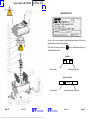
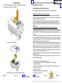
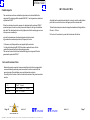
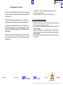
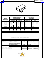
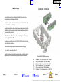
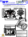
1
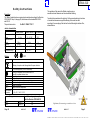
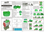
ΚΟΥΤΙ ΟΡΙΟ∆ΙΑΚΟΠΤΩΝ ΑΠΛΩΝ & ΑΝΤΙΕΚΚΡΗΚΤΙΚΩΝ
34706xA 1/22
ATTUATORI
PNEUMATIC ACTUATORS AND ACCESSORIES
ISO 9001:2000- Cert. n° 0210/4
OPERATION AND
SERVICE MANUAL
ΧΡΥΣΑΦΙ∆ΗΣ Α.Ε.
Notes:
II 2 D
CESI 03 ATEX 302 - 94/9/CE
G.T. ATTUATORI S.r.l.
Viale Europa, 17 20090 Cusago MI ITALY
Tel. +39 2 903.903.22 Fax +39 2 903.903.68
http://www.gtrevisan.it E-mail:[email protected]
Ex tD A21 IP66/67 T85 °C
SIGNAL BOX
“MINIBOX GT”
Edition 00 of 09/2008
.ΧΡΥΣΑΦΙ∆ΗΣ Α.Ε.: ΑΘΗΝΑ: ΑΓΡΙΝΙΟΥ 3 ΤΑΥΡΟΣ, ΤΗΛ.:210−4836315−20, ΦΑΞ:210−4817000. ΘΕΣ/ΚΗ: ∆Α12α−ΟΤ32 ΒΙ.ΠΕ.ΣΙΝ∆ΟΥ, ΤΗΛ.:2310−754681−3, ΦΑΞ:2310−751835
Adjustment
34706xA 2/22
To effect the regulation of the cams of the “Minibox” to proceed
to the opening of the box as it follows:
Safety instructions for the installation in
dangerous areas
Installation of the enclosure
Before installing the BOX,carefully read the user and maintenance manual.
1- To remove the srews of fixing of the cover of
the box with a screwdriver.
ΧΡΥΣΑΦΙ∆ΗΣ Α.Ε.
2-To lift the cover and uncouple the spherical index.
Page 8
MINIBOX GT
.ΧΡΥΣΑΦΙ∆ΗΣ Α.Ε.: ΑΘΗΝΑ: ΑΓΡΙΝΙΟΥ 3 ΤΑΥΡΟΣ, ΤΗΛ.:210−4836315−20, ΦΑΞ:210−4817000. ΘΕΣ/ΚΗ: ∆Α12α−ΟΤ32 ΒΙ.ΠΕ.ΣΙΝ∆ΟΥ, ΤΗΛ.:2310−754681−3, ΦΑΞ:2310−751835
Suitability of the Minibox for the installation site
In the case it is used in areas with danger of explosion,it is important to check that
the box is suitable for the area classification and for the characteristis of the inflammable
substances present on the installation.
The fundamental safety requirements against the risk of explosino in the classified
areas are established by the European directives 94/9/CE of 23 march 1994 (with
reference to the equipment) and 1999/92/CE of 16 December 1999 ( with reference to the
installations).
Areas with presence of gases,inflammable vapours or fogs,and dusts
The criteria for the classification of the areas with a risk of explosion are established by
the standard EN 60079-10(clasification of the dangerous areas due to the presence of
gases) and EN61241-10 (classification of the areas in which combustible duts can be
present).
The technical requirements of the electrical installations in the classified areas are given
by the regulation EN 60079-14 (Electrical constructions for explosive atmospheres due
to the presence of gases - Part 14: Electrical installations in areas with danger of explosions
due to the presence of gases (different from mines);
EN 60079 - 17 Electrical constructions for explosive atmospheres due the presence of
gases - Part 17: Check and maintenance of the electrical installation in areas with
danger of explosion du to the presence of gases (different from mines);EN 61241 - 14
Electrical constructions destined to be used in the presence of combustible dusts - Part
14: Choice and installation; and EN 61241 - 17 Electrical constructions destined to be
used in the presence of combustible dusts - Part 17 :
Check and maintenance of the electrical installations in areas with danger of explosion
(differnt from mines).
According to these technical and legislative provisions, the choice of the box must
consider the following factors:
- Type of installation: surface installations (group II)
- Area classification:0,1,2,20,21,22(for which equipment of 1,2,3 category
respetively is suitable)
- Characteristics of the inflammable sustances present in the form of gases,vapours
or fogs , and dusts layer.
- Sub-group IIA, IIB, IIC
- T6 temperature class (it defines the ignition temperature of gases)
- IP 66 (degree of protection)
MINIBOX GT
Page 17
34706xA 3/22
Safety instructions
Description
The “Minibox” model has been conceived and constructed according to the Directive
ATEX 94/9/CE Group II, category 2D,with reference to the standard EN 61241-0
and 61241-1
The protection mode is:
Ex tD A21 IP66/67 T 85° C
The regulation of the cams in the Minibox is gotten using a
screwdriver of small dimension as it lever described following.
To position the screwdriver in the lodging Á. of the cam and pushing in clockwise
or counterclockwise sense we get the widening of the center cam and
accordingly the uncoupling of the teeth on the shaft allowing the rotation of the,
aforesaid cams.
electric characteristics
Proximity sensors
Maximum nominal
voltage
Maximum nominal
current
Frequenzy
Environmental temp.
Inductive sensors
10 ÷ 60 v
25 ÷ 30 V DC
200 mA
3000 Hz
- 20 + 70 ° C
100 mA
- 20 + 70 ° C
Environmental temp.
....
....
II 2 D
Marking of compliance with the applicable European directives
Marking of compliance with the directive 94/9/CE
and with the relative technical rules.
Group II (surface)
Category 2 apparatus
Explosive atmosphere with presence of dusts
Protection through custody, method Á. zone 21
Degree of protection
Maximum surface temperature
-20 + 70° C -45°C + 70° C
Dangerous area
Page 16
5A
50 ÷ 60 Hz
- 20 + 70 ° C
n. of notified organism (for ATEX surveillance)
II
2
D
Ex tD A 21
IP66/67
T 85 °C
Environmental
temperature
Dusts
Dusts
250 V
- 45 + 70 ° C
Marking
....
Micro-mechanical
Zone 21
Zone 22
Installation category in compliance
with the Directive ATEX 94/9/CE
2D
3D
MINIBOX GT
Regulation of the cams using a screwdriver as lever
ΧΡΥΣΑΦΙ∆ΗΣ Α.Ε.
MINIBOX GT
Page 9
.ΧΡΥΣΑΦΙ∆ΗΣ Α.Ε.: ΑΘΗΝΑ: ΑΓΡΙΝΙΟΥ 3 ΤΑΥΡΟΣ, ΤΗΛ.:210−4836315−20, ΦΑΞ:210−4817000. ΘΕΣ/ΚΗ: ∆Α12α−ΟΤ32 ΒΙ.ΠΕ.ΣΙΝ∆ΟΥ, ΤΗΛ.:2310−754681−3, ΦΑΞ:2310−751835
34706xA 4/22
ΧΡΥΣΑΦΙ∆ΗΣ Α.Ε.
Finished the adjustment proceed with the riassembling of the box cover.
CAUTION: During disassembling and cams adjusting
it is possible that the O-Ring placed on the top of box
body comes out of proper seat.
Take care that the O-Ring is well placed into his seat before to
re-assemble the cover to avoid malfunction of the BEP-BOX
and/or leakages of the sealing.
Spare parts GT MM4 - GT MM2
Pos Description
Qty
Qty
MM4 MM2
1
Body
1
1
2
3
4
Cam shaft
Transparent indicator
Feet 20 -30
1
1
2
1
1
2
5
6
7
8
Board for microswitches
Cams
TCP screws M4x22
Cover
2
4
4
1
1
2
4
1
9
10
11
12
13
14
15
16
17
18
Benzing circlip Ø 7
Spherical Index suit of red line
Cover O-Ring Ø113.97x2.62
O-Ring Ø 50.52x1.78
TSP screws M5x8
TE screws M5x12
Flat washer Ø 5
O-Ring Ø 1.78x6.75
Label
Spacing ring
1
1
1
1
4
2
2
2
1
0
1
1
1
1
4
2
1
2
1
2
Material
Cod
Dye cast aluminium power coated
EN AB 46100
Steel nickeled
Polycarbonate
Dye cast aluminium power coated
EN AB 46100
Delrin
Stainless steel AISI 304
Dye cast aluminium power coated
EN AB 46100
Stainless steel DIN6799
Nylon
NBR (MO41)
NBR (MO41)
Stainless steel UNI-7688 DIN965
Stainless steel DIN933
Stainless steel DIN 125
NBR (MO41)
16251
16212
02263
16261
03938
02267
01299
16257
01226
02264
01583
01530
00999
01106
01233
01505
GT MM2
Adjustment of lower cams
Page 10
MINIBOX GT
.ΧΡΥΣΑΦΙ∆ΗΣ Α.Ε.: ΑΘΗΝΑ: ΑΓΡΙΝΙΟΥ 3 ΤΑΥΡΟΣ, ΤΗΛ.:210−4836315−20, ΦΑΞ:210−4817000. ΘΕΣ/ΚΗ: ∆Α12α−ΟΤ32 ΒΙ.ΠΕ.ΣΙΝ∆ΟΥ, ΤΗΛ.:2310−754681−3, ΦΑΞ:2310−751835
MINIBOX GT
Page 15
34706xA 5/22
Spare parts GT MM4
Identification
On top of box cover is present an identification plate showing the box type
identification an the serial number of the box.
On the lower left corner, close to the
and related technical data.
logo is indicated the switches type
Modello:
2C
Cams number
-
2M
Microswitches number
Numero di Serie:
4
Production year
Page 14
MINIBOX GT
00004
Progressive production number
Page 11
MINIBOX GT
ΧΡΥΣΑΦΙ∆ΗΣ Α.Ε.
.ΧΡΥΣΑΦΙ∆ΗΣ Α.Ε.: ΑΘΗΝΑ: ΑΓΡΙΝΙΟΥ 3 ΤΑΥΡΟΣ, ΤΗΛ.:210−4836315−20, ΦΑΞ:210−4817000. ΘΕΣ/ΚΗ: ∆Α12α−ΟΤ32 ΒΙ.ΠΕ.ΣΙΝ∆ΟΥ, ΤΗΛ.:2310−754681−3, ΦΑΞ:2310−751835
Spare parts
34706xA 6/22
Spare parts GTS 12
ΧΡΥΣΑΦΙ∆ΗΣ Α.Ε.
MINIBOX GT
.ΧΡΥΣΑΦΙ∆ΗΣ Α.Ε.: ΑΘΗΝΑ: ΑΓΡΙΝΙΟΥ 3 ΤΑΥΡΟΣ, ΤΗΛ.:210−4836315−20, ΦΑΞ:210−4817000. ΘΕΣ/ΚΗ: ∆Α12α−ΟΤ32 ΒΙ.ΠΕ.ΣΙΝ∆ΟΥ, ΤΗΛ.:2310−754681−3, ΦΑΞ:2310−751835
Pos Description
1
Body
Qty
1
2
3
4
Cam shaft
Transparent indicator
Feet 20 -30
1
1
2
5
6
7
8
Board for miscroswitches
Cams
TCP screws M4x22
Cover
2
2
4
1
9
10
11
12
13
14
15
16
17
18
19
20
21
22
Benzing circlip Ø 7
Spherical Index suit of red line
Cover O-Ring Ø113.97x2.62
O-Ring Ø 50.52x1.78
TCTC screws M5x7
Flat washer Ø 5
TE screws M5x12
O-Ring Ø 1.78x6.75
Label
Square of fixing
Blade for sensors
sensor
M 12 nut for sensor
Spacing ring
1
1
1
1
6
2
2
2
1
1
2
2
4
2
Material
Dye cast aluminium power coated
EN AB 46100
Steel nickeled
Polycarbonate
Dye cast aluminium power coated
EN AB 46100
Delrin
Stainless steel AISI 304
Dye cast aluminium power coated
EN AB 46100
Stainless steel DIN6799
Nylon
NBR (MO41)
NBR (MO41)
Stainless steel UNI-7688 DIN965
Stainless steel DIN933
Stainless steel DIN 125
NBR (MO41)
Nylon
Stainless steel
Stainless steel
Delrin
MINIBOX GT
Cod
16251
16212
02263
16261
03938
02267
01299
16257
01226
02264
01583
01530
00999
01106
01233
01505
Spare parts
MINIBOX GT
Spare parts GTS 12
Pos Description
1
Body
Qty
1
2
3
4
Cam shaft
Transparent indicator
Feet 20 -30
1
1
2
5
6
7
8
Board for miscroswitches
Cams
TCP screws M4x22
Cover
2
2
4
1
9
10
11
12
13
14
15
16
17
18
19
20
21
22
Benzing circlip Ø 7
Spherical Index suit of red line
Cover O-Ring Ø113.97x2.62
O-Ring Ø 50.52x1.78
TCTC screws M5x7
Flat washer Ø 5
TE screws M5x12
O-Ring Ø 1.78x6.75
Label
Square of fixing
Blade for sensors
sensor
M 12 nut for sensor
Spacing ring
1
1
1
1
6
2
2
2
1
1
2
2
4
2
34706xA 7/22
Material
Dye cast aluminium power coated
EN AB 46100
Steel nickeled
Polycarbonate
Dye cast aluminium power coated
EN AB 46100
Delrin
Stainless steel AISI 304
Dye cast aluminium power coated
EN AB 46100
Stainless steel DIN6799
Nylon
NBR (MO41)
NBR (MO41)
Stainless steel UNI-7688 DIN965
Stainless steel DIN933
Stainless steel DIN 125
NBR (MO41)
Cod
16251
16212
02263
16261
03938
02267
01299
16257
01226
02264
01583
01530
00999
01106
01233
01505
Nylon
Stainless steel
Stainless steel
Delrin
MINIBOX GT
ΧΡΥΣΑΦΙ∆ΗΣ Α.Ε.
.ΧΡΥΣΑΦΙ∆ΗΣ Α.Ε.: ΑΘΗΝΑ: ΑΓΡΙΝΙΟΥ 3 ΤΑΥΡΟΣ, ΤΗΛ.:210−4836315−20, ΦΑΞ:210−4817000. ΘΕΣ/ΚΗ: ∆Α12α−ΟΤ32 ΒΙ.ΠΕ.ΣΙΝ∆ΟΥ, ΤΗΛ.:2310−754681−3, ΦΑΞ:2310−751835
Spare parts GT MM4
34706xA 8/22
Identification
ΧΡΥΣΑΦΙ∆ΗΣ Α.Ε.
On top of box cover is present an identification plate showing the box type
identification an the serial number of the box.
On the lower left corner, close to the
and related technical data.
logo is indicated the switches type
Modello:
2C
Cams number
-
2M
Microswitches number
Numero di Serie:
4
Production year
Page 14
MINIBOX GT
.ΧΡΥΣΑΦΙ∆ΗΣ Α.Ε.: ΑΘΗΝΑ: ΑΓΡΙΝΙΟΥ 3 ΤΑΥΡΟΣ, ΤΗΛ.:210−4836315−20, ΦΑΞ:210−4817000. ΘΕΣ/ΚΗ: ∆Α12α−ΟΤ32 ΒΙ.ΠΕ.ΣΙΝ∆ΟΥ, ΤΗΛ.:2310−754681−3, ΦΑΞ:2310−751835
00004
Progressive production number
MINIBOX GT
Page 11
Spare parts GT MM4 - GT MM2
Pos Description
Finished the adjustment proceed with the riassembling of the box cover.
CAUTION: During disassembling and cams adjusting
it is possible that the O-Ring placed on the top of box
body comes out of proper seat.
Take care that the O-Ring is well placed into his seat before to
re-assemble the cover to avoid malfunction of the BEP-BOX
and/or leakages of the sealing.
Qty
Qty
MM4 MM2
1
Body
1
1
2
3
4
Cam shaft
Transparent indicator
Feet 20 -30
1
1
2
1
1
2
5
6
7
8
Board for microswitches
Cams
TCP screws M4x22
Cover
2
4
4
1
1
2
4
1
9
10
11
12
13
14
15
16
17
18
Benzing circlip Ø 7
Spherical Index suit of red line
Cover O-Ring Ø113.97x2.62
O-Ring Ø 50.52x1.78
TSP screws M5x8
TE screws M5x12
Flat washer Ø 5
O-Ring Ø 1.78x6.75
Label
Spacing ring
1
1
1
1
4
2
2
2
1
0
1
1
1
1
4
2
1
2
1
2
34706xA 9/22
Material
Cod
Dye cast aluminium power coated
EN AB 46100
Steel nickeled
Polycarbonate
Dye cast aluminium power coated
EN AB 46100
Delrin
Stainless steel AISI 304
Dye cast aluminium power coated
EN AB 46100
Stainless steel DIN6799
Nylon
NBR (MO41)
NBR (MO41)
Stainless steel UNI-7688 DIN965
Stainless steel DIN933
Stainless steel DIN 125
NBR (MO41)
16251
16212
02263
16261
03938
02267
01299
16257
01226
02264
01583
01530
00999
01106
01233
01505
GT MM2
Adjustment of lower cams
Page 10
MINIBOX GT
Page 15
MINIBOX GT
ΧΡΥΣΑΦΙ∆ΗΣ Α.Ε.
.ΧΡΥΣΑΦΙ∆ΗΣ Α.Ε.: ΑΘΗΝΑ: ΑΓΡΙΝΙΟΥ 3 ΤΑΥΡΟΣ, ΤΗΛ.:210−4836315−20, ΦΑΞ:210−4817000. ΘΕΣ/ΚΗ: ∆Α12α−ΟΤ32 ΒΙ.ΠΕ.ΣΙΝ∆ΟΥ, ΤΗΛ.:2310−754681−3, ΦΑΞ:2310−751835
34706xA 10/22
ΧΡΥΣΑΦΙ∆ΗΣ Α.Ε.
Safety instructions
Description
The “Minibox” model has been conceived and constructed according to the Directive
ATEX 94/9/CE Group II, category 2D,with reference to the standard EN 61241-0
and 61241-1
The protection mode is:
Ex tD A21 IP66/67 T 85° C
The regulation of the cams in the Minibox is gotten using a
screwdriver of small dimension as it lever described following.
To position the screwdriver in the lodging Á. of the cam and pushing in clockwise
or counterclockwise sense we get the widening of the center cam and
accordingly the uncoupling of the teeth on the shaft allowing the rotation of the,
aforesaid cams.
electric characteristics
Proximity sensors
Maximum nominal
voltage
Maximum nominal
current
Frequenzy
Environmental temp.
Inductive sensors
10 ÷ 60 v
25 ÷ 30 V DC
200 mA
3000 Hz
- 20 + 70 ° C
100 mA
- 20 + 70 ° C
Environmental temp.
....
....
II 2 D
Marking of compliance with the applicable European directives
Marking of compliance with the directive 94/9/CE
and with the relative technical rules.
Group II (surface)
Category 2 apparatus
Explosive atmosphere with presence of dusts
Protection through custody, method Á. zone 21
Degree of protection
Maximum surface temperature
-20 + 70° C -45°C + 70° C
Dangerous area
Page 16
5A
50 ÷ 60 Hz
- 20 + 70 ° C
n. of notified organism (for ATEX surveillance)
II
2
D
Ex tD A 21
IP66/67
T 85 °C
Environmental
temperature
Dusts
Dusts
250 V
- 45 + 70 ° C
Marking
....
Micro-mechanical
Zone 21
Zone 22
Installation category in compliance
with the Directive ATEX 94/9/CE
2D
3D
MINIBOX GT
.ΧΡΥΣΑΦΙ∆ΗΣ Α.Ε.: ΑΘΗΝΑ: ΑΓΡΙΝΙΟΥ 3 ΤΑΥΡΟΣ, ΤΗΛ.:210−4836315−20, ΦΑΞ:210−4817000. ΘΕΣ/ΚΗ: ∆Α12α−ΟΤ32 ΒΙ.ΠΕ.ΣΙΝ∆ΟΥ, ΤΗΛ.:2310−754681−3, ΦΑΞ:2310−751835
Regulation of the cams using a screwdriver as lever
MINIBOX GT
Page 9
Adjustment
To effect the regulation of the cams of the “Minibox” to proceed
to the opening of the box as it follows:
34706xA
Safety instructions for the installation
in
dangerous areas
11/22
Installation of the enclosure
Before installing the BOX,carefully read the user and maintenance manual.
1- To remove the srews of fixing of the cover of
the box with a screwdriver.
2-To lift the cover and uncouple the spherical index.
Page 8
MINIBOX GT
Suitability of the Minibox for the installation site
In the case it is used in areas with danger of explosion,it is important to check that
the box is suitable for the area classification and for the characteristis of the inflammable
substances present on the installation.
The fundamental safety requirements against the risk of explosino in the classified
areas are established by the European directives 94/9/CE of 23 march 1994 (with
reference to the equipment) and 1999/92/CE of 16 December 1999 ( with reference to the
installations).
Areas with presence of gases,inflammable vapours or fogs,and dusts
The criteria for the classification of the areas with a risk of explosion are established by
the standard EN 60079-10(clasification of the dangerous areas due to the presence of
gases) and EN61241-10 (classification of the areas in which combustible duts can be
present).
The technical requirements of the electrical installations in the classified areas are given
by the regulation EN 60079-14 (Electrical constructions for explosive atmospheres due
to the presence of gases - Part 14: Electrical installations in areas with danger of explosions
due to the presence of gases (different from mines);
EN 60079 - 17 Electrical constructions for explosive atmospheres due the presence of
gases - Part 17: Check and maintenance of the electrical installation in areas with
danger of explosion du to the presence of gases (different from mines);EN 61241 - 14
Electrical constructions destined to be used in the presence of combustible dusts - Part
14: Choice and installation; and EN 61241 - 17 Electrical constructions destined to be
used in the presence of combustible dusts - Part 17 :
Check and maintenance of the electrical installations in areas with danger of explosion
(differnt from mines).
According to these technical and legislative provisions, the choice of the box must
consider the following factors:
- Type of installation: surface installations (group II)
- Area classification:0,1,2,20,21,22(for which equipment of 1,2,3 category
respetively is suitable)
- Characteristics of the inflammable sustances present in the form of gases,vapours
or fogs , and dusts layer.
- Sub-group IIA, IIB, IIC
- T6 temperature class (it defines the ignition temperature of gases)
- IP 66 (degree of protection)
Page 17
MINIBOX GT
ΧΡΥΣΑΦΙ∆ΗΣ Α.Ε.
.ΧΡΥΣΑΦΙ∆ΗΣ Α.Ε.: ΑΘΗΝΑ: ΑΓΡΙΝΙΟΥ 3 ΤΑΥΡΟΣ, ΤΗΛ.:210−4836315−20, ΦΑΞ:210−4817000. ΘΕΣ/ΚΗ: ∆Α12α−ΟΤ32 ΒΙ.ΠΕ.ΣΙΝ∆ΟΥ, ΤΗΛ.:2310−754681−3, ΦΑΞ:2310−751835
34706xA 12/22
INSTALLATION
Cable inputs
The connections must have realized through entrances of cable certified for the
categories 2D complying with the standard EN61241-1 and to guarantee a level least
of protection IP66/67.
When the cable input is made by means of a cable gland with a minimum IP66/67
protection degree,it must be correctly chosen with respect to the type of installation
and cable.The cable glandmust be strictly tightened so that the sealing rigs can create the pressure necessary to:
Adjust the feet-brackets at desired height, in order to insert the milled bottom
part of the box rod into the slot on the upper part of the actuator shaft.
The feet-brackets may be inverted to change the wheelbase of fixing bolts from
80 mm. to 130 mm.
Fix the box to the actuator by mean the bolts issued with the box.
a) avoid the transmission of mechanical strains onto the terminals:
b) guarantee the mechanical protection (IP degree) of the box.
Furthemore ,any fittings which are not supplied by the costructor.
For the cylindrical edging AN ISO 228 must have realized a device of block
against the loosening using a loctite sealing procedure.
The used not holes must be closed with certified plugs for categories 2D and to
guarantee the protection IP66/67
Ground connection
Besides the ground connection foreseen inside the box,the latter is equipped with
a second externally positioned ground connection.It must be connected to the
general ground of the installation using a suitable section conductor.
According to the S section of the line conductor,the section of the ground conductor
must be:
=S
16
≥ 0.5 S
Per S ≤ 16mm²
Per 16 mm ²< S ≤ 35 mm ²
Per S > 35 mm ²
Page 18
MINIBOX GT
ΧΡΥΣΑΦΙ∆ΗΣ Α.Ε.
.ΧΡΥΣΑΦΙ∆ΗΣ Α.Ε.: ΑΘΗΝΑ: ΑΓΡΙΝΙΟΥ 3 ΤΑΥΡΟΣ, ΤΗΛ.:210−4836315−20, ΦΑΞ:210−4817000. ΘΕΣ/ΚΗ: ∆Α12α−ΟΤ32 ΒΙ.ΠΕ.ΣΙΝ∆ΟΥ, ΤΗΛ.:2310−754681−3, ΦΑΞ:2310−751835
MINIBOX GT
Page 7
34706xA 13/22
Putting out of service
Whenever it is requested to put out of service the box, it is necessary
to follow some basic rules able to protect the operator health and the
environment too.
Sheaths, flexible tubes and plastic materials, or in any case non
metallic parts, must be disassembled and disposed separately.
Pneumatic and electrical components as valves, solenoid valves,
switches and transformers, if any, sould be disassembled to be reused if in good conditions otherwise to be overhauled and recycled
when possible.
Metal parts sould be disassembled and grouped together by metal
type to be casted again in order to allow the recycling of the materials
forming the box.
Page 6
MINIBOX GT
The “Minibox GT” needs no extraordinary maintenance.In fact,inside it,
there are no organs wich need it.
When it is necessary to open the box,unscrew the 4 fixing srews.
ONLY AFTER CUTTING THE VOLTAGE.
- The terminals of the electrical connections must be strictly tightened to avoid high
contact resistance and consequent overheating
- The cover must be stictly tightened and blocked against the loosening of the
suitable locking srew.
- The replacement of fittings and parts of the cable inputs must be carried out using
identical components to those supplied by the manufacturer in order to garantee
a suitable protection.
- When substituting the clamping screws please make sure you use screw type
A2-70 UNI 5931
Page 19
MINIBOX GT
ΧΡΥΣΑΦΙ∆ΗΣ Α.Ε.
.ΧΡΥΣΑΦΙ∆ΗΣ Α.Ε.: ΑΘΗΝΑ: ΑΓΡΙΝΙΟΥ 3 ΤΑΥΡΟΣ, ΤΗΛ.:210−4836315−20, ΦΑΞ:210−4817000. ΘΕΣ/ΚΗ: ∆Α12α−ΟΤ32 ΒΙ.ΠΕ.ΣΙΝ∆ΟΥ, ΤΗΛ.:2310−754681−3, ΦΑΞ:2310−751835
34706xA 14/22
ΧΡΥΣΑΦΙ∆ΗΣ Α.Ε.
Electrical connections
Caution: To be sure that power is swiched off before
to proceed with electrical connections.
MINIBOX GTMM2
Safety an caution
general conditions
The same construction of the box is practically the protections agaist
all the parts in motion all placed inside the box.
Possible damaged power cable must be replaced !
For all the works regarding installation, starting up, equipping, use,
utilization and using mode modifications, ordinary maintenance and
inspections must be followed the putting out of service procedures
specified in this Operator’s manual.
The Operator’s manual must be always to hand, in order to have the
possibility to look it up to verify correct operating cicle every time
there are doubts or it is necessary a new setting up.
Board MINIBOX MM2 connection
5.
6.
7.
8.
9.
10.
P
Page 20
Commone “sup” micro-switch max. ~250V 5A
N.O. (normally open) “sup” micro-switch
N.C. (normally closed) “sup” micro-switch
N.C. (normally closed) “inf” micro-switch
N.O. (normally open) “inf” micro-switch
Commone “inf” micro-switch max. ~250V 5A
2 MINIBOX GT
.ΧΡΥΣΑΦΙ∆ΗΣ Α.Ε.: ΑΘΗΝΑ: ΑΓΡΙΝΙΟΥ 3 ΤΑΥΡΟΣ, ΤΗΛ.:210−4836315−20, ΦΑΞ:210−4817000. ΘΕΣ/ΚΗ: ∆Α12α−ΟΤ32 ΒΙ.ΠΕ.ΣΙΝ∆ΟΥ, ΤΗΛ.:2310−754681−3, ΦΑΞ:2310−751835
MINIBOX GT
Page 5
34706xA 15/22
ATEX 94/9/CE
ISO 9001:2000 - Cert. n° 0210/3
BOX INDICATORE / SIGNAL BOX
" MINIBOX GT " MODELLO / MODEL: " GT MM2 "
MICRO MECCANICI / MICRO-SWITCH: " OMROM SSG-5L2P "
36
22.5
30
20
2 FORI M20x1.5
2 HOLES M20x1.5
10
30
80
FISSAGGIO INTERNO-INSIDE FIXING
130
FISSAGGIO ESTERNO-EXTERNAL FIXING
PIEDI MOBILI CORTI
SHORT MOVING FEET
PIEDI MOBILI LUNGHI
LONG MOVING FEET
136
128
88
INDICATORE DI POSIZIONE
POSITION INDICATOR
14
2 1
4 3
5
6
8 7
09
1
11
13 12
CONNESSIONE SCHEDA MINIBOX GT MM2
1 - Comune microinterrutore "A" max. ~250V 5A
2 - N.O. (normalmente aperto) microinterrutore "A"
3 - N.C. (normalmente chiuso) microinterrutore "A"
4 - Comune microinterrutore "B"
5 - N.O. (normalmente aperto) microinterrutore "B"
6 - N.C. (normalmente chiuso) microinterrutore "B"
Board MINIBOX GT MM2 connection
1 - Commone "sup" micro-switch max. ~250V 5A
2 - N.O. (normally open) "sup" micro-switch
3 - N.C. (normally closed) "sup" micro-switch
4 - N.C. (normally closed) "inf" micro-switch
5 - N.O. (normally open) "inf" micro-switch
6 - Commone "inf" micro-switch max. ~250V 5A
Μ.Γ.ΧΡΥΣΑΦΙ∆ΗΣ Α.Ε.
136 (MONTAGGIO PIEDINI LUNGHI)
ASSEMBLAGE LONG FEET
126
53.5
29.5
105.5 (NAMUR H=20)
CUPOLA TRASPARENTE
TRANSPARENT DOME
10
115.5 (MONTAGGIO PIEDINI CORTI) NAMUR H=30
ASSEMBLAGE SHORT FEET
MASSA A TERRA ESTERNA
EXTERNAL GROUND
34706xA 16/22
CARATTERISTICHE GENERALI / GENERAL RATINGS
Tensioni
Rated voltage
125 VAC
250 VAC
8 VDC
14 VDC
30 VDC
125 VDC
250 VDC
Senza carico induttivo
Non inductive load
Carico lampada
Carico resistivo
Lamp load
Resistive load
NC
NO
NC
NO
5(0,1) A (see note 1)
1,5A
0,7A
3A
1A
0,5A
5A
2A
5A
2A
4(0,1) A (see note 1)
2A
0,4A
0,05A
0,2A
0,03A
Carico induttivo
Inductive load
Carico induttivo
Carico motore Motor
Inductive load
load
NC
NO
NC
NO
3A
2,5A
1,3A
2A
1,5A
0,8A
5A
3A
4A
3A
3A
3A
0,4A
0,05A
0,2A
0,05A
NOTE: 1 - The values in the parentheses are for the SSG-01
SPECIFICHE CONTATTI / CONTACT SPECIFICATIONS
ARTICOLO / ITEM
CONTATTI
CONTACT
INRUSH CURRENT
SSG-5
SSG-01H.T
SSG-01P
SPECIFICHE / SPECIFICATION
RIVET
CROSSBAR
CROSSBAR
MATERIALE / MATERIAL
APERTURA (VALORE STANDARD)
GAP (STANDARD VALUE)
NC
SILVER
GOLD ALLOY
GOLD ALLOY
0.5 mm
0.25 mm
20 A MAX
10 A MAX
1 A MAX
1 A MAX
1 A MAX
1 A MAX
160 mA at 5 VDC
1 mA at 5 VDC
1 mA at 5 VDC
NO
MINIMO CARICO APPLICABILE
MINIMUM APPLICABLE LOAD
Μ.Γ.ΧΡΥΣΑΦΙ∆ΗΣ Α.Ε.
0.5 mm
34706xA 17/22
Warnings
MINIBOX GTMM4
The installation and the starting up of the BOX have to be done
as described on following instructions.
The device can be put in service only by personnel which know the
contents of these instructions.
Pnematic actuators pruduce a strong torque consequently during the
installation and the staring up must be observed safety instructions
to avoid possible injuries.
Before to open the box cover be sure that power has been
previously switched off.
Strongly screw in the screws UNI 5931 IN AISI 304 which close the
cover before the staring up.
Take care that may be present residual electrostatic charge.
For cleaning use damp cloth only.
Besides the ground connection foressen inside yhe box,the later is
equipped with a second externally positioned ground connection.
Board MINIBOX GTMM4 connection
5.
6.
7.
8.
9.
10.
Page 4
MINIBOX GT
Commone “sup” micro-switch max. ~250V 5A
N.O. (normally open) “sup” micro-switch
N.C. (normally closed) “sup” micro-switch
N.C. (normally closed) “inf” micro-switch
N.O. (normally open) “inf” micro-switch
Commone “inf” micro-switch max. ~250V 5A
Page 21
MINIBOX GT
ΧΡΥΣΑΦΙ∆ΗΣ Α.Ε.
.ΧΡΥΣΑΦΙ∆ΗΣ Α.Ε.: ΑΘΗΝΑ: ΑΓΡΙΝΙΟΥ 3 ΤΑΥΡΟΣ, ΤΗΛ.:210−4836315−20, ΦΑΞ:210−4817000. ΘΕΣ/ΚΗ: ∆Α12α−ΟΤ32 ΒΙ.ΠΕ.ΣΙΝ∆ΟΥ, ΤΗΛ.:2310−754681−3, ΦΑΞ:2310−751835
34706xA 18/22
Generality
ΧΡΥΣΑΦΙ∆ΗΣ Α.Ε.
MINIBOX GTS 3.5
Board MINIBOX GTS 3.5 connection
The Box “Minibox” model conceived and constructed according to the
Directive ATEX94/9/CE with reference to the European Regulation EN
61241-0 (General requirements)Electrical apparatus for use in the presence
of combustible dust and EN 61241-1 (Protection by enclosures “tD”)
Electrical apparatus for use in
the presence of combustible dust is installed on a rotating pneumatic
actuator,mounted on a ball valve,butterfly valve,male valve,roller shutter
valve or on a mechanical organwhich requires a position indication and,as
a consequence,an electrical signal.
Made by die-cast aluminium and painted with epoxy-polyester powder, the
signal Boxes of G.T. ATTUATORI have the possibility to be adjusted in
height towards the upper surface of the actuator.
Usable without
distinction with shafs having protrusion over the actuator top of
20mm.(NAMUR 20), 30mm.(NAMUR 30), 40mm.and 50mm.(NAMUR 50),
due to the possibility of easy adjustment by fixed steps, obtainable simply
changing the position of the screws which fasten the feet-brackets on the
box body.
Other peculiarity is the possibility to easily self-adapt to the two different
top drillings required by NAMUR standard for the fixing of the box to the
actuator body that are mm.30x80 or mm. 30x130, with the simple
reversal of the two feet-brackets from left to right and vice versa.
The regulation of the switches control cams happens in simple way with
the aid of a screwdriver as explained to page 9.
The terminal boards are pull-out type to make easier the cables connection.
The signal box is endowed with a spherical tridimensional indicator.
Rod and all the fasteners are in stainell steel ,the cams comand in nickeled
steel.
Page 22
MINIBOX GT
.ΧΡΥΣΑΦΙ∆ΗΣ Α.Ε.: ΑΘΗΝΑ: ΑΓΡΙΝΙΟΥ 3 ΤΑΥΡΟΣ, ΤΗΛ.:210−4836315−20, ΦΑΞ:210−4817000. ΘΕΣ/ΚΗ: ∆Α12α−ΟΤ32 ΒΙ.ΠΕ.ΣΙΝ∆ΟΥ, ΤΗΛ.:2310−754681−3, ΦΑΞ:2310−751835
MINIBOX GT
Page 3
34706xA 19/22
Introduction
MINIBOX GTS12
Kind Customer.
The G.T. Attuatori thanks you to have chosen this new accessory
“Minibox GT” that it has been planned for being used in areas with
danger of explosion.
The Minibox GT is distinguished for his compact structure, simple of
use with a very modern design, guaranteeing tall output and precision,
being built with the employment of components and selected
materials having high reliability and duration.
Board MINIBOX GTS 12 connection
5.
6.
7.
8.
9.
10.
Page 2
MINIBOX GT
Negative ground “inf” sensor
PNP positive output for user “inf” sensor
Supply of “inf” sensor 10÷30 VDC max. 100mA
Supply of “sup” sensor 10÷30 VDC max. 100mA
Positve ground “sup” sensor
Negative ground “sup” sensor
Page 23
MINIBOX GT
ΧΡΥΣΑΦΙ∆ΗΣ Α.Ε.
.ΧΡΥΣΑΦΙ∆ΗΣ Α.Ε.: ΑΘΗΝΑ: ΑΓΡΙΝΙΟΥ 3 ΤΑΥΡΟΣ, ΤΗΛ.:210−4836315−20, ΦΑΞ:210−4817000. ΘΕΣ/ΚΗ: ∆Α12α−ΟΤ32 ΒΙ.ΠΕ.ΣΙΝ∆ΟΥ, ΤΗΛ.:2310−754681−3, ΦΑΞ:2310−751835
34706xA 20/22
Tehnical data
ΧΡΥΣΑΦΙ∆ΗΣ Α.Ε.
Allowable environment
Temperature
Protection type
Dimensions
-20 + 70° C on work
-40 + 80° C stock
IP66/67
See on lay-out
Approximate weight
Body and brackets
0 ,6 Kg
Dye cast aluminium power coated
(lega EN AC -AISI 11 Cu2 (Fe) 2Fe
UNI EN 1706
Extractable 1,5mm² terminals
AW G14
Stainless steel AISI 304 Class A2-70
UNI 5931
They must be certified according to the
standard EN60079-0 , EN 60079-1
EN 61241-0 ed EN 61241-1 in compliance
with the Directive ATEX 94/9/CE
and guaranteeing an IP66 minimum
protection degree.
Reversibile
adjustable with cams
OMRON SSG-5L2P~250V 5 A or
Similar
P+F NBN4-12GM40-E2 ÷ 30V
d.c. 100mA or similar
P+F SC3,5 - N0 BLAU
II 1 D Ex ia D20 T 108°C
II 3 G Ex nL IIC T6 X
II 3 D IP 67 T 112°c X
100mA or similar
Electrical connections
Fasteners
Connection cables fittings
Rotation way
Adjustment
Mechanical microswitches
max.4
Proximity sensors
max.2
Inductive sensors
max.2
Page 24
MINIBOX GT
.ΧΡΥΣΑΦΙ∆ΗΣ Α.Ε.: ΑΘΗΝΑ: ΑΓΡΙΝΙΟΥ 3 ΤΑΥΡΟΣ, ΤΗΛ.:210−4836315−20, ΦΑΞ:210−4817000. ΘΕΣ/ΚΗ: ∆Α12α−ΟΤ32 ΒΙ.ΠΕ.ΣΙΝ∆ΟΥ, ΤΗΛ.:2310−754681−3, ΦΑΞ:2310−751835
Summary
Introduction.......................................................... 2
Generality............................................................. 3
Warnings.............................................................. 4
Safety and caution general conditions..................... 5
Putting out of service............................................. 6
Installation.............................................................7
Adjustment........................................................... 8
Identification.........................................................11
Spare parts GTS 12............................................13
Spare parts GTMM4 - GTMM2............................14
Safety instructions.................................................. 16
Description......................................................... 16
Electric features................................................. 16
Marking.............................................................. 16
Safety istructions for the installation
in dangerous areas.....................................................17
Suitability of the Minibox GT for the installation....... 17
Site areas with presence of dusts........................ 17
Cable inputs........................................................ 18
Ground connection.............................................. 18
Checks and maintenance of the enclosure “tD”..... 19
Electrical connections............................................. 20
Minibox GTMM2................................................. 20
Minibox GTMM4................................................. 21
Minibox GTS 3,5................................................. 22
Minibox GTS12................................................... 23
Technical data........ ............................................ 24
Lay - out.............................................................. 25
MINIBOX GT
Page 1
34706xA 21/22
ATEX 94/9/CE
ISO 9001:2000 - Cert. n° 0210/3
BOX INDICATORE / SIGNAL BOX
" MINIBOX GT " MODELLO / MODEL: " GTS 12 "
SENSORE / SENSOR: " P+F NBN4-12 GM40-E2 "
36
22.5
ASSEMBLAGE LONG FEET
2 FORI M20x1.5
2 HOLES M20x1.5
136 (MONTAGGIO PIEDINI LUNGHI)
30
20
126
53.5
29.5
105.5 (NAMUR H=20)
CUPOLA TRASPARENTE
TRANSPARENT DOME
10
115.5 (MONTAGGIO PIEDINI CORTI) NAMUR H=30
ASSEMBLAGE SHORT FEET
MASSA A TERRA ESTERNA
EXTERNAL GROUND
30
10
80
FISSAGGIO INTERNO-INSIDE FIXING
PIEDI MOBILI CORTI
SHORT MOVING FEET
130
FISSAGGIO ESTERNO-EXTERNAL FIXING
9
8
7
6
5
4
3
2
1
PIEDI MOBILI LUNGHI
LONG MOVING FEET
13
12
11
10
136
14
128
88
INDICATORE DI POSIZIONE
POSITION INDICATOR
Μ.Γ.ΧΡΥΣΑΦΙ∆ΗΣ Α.Ε.
5 6 7 8 9 10 -
Connessione scheda MINIBOX GTS 12
Massa-negativa sensore " inf "
Uscita positiva PNP per utilizzatore sensore " inf "
Alimentazione sensore 10÷30 VDC max. 100mA sensore " inf "
Alimentazione sensore 10÷30 VDC max. 100mA sensore "sup"
Uscita positiva PNP per utilizzatore sensore " sup "
Massa-negativa sensore "sup"
Board MINIBOX GTS 12 connection
5 - Negative ground "inf" sensor
6 - PNP positive output for user "inf" sensor
7 - Supply of "inf" sensor 10 ÷30 VDC max.100A
8 - Supply of "sup" sensor 10 ÷30 VDC max. 100mA
9 - Positive ground "sup" sensor
10 - Negative ground "sup" sensor