1
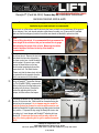
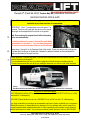
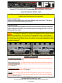
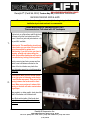
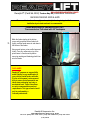
ReadyLift® (Part# 66-3050) Torsion Key Kit, Installation Instructions
GM 2500/3500/HD 2WD & 4WD
Please read instructions thoroughly and completely before beginning installation.
Installation by a trained mechanic is recommended.
SAFETY WARNING:ReadyLift Suspension Inc. recommends this system be installed by a professional technician. In addition to these instructions, professional knowledge of disassembly/ reassembly procedures and
post installation checks must be known.
PRODUCT SAFETY WARNING:Modifying your vehicle ride height may result in the vehicle handling differently than a factory equipped vehicle. Extreme care must be used to prevent loss of control or vehicle rollover.
Failure to drive your modified vehicle safely may result in serious injury or death. ReadyLift Suspension Inc.
does not recommend the combined use of suspension lifts, body lifts, or other lifting devices. You should
never operate your modified vehicle under the influence of alcohol or drugs. Always drive your modified vehicle
at reduced speeds to ensure your ability to control your vehicle under all driving conditions. Always wear your
seat belt.
Pre-Installation Notes
1. Special literature required: OE Service Manual for model/year of vehicle. Refer to manual for proper disassembly/reassembly procedures of OE and related components.
2. Adhere to recommendations when replacement fasteners, retainers and keepers are called out in the OE
manual.
3. Larger rim and tire combinations may increase leverage on suspension, steering, and related components.
When selecting combinations larger than OE, consider the additional stress you could be inducing on the OE
and related components.
4. Post suspension system vehicles may experience drive line vibrations. Angles may require tuning, slider on
shaft may require replacement, shafts may need to be lengthened or trued, and U-joints may need to be replaced.
5. Secure and properly block vehicle prior to installation of ReadyLift Suspension Inc. components. Always
wear safety glasses when using power tools.
6. If installation is to be performed without a hoist, ReadyLift aSuspension Inc. recommends rear alterations
first.
7. Due to payload options and initial ride height variances, the amount of lift is a base figure. Final ride height
dimensions may vary in accordance to original vehicle attitude. Always measure the attitude prior to beginning
installation.
POST-INSTALLATION WARNINGS
1. Check all fasteners for proper torque. Check to ensure for adequate clearance between all rotating, mobile,
fixed, and heated members. Verify clearance between exhaust and brake lines, fuel lines, fuel tank, floor
boards and wiring harness. Check steering gear for clearance. Test and inspect brake system.
2. Perform steering sweep to ensure front brake hoses have adequate slack and do not contact any rotating,
mobile or heated members. Inspect rear brake hoses at full extension for adequate slack. Failure to perform
hose check/ replacement may result in component failure. Longer replacement hoses, if needed can be purchased from a local parts supplier.
3. Headlight adjustment is highly recommended.
4. Re-torque all fasteners after 500 miles. Always inspect fasteners and components during routine servicing.
ReadyLift Suspension Inc.
3201 W MacArthur Blvd, Santa Ana, CA, 92704
Toll Free (888) 922 -2294 Local (714) 862-2968 Fax (714) 862-2972
7/27/2010
ReadyLift® (Part# 66-3050) Torsion Key Kit, Installation Instructions
GM 2500/3500/HD 2WD & 4WD
Please read instructions thoroughly and completely before beginning installation.
Installation by a trained mechanic is recommended.
Position truck on a flat surface and lift vehicle by the frame so that the front wheels are off the ground.
Use a minimum 3 ton jack stands and place under frame for safety or a (2) two post lift if available.
Make sure that the emergency brake is on and the rear wheels are blocked to prevent a rollout.
1.
2.
3.
4.
Note:
Prior to lifting the vehicle, it is recommended that you measure the
stock height of the vehicle so that you have a base line to gauge
after adjusting the height of the vehicle. Measuring the vehicle
from the bottom of the wheel to the lip of the fender is
recommended.
Remove front driver’s side wheel. Remove front shock. Remove the two bolts
that attach the lower shock bracket to
the lower control arm. Install ReadyLift®
shock bracket. Be sure to use a small
amount of thread locker on the two
shock bracket mounting bolts and the
lower shock bolt. Re-install shocks.
Please note that the lower shock bolt will
be inserted from the opposite direction
that it was removed on 4x4 models.
Using a ReadyLift® Torsion Bar Unloading Tool (Part#66-7822A), compress the
driver’s side key so that the keeper and
adjusting bolt are loose. Remove the
torsion key adjusting bolt from the
keeper, and then remove the keeper.
After
Brake Caliper
Keeper
ReadyLift® Torsion bar
unloading tool.
Adjusting Bolt
Releasing the tension on the unloading tool will now release the
Factory Bolt
tension on the torsion bar. Slide torsion bar forward allowing the
torsion key to be removed. An air hammer may be needed to
push the torsion bar forward on vehicles with excessive rust.
Install the ReadyLift® Forged torsion key and slide torsion bar back
into position. Compress the key using the ReadyLift® torsion bar
unloading tool. Insert keeper and ReadyLift® adjusting bolt supplied in kit. Please note that some vehicles may require the
use of the factory adjusting bolt to get the maximum amount
of lift.
ReadyLift Suspension Inc.
ReadyLift® Bolt
3201 W MacArthur Blvd, Santa Ana, CA, 92704
Toll Free (888) 922 -2294 Local (714) 862-2968 Fax (714) 862-2972
7/27/2010
ReadyLift® (Part# 66-3050) Torsion Key Kit, Installation Instructions
GM 2500/3500/HD 2WD & 4WD
Please read instructions thoroughly and completely before beginning installation.
Installation by a trained mechanic is recommended.
IMPORTANT! – Each ¼” of adjustment on the bolt equals 1” at
the wheel. Check the ride height with the vehicle on the ground.
Ride height can be adjusted with the vehicle on the ground.
5.
Note: Over-cranking the suspension will affect ride quality
and is not recommended.
.75”
The distance between the upper A-Arm and the metal bump
stop should be no less than ¾”. Any less than this amount
will result in a harsh ride and put strain on the CV half shafts.
6.
Repeat steps 1 through 5 on the Passenger Side of the vehicle. Follow each step closely, making sure
to double-check the torque on all fasteners. Measure the distance between the tires and fenders to
make sure both sides of the truck are even.
7.
Wheel Alignment; a Certified Alignment Technician that is experienced with lifted vehicles is recommended to perform the alignment.
*It is recommended that you have your vehicle’s alignment checked whenever installing new tires.
*It is also recommended that you adjust your headlights whenever your vehicle’s ride height is altered.
Shown:
New Body 2007 Silverado 3500HD with 285/65R18 BFG T/A KO on 18”x 9” wheel with 5.0” of backspace.
Wheel And Tire Recommendations
2007-2008 New Body Style 3/4 Ton and 1 Ton Trucks can run a 285/65R18 BFG T/A KO tire on a 18x9”
wheel with 5” of backspacing.
2000-2007 Classic Model truck can run a 305/55R20 Tire on a 20x9” rim with 5.5” of Backspacing.
Any other combination beyond these recommendations will need a fender modification for tire clearance.
ReadyLift® assumes no responsibility for any damage to the tires, fenders and/or vehicle caused from
improper wheel and tire combinations fitments. It is the responsibility of the installer to verify fitment of
wheels and tires prior to install. If you have any questions, please feel free to call us at 800-549-4620.
ReadyLift Suspension Inc.
3201 W MacArthur Blvd, Santa Ana, CA, 92704
Toll Free (888) 922 -2294 Local (714) 862-2968 Fax (714) 862-2972
7/27/2010
ReadyLift® (Part# 66-3050) Torsion Key Kit, Installation Instructions
GM 2500/3500/HD 2WD & 4WD
Please read instructions thoroughly and completely before beginning installation.
Installation by a trained mechanic is recommended.
Vehicle Handling Warning:
Vehicles with larger wheels and tires will handle differently than a stock vehicle. Take time to
familiarize yourself with the handling of your vehicle.
Installation Warning:
Always wear proper safety equipment and use the correct tools when installing any suspension
upgrade. Make sure the vehicle is on a flat surface and you are using jack stands or a lift rated
for the weight of the vehicle. 75”
Warning! This ReadyLift® Leveling Kit is designed and engineered to level a stock vehicle
with no prior modifications. The use of this kit along with items such as rear lift blocks or
spacers, add-a-leafs, airbags, suspension lifts , body lifts or any other type of lifting accessory shall be done at the vehicle owners risk and may void any and all warranties in effect
or implied by ReadyLift®.
Before ReadyLift®
After ReadyLift®
Trouble Shooting Guide
Key rusted to the torsion bar: An air hammer may be needed to push the torsion bar forward on vehicles with excessive rust. See step 4
Rides rougher than before: The distance between the upper A-Arm and the metal bump stop should
be no less than ¾”. Any less than this amount will result in a harsh ride and put strain on the CV half
shafts. See step 5
Can’t get enough height: Please note that some vehicles may require the use of the factory adjusting
bolt to get the maximum amount of lift. See step 4
Tires rub: Verify ride height, Check wheel width and backspacing, make sure tire is no larger than
33x12.50Rxx for the 2000-2007 Classic HD and no larger than 33x11.50Rxx for the 2007 New Body
Style HD. Bottom of page 2
ReadyLift Suspension Inc.
3201 W MacArthur Blvd, Santa Ana, CA, 92704
Toll Free (888) 922 -2294 Local (714) 862-2968 Fax (714) 862-2972
7/27/2010
ReadyLift® (Part# 66-3050) Torsion Key Kit, Installation Instructions
GM 2500/3500/HD 2WD & 4WD
Please read instructions thoroughly and completely before beginning installation.
Installation by a trained mechanic is recommended.
Fender Modification for clearance of 285/70/R17
Tires mounted on 17x8 wheel with 5.5” backspace
1.
Position truck on a flat surface and lift vehicle by
the frame so that the front wheels are off the
ground. Use a floor jack and jack stands or a (2)
two post lift if available.
Critical point: This modification should only
be done when you can allow 24 hours for the
drying time needed for primer and
undercoating. If you fail to take your time in
prepping, priming and undercoating the
fender area as described below will result in
an unsatisfactory looking finished product.
Start by removing two factory screws and two
plastic x-mas tree fasteners located on the
bottom of the front fender rear plastic liner.
Insert A displays area to be cut with saws-all or
die grinder.
2.
A.
Critical point: Make sure the bottom fender
bolt is tight prior to flattening inside fender
to avoid fender movement. Take note of the
spacing between the fender and the front
doors. Make sure you haven’t reduced this
spacing or the door will make contact when
hinged open.
Using a plastic or rubber mallet, slowly bend the
inside of the fender until it flattens back.
Insert B shows the inside of the fender bent
back with measured length from the bottom of
the fender.
B.
ReadyLift Suspension Inc.
3201 W MacArthur Blvd, Santa Ana, CA, 92704
Toll Free (888) 922 -2294 Local (714) 862-2968 Fax (714) 862-2972
7/27/2010
ReadyLift® (Part# 66-3050) Torsion Key Kit, Installation Instructions
GM 2500/3500/HD 2WD & 4WD
Please read instructions thoroughly and completely before beginning installation.
Installation by a trained mechanic is recommended.
Fender Modification for clearance of 285/70/R17
Tires mounted on 17x8 wheel with 5.5” backspace
3.
Mask the fender starting at the bottom
corner and toward the bottom fender bolt..
Lightly scuff the fender area cut and down to
the bottom of the fender.
Using a paint primer, prime scuffed area and
let dry. Once dry, undercoat on top of the
primed area. Let undercoat dry before
removing masking and fastening plastic liner
onto the fender.
DISCLAIMER
ReadyLift® assumes no responsibility
and/or liability for any modification to
your vehicles inside fender well/wells.
It is the vehicle owner’s sole responsibility to ensure that all precaution are
taken when performing any body or
mechanical work. These instructions
are only recommendations and not
requirements. This type of work should
only be performed by a
licensed professional.
ReadyLift Suspension Inc.
3201 W MacArthur Blvd, Santa Ana, CA, 92704
Toll Free (888) 922 -2294 Local (714) 862-2968 Fax (714) 862-2972
7/27/2010