1
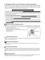
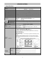
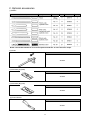
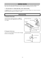
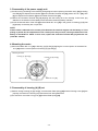
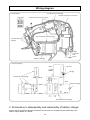
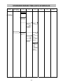
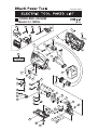
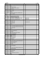
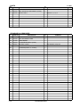
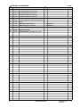
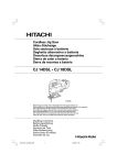
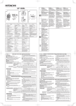
LIST No. H815
Jul. 2008
PRODUCT NAME
Hitachi 18 V Cordless Jig Saw
Model
C
CJ 18DSL
MARKETING OBJECTIVE
The new Model CJ 18DSL is a cordless jig saw equipped with a slide-type lithium-ion battery. The key features of
the Model CJ 18DSL are as follows.
(1) Highest cutting capacity in the class thanks to the high-performance motor
(2) Lightest in the class (2.4 kg, 5.3 lbs)
(3) Remaining battery indicator
(4) Equipped with lightweight and high-capacity (3.0 Ah) slide-type lithium-ion battery
We aim to expand our market share with the new cordless jig saw.
APPLICATIONS
• Cutting or cutting out shapes in various types of wood workpieces
• Cutting various types of metals such as mild steel, aluminum and copper
• Cutting various types of synthetic resin materials such as bakelite and vinyl chloride
• Cutting various decorative sheets and thin and soft construction materials
• Cutting stainless steel sheets
SELLING POINTS
[ NEW FEATURES ]
Highest cutting capacity in the class
Lightest in the class
Remaining battery indicator (switch panel)
Equipped with the new 18-V lithium-ion battery
(slide-type)
Tool-less blade changing system
LED lighting system
Powerful dust blowing
4-stage orbital action
Soft grip handle
SPECIFICATIONS AND PARTS ARE SUBJECT TO CHANGE FOR IMPROVEMENT.
International Sales Division
REMARK:
For more information about HANDLING INSTRUCTIONS, visit our website at:
http://www.hitachi-koki.com/manual_view_export/
Throughout this TECHNICAL DATA AND SERVICE MANUAL, a symbol(s) is(are) used in the place of
company name(s) and model name(s) of our competitor(s). The symbol(s) utilized here is(are) as follows:
Competitors
Symbols Utilized
C
Company Name
Model Name
Makita
BJV180
CONTENTS
Page
SELLING POINT DESCRIPTIONS -----------------------------------------------------------------------------------------1
SPECIFICATIONS --------------------------------------------------------------------------------------------------------------3
1. Specifications -----------------------------------------------------------------------------------------------------3
2. Optional accessories --------------------------------------------------------------------------------------------4
COMPARISONS WITH SIMILAR PRODUCTS--------------------------------------------------------------------------5
1. Specification comparisons--------------------------------------------------------------------------------------5
2. Cutting number comparisons per charge ------------------------------------------------------------------6
ORBITAL MECHANISM AND BLADE ------------------------------------------------------------------------------------7
1. Blade movement -------------------------------------------------------------------------------------------------7
2. Orbital position selection ---------------------------------------------------------------------------------------7
3. Blades --------------------------------------------------------------------------------------------------------------8
PRECAUTIONS IN SALES PROMOTION -------------------------------------------------------------------------------9
1. Safety instructions -----------------------------------------------------------------------------------------------9
2. Particular attention during sales promotion ------------------------------------------------------------- 11
REPAIR GUIDE --------------------------------------------------------------------------------------------------------------- 12
1. Precautions in disassembly and reassembly ----------------------------------------------------------- 12
2. Precautions in disassembly and reassembly of battery charger ----------------------------------- 19
STANDARD REPAIR TIME (UNIT) SCHEDULES ------------------------------------------------------------------- 20
Assembly diagram for CJ 18DSL
SELLING POINT DESCRIPTIONS
Highest cutting capacity in the class*
*: Based on our own research
The number of wood cutting operations per battery charge by the Model CJ 18DSL is 1.3 times higher than
C thanks to the efficient transmission of the cutting energy. For details, refer to "Cutting number
comparisons per charge" on page 8.
Lightest in the class*
*: Based on our own research
The Model CJ 18DSL is lightest in weight in the class.
Maker
HITACHI
C
Model
CJ 18DSL
CJ 18DL
Weight
2.4 kg (5.3 lbs)
2.4 kg (5.3 lbs)
2.8 kg (6.1lbs)
Remaining battery indicator (switch panel)
The Model CJ 18DSL is equipped with the remaining battery indicator (switch panel). The battery remaining
power can be easily checked by pressing the remaining battery level indicator switch while the Model
CJ 18DSL is stopping. Thus the battery can be charged in proper timing.
Indicator lamp
Remaining battery level
The battery remaining power is
enough.
Remaining battery level
indicator lamp
Remaining battery level
indicator switch
The battery remaining power is
a half.
The battery remaining power is
nearly empty. Charge the
battery immediately.
-1-
Equipped with the new 18-V lithium-ion battery (slide-type)
Each of the Model CJ 18DSL and the Type BSL 1830 lithium-ion battery is equipped with the overdischarge
protection circuit, overcurrent protection circuit and voltage monitoring circuit for each cell to prevent
reduction of the battery life due to overdischarge (overuse) or overcurrent (overload). Besides, the overheat
protection circuit is provided to protect the battery from overheating.
Precautions for use of the Type BSL 1830 lithium-ion battery
The Type BSL 1830 lithium-ion battery is equipped with a protective function that automatically stops output
to extend the battery life. The motor may stop automatically in any of the following cases (a), (b) and (c)
even if the switch is depressed continuously during operation. This is because the protective function is
activated. The battery is not faulty.
(a) The motor is stopped by the overdischarge protection circuit when the remaining battery level is low and
the battery voltage is decreased to about 12 V. In such case, charge the battery immediately.
(b) The motor is stopped by the overcurrent protection circuit when the load current of the Model CJ 18DSL
is about 75 A or higher. In such case, turn off the switch and turn on again. Then the motor is started. Be
careful not to overload the Model CJ 18DSL.
(c) The motor is stopped by the overheat protection circuit when the temperature of the cell in the battery is
80 °C or higher. In such case, remove the battery from the tool and cool it down completely in a wellventilated shaded area.
Tool-less blade changing system
The blade can be easily changed by opening/closing the lever. Usable blade is only the BOSCH's blade
whose thickness at the attaching portion is 1.5 mm or less or an equivalent blade having the same shape.
1) Open the lever fully. (Fig. )
2) Detach the blade from the blade holder.
Blade
3) Attach the new blade in the blade holder by pushing as far
as it will go. (Fig. )
Blade holder
4) Close the lever. (Fig. )
Lever
LED Lighting system
The Model CJ 18DSL is equipped with the LED light for illuminating the blade. To turn on the light, pull the
trigger. Release the trigger to turn off.
Powerful dust blowing
The Model CJ 18DSL is equipped with a dust blower mechanism that blows off dust by the air from the
motor cooling fan.
4-stage orbital action
The Model CJ 18DSL is equipped with the orbital mechanism that allows the blade to move up and down
and forward and backward. This mechanism makes the blade dig well into wood and other soft materials
and also discharges cutting chips well to achieve speedy cutting. For details, refer to “Blade movement” on
page 7.
Soft grip handle
The handle of the Model CJ 18DSL is widely covered with soft-touch elastomer (rubber-like soft resin). It is
slip-resistant and securely fits in the palm of a hand even if the gripping hand sweats.
-2-
SPECIFICATIONS
1. Specifications
Model
Capacity
No-load rotation speed
Length of stroke
Min. cutting radius
Type of motor
Type of switch
Max. cutting angle
LED light
Enclosure
Main body
Weight Charger
CJ 18DSL
Max. cutting thickness Wood
135 mm (5-5/16")
Mild steel
10 mm (3/8")
0 to 2,400 min-1
26 mm (1")
25 mm (1")
DC magnet motor with fan
Trigger switch with rotation selector and brake (with ON-OFF lock)
45° (right and left)
White LED
Housing ------- Glassfiber reinforced polycarbonate resin and elastomer
Gear holder -- Aluminum alloy die casting alloy
Battery --------- Glassfiber reinforced polycarbonate resin
Charger ------- ABS resin
2.4 kg (5.3 lbs) (including the battery)
0.6 kg (1.3 lbs)
(including the cord)
Overall length, overall height
and overall length
Battery
(Type BSL 1830)
Charger
(Model UC 18YRSL)
Standard
accessory
2LSCK
NN
277 mm x 213 mm x 76 mm
(10-29/32” x 8-3/8” x 2-63/64”)
Sealed cylindrical lithium-ion storage battery
Nominal voltage ------DC 18 V
Nominal life -----------Charging/discharging: Approx. 1,500 times
Nominal capacity ----3.0 Ah
Overcharge protection system:
(1) Battery voltage detection (- V system)
Battery temperature detection (dT/dt system)
(2) Battery surface temperature detection (thermostat or thermistor)
(3) 120-minute timer
(4) Stop current detection
Power input: 90 W
Charging time: Approx. 45 minutes [for Type BSL 1830 battery at 20°C
(68°F)]
Operable ambient temperature range: 0°C to 40°C (32°F to 104°F)
The maximum allowable temperature of the Type BSL 1830 battery is
50°C (122°F).
Indicated method of battery charging function
Charger (UC 18YRSL) --------------------------------------------- 1
Battery (BSL 1830) -------------------------------------------------- 2 (LSCK: 1)
Battery cover ---------------------------------------------------------- 1
Blade (No. 41) -------------------------------------------------------- 1
Splinter guard --------------------------------------------------------- 1
Chip cover ------------------------------------------------------------- 1
Plastic case ----------------------------------------------------------- 1
Without charger, battery, battery cover or plastic case
-3-
2. Optional accessories
(1) Blades
Blade shape
Application
Blade No.
Pitch
Code No.
NOTE: The standard blade No. 41 and the optional blade No. 21 have the same shape.
(2) Guide
Code No.
321593
(3) Sub base (A) (steel)
Code No.
321992
(4) Sub base (B) (resin)
Code No.
321993
(5) Dust collector
Code No.
321591
-4-
Per pkg.
COMPARISONS WITH SIMILAR PRODUCTS
(Superior specifications:
1. Specification comparisons
Maker
HITACHI
Model name
Cutting
capacity
CJ 18DL
135 mm (5-5/16”)
10 mm (3/8”)
0 to 2,400 min-1
25 mm (1”)
26 mm (1”)
45° (right and left)
White LED
Provided
Provided
Provided
Not provided
274 mm (10-25/32")
213 mm (8-3/8")
76 mm (2-63/64")
2.4 kg (5.3 lbs)
Li-ion
Plug-in type
135 mm (5-5/16”)
10 mm (3/8”)
0 to 2,600 min-1
Not indicated
26 mm (1”)
45° (right and left)
White LED
Provided
Provided
Not indicated
Not provided
255 mm (10-1/8")
208 mm (8-3/16")
73 mm (2-7/8")
2.8 kg (6.1 lbs.)
Li-ion
Slide type
Nominal
capacity
3.0 Ah
3.0 Ah
3.0 Ah
Nominal
voltage
18 V
18 V
18 V
Protection
circuit
Provided
Provided
Not indicated
Charging
time *1
45 min.
45 min.
22 min.
Wood
Mild steel
No-load speed
Min. cutting radius
Length of stroke
Max. cutting angle
LED light
Tool-less blade attachment
Soft grip handle
Changeover of impact energy
Remaing battery indicator
Length (A)
Dimensions
Height (B)
Width (C)
Weight
Type
Attachment
Battery
C
CJ 18DSL
135 mm (5-5/16”)
10 mm (3/8”)
0 to 2,400 min-1
25 mm (1”)
26 mm (1”)
45° (right and left)
White LED
Provided
Provided
Provided
Provided
277 mm (10-29/32")
213 mm (8-3/8")
76 mm (2-63/64")
2.4 kg (5.3 lbs)
Li-ion
Slide type
*1: Charging time may vary depending on the type of charger to be used.
A
B
C
-5-
)
2. Cutting number comparisons per charge
The number of cutting operations per battery charge may vary widely depending on hardness of wood or
mild steel, sharpness of the blade and other factors. Use the test results shown below for reference
purposes only.
Material
Maker
Wood
(24 mm thick
x 330 mm)
HITACHI
Mild steel
(2 mm thick
x 100 mm)
Model
0
Number of cutting operations per charge
20
40
60
80
100
120
CJ 18DSL
127
CJ 18DL
127
C
HITACHI
96
CJ 18DSL
40
CJ 18DL
40
30
C
-6-
ORBITAL MECHANISM AND BLADE
1. Blade movement
In the Model CJ 18DSL, the orbital mechanism moves the blade up-and-down and forward-and-backward.
The amount of fore-and-aft blade movement can be adjusted just by turning the change knob to any of the
four settings. The following table shows the modeled orbits of blade movement at each orbital position
(change knob position).
2. Orbital position selection
Selection of the most appropriate orbital position for each cutting job is essential to achieve the best
efficiency for cutting. However, as the best orbital position depends on such factors as hardness and
thickness of the workpiece, desired finish of the cut surface and so on, it is not practical to set a single,
simple standard for best orbital position selection. Table 1 can be used as a general guide for appropriate
orbital position selection based on various factors.
Table 1 General guide for appropriate orbital position selection
Orbital position
Factor
III
II
I
0
Material hardness
Soft material
Hard material
Material thickness
Thick
Thin
Cutting speed
Faster cutting
Slower cutting
Straight cutting or
Straight cutting
Curved cutting
curved cutting
Rough finish acceptable
Fine finishing
Surface finishing
(splintering, chipping acceptable)
Material stability
Unstable
Very stable
-7-
3. Blades
Proper blade selection is very important to obtain the maximum performance of the Model CJ 18DSL. The
table below, based on type and thickness of the material to be cut, can be used as a handy reference in
selecting the optimum blade.
NOTE :
The minimum cutting radius of No. 1 (Long), No.1 (Super long), No. 21, No. 22 and No. 41 blades is
100 mm.
-8-
PRECAUTIONS IN SALES PROMOTION
1. Safety instructions
In the interest of promoting the safest and most efficient use of the Model CJ 18DSL Cordless Jig Saw by
all of our customers, it is very important that at the time of sale, the salesperson carefully ensures that the
buyer seriously recognizes the importance of the contents of the Handling Instructions, and fully
understands the meaning of the precautions listed on the Caution Plate and the Name Plate attached to
each tool.
A. Handling instructions
Salespersons must be thoroughly familiar with the contents of the Handling Instructions in order to give
pertinent advice to the customer. In particular, they must have a thorough understanding of the precautions
for use of the cordless tools which are different from those of ordinary electric power tools.
(1) Before use, ensure that the unit is fully charged.
New units are not fully charged. Even if the units were fully charged at the factory, long periods of
inactivity, such as during shipping, cause the storage battery to lose its charge. Customers must be
instructed to fully charge the unit prior to use.
(2) Connect the charger to an AC power outlet only.
Use of any other power source (DC outlet, fuel powered generator, etc.) will cause the charger to
overheat and burn out.
(3) Do not use any voltage increasing equipment (transformer etc.) between the power source
and the charger.
If the charger is used with voltage higher than that indicated on the unit, it will not function properly.
(4) Conduct battery charging at an ambient temperature range of 0°C to 40°C (32°F to 104°F).
Special temperature sensitive devices are employed in the charger to permit rapid charging. Ensure
that customers are instructed to use the charger at the indicated ambient temperature range. At
temperature under 0°C (32°F) the thermostat will not function properly, and the storage battery may
be overcharged. At temperature over 40°C (104°F), the storage battery cannot be sufficiently
charged. The optimum temperature range is 20°C to 25°C (68°F to 77°F).
(5) The battery charger should not be used continuously.
At high ambient temperature, if over three storage batteries are charged in succession, the temperature
of the coils on the transformer will rise and there is a chance that the temperature fuse inserted in the
interior of the transformer will inadvertently melt. After charging one battery, please wait about 15
minutes before charging the next battery.
(6) Do not insert foreign objects into the air vents on the charger.
The charger case is equipped with air vents to protect the internal electronic components from
overheating. Caution the customer not to allow foreign materials, such as metallic or flammable objects,
to be dropped or inserted into the air vents. This could cause electrical shock, fire, or other serious
hazards.
(7) Do not attempt to disassemble the storage battery or the charger.
Special devices, such as a thermostat, are built into the storage battery and the charger to permit rapid
charging. Incorrect parts replacement and/or wiring will cause malfunctions which could result in fire or
other hazards. Instruct the customer to bring these units to an authorized service center in the event
repair or replacement is necessary.
(8) Disposal of the storage batteries
Ensure that all customers understand that storage batteries should be returned to the Hitachi power tool
sales outlet or the authorized service center when they are no longer capable of being recharged or
repaired. If thrown into a fire, the battery may explode.
(9) Keep the battery out of dust.
• Protect the battery from being covered with dust during operation.
• Protect the battery from being covered with dust accumulated on the Model CJ 18DSL during operation.
• Do not leave the battery in a dusty area when not in use.
• Remove dust from the battery and store it separating from metallic parts such as screws and nails.
-9-
B. Caution plate
(1) The following cautions are listed on the name plate attached to the main body of each tool.
[ For the U.S.A. and Canada ]
(2) The following cautions are listed on the name plate attached to each storage battery.
[ For Europe ]
[ For the U.S.A. and Canada ]
instruction manual
(3) The following cautions are listed on the name plate attached to the Model UC 18YRSL charger.
[ For the U.S.A. and Canada ]
CAUTION
• For safe operation, see instruction manual.
• Charge HITACHI rechargeable batteries types BSL 14
and BSL 18 series. Other types of batteries may burst
causing personal injury and damage.
• Charge between 32 °F and 104 °F. Rest 15 minutes
between the charging of batteries.
• Indoor use only.
• Replace defective cord immediately.
-10-
2. Particular attention during sales promotion
The cordless jig saw offers many advantages: it can be used in places where no power source is available,
the absence of a cord allows easy use, etc. However, in comparison with conventional AC type jig saws,
there are certain precautions which require particular attention. Salespersons must be thoroughly familiar
with the following points to properly advise the customer on the most efficient use of the tool.
A. Suggestions and precautions for the efficient use of the tool
(1) Appropriate cutting capacity of the Model CJ 18DSL
The Model CJ 18DSL is not capable of cutting dozens of workpieces like a conventional AC type jig saw
because it is a cordless jig saw powered by a battery. If the customer wishes to use the tool to cut many
workpieces in succession, please recommend that a spare battery should be kept available for use.
(2) Variation in amount of work possible per charge
Although the nominal capacity of the storage battery used with the Model CJ 18DSL is 3.0 Ah, the
actual capacity may vary within 10% of that value depending on the ambient temperature during use
and recharging, and the number of times the battery has been recharged.
It should also be noted that other factors which may have a bearing on the amount of work possible per
charge are the working conditions (ambient temperature, type and moisture content of the workpieces,
sharpness of the blade, etc.) and the operational skill of the user.
-11-
REPAIR GUIDE
Be sure to remove the storage battery from the main body before servicing. Inadvertent triggering of the
switch with the storage battery connected will result in danger of accidental turning of the motor.
1. Precautions in disassembly and reassembly
The [Bold] numbers in the description below correspond to the item numbers in the Parts List and the
exploded assembly diagram for the Model CJ 18DSL.
Disassembly
1. Removal of the base
Loosen the Hex. Socket Hd. Bolt M5 x 14 [50] and
remove the Gear Holder [34] together with the Base
Locker [49].
• Removal of the base
Gear Holder [34]
Base [48]
Base Locker [49]
Hex. Socket Hd. Bolt
M5 x 14 [50]
2. Removal of the lever
Loosen the Lever Bolt [19] and remove the Lever [18]
and the Lever Spring [17].
• Removal of the lever
Lever Spring [17]
Lever [18]
Lever Bolt [19]
-12-
3. Disassembly of housing (A).(B) set
(1) Remove the Guard Bar [7].
(2) Loosen the eight Tapping Screws (W/Flange) D4 x 20 (Black) [6] and open the housing.
(3) Remove the Plate Spring [24] from the housing.
(4) Loosen the Tapping Screw (W/Sp.Washer) D3 x 8 [9] and remove the Fence [8] from the housing.
(5) The other housing can then be removed from the main body. After disassembly, remove the two
O-rings (P-6) [5] from both sides of the housing.
• Removal of the housing
Tapping Screw (W/Flange)
Housing (A). (B) set [1]
D4 x 20 (Black) [6]
O-ring (P-6) [5]
Guard Bar [7]
Plate Spring [24]
Tapping Screw (W/Sp. Washer) D3 x 8 [9]
Fence [8]
4. Removal of the plunger and the blade holder
(1) Pull out the Pin D6 [23] from the Gear Holder [34], and remove the Plunger [26] and Plunger Holder (A)
[25].
(2) Loosen the Seal Lock Hex. Socket Hd. Bolt M3 x 6 [21] and the Seal Lock Hex. Socket Hd. Bolt M3 x 8
[20], and remove the Blade Holder [22].
(3) Pull out the Packing Cover [37], Packing [38] and Plunger Holder (B) [36] from the Plunger [26].
• Removal of the plunger and the blade holder
Gear Holder [34]
Plunger Holder (A) [25]
Pin D6 [23]
Seal Lock Hex. Socket Hd. Bolt
M3 x 6 [21]
Plunger [26]
Seal Lock Hex. Socket Hd. Bolt
M3 x 8 [20]
Plunger Holder (B) [36]
Blade Holder [22]
Packing Cover [37]
Packing [38]
-13-
5. Removal of the gear holder and the motor
(1) Pull out the Connecting Piece [28] and the Needle Bearing [29] from the Gear [30].
(2) Remove the Retaining Ring for D7 Shaft [27] from the tip of the spindle.
(3) Remove the Gear [30], Balance Weight [31], Orbital Cam [32] and Washer (A) [33] in order.
(4) Pull out the Ball Bearing 608VVC2PS2L [15] and the Motor DC 18 V [16] press-fitted in the Gear Holder
[34].
• Removal of the gear holder and the motor
Connecting
Piece [28]
Needle Bearing [29]
Ball Bearing
608VVC2PS2L [15]
Washer (A) [33]
Retaining Ring
for D7 Shaft [27]
Gear Holder [34]
(Motor DC 18 V [16])
Gear [30]
Balance Weight [31]
Orbital Cam [32]
6. Removal of the DC-speed control switch and the wiring of the motor
(1) Remove the Pushing Button [3] and the Switch Ass’y [51] (including the LED [2], DC-Speed Control
Switch [4] and terminal) from the housing.
(2) Cut the lead wire (red) and the lead wire (black) wired from the LED [2] to the DC-Speed Control Switch
[4].
(3) Cut the lead wire (red) and the lead wire (black) wired from the Motor DC 18 V [16] to the DC-Speed
Control Switch [4].
(4) Cut the lead wire (blue) and the lead wire (brown) wired from the DC-Speed Control Switch [4] to the
terminal.
• Removal of the DC-speed control switch and the wiring of the motor
Pushing Button [3]
LED [2]
DC-Speed Control Switch [4]
(Motor DC 18 V [16])
Controller Terminal Set [13]
-14-
7. Removal of the roller holder
(1) Remove the two Retaining Rings (E-Type) for D3 Shaft [44] from the Pin [41].
(2) Pull out the Needle Roller [39] press-fitted in the Gear Holder [34] and remove the Roller Holder [40].
(3) Remove the Needle Roller [39] from the Gear Holder [34].
• Removal of the roller holder
Needle Roller [39]
Gear Holder [34]
Roller Holder [40]
Pin [41]
Retaining Ring (E-Type) for D3 Shaft [44]
8. Removal of the change knob
(1) Remove the Retaining Ring (E-Type) for D5 Shaft [35] and remove the Change Knob [45], Spring (C)
[46] and Steel Ball D3.97 [47].
(2) Be careful not to lose Spring (C) [46] and the Steel Ball D3.97 [47].
• Removal of the change knob
Retaining Ring (E-Type)
for D5 Shaft [35]
Steel Ball D3.97 [47]
Spring (C) [46]
Change Knob [45]
-15-
Reassembly
Reassembly can be accomplished by following the disassembly procedures in reverse. However, special
attention should be given to the following items.
1. Mounting the change knob
Mount Spring (C) [46] and the Steel Ball D3.97 [47] into the Change Knob [45] as shown in the figure
below.
• Mounting the change knob
Spring (C) [46]
Steel Ball D3.97 [47]
Change Knob [45]
Retaining Ring (E-Type)
for D5 Shaft [35]
2. Mounting the gear holder
Before mounting the Roller Holder [40], be sure to insert the Needle Roller [39] into the designated position
of the Gear Holder [34] because the Needle Roller [39] cannot be inserted after mounting the Roller Holder
[40].
• Mounting the gear holder
Gear Holder [34]
Needle Roller [39]
Roller Holder [40]
-16-
3. Reassembly of the power supply unit
(1) Perform wiring according to the following wiring diagram when replacing the Switch Ass'y [51] (including
the LED [2], DC-Speed Control Switch [4] and Controller Terminal Set [13]), Motor DC 18 V [16], LED
[2], DC-Speed Control Switch [4] and Controller Terminal Set [13].
(2) Mount the Controller Terminal Set [13] aligning with the locking rib of the housing. At this time, pay
attention to the direction of the battery terminal and the remaining battery indicator.
(3) Push the internal wires of the LED [2] and the Motor DC 18 V [16] in the groove of Housing (A).(B) Set
[1] properly so that they are not pinched.
NOTE:
If black oxide is adhered to the contact point between the terminal support and the battery or if the
plating is peeled off, the temperature of the contact point may increase, causing malfunction of the
battery or the Model CJ 18DSL. In such case, replace the Controller Terminal Set [13] with new one
(Code No. 330070).
4. Mounting the motor
(1) Mount the Motor DC 18 V [16] to Housing (A).(B) Set [1] aligning the concave portion of the Motor DC
18 V [16] with the convex portion of Housing (A).(B) Set [1].
• Mounting the motor
Housing (A). (B) Set [1]
Housing (A). (B) Set [1]
Motor DC 18 V [16]
Motor DC 18 V [16]
5. Reassembly of housing (A).(B) set
(1) Before closing Housing (A).(B) Set [1], check that the Plate Spring [24] and the Packing Cover [37] are
properly mounted in the housing to prevent them from being deformed.
(2) Do not fail to mount the O-ring (P-6) [5] and the Plate Spring [24].
-17-
Application of lubricant
Apply 20 g of Shell Albania (RL3) grease to the following parts.
• Pinion of the Motor DC 18 V [16]
• Tooth flanks and outer circumference of the shank of the Gear [30]
• Sliding section of the Balance Weight [31] (including the inner surface of the oval hole)
• Sliding section of the Orbital Cam [32] (including the inner surface of the oval hole)
• Sliding section of Washer (A) [33]
• Sliding section of Plunger Holder (A) [25]
Apply 10 g of Molub-Alloy (777-1) grease to the inner and outer circumferences of the Connecting Piece
[28].
Apply 2 g of grease (BC-4) to the sliding section of the Plunger [26] and the sliding section and the inside of
the Plate Spring [24].
Screw tightening torque
• Tapping Screw (W/Flange) D4 x 20 (Black) [6] ------------------------------- : 2.0 ± 0.5 N٠m (20 ± 5 kgf٠cm)
• Tapping Screw (W/Sp. Washer) D3 x 8 [9] ------------------------------------- : 1.5 ± 0.4 N٠m (15 ± 4 kgf٠cm)
• Lever Bolt [19]------------------------------------------------------------------------- : 2.5 ± 0.5 N٠m (25 ± 5 kgf٠cm)
• Seal Lock Hex. Socket Hd. Bolt M3 x 8 [20] ----------------------------------- : 2.5 ± 0.5 N٠m (25 ± 5 kgf٠cm)
• Seal Lock Hex. Socket Hd. Bolt M3 x 6 [21] ----------------------------------- : 2.5 ± 0.5 N٠m (25 ± 5 kgf٠cm)
• Machine Screw (W/Washer) M4 x 8 (Black) [42] ----------------------------- : 2.0 ± 0.5 N٠m (20 ± 4 kgf٠cm)
• Hex. Socket Hd. Bolt M5 x 14 [50] ----------------------------------------------- : 3.9 to 5.8 N٠m (40 to 60 kgf٠cm)
Checking after reassembly
Check the following after reassembly.
(1) Check that the switching operation of the DC-Speed Control Switch [4] and the Pushing Button [3] is
smooth.
(2) Check that the LED [2] lights by depressing the trigger of the DC-Speed Control Switch [4].
(3) Check that the stroke speed changes depending on the depressing amount of the trigger of the DCSpeed Control Switch [4].
(4) Check that the blade can be attached securely.
(5) Check that the remaining battery indicator lamp lights by pressing the remaining battery indicator switch
and goes off by releasing your finger from the remaining battery indicator switch.
No-load current
No-load current: 7.5 A or lower (18 V)
-18-
Wiring diagram
• Wiring diagram
DC-Speed Control Switch [4]
Push the internal wire in the groove.
Push the internal wire in the groove.
View from A
Push the internal wire in the groove.
Controller Terminal
Set [13]
Push the
internal wire
in the
groove.
LED [2]
Motor DC 18 V [16]
• Connecting diagram
LED ass’y
Indication unit
(Black)
(Yellow)
LED [2]
Controller Terminal Set [13]
(Red)
(Red)
(White)
(Red)
(White)
Motor DC 18 V [16]
Reversing unit
Control unit
(Red)
Protector PB
Terminal
(Red)
(Black)
(White)
DC-Speed Control Switch [4]
2. Precautions in disassembly and reassembly of battery charger
Refer to the Technical Data and Service Manual for precautions in disassembly and reassembly of the
battery charger Model UC 18YRSL.
-19-
STANDARD REPAIR TIME (UNIT) SCHEDULES
MODEL
Variable
Fixed
10
20
30
Motor Ass’y
Ball Bearing
(608VV)
DC-Speed
Control Switch
Controller
Housing
(A). (B) Set
Work Flow
CJ 18DSL
Base
Base Locker
General Assembly
Fence
Lever Spring
Lever
Gear Holder
Ass’y
Roller Holder
Ass’y
Change Knob
Spring (C)
Steel Ball
Connecting
Piece
Needle
Bearing
Gear
Balance
Weight
Orbital Cam
Washer (A)
Plunger
Holder (A)
Plunger
Plunger
Holder (B)
Packing Cover
Packing
Blade Holder
-20-
40
50
60 min.
LIST NO. H815
CORDLESS JIG SAW
Model CJ 18DSL
501
502
(E1)
504
503
505
6
11
507
5
506
4
3
1
2
51
12
13
2
4
12
13
14
7
8
9
17
10
25
15
18
23
26
27
16
28
24
29
19
30
31
20
32
21
36
33
22
37
34
38
35
39
41
42
43
40
44
47
46
48
45
49
50
PARTS
ITEM
NO.
CJ 18DSL
CODE NO.
DESCRIPTION
NO.
USED
1
330-071
HOUSING (A). (B) SET
1
2
328-336
LED
1
3
319-760
PUSHING BUTTON
1
4
328-335
DC-SPEED CONTROL SWITCH
1
5
984-528
O-RING (P-6)
4
6
301-653
TAPPING SCREW (W/FLANGE) D4X20 (BLACK)
8
7
328-349
GUARD BAR
1
8
321-592
FENCE
1
9
984-327
TAPPING SCREW (W/SP. WASHER) D3X8
1
HITACHI LABEL
1
10
11
12
959-140
NAME PLATE
1
CONNECTOR 50091 (10 PCS.)
1
REMARKS
13
330-070
CONTROLLER TERMINAL SET
1
*
14
330-068
BATTERY BSL 1830 (EUROPE, AUS, NZL)
2
INCLUD. 505
*
14
330-067
BATTERY BSL 1830 (USA, CAN)
1
INCLUD. 505
15
608-VVM BALL BEARING 608VVC2PS2L
1
*
16
328-361
MOTOR DC 18V
1
*
16
328-739
MOTOR DC 18V
1
17
321-580
LEVER SPRING
1
18
328-347
LEVER
1
19
328-348
LEVER BOLT
1
20
325-241
SEAL LOCK HEX. SOCKET HD. BOLT M3X8
1
21
325-077
SEAL LOCK HEX. SOCKET HD. BOLT M3X6
1
22
325-076
BLADE HOLDER
1
23
983-564
PIN D6
1
24
325-071
PLATE SPRING
1
25
325-070
PLUNGER HOLDER (A)
1
26
328-343
PLUNGER
1
27
994-251
RETAINING RING FOR D7 SHAFT
1
28
328-342
CONNECTING PIECE
1
29
325-242
NEEDLE BEARING
1
30
328-341
GEAR
1
31
328-340
BALANCE WEIGHT
1
32
328-339
ORBITAL CAM
1
33
957-540
WASHER (A)
1
34
328-328
GEAR HOLDER
1
35
673-489
RETAINING RING (E-TYPE) FOR D5 SHAFT
1
36
328-344
PLUNGER HOLDER (B)
1
37
328-346
PACKING COVER
1
38
328-345
PACKING
1
39
328-329
NEEDLE ROLLER
1
40
328-330
ROLLER HOLDER
1
41
328-331
PIN
1
42
315-500
MACHINE SCREW (W/WASHER) M4X8 (BLACK)
1
43
321-576
RUBBER BUSHING
1
44
872-971
RETAINING RING (E-TYPE) FOR D3 SHAFT
2
45
328-332
CHANGE KNOB
1
46
982-454
SPRING (C)
1
47
959-155
STEEL BALL D3.97 (10 PCS.)
1
48
321-573
BASE
1
-2-
*ALTERNATIVE PARTS
FOR USA, CAN
7 - 08
PARTS
ITEM
NO.
CJ 18DSL
CODE NO.
DESCRIPTION
NO.
USED
49
321-575
BASE LOCKER
1
50
949-665
HEX. SOCKET HD. BOLT M5X14 (10 PCS.)
1
51
330-069
SWITCH ASS'Y
1
REMARKS
INCLUD. 2, 4, 12, 13
STANDARD ACCESSORIES
ITEM
NO.
*
CODE NO.
DESCRIPTION
NO.
USED
501
328-352
CHIP COVER
1
502
944-458
HEX. BAR WRENCH 4MM
1
503
321-590
TABLE INSERT
1
504
879-357
JIG SAW BLADE NO.41 (5 PCS.)
1
505
329-897
BATTERY COVER
1
506
328-351
CASE
1
CHARGER (MODEL UC 18YRSL)
1
507
7 - 08
*ALTERNATIVE PARTS
REMARKS
FOR EUROPE, AUS, NZL
-3-
OPTIONAL ACCESSORIES
ITEM
NO.
CODE NO.
CJ 18DSL
DESCRIPTION
NO.
USED
REMARKS
601
879-336
JIG SAW BLADES NO.11 (5 PCS.)
1
602
879-337
JIG SAW BLADES NO.12 (5 PCS.)
1
603
879-338
JIG SAW BLADES NO.15 (5 PCS.)
1
604
879-339
JIG SAW BLADES NO.16 (5 PCS.)
1
605
879-340
JIG SAW BLADES NO.21 (5 PCS.)
1
606
879-341
JIG SAW BLADES NO.22 (5 PCS.)
1
607
963-400
JIG SAW BLADES NO.97 FOR STAINLESS (5PCS)
1
608
321-593
GUIDE
1
609
321-992
SUB BASE (A) SET (STEEL)
1
INCLUD. 611
610
321-993
SUB BASE (B) SET (PLASTIC)
1
INCLUD. 611
611
321-996
SPECIAL BOLT
4
612
321-591
DUST COLLECTOR
1
613
325-149
GREASE (MOLUB-ALLOY NO.777-1) 75G
1
-4-
*ALTERNATIVE PARTS
Printed in Japan
(080709N)
7 - 08