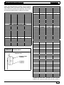
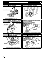
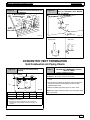
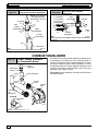
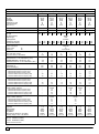
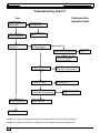
1
ÁÁÁÁÁÁÁÁÁÁÁÁÁÁÁÁÁÁÁÁÁÁÁÁÁÁÁÁ
ÁÁÁÁÁÁÁÁÁÁÁÁÁÁÁÁÁÁÁÁÁÁÁÁÁÁÁÁ
ÁÁÁÁÁÁÁÁÁÁÁÁÁÁÁÁÁÁÁÁÁÁÁÁÁÁÁÁ
MULTI POSITION
ÁÁÁÁÁÁÁÁÁÁÁÁÁÁÁÁÁÁÁÁÁÁÁÁÁÁÁÁ
ÁÁÁÁÁÁÁÁÁÁÁÁÁÁÁÁÁÁÁÁÁÁÁÁÁÁÁÁ
90% SINGLE STAGE
ÁÁÁÁÁÁÁÁÁÁÁÁÁÁÁÁÁÁÁÁÁÁÁÁÁÁÁÁ
ÁÁÁÁÁÁÁÁÁÁÁÁÁÁÁÁÁÁÁÁÁÁÁÁÁÁÁÁ
GAS FURNACES
ÁÁÁÁÁÁÁÁÁÁÁÁÁÁÁÁÁÁÁÁÁÁÁÁÁÁÁÁ
ÁÁÁÁÁÁÁÁÁÁÁÁÁÁÁÁÁÁÁÁÁÁÁÁÁÁÁÁ
ÉÉÉ
ÉÉÉÉÉÉÉÉÉÉÉÉÉÉ
ÉÉÉÉÉÉÉÉ
ÉÉÉÉÉÉÉÉÉÉÉÉÉÉÉÉÉÉÉÉ
ÉÉÉÉÉÉÉÉÉÉÉÉÉÉÉÉÉÉÉÉ
ÉÉÉÉ
ÉÉ
ÉÉÉÉ
ÉÉ
ÉÉÉ
ÉÉÉÉ
ÉÉÉ
ÉÉÉ
ÉÉÉÉÉÉÉÉÉÉÉÉÉÉÉÉÉÉÉ
ÉÉÉÉÉÉÉÉÉÉÉÉÉÉÉÉÉÉÉ
N9MP1, N9MP2 & *9MPD
* Denotes brand H, C, T
This manual supports single stage “C” series and later condensing gas furnaces
Manufactured by:
Part Number
440 08 2011 00
2/2006
© 2006 International Comfort Products LLC
N9MP1 − Indoor combustion air (1 pipe only)
N9MP2 − Direct Vent ONLY (2 pipe only)
*9MPD − Dual Certified Venting (1 or 2 pipes)
* Denotes Brand (T, C or H)
Single Stage Multi Position Furnace
Service Manual
TABLE OF CONTENTS
1. INTRODUCTION . . . . . . . . . . . . . . . . . . . . . . . . . . . . . . . . . . . . . . . . . . . . . . . . . . . . . . . . . . . .
2. UNIT IDENTIFICATION . . . . . . . . . . . . . . . . . . . . . . . . . . . . . . . . . . . . . . . . . . . . . . . . . . . . .
3. FURNACE THEORY OF OPERATION . . . . . . . . . . . . . . . . . . . . . . . . . . . . . . . . . . . . . . . .
4. ELECTRICAL SUPPLY . . . . . . . . . . . . . . . . . . . . . . . . . . . . . . . . . . . . . . . . . . . . . . . . . . . . . .
5. INTERLOCK SWITCH . . . . . . . . . . . . . . . . . . . . . . . . . . . . . . . . . . . . . . . . . . . . . . . . . . . . . .
6. GAS SUPPLY . . . . . . . . . . . . . . . . . . . . . . . . . . . . . . . . . . . . . . . . . . . . . . . . . . . . . . . . . . . . . .
7. L.P. PRESSURE SWITCH . . . . . . . . . . . . . . . . . . . . . . . . . . . . . . . . . . . . . . . . . . . . . . . . . . .
8. HONEYWELL VR8205S GAS VALVE . . . . . . . . . . . . . . . . . . . . . . . . . . . . . . . . . . . . . . . . .
9. HIGH ALTITUDE OPERATION . . . . . . . . . . . . . . . . . . . . . . . . . . . . . . . . . . . . . . . . . . . . . . .
10. CHECKING TEMPERATURE RISE . . . . . . . . . . . . . . . . . . . . . . . . . . . . . . . . . . . . . . . . . .
11. ROOM THERMOSTATS . . . . . . . . . . . . . . . . . . . . . . . . . . . . . . . . . . . . . . . . . . . . . . . . . . . .
12. CONTROL WIRING . . . . . . . . . . . . . . . . . . . . . . . . . . . . . . . . . . . . . . . . . . . . . . . . . . . . . . .
13. TWINNING KITS . . . . . . . . . . . . . . . . . . . . . . . . . . . . . . . . . . . . . . . . . . . . . . . . . . . . . . . . . .
14. LIMIT SWITCHES . . . . . . . . . . . . . . . . . . . . . . . . . . . . . . . . . . . . . . . . . . . . . . . . . . . . . . . . .
15. PRESSURE SWITCHES . . . . . . . . . . . . . . . . . . . . . . . . . . . . . . . . . . . . . . . . . . . . . . . . . . .
16. HIGHER/LOWER NEGATIVE PRESSURES . . . . . . . . . . . . . . . . . . . . . . . . . . . . . . . . . .
17. VENT/COMBUSTION AIR PIPING . . . . . . . . . . . . . . . . . . . . . . . . . . . . . . . . . . . . . . . . . .
18. STANDARD VENT TERMINATION . . . . . . . . . . . . . . . . . . . . . . . . . . . . . . . . . . . . . . . . . .
19. CONCENTRIC VENT TERMINATION . . . . . . . . . . . . . . . . . . . . . . . . . . . . . . . . . . . . . . . .
20. COMBUSTION BLOWER . . . . . . . . . . . . . . . . . . . . . . . . . . . . . . . . . . . . . . . . . . . . . . . . . .
21. CONDENSATE DRAIN TRAP . . . . . . . . . . . . . . . . . . . . . . . . . . . . . . . . . . . . . . . . . . . . . . .
22. SEQUENCE OF OPERATION . . . . . . . . . . . . . . . . . . . . . . . . . . . . . . . . . . . . . . . . . . . . . .
23. CHECKING FLAME CURRENT . . . . . . . . . . . . . . . . . . . . . . . . . . . . . . . . . . . . . . . . . . . . .
24. CAPACITORS . . . . . . . . . . . . . . . . . . . . . . . . . . . . . . . . . . . . . . . . . . . . . . . . . . . . . . . . . . . .
25. BLOWER ASSEMBLY . . . . . . . . . . . . . . . . . . . . . . . . . . . . . . . . . . . . . . . . . . . . . . . . . . . . .
BLOWER PERFORMANCE DATA . . . . . . . . . . . . . . . . . . . . . . . . . . . . . . . . . . . . . . . . . . . . . .
WIRING DIAGRAM . . . . . . . . . . . . . . . . . . . . . . . . . . . . . . . . . . . . . . . . . . . . . . . . . . . . . . . . . . .
TECHNICAL SERVICE DATA (N9MP1 C1) . . . . . . . . . . . . . . . . . . . . . . . . . . . . . . . . . . . . . . .
TECHNICAL SERVICE DATA (N9MP2 C1) . . . . . . . . . . . . . . . . . . . . . . . . . . . . . . . . . . . . . . .
TECHNICAL SERVICE DATA (*9MPD C1) . . . . . . . . . . . . . . . . . . . . . . . . . . . . . . . . . . . . . .
TROUBLE SHOOTING GUIDE . . . . . . . . . . . . . . . . . . . . . . . . . . . . . . . . . . . . . . . . . . . . . . . . .
DIAGNOSTIC CODE SECTION . . . . . . . . . . . . . . . . . . . . . . . . . . . . . . . . . . . . . . . . . . . . . . . .
TROUBLE SHOOTING CHART #1 . . . . . . . . . . . . . . . . . . . . . . . . . . . . . . . . . . . . . . . . . . . . . .
TROUBLE SHOOTING CHART #2 . . . . . . . . . . . . . . . . . . . . . . . . . . . . . . . . . . . . . . . . . . . . . .
TROUBLE SHOOTING CHART #3 . . . . . . . . . . . . . . . . . . . . . . . . . . . . . . . . . . . . . . . . . . . . . .
INDEX . . . . . . . . . . . . . . . . . . . . . . . . . . . . . . . . . . . . . . . . . . . . . . . . . . . . . . . . . . . . . . . . . . . . . .
2
3
3
4
5
5
10
11
11
11
12
12
13
13
14
16
17
17
21
22
23
24
26
26
26
29
30
31
32
33
34
35
36
37
38
40
Service Manual
Single Stage Multi Position Furnace
INTRODUCTION
This service manual is designed to be used in conjunction
with the installation manual and/or technical support manual provided with each furnace.
These furnaces represent the very latest in high efficiency
gas furnace technology. Consequently, they incorporate
the use of certain controls that contain highly sophisticated
electronic components which are not user serviceable.
Therefore, it is essential that only competent, qualified, service personnel attempt to install, service, or maintain this
product.
This Service manual was written to assist the professional
HVAC service technician to quickly and accurately diagnose and repair any malfunction of this product.
This service manual covers the following models;
*9MPD− − − − − − C or later, *9MP1 − − − − − − C or
later and *9MP2 − − − − − − C or later models. The overall
operation of all of these models is essentially the same.
This manual, therefore, will deal with all subjects in a general nature (I.E. all text will pertain to all models) unless that
subject is unique to a particular model or family, in which
case it will be so indicated.
It will be necessary then for you to accurately identify the
unit you are servicing, so you may be certain of a proper
diagnosis and repair. (See Unit Identification, Page 3)
SAFETY REQUIREMENTS
Recognize safety information. This is the safety−alert symbol
the potential for personal injury.
!
. When you see this symbol on the furnace and in instructions manuals be alert to
Understand the signal words DANGER, WARNING, or CAUTION. These words are used with the safety−alert symbol. DANGER identifies the most
serious hazards, those that will result in severe personal injury or death. WARNING signifies a hazard that could result in personal injury or death.
CAUTION is used to identify unsafe practices that could result in minor personal injury or product and property damage. NOTE is used to highlight
suggestions that will result in enhanced installation, reliability, or operation.
Installing and servicing heating equipment can be hazardous due to gas and electrical components. Only trained and qualified personnel should
install, repair, or service heating equipment.
Untrained service personnel can perform basic maintenance functions such as cleaning and replacing air filters. All other operations must be performed by trained service personnel. When working on heating equipment, observe precautions in the literature, on tags, and on labels attached to or
shipped with the unit and other safety precautions that may apply.
Follow all safety codes. In the United States, follow all safety codes including the current edition National Fuel Gas Code (NFGC) ANSI
Z223.1−2002/NFPA No. 54−2002. In Canada, refer to the current edition of the National Standard of Canada Natural Gas and Propane Installation
Code (NSCNGPIC) CSA B149.1−05. Wear safety glasses and work gloves. Have fire extinguisher available during start−up and adjustment procedures and service calls.
These instructions cover minimum requirements and conform to existing national standards and safety codes. In some instances, these instructions
exceed certain local codes and ordinances, especially those that may not have kept up with changing residential construction practices. We require
these instructions as a minimum for a safe installation.
c
4
International Comfort Products LLC
Lewisburg, TN 37091
440 08 2011 00
Service Manual
Single Stage Multi Position Furnace
UNIT IDENTIFICATION
The unit’s rating plate contains important information for the
service technician. It also lists the complete Model
Manufacturing and Serial Numbers.
These complete numbers are required to obtain correct re-
placement parts (example, in certain model families a unit
having a MARKETING REVISION of “C” is likely to be
equipped with one or more different components.
MODEL NUMBER IDENTIFICATION GUIDE
*
9
MP
D
0 75
B
12
C
Brand Identifier
1
Engineering Rev.
T = Tempstar
Denotes major changes
C = Comfortmaker
Marketing Digit
H = Heil
Denotes major change
A = Arcoaire
N = Non−Brand Specific (Generic)
Cooling Airflow
08 = 800 CFM
Brand Identifier
8 = Non−Condensing, 80+% Gas Furnace
12 = 1200 CFM
9 = Condensing, 90+% Gas Furnace
14 = 1400 CFM
16 = 1600 CFM
Installation Configuration
UP = Upflow
DN = Downflow
HZ = Horizontal
UH = Upflow/Horizontal
20 = 2000 CFM
DH = Downflow/Horizontal
MP = Multiposition, Upflow/Downflow/Horizontal
Cabinet Width
B = 15.5″ Wide
Major Design Feature
1 = One (Single) Pipe
N = Single Stage
F = 19.1″ Wide
2 = Two Pipe
P = PVC Vent
J = 22.8″ Wide
D = 1 or 2 Pipe
T = Two Stage
L = 24.5″ Wide
L = Low NOx
V = Variable Speed
Input (Nominal MBTUH)
FURNACE THEORY OF OPERATION
The high efficiencies and lower profile (compared to past
series) of this furnace have been obtained using design
techniques not typical of traditional furnace designs. A brief
description of these new design techniques and the purpose they serve follows.
1. Reducing the height of the furnace while maintaining
the high efficiency of pervious models required maintaining the surface area of the heat exchanger and
yet minimizing the overall size.
The design required to achieve these results is the “SERPENTINE” design, wherein the flue gasses must follow a
serpent shaped passage through the heat exchanger via
convection.
This “Serpentine” path is resistive to normal convective
flow, and requires that a partial vacuum be created at the
outlet of the heat exchanger to maintain the flow of flue
products through the heat exchanger.
2. The serpentine heat exchanger design does not lend
itself well to the ribbon type, or slotted port type burner
found in more traditional design furnaces for the following reasons:
A. The secondary combustion airflows at right angles
to the burner flame, making it likely to “pull” the
flame off a ribbon or slotted port type burner.
440 08 2011 00
B. The flame “height” of a ribbon or slotted port type
burner would make it difficult (if not impossible) to
prevent impingement of the flame on the heat exchanger surfaces whole maintaining the low profile
heat exchanger.
For these reasons, an “INSHOT” type burner is used in this
series. The inshot burner (also called a “jet” burner) fires a
flame straight out its end. This burner is designed to fire into
a tube style heat exchanger, making it an ideal application
in the tube−like passages of the serpentine heat exchanger.
3. In order to extract the maximum amount of heat possible from the flue gasses, a secondary heat exchanger (condenser) is connected to the outlet of the
primary heat exchanger. This condenser removes
additional heat from the flue gasses, causing their
temperature to drop below dew point. This results in
the forming of condensation (water) which then must
be routed to a drain.
4. The placement of the secondary heat exchanger at
the outlet of the primary heat exchanger creates additional resistance to the flow of gasses.
5. To overcome the resistance to convective flow of the
Primary and Secondary heat exchangers requires the
use of an Induced Draft Combustion Blower Assembly.
5
Service Manual
Single Stage Multi Position Furnace
6. The Combustion Blower Assembly is mounted on the
outlet side of the Secondary heat exchanger, This
blower creates a partial vacuum (negative pressure)
within the heat exchangers drawing the flue products
out of the furnace.
7. A pressure switch (Air Proving Switch) is used as a
safety device that prevents the ignition system from
firing the furnace until it senses that a proper draft has
been established through the furnace.
SEQUENCE OF OPERATION − HEATING
Refer to the ignition control section for sequence of operation.
ELECTRICAL SUPPLY
WARNING
ELECTRICAL SHOCK HAZARD.
Failure to turn off power could result in death or
personal injury.
Turn OFF electrical power at fuse box or service
panel before making any electrical connections
and ensure a proper ground connection is made
before connecting line voltage.
Electrical Connections
Figure 1
NOTE: Junction Box can be
mounted to either the left or right
side.
115V. 60 Hz
HOT
NEUT.
!
W
BK
G
O
N
Connection
Box
SUPPLY CIRCUIT
The furnace cannot be expected to operate correctly unless
it is properly connected (wired) to an adequately sized
single branch circuit. Line voltage wires should conform to
temperature limitation of 63° F (35° C) rise and be sized for
the unit maximum amps stated on the rating plate. Add the
full load amps for potential field − installed accessories that
would receive power from the furnace control. Consult NEC
or local codes for proper wire and circuit sizing.
O
FF
Ground
Low Voltage
Terminal Board
Models may
have 1 or 2
pressure
switches
R
G
W
Y
G
W
R
G
SUPPLY VOLTAGE
Supply voltage to the furnace should be a nominal 115 volts.
It MUST be between 104 volts and 127 volts. Supply voltage to the furnace should be checked WITH THE FURNACE IN OPERATION. Voltage readings outside the specified range can be expected to cause operating problems.
Their cause MUST be investigated and corrected.
ELECTRICAL GROUND
Proper grounding of the electrical supply to THE FURNACE
IS REQUIRED for safety and operational reasons.
POLARITY
CORRECT POLARITY of the line voltage supply to the furnace is also required for safety and operational reasons.
The furnace control MUST have proper line voltage polarity
to operate properly.
6
25−24−90−2
NOTE: 115 VAC/60Hz/single−phase
Operating voltage range*: 127 VAC max, 104 VAC min.
* Permissible limits of voltage at which unit will operate satisfactorily
CHECKING GROUNDING AND POLARITY
Grounding may be verified as follows:
1. Turn the power supply “OFF”.
2. Using an Ohmmeter check for continuity between the
Neutral (white) wire and Ground wire (green) of the
supply circuit.
3. With the Ohmmeter set on the R x 1 scale, the reading should be zero Ohms.
4. A zero Ohm reading indicates that the neutral is
grounded back to the main panel.
440 08 2011 00
Service Manual
Single Stage Multi Position Furnace
5. An alternate check would be to check for continuity
from the Neutral to a cold water pipe, (Pipe must be
metal, and must have a continuous, uninterrupted
connection to ground) or to a continuous, uninterrupted connection to ground) or to a driven ground
rod.
6. Any readings other than zero Ohms would indicate
a poor ground, or no ground.
4. Check for Voltage between the Neutral (White) wire
and Ground wire of the supply circuit.
5. Reading should be zero Volts. (if line voltage is read,
polarity is reversed)
6. A zero Volt reading indicates there is no voltage potential on Neutral wire.
7. Double check by checking for voltage between the
Hot (Black) wire and Ground wire of the supply circuit.
Polarity may be verified as follows:
1. Turn the power supply “ON”.
2. Using a Voltmeter check for voltage between the Hot
(Black) and Neutral (White) wire of supply circuit.
3. Reading should be Line (Supply) Voltage.
8. Reading should be Line (supply) Voltage. (if zero
volts is read, there is no ground, or polarity is reversed.)
INTERLOCK SWITCH
The blower compartment door of all models is equipped
with an interlock switch. (See Figure 2) This switch is “Normally Open” (closes when the door is on the furnace) and
interrupts furnace operation when the door is open. This interlock switch is a safety device, and SHOULD NEVER BE
BY−PASSED.
Since this is a single pole switch, (breaking only one side of
the line) proper line polarity is essential to insure that furnace components are not “HOT” when switch is open. (See
Checking Grounding and Polarity)
Figure 2
Typical Interlock Switch
10−12−96
GAS SUPPLY
An adequately sized gas supply to the furnace is required
for proper operation. Gas piping which is undersized will not
provide sufficient capacity for proper operation. Piping
should be sized in accordance with accepted industry standards. Refer to NFGC and ANSI Z223.1 for proper gas pipe
size.
NATURAL GAS
Inlet (Supply) pressure to the furnace should be checked (at
the gas valve) with ALL OTHER GAS FIRED APPLIANCES
OPERATING. Inlet (Supply) pressure to the furnace under
these conditions MUST be within minimum and maximum
values listed on rating plate. If the inlet pressure is less, it
may be an indication of undersized piping or regulator problems.
L.P. GAS
Inlet (Supply) pressure to the furnace should be checked in
the same manner as for Natural Gas, however with L.P.
Gas, the inlet pressure MUST be a minimum of 11″ W.C. If
this cannot be obtained, problems are indicated in either the
regulator or pipe sizing.
CHECKING INPUT (FIRING) RATE
Once it has been determined that the gas supply is correct
to the furnace, it is necessary to check the input (firing) rate.
This can be done in two (2) ways. First by checking and adjusting (as necessary) the manifold (Outlet) pressure. The
second way is to “Clock” the gas meter.
!
FIRE OR EXPLOSION HAZARD.
Turn OFF gas at shut off before connecting
manometer.
Failure to turn OFF gas at shut off before
connecting manometer can result in death,
personal injury and/or property damage.
440 08 2011 00
7
Service Manual
Single Stage Multi Position Furnace
Gas Pressure Testing Devices
Figure 3
Pressure Connections
7
6
5
INCHES OF WATER
5
4
3
2
10
0
1
0
1
15
MAGNEHELIC
MAX. PRESSURE 15 PSIG
2
3
4
6
NOTE: The gas meter can be used to measure input to furnace. Rating is based on a natural gas BTU content of 1,000
BTU’s per cubic foot. Check with gas supplier for actual
BTU content.
1. Make sure burner compartment door is in place before performing the following steps.
2. Turn OFF gas supply to all appliances and start furnace.
7
Typical U" Tube
Manometer
CHECKING MANIFOLD PRESSURE
NOTE: Make adjustment to manifold pressure with burners
operating.
1. Remove the burner compartment door.
2. With gas OFF, connect manometer to outlet tapped
opening on gas valve. Use manometer with a 0 to 15″
water column range.
3. Turn gas on. Remove the blower compartment door.
Operate the furnace by jumpering R to W on the furnace control board.
4. Remove manifold pressure adjustment screw cover
on furnace gas control valve. Turn adjusting screw
counterclockwise to decrease manifold pressure and
clockwise to increase pressure.
Typical Gas Control Valve Honeywell
Figure 4
Manifold Regulator
Adjustment
Under Cap
V
HONEYWELL
Outlet
Pressure
Tap
1/ NPT
8
T
OUTLET
Inlet
Pressure
Tap 1/8 NPT
ON
OFF
25−24−98a
8
5. Obtain gas heating value and installation site altitude.
6. Set manifold pressure to value shown in Table 2,
Table 3, Table 4 or Table 5.
7. When the manifold pressure is properly set, replace
the adjustment screw cover on the gas control valve.
8. Remove jumper wire from thermostat connection on
furnace control board. Remove manometer connection from manifold pressure tap, and replace plug in
valve.
9. Check for leaks at plug.
10. Replace the burner compartment and blower
compartment door.
Natural Gas Input Rating Check
5
INLET
NOTE: Adjustment screw cover MUST be replaced on gas
control valve before reading manifold pressure and operating furnace.
Example
Natural Gas
BTU Content
1,000
No. of Seconds
Per Hour
3,600
Time Per Cubic
Foot in Seconds
48
BTU Per
Hour
75,000
1,000 x 3,600 ÷ 48 = 75,000 BTUH
3. Time how many seconds it takes the smallest (normally 1 cfh) dial on the gas meter to make one complete revolution. Refer to Example.
4. Relight all appliances and ensure all pilots are operating.
NOTE: If meter uses a 2 cubic foot dial, divide results (seconds) by two.
Alternate BTUH Input Ratings (USA Only)
The input rating of these furnaces can be changed from the
standard input rating to the alternate input rating shown in
Table 1, by changing the main burner orifices. Changing of
burner orifices MUST be done by a qualified service technician. See section on changing orifices on page 9.
Table 1
Alternate Input Ratings, USA ONLY.
BTUH
Standard
Rating
BTUH
Alternate
Rating
Natural
Gas
Orifice*
LP
Gas
Orifice**
50,000
40,000
#44
#55
75,000
60,000
#44
#55
100,000
80,000
#44
#55
125,000
100,000
#44
#55
* See Table 4 for High Altitude.
** See Table 5 for High Altitude
440 08 2011 00
Service Manual
Single Stage Multi Position Furnace
MANIFOLD PRESSURE AND ORIFICE SIZE FOR HIGH ALTITUDE APPLICATIONS
NATURAL GAS MANIFOLD PRESSURE ( w.c.)
Table 2
HEATING
VALUE
at ALTITUDE
BTU/CU. FT.
700
725
750
775
800
825
850
875
900
925
950
975
1000
1050
1100
0 to
2000
Orifice Manifold
No.
Pressure
−−
−−
−−
−−
−−
−−
−−
−−
−−
41
41
42
42
42
43
−−
−−
−−
−−
−−
−−
−−
−−
−−
3.7
3.5
3.7
3.5
3.2
3.6
2001 to
3000
Orifice Manifold
No.
Pressure
−−
−−
−−
−−
−−
−−
−−
41
42
42
42
42
42
42
42
−−
−−
−−
−−
−−
−−
−−
3.6
3.7
3.5
3.3
3.2
3.0
2.7
2.5
MEAN ELEVATION FEET ABOVE SEA LEVEL
3001 to
4001 to
5001 to
4000
5000
6000
Orifice Manifold Orifice Manifold Orifice Manifold
No.
Pressure
No.
Pressure
No.
Pressure
−−
−−
−−
−−
−−
41
41
42
42
42
42
42
42
42
44
−−
−−
−−
−−
−−
3.7
3.5
3.6
3.4
3.3
3.1
2.9
2.8
2.5
3.2
−−
−−
−−
−−
41
41
42
42
42
42
42
42
42
44
45
−−
−−
−−
−−
3.6
3.4
3.6
3.4
3.2
3.0
2.9
2.7
2.6
3.3
3.6
−−
−−
−−
41
42
42
42
42
42
42
42
42
42
45
−−
−−
−−
−−
3.6
3.7
3.5
3.3
3.1
2.9
2.8
2.6
2.5
2.4
3.6
−−
6001 to
7000
Orifice Manifold
No.
Pressure
−−
41
41
42
42
42
42
42
42
42
42
44
45
−−
−−
−−
3.7
3.5
3.6
3.4
3.2
3.0
2.8
2.7
2.5
2.4
3.2
3.7
−−
−−
7001 to
8000
Orifice Manifold
No.
Pressure
41
41
42
42
42
42
42
42
42
44
44
45
45
−−
−−
3.7
3.4
3.6
3.3
3.1
2.9
2.8
2.6
2.5
3.3
3.1
3.6
3.4
−−
−−
NOTE: Natural gas data is based on 0.60 specific gravity. For fuels with different specific gravity consult the National Fuel Gas Code ANSI
Z223.1−2002/NFPA 54−2002 or National Standard of Canada, Natural Gas And Propane Installation Code CSA B149.1−05.
Bold indicated the factory shipped orifice size #42.
Table 3
HEATING VALUE
at ALTITUDE
BTU/CU. FT.
2500
Orifice Size
LPG or PROPANE GAS MANIFOLD PRESSURE ( w.c.)
FOR THE 90% 80,000 BTUH MODEL AND ALTERNATE INPUT RATINGS
0 to
2000
10.0
#55
2001 to
3000
10.0
#55
MEAN ELEVATION FEET ABOVE SEA LEVEL
3001 to
4001 to
5001 to
4000
5000
6000
10.0
10.0
9.4
#55
#55
#55
6001 to
7000
8.5
#55
7001 to
8000
10.0
#56
NOTE: Propane data is based on 1.53 specific gravity. For fuels with different specific gravity consult the National Fuel Gas Code ANSI Z223.1−2002/NFPA
54−2002 or National Standard Of Canada, Natural Gas And Propane Installation Code CSA B149.1−05.
NOTE: The derating of these furnaces at 2% (Natural Gas) and 4% (Propane Gas) has been tested and design−certified by
CSA. In Canada, the input rating must be derated 5% (Natural Gas) and 10% (Propane Gas) for altitudes of 2,000 to 4,500
above sea level. Use the 2001 to 3000 column in Table 2, Table 3, Table 4 and Table 5.
The burner orifice part nos. are as follows:
Orifice #47
1011378
Orifice #48
1113201
Orifice #41
1096942
Orifice #42
1011351
Orifice #49
1113202
Orifice #54
1011376
Orifice #43
1011377
Orifice #44
1011352
Orifice #55
1011354
Orifice #56
1011355
Orifice #45
1011353
Orifice #46
1011744
440 08 2011 00
9
Service Manual
Table 4
HEATING
VALUE
at ALTITUDE
BTU/CU. FT.
Single Stage Multi Position Furnace
NATURAL GAS MANIFOLD PRESSURE ( w.c.) FOR THE90% 80,000 BTUH MODEL AND
ALTERNATE INPUT MODELS
0 to
2000
Orifice Manifold
No.
Pressure
700
725
750
775
800
825
850
875
900
925
950
975
1000
1050
1100
−−
−−
−−
−−
−−
−−
−−
−−
−−
44
44
44
44
46
46
−−
−−
−−
−−
−−
−−
−−
−−
−−
3.7
3.5
3.3
3.2
3.6
3.3
2001 to
3000
Orifice Manifold
No.
Pressure
−−
−−
−−
−−
−−
−−
−−
43
43
44
44
44
44
46
46
−−
−−
−−
−−
−−
−−
−−
3.5
3.3
3.7
3.5
3.3
3.2
3.6
3.3
MEAN ELEVATION FEET ABOVE SEA LEVEL
3001 to
4001 to
5001 to
4000
5000
6000
Orifice Manifold Orifice Manifold Orifice Manifold
No.
Pressure
No.
Pressure
No.
Pressure
−−
−−
−−
−−
−−
42
42
43
43
44
44
44
44
46
46
−−
−−
−−
−−
−−
3.3
3.1
3.6
3.4
3.7
3.5
3.3
3.2
3.6
3.3
−−
−−
−−
−−
42
42
42
43
43
44
44
44
44
46
46
−−
−−
−−
−−
3.5
3.3
3.1
3.6
3.4
3.7
3.5
3.3
3.2
3.6
3.3
−−
−−
−−
41
42
42
42
43
43
44
44
44
44
46
−−
−−
−−
−−
3.4
3.5
3.3
3.1
3.6
3.4
3.7
3.5
3.3
3.2
3.6
−−
6001 to
7000
Orifice Manifold
No.
Pressure
−−
−−
41
41
42
42
42
43
43
44
44
44
44
−−
−−
−−
−−
3.6
3.4
3.5
3.3
3.1
3.6
3.4
3.7
3.5
3.3
3.2
−−
−−
7001 to
8000
Orifice Manifold
No.
Pressure
−−
−−
41
41
42
42
42
43
43
44
44
44
44
−−
−−
−−
−−
3.6
3.4
3.5
3.3
3.1
3.6
3.4
3.7
3.5
3.3
3.2
−−
−−
NOTE: Natural gas data is based on 0.60 specific gravity. For fuels with different specific gravity consult the National Fuel Gas Code ANSI
Z223.1−2002/NFPA 54−2002 or National Standard of Canada, Natural Gas And Propane Installation Code CSA B149.1−05.
Bold indicated the factory shipped orifice size #44.
Table 5
HEATING VALUE
at ALTITUDE
BTU/CU. FT.
2500
Orifice Size
LPG or PROPANE GAS MANIFOLD PRESSURE ( w.c.)
FOR THE 80,000 BTUH MODEL AND ALTERNATE INPUT MODELS
0 to
2000
10.0
#54
2001 to
3000
10.0
#54
MEAN ELEVATION FEET ABOVE SEA LEVEL
3001 to
4001 to
5001 to
4000
5000
6000
9.0
10.0
9.4
#54
#55
#55
6001 to
7000
8.5
#55
7001 to
8000
10.0
#56
NOTE: Propane data is based on 1.53 specific gravity. For fuels with different specific gravity consult the National Fuel Gas Code ANSI
Z223.1−2002/NFPA 54−2002 or National Standard Of Canada, Natural Gas And Propane Installation Code CSA B149.1−05.
NOTE: The derating of these furnaces at 2% (Natural Gas) and 4% (Propane Gas) has been tested and design−certified by
CSA.
In Canada, the input rating must be derated 5% (Natural Gas) and 10% (Propane Gas) for altitudes of 2,000 to 4,500 above
sea level. Use the 2001 to 3000 column in Table 2, Table 3, Table 4 and Table 5.
as per Table 3. Orifices can be ordered through your
General Derating Rules
distributor. (See Figure 6)
1. These furnaces may be used at full input rating when
*High Altitude Input Rate =
installed at altitudes up to 2,000′. When installed
Nameplate
Sea Level Input Rate x (Multiplier)
above 2,000′, the input must be decreased 2% (natural) or 4% (LP) for each 1000′ above sea level in the
High Altitude
High Altitude
High Altitude
USA. In Canada, the input rating must be derated 5%
Multiplier
Multiplier
Multiplier
(natural) or 10% (LP) for each 1000′ above sea level.
Elevation
LP
Gas*
LP Gas*
LP Gas*
80,000
BTUH
Input
See Table 4 or Table 5 for required high altitude inStandard Input
Alternate Input
Model
put rate.
2. For operation with natural gas at altitudes above
2,000′, orifice change and/or manifold pressure adjustments may be required for the gas supplied. First
consult your local gas supplier, then refer to Table 2
for required pressure change and/or orifice change
for high altitudes.
3. For operation with LP gas, gas orifices MUST be
changed and manifold pressure MUST be maintained
10
0′ - 2000′
1.00
1.00
0.80
2001′ - 3000′
0.90
1.00
0.80
3001′ - 4000′
0.86
1.00
0.80
4001′ - 5000′
0.82
1.00
0.80
5001′ - 6000′
0.78
0.96
0.76
6001′ - 7000′
0.74
0.92
0.72
7001′ - 8000′
0.70
0.88
0.68
* Based on mid−range of elevation.
440 08 2011 00
Service Manual
Single Stage Multi Position Furnace
*High Altitude Input Rate =
Nameplate Sea Level Input Rate x (Multiplier)
0′ - 2000′
1.00
High Altitude
Multiplier
Natural Gas*
80,000 BTUH Input
Model
1.00
2001′ - 3000′
0.95
1.00
0.80
3001′ - 4000′
0.93
1.00
0.80
4001′ - 5000′
0.91
1.00
0.80
5001′ - 6000′
0.89
1.00
0.80
6001′ - 7000′
0.87
1.00
0.80
7001′ - 8000′
0.85
1.00
0.80
Elevation
High Altitude
Multiplier
Natural Gas*
Standard Input
High Altitude
Multiplier
Natural Gas*
Alternate Input
0.80
* Based on mid−range of elevation.
4. In cases where Table 2 or Table 3 is not applicable,
eg. alternate input rate application, refer to Table 4 or
Table 5 for required high altitude input rate.
NOTE: Main burner orifices can be changed for high altitudes.
1. Disconnect gas line from gas valve.
2. Remove manifold from furnace.
3. Remove the orifices from the manifold and replace
them with properly sized orifices.
4. Tighten the orifices so they are seated and gas tight
approximately 11/8″ from the face of the orifice to the
back of the manifold pipe. (See Figure 6) Make sure
orifice is installed straight so that it forms a right angle
(90°) to the manifold.
5. Reinstall manifold. Ensure burners do NOT bind on
new orifices.
Figure 6
Changing Orifices
Measure from face of orifice
to the back side of the
manifold.
Main Burner Flame Check
Allow the furnace to run approximately 10 minutes. Then inspect
the main burner flames. See Figure 5.
11/8″ to 13/16″
Check for the following:
• Stable and blue flames. Dust may cause orange tips
or wisps of yellow, but flames MUST NOT have solid,
yellow tips.
• Flames extending directly from burner into heat exchanger.
• Flames do NOT touch sides of heat exchanger
If any problems with main burner flames are noted, it may
be necessary to adjust gas pressures or check for drafts.
Figure 5
NOTE: For Ignitor location see Figure 7.
Figure 7
21/16
Main Burner
Ignitor Location
all dimensions are in inches.
5/
16
1/
4
Burner Face
NOTE: Flame sensor has a different orientation for all
050 models and alternate 040 input.
10−10−78
High Altitude Installation
SHOCK, FIRE OR EXPLOSION
Gas input rate on the furnace rating plate is for installation at up to
2000′. The #54 burner orifices supplied in this kit are sized for Propane Gas at full rate ONLY, for use between 0−2000′ elevation. Do
not use them above 2000′(except when noted by Table 3 or
Table 5). Orifices for conversion at high altitude and alternate input
must be ordered from Service Parts.
Failure to properly install orifices could result in
death, personal injury and/or property damage.
Standard Input:
Units may be installed at full input rating (25,000 BTUH per heat
exchanger) when installed at altitudes up to 2000′.
Changing Orifices for High Altitude
!
ELECTRICAL
HAZARD
WARNING
Turn OFF electric power (at disconnect) and gas
supply (at manual valve in gas line) when installing
orifices. Installation of orifices requires a qualified
service technician.
440 08 2011 00
80,000 BTUH model and Alternate Input (Conversions): See unit
instructions to determine if model may be converted to alternate input.
Units may be installed at full input rating (20,000 BTUH per heat
exchanger) when installed at altitudes up to 5000′.
11
Service Manual
Single Stage Multi Position Furnace
In the USA, for furnaces fired on standard rate, the input rating for
altitudes above 2000′ (5,000 for 80,000 BTUH and alternate input) must be derated by 4% for each 1000′ above sea level (see
Table 3 and Table 5)
In Canada, the input rating for altitudes above 2000′ (5,000 for
80,000 BTUH) must be reduced by 10% for altitudes of 2000′ to
4500′ above sea level. Use the 2001 to 3000 column in Table 3
and Table 5.
Alternate BTUH Input Ratings (USA Only)
The input rating of these furnaces can be changed from the standard input rating to the alternate input rating shown in Table 6, by
changing the main burner orifices. Changing of burner orifices
MUST be done by a qualified service technician. See section on
changing orifices.
Table 6
Alternate Input Ratings, USA ONLY.
BTUH
Standard
Rating
BTUH
Alternate
Rating
LP
Gas
Orifice*
50,000
40,000
#55
75,000
60,000
#55
100,000
80,000
#55
125,000
100,000
#55
* See Table 5 for High Altitude
CAUTION: See unit instructions to determine if model may be
converted to alternate input.
MANIFOLD PRESSURE AND ORIFICE SIZE FOR HIGH ALTITUDE APPLICATIONS
Table 7
LPG or PROPANE GAS MANIFOLD PRESSURE ( w.c.)
EXCEPT FOR THE 90% 80,000 BTUH MODEL AND ALTERNATE INPUT RATINGS
HEATING VALUE
at ALTITUDE
BTU/CU. FT.
0 to
2000
2001 to
3000
2500
10.0
10.0
9.0
10.0
Orifice Size
#54
#54
#54
#55
Table 8
MEAN ELEVATION FEET ABOVE SEA LEVEL
3001 to
4001 to
5001 to
4000
5000
6000
6001 to
7000
7001 to
8000
9.4
8.5
10.0
#55
#55
#56
LPG or PROPANE GAS MANIFOLD PRESSURE ( w.c.)
FOR THE 90% 80,000 BTUH MODEL AND ALTERNATE INPUT RATINGS
HEATING VALUE
at ALTITUDE
BTU/CU. FT.
0 to
2000
2001 to
3000
2500
10.0
10.0
10.0
10.0
Orifice Size
#55
#55
#55
#55
MEAN ELEVATION FEET ABOVE SEA LEVEL
3001 to
4001 to
5001 to
4000
5000
6000
6001 to
7000
7001 to
8000
9.4
8.5
10.0
#55
#55
#56
NOTE: Propane data is based on 1.53 specific gravity. For fuels with different specific gravity consult the National Fuel Gas Code ANSI Z223.1−2002/NFPA
54−2002 or National Standard Of Canada, Natural Gas And Propane Installation Code CSA B149.1−05.
NOTE: In the USA, for furnaces fired on standard rate, the input rating for altitudes above 2000′ (5,000 for 80,000 BTUH and alternate
input) must be derated by 4% for each 1000′ above sea level (see Table 3 and Table 5)
In Canada, the input rating for altitudes above 2000′ (5,000 for 80,000 BTUH) must be reduced by 10% for altitudes of 2000′ to 4500′
above sea level. Use the 2001 to 3000 column in Table 3 and Table 5.
L.P. PRESSURE SWITCH
Models equipped for or converted to operate on LP Gas will
be equipped with an LP Pressure Switch. If so equipped,
the switch will be located in the gas supply line (in a “Tee”
fitting), just ahead of the gas valve.
The purpose of this switch is to prevent furnace operating
under low line (Supply) pressure conditions. Operating under low line pressure conditions, can create problems such
as incomplete combustion, flashback, sooting, etc.
The switch is a “Normally Open” pressure operated switch
that is wired in series with the furnace (air proving) pressure
switch. The L.P. Pressure Switch closes when line (Supply)
pressure is 8.0″ W.C. or higher. the L.P. Pressure Switch
Opens if line pressure falls below 6.0″ + 0.6″ W.C. interrupting power to the gas valve.
12
Figure 8
Typical L.P. Pressure Switch
440 08 2011 00
Service Manual
Single Stage Multi Position Furnace
HONEYWELL VR8205S Gas Valve
The VR8205S Gas Valve is a REDUNDANT type valve.
This means that it consists of two (2) valves (internally) with
independent operators (solenoids) that both must be energized before gas can flow through the valve. This redundancy provides an added safety measure. In case one of the
valves sticks open (Mechanically), the second operator will
close preventing the flow of gas.
If the valve does not open, check for 24 Volts across the two
wires to the valve during a call for heat. This check MUST
be made IMMEDIATELY following the igniter warm−up period (17 seconds). 24 Volts will be present ONLY for a period
of 7 seconds after the igniter warm−up if flame is not proven.
If 24 Volts is present during the above check and the valve
will NOT open, then replace the valve. If 24 Volts IS NOT
present, problems are indicated in the control and/or wiring
to the gas valve.
HIGH ALTITUDE OPERATION
These furnaces are designed to operate in the majority of
the country without modifications. At altitudes over 2,000′
above sea level, however, certain measures need to be taken to insure continued, safe reliable operation. For example, units must be de−rated for altitude (by adjusting manifold pressure and/or changing orifice size) based upon the
type of fuel (I.E. Natural Gas or L.P. gas), Btu content of the
gas, and installed altitude.
Altitudes over 4,000′ may require a different air proving
pressure switch than the one installed at the factory. Check
parts list for pressure switch and consult your distributor for
part number and availability. In Canada, provincial codes
may govern installation or switch. Check with governing authorities.
When servicing a unit installed at altitudes above 2,000′ insure that it has been properly modified to operate at that altitude. See the sections on Gas pressure (Page 10), and
pressure switches (Page 15) to obtain specific information
for you particular installation altitude.
CHECKING TEMPERATURE RISE
Figure 9
Checking Temperature Rise
Thermometer:
Return Air Temp.
Supply
Air Flow
Thermometer;
Supply Air Temp.
Return
Air Flow
Temperature Rise Check
The blower speed MUST be set to give the correct air temperature rise through the furnace as marked on the rating
plate. Temperature rise is the difference between supply
and return air temperatures.
440 08 2011 00
To check temperature rise,use the following procedure:
1. Place thermometers in supply and return air registers
as close to furnace as possible, avoiding direct radiant heat from heat exchangers.
2. Operate furnace continuously for 15 minutes with all
registers and duct dampers open.
3. Take reading and compare with range specified on
rating plate.
4. If the correct amount of temperature rise is NOT obtained, it may be necessary to change blower speed.
A higher blower speed will lower the temperature rise.
A lower blower speed will increase the temperature
rise.
NOTE: BEFORE CHECKING TEMPERATURE RISE BE
CERTAIN THAT MANIFOLD PRESSURE IS PROPERLY
ADJUSTED.
ALLOWABLE TEMPERATURE RISE ALL MODELS
Model
Range
50, 80 Mbtu
35°F − 65°F
75, 100 & 125 Mbtu
40°F − 70°F
Example:
Supply Temp.
170°
Return Temp.
70°
Temperature Rise 100° = Too High
Solution: Increase Blower Speed
13
Service Manual
Single Stage Multi Position Furnace
ROOM THERMOSTATS
Room thermostats are available from several different
manufactures in a wide variety of styles. They range from
the very simple and inexpensive Bi−metallic type to the
complex and costly electronic set−back type. They are simply a switch (or series of switches) designed to turn equipment (or components) “ON” or “OFF” at the desired conditions.
An improperly operating, or poorly located room thermostat
can be the source of perceived equipment problems. A
careful check of the thermostat and wiring must be made
then to insure that it is not the source of problems.
Figure 10
ment to compensate for varying current draw in the thermostat circuit.
The proper setting of heat anticipators then is important to
insure proper temperature control and customer satisfaction.
Figure 11
W
Thermostat Location
DRAFTS
THERMOSTAT
SUN
Amps
R
Subbase
SHIELD
5 ft.
LIGHT
LOCATION
The thermostat should not be mounted where it may be affected by drafts, discharge air from registers (hot or cold),
or heat radiated from the sun or appliances. Never install in
alcoves, bathrooms or bedrooms.
The thermostat should be located about 5 ft. above the floor
in an area of average temperature, with good air circulation.
Normally, an area in close proximity to the return air grille
is the best choice.
Mercury bulb type thermostats MUST be level to control
temperature accurately to the desired set−point. Electronic
digital type thermostats SHOULD be level for aesthetics.
HEAT ANTICIPATORS
Heat anticipators are small resistance heaters built into
most electric−mechanical thermostats. Their purpose is to
prevent wide swings in room temperature during furnace
operation.
In order to accomplish this, the heat output from the anticipator must be the same regardless of the current flowing
through it. Consequently, most thermostats have an adjust-
Measuring Current Draw
Ammeter
The best method to obtain the required setting for the heat
anticipator, is to measure the actual current draw in the control circuit (“W”) using a low range (0−2.0 Amps) Ammeter.
(See Figure 11) After measuring the current draw, simply
set the heat anticipator to match that value.
If a low range ammeter is not available, a “Clamp−on” type
meter may be used as follows:
1. Wrap EXACTLY ten (10) turns of wire around the jaws
of a clamp−on type ammeter.
2. Connect one end of the wire to the “W” terminal of the
thermostat sub−base, and the other to the “R” terminal.
3. Turn power on, and wait approximately 1 minute, then
read meter.
4. Divide meter reading by 10 to obtain correct anticipator setting.
Electronic thermostats do not use a resistance type anticipator. These thermostats use a microprocessor (computer)
that determines a cycle rate based on a program loaded into
it at the factory.
These cycle rates are normally field adjustable for different
types to equipment. The method of adjustment, however,
varies from one thermostat manufacturer to another. Check
with the thermostat manufacturer to find out the proper way
of adjusting the cycle rate.
CONTROL WIRING
Control wiring is an important part of the total equipment
installation, since it provides the vital communications link
between the thermostat, and the equipment. Control wiring
that is either too long, undersized, or improperly connected
14
(be it simply loose, or on the wrong terminal) can in fact be
the source of many equipment problems.
440 08 2011 00
Service Manual
Single Stage Multi Position Furnace
ALWAYS check to make sure that the control wiring is connected to the proper terminal(s) of the equipment and thermostat you are using. Remember, also, that the thermostat
terminals are not always identified alike by different thermostat manufacturers. Connections MUST be clean and tight
to insure trouble−free operation.
ELECTRONIC CONTROLS used on this series of furnace
RESPOND DIFFERENTLY to certain control wiring practices which have been generally accepted in the HVAC industry for many years.
For Example: For years, installers have run a wire from the
“Y” terminal of the room thermostat and connected it directly to the contact on coil of a condensing unit. (not making
any connection to the furnace with this wiring. Then, run the
low voltage “Common” wire from the condensing unit back
to the “C” terminal of the furnace.
With the electronic Furnace Control Board used in this series, however the “Y” terminal of the furnace does in fact
serve a particular purpose. Failure to connect it will result
in certain improper operation as follows:
The COOLING fan speed is energized via the “Y” terminal.
Failure to connect the thermostat “Y” terminal to the “Y”
terminal on the control will result in the failure to energize
the COOLING speed on a call for cooling from the thermostat. (The HEATING speed will be energized instead via the
“G” terminal)
TWINNING KITS
Some installations may require a Heating capacity or Airflow capabilities greater than a single furnace of this series
can provide. When this is necessary, furnaces may be
installed in a “Twinned” configuration.
The Twinning Kit allows the two (2) identical furnaces to be
controlled by the same room thermostat. When Twinned,
the circulating (conditioned air) blowers of BOTH furnaces
will operate simultaneously. The kit part no. for the “C” series or later furnace is NAHA004WK.
LIMIT SWITCHES
Two (2) different kinds of limit switches are used on this series of furnaces. They are the main limit and roll out limit
switch. The main limit, and roll limit switches are used on
ALL models.
NOTE: All limit switches are safety devices and other
than for testing purposes, should never be jumped out!
Limit switches are “normally closed” electrical switches, designed to open when their predetermined “limit setting” has
been reached.
It should also be remembered, that when a limit switch
opens, it more than likely is not due to a bad switch! The
cause of the opening limit must be found and corrected, before the furnace can resume proper operation.
!
FIRE HAZARD.
Failure to do so can result in death, personal injury
and/or property damage.
Limit controls are factory preset and MUST NOT be
adjusted. Use ONLY manufacturer’s authorized
replacement parts.
440 08 2011 00
The specific functions of the two (2) limit switches
used in this series of furnaces are as follows:
MAIN LIMIT SWITCH
There is a “Normally Closed” switch located on the front
partition of the furnace. It monitors supply air temperature,
and interrupts furnace (burner) operation when a supply air
temperature is sensed which would result in the furnace exceeding Maximum allowable outlet air temperature. While
the main limit is open, the combustion blower, and the circulating blower will be energized continuously. This control is
an “Automatic” reset control, which will reset itself when the
temperature sensed drops to a safe level.
If furnace (burner) cycles on this limit switch, (I.E. switch
opens and closes during furnace operation) it is more than
likely due to a high temperature rise through the furnace.
(See checking temperature on page 10 of this manual)
High temperature rise can be caused by either OVER
FIRING (high manifold pressure. incorrect orifices, etc.) or
LOW AIR FLOW (dirty filter, blower speed too low, excessive static in duct system, etc.)
15
Service Manual
Single Stage Multi Position Furnace
MODEL
PART #
OPEN
CLOSE
050B12C
34335002
240° F
220° F
075B12C
34335001
210° F
190° F
080F16C
1320361
230° F
210° F
100F14C
1320361
230° F
210° F
switch, use ONLY a switch of EXACTLY the same temperature setting. Use of a different temperature limit switch can
create a dangerous situation. Some of the main limit
switches used in this series are SIMILAR IN APPEARANCE. DIFFERENT TEMPERATURE SETTINGS,
HOWEVER, ARE USED for different models. Be certain
you have the correct control for the model you are servicing.
100J20C
1320367
220° F
200° F
125J20C
1008445
190° F
170° F
ROLL OUT LIMIT
N9MP1 & N9MP2 MAIN LIMIT SWITCH
ROLL OUT LIMIT SWITCH
MODEL
PART #
OPEN
CLOSE
ALL
1013102
300° F
MANUAL
*9MPD MAIN LIMIT SWITCH
MODEL
PART #
OPEN
CLOSE
050B12C
1320366
260° F
240° F
075F12C
34335002
240° F
220° F
080J16C
1320367
220° F
200° F
100J14C
1320367
220° F
200° F
100J20C
1320367
220° F
200° F
125L20C
1008445
190° F
170° F
A “Normally Closed” switch (wired in series with the Main
Limit switch) mounted on both sides of the burner box.
This switch is a manual reset type. When replacing this
switch, be absolutely certain the correct one is used.
Figure 12
Typical Roll Out Limit Switch
ROLL OUT LIMIT SWITCH
MODEL
PART #
OPEN
CLOSE
ALL
1013102
300° F
MANUAL
To verify this, the cut−out (opening) point of the switch
should be checked (using a thermocouple type thermometer connected to the face of the switch) as follows:
1. Operate furnace for several minutes.
2. Block return air grille(s) to furnace.
3. Observe temperature at which switch opens (burner
operation ceases).
4. Remove blockage from return grille(s).
5. Observe temperature at which switch closes (burner
operation resumes).
6. Compare readings with the limit setting listed in the
appropriate chart for the model you are servicing.
If switch is opening within the specified range, then it is simply doing its job, and the cause of the over−temperature
must be determined and corrected.
If, however, the switch is found to be opening prematurely,
then it should be replaced. When replacing ANY limit
!
CAUTION
NEVER use an automatic reset roll out switch to
replace a manual reset type roll out switch.
Doing so may cause potentially unsafe and/or
intermittent operation.
The roll out switch monitors the temperature inside the
burner box, and interrupts furnace (burner) operation when
its temperature indicates flame roll out has occurred.
Once the roll out switch has opened, burner operation will
be prevented until the roll out switch is “Manually Reset” by
pressing the red button located on the switch. While the roll
out switch is open, the combustion blower and circulating
blower will be energized continuously.
If the roll out switch has opened, the cause must be determined. Some possible reasons for flame roll out include a
restricted primary or secondary heat exchanger or over
fired furnace.
PRESSURE SWITCHES
Transition Pressure Switch
An air proving switch (pressure) switch is used on all models to insure that a draft has been established through the
heat exchanger before allowing burner operation.
16
All models use a single tap (port) type switch. This switch
senses the negative pressure created by (at) the combustion blower.
Under normal operating conditions, sufficient pressure is
developed by the exhaust (combustion) blower to close the
440 08 2011 00
Service Manual
Single Stage Multi Position Furnace
switch, and permit the burner to operate. As the condensate
drain begins to back−up, however, the pressure begins to
reduce. When the pressure drops sufficiently, burner operation will be prevented until the condition is corrected.
MODEL
PART #
050B12C
075B12C
N9MP1 STANDARD TRANSITION SWITCH
N9MP2 STANDARD TRANSITION SWITCH
OPEN ″ W.C.
CLOSE″ W.C
1013802
−2
−2.2
1013801
−2.1
−2.3
080F16C
1013811
−1.6
−1.8
MODEL
PART #
OPEN ″ W.C.
CLOSE″ W.C
100F14C
1013801
−2.1
−2.3
050B12C
1013802
−2
−2.2
100J20C
1013802
−2
−2.2
075B12C
1013802
−2
−2.2
125J20C
1013166
−1.6
−1.8
080F16C
1013811
−1.6
−1.8
100F14C
1013801
−2.1
−2.3
MODEL
PART #
OPEN ″ W.C.
CLOSE ″ W.C.
100J20C
1013802
−2
−2.2
125J20C
1013166
−1.1
−1.3
125J20C
1013166
−1.6
−1.8
125J20C
PART #
1013166
OPEN ″ W.C.
−1.1
N9MP2 HIGH ALTITUDE TRANSITION SWITCH
MODEL
PART #
OPEN ″ W.C.
CLOSE ″ W.C.
CLOSE ″ W.C.
050B12C
1013803
−1.8
−2
−1.3
075F12C
1013803
−1.8
−2
080F16C
1013812
−1.3
−1.5
100F14C
1013803
−1.8
−2
N9MP1 STANDARD INDUCER SWITCH
MODEL
N9MP2 STANDARD INDUCER SWITCH
N9MP1 HIGH ALTITUDE TRANSITION SWITCH
MODEL
PART #
OPEN ″ W.C.
CLOSE ″ W.C.
050B12C
1013803
−1.8
−2
100J20C
1013803
−1.8
−2
125L20C
1013157
−1.5
−1.7
075F12C
1013803
−1.8
−2
080F16C
1013812
−1.3
−1.5
N9MP2 HIGH ALTITUDE INDUCER SWITCH
100F14C
1013803
−1.8
−2
MODEL
100J20C
1013803
−1.8
−2
125J20C
125L20C
1013157
−1.5
−1.7
N9MP1 HIGH ALTITUDE INDUCER SWITCH
PART #
OPEN ″ W.C.
CLOSE ″ W.C.
1013157
−0.7
−0.9
*9MPD STANDARD TRANSITION SWITCH
MODEL
PART #
OPEN ″ W.C.
CLOSE ″ W.C.
MODEL
PART #
OPEN ″ W.C.
CLOSE″ W.C
125J20C
1013157
−0.7
−0.9
050B12C
1013802
−2
−2.2
075B12C
1013802
−2
−2.2
080F16C
1013812
−1.3
−1.5
100F14C
1013802
−2
−2.2
100J20C
1013802
−2
−2.2
125J20C
1013166
−1.6
−1.8
Figure 13
Pressure Switch
Pressure Port
Normally Open
Terminal
*9MPD STANDARD INDUCER SWITCH
MODEL
PART #
OPEN ″ W.C.
CLOSE ″ W.C.
125J20C
1013166
−1.1
−1.3
*9MPD HIGH ALTITUDE TRANSITION SWITCH
Common
Terminal
MODEL
PART #
OPEN ″ W.C.
CLOSE ″ W.C.
050B12C
1013803
−1.8
−2
075B12C
1013803
−1.8
−2
080F16C
1013813
−1
−1.2
100F14C
1013803
−1.8
−2
100J20C
1013803
−1.8
−2
125L20C
1013157
−1.5
−1.7
*9MPD HIGH ALTITUDE INDUCER SWITCH
MODEL
PART #
OPEN ″ W.C.
CLOSE ″ W.C.
125J20C
1013157
−0.7
−0.9
To insure continued SAFE, RELIABLE, operation NEVER
SUBSTITUTE a pressure switch with one that is similar in
440 08 2011 00
17
Service Manual
Single Stage Multi Position Furnace
appearance. ONLY FACTORY PROVIDED or AUTHORIZED SUBSTITUTES ARE ACCEPTABLE.
Furnaces installed at altitudes of 4,000′ above sea level or
higher may require replacing the standard pressure switch
with a high altitude pressure switch. The different pressure
switch settings allow continued SAFE RELIABLE high altitude operation.
Under normal operating conditions, sufficient negative
pressure will be created to close the pressure switch, and
keep it closed to keep furnace operating. Under abnormal
conditions, however, such as a restricted vent pipe, or a
leak in one of the heat exchangers, sufficient negative pressure will not be created. This will result in the switch failing
to close or failing to remain closed during furnace operation.
When servicing a unit whose pressure switch will not close,
or remain closed during operation, the operating pressure
of that furnace should be checked and compared to
approximate operating pressures listed in this manual and
the switch setting(s) listed above for the model family you
are servicing.
It is important to remember, that greater negative pressures
are created by the furnace when “HOT” (I.E. upon initial
start−up) than when “COLD” (I.E. after furnaces has been
in operation for a few minutes). Because of this, furnace
pressure should ONLY be checked when “HOT” to insure
accurate readings.
The tables list approximate operating pressures. They are
included in this manual to provide you with a “Barometer”
to gauge your pressures against. The pressures you obtain
in the field will differ slightly from these figures based upon
vent length, gas pressure, operating temperature, etc.
Major discrepancies in pressures, will normally cause
problems with pressure switch operation. These Major discrepancies should be investigated as follows:
Lower (Lesser) Negative Pressures
Lower than normal negative pressures measured at the
Combustion Blower may be caused by:
1. Restriction on the Outlet side of the combustion blower. (I.E. Blocked Flue, Vent too long, Heat Exchanger
leak, etc.)
2. Leak (lack of restriction) on the Inlet side of the combustion blower.
Higher (Greater) Negative Pressures
Higher than normal negative pressures measured at the
Combustion Blower may be caused by:
Figure 15
1. Restriction on the Inlet side of the combustion blower.
(I.E. Plugged Heat Exchanger, air inlet orifice too
small)
Figure 14
Typical Upflow Installation
Aluminum or non−rusting shield recommended. (See
Vent Termination Shielding for dimensions).
*8″ Min.
20′ Max.
in same
atmospheric
zone
DISCHARGE AIR
Vent Pipes MUST be
supported Horizontally
and Vertically
Inlet Pipe (not
used on Single
Pipe model)
Coupling on ends of
exhaust pipe. Total
pipe & coupling outside structure = 8″
Typical Downflow Installation
See Vent Termination
Shielding in Vent Section.
Inlet Pipe
(not used on
Single Pipe
model)
Vent Pipes MUST be
supported Horizontally
and Vertically
*8″ Min.
20′ Max.
in same
atmospheric zone
Coupling on inside
and outside of wall
to restrain vent pipe
8″ Min.
*8″ Min.
20′ Max.
in same
atmospheric zone
*8″ Min.
20′ Max.
in same atmospheric
zone
* Increase minimum from 8″ to 18″ for cold climates (sustained temperatures
below 0°F).
25−23−33a
* Increase minimum from 8″ to 18″ for cold climates (sustained temperatures below
0 °F).
18
25−23−33
440 08 2011 00
Service Manual
Single Stage Multi Position Furnace
VENT/COMBUSTION AIR PIPING
Vent and combustion air piping are an extremely important
part of the total furnace installation. Improperly installed or
inadequately sized vent and/or combustion air piping can
be the source of many perceived furnace problems.
For example, most problems associated with pressure
switch operation can normally be traced to short comings
in the vent and/or combustion air piping. Anytime these type
problems arise, a thorough inspection of the vent and/or
combustion air piping should be conducted.
ALL MODELS require a vent (exhaust) pipe to carry flue
products to the outside of the structure.
Direct VENT (ONLY) models require a combustion air inlet
to bring in all air for combustion from outside the structure.
DUAL CERTIFIED models require a combustion air inlet
pipe to bring in all air for combustion from outside the structure only when installed as a Direct Vent Furnace (I.E. Two
Pipe Installation)
Consult the appropriate Venting tables and/or piping chart
for the model you are servicing.
STANDARD VENT TERMINATION
Vent/Combustion Air Piping Charts
Sizing Combustion Air and Vent Pipe
Consult Table 9 or Table 10 to select the proper diameter
exhaust and combustion air piping. Exhaust and combustion air piping is sized for each furnace Btuh size based on
total lineal vent length (on inlet or outlet side), and number
of 90° elbows required. Two 45° elbows can be substituted
for one 90° elbow. The elbow or elbows used for vent termination outside the structure ARE counted, including elbows needed to bring termination above expected snow
levels. The elbow inside the furnace on the *9MPD IS NOT
included in the count.
Pipe Diameter Table
Table 9
N9MP1 & *9MPD Models
50,000, 75,000 & 80,000 Btuh Furnaces
40′ & (5) 90° elbows with 2″ PVC pipe or
70′ & (5) 90° elbows with 3″ PVC pipe
100,000 Btuh Furnace
40′ & (5) 90° elbows with 3″ PVC pipe or
70′ & (5) 90° elbows with 3″ PVC pipe &
Long Vent Kit (See Tech. Manual)
125,000 Btuh Furnace
40′ & (5) 90° elbows with 3″ PVC pipe
Table 10
Pipe Diameter Table
N9MP2 Models
50,000 & 80,000 Btuh Furnaces
40′ & (5) 90° elbows with 2″ PVC pipe or
70′ & (5) 90° elbows with 3″ PVC pipe
75,000 Btuh Furnaces
25′ & (3) 90° elbows with 2″ PVC pipe or
40′ & (5) 90° elbows with 2″ PVC pipe &
Long Vent Kit (See Tech. Manual) or
70′ & (5) 90° elbows with 3″ PVC pipe
100,000 Btuh Furnace
40′ & (5) 90° elbows with 3″ PVC pipe or
70′ & (5) 90° elbows with 3″ PVC pipe &
Long Vent Kit (See Tech. Manual)
125,000 Btuh Furnace
40′ & (5) 90° elbows with 3″ PVC pipe
Elbows are DWV Long Radius Type for 2″ and 3″ vents.
If more than five elbows are required, reduce the length of
both the inlet and exhaust pipes 5′ for each additional elbow
used.
NOTE: It is allowable to use larger diameter pipe and fitting than
shown in the tables but not smaller diameters than shown.
440 08 2011 00
19
Service Manual
Figure 16
Single Stage Multi Position Furnace
Direct Vent Termination Clearance
N
Y
D
X Y
H
E
V
O
M
B
X
V
BX
B
C
I
G
L
V
V
K
B
V
A
J
B
F
V VENT TERMINAL
Item
B
A
X AIR SUPPLY INLET
Clearance Description
25−24−65−2
AREA WHERE TERMINAL IS NOT PERMITED
U.S. Installation (2)
Canadian Installation (1)
A
Clearance above grade, veranda, porch, deck, balcony, or
anticipated snow level
12″ (30cm) #
12″ (30 cm)
B
Clearance to a window or door that may be opened
6″ (15 cm) for appliances ≤ 10,000 BTUH (3kW), 12″ (30
cm) for appliances > 10,000 Btuh (3 kW) and ≤ 100,000 Btuh
(30 kW), 36″ (91 cm) for appliances > 100,000 Btuh (30 kW)
6″ (15 cm) for appliances ≤ 10,000 BTUH (3kW), 9″ (23 cm)
for appliances > 10,000 Btuh (3 kW) and ≤ 50,000 Btuh (15
kW), 12″ (30 cm) for appliances > 50,000 Btuh (15 kW)
C
Clearance to a permanently closed window
*
*
D
Vertical clearance to a ventilated soffit located above the
terminal within a horizontal distance of 2′ (61cm) from the
centerline of the terminal
*
*
E
Clearance to an unventilated soffit
*
*
F
Clearance to an outside corner
*
*
G
Clearance to an inside corner
*
*
H
Clearance to each side of the centerline extended above
electrical meter or gas service regulator assembly
3′ (91 cm) within 15′ (4.5 m) above the meter/regulator
assembly
3′ (91 cm) within 15′ (4.5 m) above the meter/regulator
assembly
I
Clearance to service regulator vent outlet
3′ (91 cm)
*
J
Clearance to non−mechanical air supply inlet to building or the
combustion air inlet to any other appliance
6″ (15 cm) for appliances ≤ 10,000 BTUH (3kW), 9″ (23 cm)
for appliances > 10,000 Btuh (3 kW) and ≤ 100,000 Btuh (30
kW) and ≤ 50,000 Btuh (15 kW), 12″ (30 cm) for appliances
> 50,000 Btuh (15 kW)
6″ (15 cm) for appliances ≤ 10,000 BTUH (3kW), 9″ (23 cm)
for appliances > 10,000 Btuh (3 kW) and ≤ 50,000 Btuh (15
kW), 12″ (30 cm) for appliances > 50,000 Btuh (15 kW)
K
Clearance to a mechanical air supply inlet
6′ (1.83 m)
3′ (91 cm) above if within 10′ (3m) horizontally
L
Clearance under a veranda, porch, deck, or balcony
12″ (30 cm) +
*
M
Clearance to each side of the centerline extended above or
below vent terminal of the furnace to a dryer or water heater
vent, or other appliance’s direct vent intake or exhaust.
12″ (30 cm)
12″ (30 cm)
N
Clearance from a plumbing vent stack
3′ (91 cm)
3′ (91 cm)
O
Clearance above a paved sidewalk or paved driveway located
on public property.
7′ (2.13 m)
7′ (2.13 m)
(1. ) In accordance with the current CSA B149.1, Natural Gas and Propane Installation Code
(2. ) In accordance with the current ANSI Z223.1/NFPA 54, National Fuel Gas Code
#
18″ (46 cm) above roof surface
+
Permitted only if veranda, porch, deck, or balcony is fully open on a minimum of two sides beneath the floor.
*
For clearances not specified in ANSI Z223.1/NFPA 54 or CSA B149.1, clearances shall be in accordance with local installation codes and the requirements of the gas supplier and the
manufacture’s installation instructions.
** A vent shall not terminate directly above a sidewalk or paved driveway that is located between two single family dwellings and serves both dwellings.
Notes:
1. The vent for this appliance shall not terminate
a. Over public walkways; or
b. Near soffit vents or crawl space vents or other areas where condensate or vapor could create a nuisance or hazard or property damage; or
c. Where condensate vapor could cause damage or could be detrimental to the operation of regulators, relief valves, or other equipment.
2.
20
When locating vent terminations, consideration must be given to prevailing winds, location, and other conditions which may cause recirculation of the combustion products of adjacent vents.
Recirculation can cause poor combustion, inlet condensate problems, and accelerated corrosion of the heat exchangers.
440 08 2011 00
Service Manual
Single Stage Multi Position Furnace
Figure 17
Other than Direct Vent Termination Clearance
N
V
V
D
H
V
O
E
M
B
X
V
B
B
C
I
X
G
L
V
V
K
A
V
B
B
F
J
A
B
25−24−65−2
X AIR SUPPLY INLET
V VENT TERMINAL
Item
Clearance Descriptions
AREA WHERE TERMINAL IS NOT PERMITED
Canadian Installation (1)
U.S. Installation (2)
A
Clearance above grade, veranda, porch, deck, balcony, or
anticipated snow level
12″ (30cm) #
12″ (30 cm)
B
Clearance to a window or door that may be opened
6″ (15 cm) for appliances ≤ 10,000 BTUH (3kW), 12″ (30
cm) for appliances > 10,000 Btuh (3 kW) and ≤ 100,000 Btuh
(30 kW), 36″ (91 cm) for appliances > 100,000 Btuh (30 kW)
4′ (1.2 m) below or to the side of the opening. 1′ (30 cm)
above the opening.
C
Clearance to a permanently closed window
*
*
D
Vertical clearance to a ventilated soffit located above the terminal within a horizontal distance of 2′ (61cm) from the centerline of the terminal
*
*
E
Clearance to an unventilated soffit
*
*
F
Clearance to an outside corner
*
*
G
Clearance to an inside corner
*
*
H
Clearance to each side of the centerline extended above electrical meter or gas service regulator assembly
3′ (91 cm) within 15′ (4.5 m) above the meter/regulator
assembly
3′ (91 cm) within 15′ (4.5 m) above the meter/regulator
assembly
I
Clearance to service regulator vent outlet
3′ (91 cm)
*
J
Clearance to non−mechanical air supply inlet to building or the
combustion air inlet to any other appliance
6″ (15 cm) for appliances ≤ 10,000 BTUH (3kW), 12″ (30
cm) for appliances > 10,000 Btuh (3 kW) and ≤ 100,000 Btuh
(30 kW), 36″ (91 cm) for appliances > 100,000 Btuh (30 kW)
4′ (1.2 m) below or to the side of opening: 1′ (30 cm) above
opening.
K
Clearance to a mechanical air supply inlet
6′ (1.83 m)
3′ (91 cm) above if within 10′ (3m) horizontally
L
Clearance under a veranda, porch, deck, or balcony
12″ (30 cm) +
*
M
Clearance to each side of the centerline extended above or
below vent terminal of the furnace to a dryer or water heater
vent, or other appliance’s direct vent intake or exhaust.
*
*
N
Clearance from a plumbing vent stack
3′ (91 cm)
3′ (91 cm)
O
Clearance above a paved sidewalk or paved driveway located
on public property.
7′ (2.13 m)
7′ (2.13 m)
(1. ) In accordance with the current CSA B149.1, Natural Gas and Propane Installation Code
(2. ) In accordance with the current ANSI Z223.1/NFPA 54, National Fuel Gas Code
#
18″ (46 cm) above roof surface
+
Permitted only if veranda, porch, deck, or balcony is fully open on a minimum of two sides beneath the floor.
*
For clearances not specified in ANSI Z223.1/NFPA 54 or CSA B149.1, clearances shall be in accordance with local installation codes and the requirements of the gas supplier and the manufacture’s
installation instructions.
** A vent shall not terminate directly above a sidewalk or paved driveway that is located between two single family dwellings and serves both dwellings.
Notes:
1. The vent for this appliance shall not terminate
a. Over public walkways; or
b. Near soffit vents or crawl space vents or other areas where condensate or vapor could create a nuisance or hazard or property damage; or
c. Where condensate vapor could cause damage or could be detrimental to the operation of regulators, relief valves, or other equipment.
2. When locating vent terminations, consideration must be given to prevailing winds, location, and other conditions which may cause recirculation of the combustion products of adjacent vents.
Recirculation can cause poor combustion, inlet condensate problems, and accelerated corrosion of the heat exchangers.
440 08 2011 00
21
Service Manual
Figure 18
Single Stage Multi Position Furnace
Standard Termination
Rooftop Termination
Concentric Vent and Combustion−
Air Sidewall Termination
Figure 21
B
Inlet is optional on
Dual Certified models
1 Maximum
(TYP.)
Combustion
Air
A
Vent
A
A"
Figure 19
Sidewall Termination 12″ or More
Above Snow Level or Grade Level
Inlet is optional on
Dual Certified models
8 *
MIN.
20’
MAX
Exhaust
Vent
A = 12″ Above roof or snow accumulation level
25−00−06
B = 8″ Min., 20′ Maximum, except in areas with extreme cold
temperatures (sustained below 0°F), the 18″ Min.
25−22−02d
Dimension “A” is touching or 2″ maximum separation.
Sidewall Inlet Vent and Exhaust−Air
Termination
Figure 22
*18″ Minimum for cold climates
(sustained below 0° F)
A"
8
Min.
Exhaust
A"
Inlet
25−00−05F
8 Min.
20 Max.
18 Min. for
Cold Climates
(Sustained Below 0 F)
12 Min. Grade
or Snow Level
Dimension “A” is touching or 2″ maximum separation.
Figure 20
Concentric Vent and Combustion-
Air Roof Termination
Exhaust
A"
Figure 23
Sidewall Inlet Vent and Exhaust−Air
Termination with Exterior Risers
18 Min. for Cold Climates
(Sustained Below 0 F)
8
Min.
8 Min.
20 Max.
Exhaust
Inlet
12 Min.
Grade or
Snow Level
12 Min.
Grade or
Snow Level
A"
Combustion
Air
Dimension “A” is touching or 2″ maximum separation.
22
A"
Dimension “A” is touching or 2″ maximum separation.
440 08 2011 00
Service Manual
Single Stage Multi Position Furnace
Figure 24
Rooftop Inlet Vent and Exhaust−Air
Termination
18 Min. for Cold Climates
(Sustained Below 0 F)
Inlet
Recommended Alternate Installation for Sustained Cold Weather
(−0 F & below)
Figure 25
8 Min.
20 Max.
12 MIN.
EXHAUST
90
12 Min.
Grade or
Snow Level
OVERHANG
INLET
Exhaust
12″ MIN. Ground
Level
OR Snow Level
25−22−43
25−23−73
SIDE VIEW
FRONT VIEW
12″
Same Joist
Space
CONCENTRIC VENT TERMINATION
Vent/Combustion Air Piping Charts
Figure 26
Table 11
Concentric Vent Dimensional
Drawing
Concentric Termination Kit
NAHA001CV & NAHA002VC Venting
Table for *9MPD
50,000 & 75,000 Btuh Furnaces
B PVC
Vent/Exhaust
NAHA002CV − 35′ & (4) 90° elbows with 2″ PVC pipe
NAHA001CV − 65′ & (4) 90° elbows with 3″ PVC pipe
1. Do not include the field supplied 45° elbow in the total elbow
count.
2. If more than four elbows are required, reduce the length of
both the inlet and the exhaust pipes five feet for each
additional elbow used.
C
11/2
D
B
PVC Intake/Combustion Air
3. Elbows are DWV long radius type for 2″ and 3″ vents.
25−22−03
A
Model
A*
B
C
D**
NAHA001CV
387/8
3
41/2
211/8
NAHA002CV
333/8
2
31/2
167/8
NOTE: Feet of pipe is whichever pipe run is the longest, either
inlet or outlet side.
* = Dimension will change accordingly as dimension D is
lengthened or shortened.
** = Dimension D may be lengthened to 60″ may also be
shortened by cutting the pipes provided in the kit to 12″
minimum
440 08 2011 00
23
Service Manual
Single Stage Multi Position Furnace
Concentric Vent Roof Installation
Figure 27
Vent
Maintain 12″ min. clearance
above highest anticipated
snow level. Max. of 24″ above
roof.
Combustion
Air
Roof Boot/
Flashing
(Field Supplied)
Figure 28
Concentric Vent Sidewall
Attachment
Strap
(Field Supplied)
3″ x 2″ Bushings or
3″ x 21/2″ Bushings
If 3″ vent not used
(Field supplied)
Vent
Support
(Field Supplied)
Combustion
Air
45° Elbow
(Field Supplied)
Combustion
Air
Vent
45° Elbow
(Field Supplied)
Flush to
1″ max.
Note:
25−22−02
Securing strap must be field installed to prevent movement of termination kit
in side wall.
Vent
Combustion Air
Note:
25−22−02
Support must be field installed to secure termination kit to structure.
COMBUSTION BLOWER
Proper Sealing Procedure
for Combustion Blower
Figure 29
Vent Pipe
(Top Panel Exit)
Rubber Coupling
& Clamps
PVC Vent Extension Pipe
Vent Pipe
90 Street
Elbow
All models use an induced draft exhaust (combustion) blower mounted on the outlet side of the secondary heat exchanger. The purpose of the combustion blower is to establish a draft (flow) through the heat exchangers, to insure
that all flue products are carried outside the structure via the
vent pipe. The blower is made of plastic, and is driven by a
permanent split capacitor motor.
Figure 29 shows the method of connection the vent pipe to
the exhaust blower.
Vent Fitting
& Clamps
Combustion
Blower
Vent Extension
Pipe
(Side Panel Exit)
TOP
TOP
SIDE VIEW
Rotate downward
5 to 10
25−23−35
Gutter
NOTE: Built−in channel will be angled 5° to 10° also.
24
440 08 2011 00
Service Manual
Single Stage Multi Position Furnace
CONDENSATE DRAIN TRAP
This furnace removes both sensible and latent heat from
the products of combustion. Removal of the latent heat results in condensation of the water vapor. The condensate is
removed from the furnace through the drains in the plastic
transition and the vent fitting. The drains connect to the internally mounted condensate drain trap.
The startup of a new furnace will involve a cycle or two of the
furnace to properly prime the condensate trap with water.
Until the trap is fully primed, some condensate will be pulled
into the combustion blower. The furnace may cycle on the
pressure switch connected to the plastic transition box due
to condensate buildup. After the trap is primed, the condensate will start draining from the furnace. The combustion
blower will clear out any remaining condensate in the blower housing through the vent fitting downstream of the blower. Note that the condensate trap can also be primed by
pouring water into the 1/2″ drain hose. Remove the1/2″ ID
drain hose from either the gutter or the white PVC Tee Trap.
Using a funnel pour eight (8) ounces of water into 1/2″ ID
drain hose.Water will flow through the drain hose and into
the condensate drain trap. This will prime both the vent and
the transition sides of the trap. Reconnect the 1/2″ ID drain
hose to the original component, either the gutter or the PVC
Tee Trap.
The condensate drain trap supplied with the furnace MUST
be used. The drain connection on the condensate drain trap
is sized for 3/4″ PVC or CPVC pipe, however alternate 1/2″
CPVC (nominal 5/8″ O.D.) or vinyl tubing with a minimum inner diameter (I.D.) of 5/8″ may also be used, as allowed by
local codes. Alternate drain pipes and hoses may be used
as allowed by local codes.
The drain line must maintain a 1/4″ per foot downward slope
toward the drain. 1/4″ per foot is recommended. Installation
of an overflow line is recommended when the 1/4″ per foot
slope to the condensate drain cannot be maintained.
DO NOT trap the drain line in any other location than at the
condensate drain trap supplied with the furnace.
440 08 2011 00
!
CAUTION
FROZEN AND BURST WATER PIPE HAZARD
Failure to do so may result in burst water pipes,
serious property damage.
If a condensate pump is installed, a plugged
condensate drain or a failed pump may cause the
furnace to shut down. Do not leave the home
unattended during freezing weather without turning
off water supply and draining water pipes or
otherwise protecting against the risk of frozen
pipes.
If possible, DO NOT route the drain line where it may
freeze. The drain line must terminate at an inside drain to
prevent freezing of the condensate and possible property
damage.
1. A condensate sump pump MUST be used if required
by local codes, or if no indoor floor drain is available.
The condensate pump must be approved for use with
acidic condensate.
2. A plugged condensate drain line or a failed condensate pump will allow condensate to spill. If the furnace
is installed where a condensate spill could cause
damage, it is recommended that an auxiliary safety
switch be installed to prevent operation of the equipment in the event of pump failure or plugged drain line.
If used, an auxiliary safety switch should be installed
in the R circuit (low voltage) ONLY.
3. If the auxiliary switch in the condensate pump is used,
the furnace may shut down due to a blocked condensate line or failed pump. To prevent frozen water pipes
see the “Frozen Water Pipe Hazard” section on Page
4 in the installation manual.
Condensate Drain Trap Freeze Protection
Special precautions MUST be made if installing furnace in
an area which may drop below freezing. This can cause improper operation or damage to the equipment. If the the furnace environment has the potential of freezing, the drain
trap and drain line must be protected. Use 3 to 6 watt per
foot at 115 volt, 40° F self−regulating shielded and waterproof heat tape. Wrap the drain trap and drain line with the
heat tape and secure with the ties. Follow the heat tape
manufacturer’s recommendations.
25
Service Manual
Single Stage Multi Position Furnace
Sequence of Operation & Diagnostics
The following is the normal operating sequence.
Cooling (Y) Request:
24VAC signals applied to Y & G terminals of FCB (furnace control board)
• Cool motor speed is energized after 5 second Cool Fan On Delay time.
Y & G signals removed from FCB
• Cool motor speed is de−energized after 90 second Cool Fan Off Delay time.
Continuous Circulating Fan (G) Request:
24 VAC signal is applied to G terminal of the FCB.
• Heat motor speed is energized without delay.
G signal removed from FCB.
• Heat motor speed is de−energized after 5 second delay.
NOTE 1) Furnace de−energizes the fan during the heat exchanger warm−up period on a call for Heating that occurs
during a G request unless a blower motor lead is connected to the Cont terminal on the FCB, in which case see NOTE 2).
NOTE 2) Heating or Cooling requests received during a Fan request cause the fan speed to change to the appropriate
heat or cool speed after the Fan on Delay time expires. The fan returns to continuous circulating speed after the selected
Fan Off Delay time expires following loss of the Heating or Cooling request.
Continuous Circulating Fan Hard−Wired (Cont) Request:
Field selected low speed motor tap installed on “CONT” terminal.
• Low speed is energized when power applied to furnace. Operates at this speed continuously while there are no other
blower demands from furnace control. Fan demands from furnace control for heat, cool or “G” will override hard−wired
speed tap.
NOTE 3) EAC is NOT active for hard−wired mode but IS active for fan demands from furnace control for heat, cool and
“G”.
Heating (W) Request:
Heating (W) Request:
• 24 VAC signal applied to W terminal of FCB.
• Inducer motor turns on and the pressure switch(es) close(s).
• Following a 15 second prepurge delay, after the pressure switches closes, the igniter begins a 17 second warm−up.
• The gas valve is energized, the main burners light and flame is sensed.
• The igniter is de−energized after the main burners ignite.
• FCB will delay blower operation for the 30 seconds timed from the opening of the gas valve.
W signal removed from FCB.
• The gas valve de−energizes and the main burners go out.
• The inducer runs for a 15 second postpurge period.
• The fan stays at Heat speed.
• The fan de−energizes after the selected Heat Fan Off Delay time expires, timed from the gas valve de−energizing.
HUMIDIFIER − The 24V HUM is energized when the pressure switch closes on a call for heat. The 115V HUM (called
HUM on Control) is energized when the inducer is energized.
ELECTRONIC AIR CLEANER − EAC is energized when there is a blower speed call. It is NOT energized when blower
operates in the hard−wired continuous fan mode.
NOTE 4) If a new Heating request arrives while the control is waiting in the Heat Fan Off Delay time, the FCB will wait for
the selected Heat Fan Off Delay then start a new heating cycle as long as the heat call remains.
26
440 08 2011 00
Service Manual
Single Stage Multi Position Furnace
Heating Request with Gas Shut Off:
24 VAC signal applied to W terminal of FCB.
The FCB will attempt 4 cycles for ignition then go to soft lockout for 3 hours then try for ignition again as long as the heat
call remains. Power reset will clear lockout.
• Inducer motor turns on
• Following a 15 second prepurge delay, the igniter begins warm up.
• The igniter glows red−hot for 22 seconds, then turns off. The FCB flashes error code 6.
• The igniter stays off for 17 seconds, then begins to warm up again.
• The igniter glows red hot for 22 seconds then turns off. The FCB continues flashing error code 6.
• The igniter stays off for 17 seconds, then begins to warm up again.
• The igniter glows red hot for 22 seconds then turns off. The FCB continues flashing error code 6.
• The igniter stays off for 17 seconds, then begins to warm up again.
• The igniter glows red hot for 22 seconds then turns off. The FCB proceeds to soft lockout and stops flashing error code
6 and begins flashing error code 6 + 1.
• The inducer motor de−energizes after a 15 second post purge.
Control Board Diagnostic Codes (See Figure 30)
OFF
Heartbeat
ON SOLID
= 24VAC or 115VAC is off, fuse is open
= Normal operation or no previous Diagnostic Code
= Soft Lockout − Furnace Control Error (1 hr delay)
If code repeats immediately following power reset then replace control
1 Flash
= Not used
2 Flashes
= Pressure switch(es) closed when should be open
3 Flashes
= Pressure switch open when should be closed
4 Flashes
= Limit or roll−out switch open (less than 2 minutes)
5 Flashes
= Flame sensed out of sequence
6 Flashes
= Failure to ignite or flame sense lost while running
6 + 1 Flashes = Soft Lockout − Max trials for ignition reached (3hr delay)
7 Flashes
= Soft Lockout − Limit or roll−out switch open longer than 2 minutes (1 hr delay)
(roll−out switch requires manual reset)
8 Flashes
= Permanent Lockout − Gas valve relay contact stuck closed or miswired gas valve (power reset only)
10 Flashes = Line voltage (115VAC) polarity reversed. If twinned, refer to twinning kit instructions
* If status code recall is needed, briefly (2−3 seconds) remove then reconnect one limit switch wire (main or rollout) to display
last stored status code. Do not remove power or blower door before initiating status code recall or code will be lost. Code is
automatically cleared after 72 hours or upon power reset.
* Proper flame sense microamps: 0.7 microamps D.C. minimum, 2.0 − 4.0 microamps nominal
Figure 30
Furnace Control Board
24 VAC
HUM
Diagnostic Light
115 VAC
HUM
FUSE
440 08 2011 00
27
Service Manual
Single Stage Multi Position Furnace
CHECKING FLAME CURRENT
Figure 31
Flame Rectification is a process of converting Alternating
Current (A.C.) into Direct Current (D.C.) During the ignition
sequence, an alternating current (A.C.) Voltage is applied
to the Flame sensor.
Checking Flame Sensor
Wire From Flame Sensor
Wire From Flame Sensor
Terminal of Ignition Control
2.0 μA
AC Volts
Ohms
DC Volts
Micro
Amps
+
When the burner lights, the flame conducts an electrical
current between the flame sensor and the burner ground.
Due to the difference in size between the flame sensor and
the burner ground area, this current flows mostly in one direction. This creates a pulsating Direct Current that flows
back to the ignition control proving flame.
This flame current (D.C. Microamps) may be checked
(while flame is present) using a D.C. Microampmeter IN SERIES (see Figure 31 ) with the flame sensor circuit. Flame
current should be a minimum of 0.7 μA D.C.
Common Amps
Lower than normal readings will not keep flame established,
and may be due to flame not properly enveloping sensor,
dirty sensor, low gas pressure or pilot flame, etc.
The ignition system used in this furnace series prove
(verify) flame via the Flame Rectification method.
The normal current for the flame sensor of this series furnace should be a nominal value of 2.0 −4.0 μA D.C.
CAPACITORS
Capacitors are used for the circulating (conditioned air)
blower motor. Before replacing this motor (assumed to be
bad) the condition of its capacitor should be verified, since
it, and not the motor, may be the source of the problem.
Before checking any capacitor, the supply power to the unit
should be turned “OFF”. The capacitor should then be discharged before testing. This can be done by shorting the capacitor leads together.
The condition of the capacitor should then be verified with
a capacitor analyzer (one that indicated the capacitor’s value in microfarads) rather than with an Ohmmeter. The reason for this, is that an Ohmmeter test can only indicate if a
capacitor is “OPEN’, or “SHORTED”, it cannot verify if its
value (microfarads) is within an acceptable range.
Capacitor should test to within 10% of its rated value. Capacitors testing outside this range should be replaced. A
weak capacitor can be the cause of a motor failing to start.
Figure 32
Checking Capacitor
Microfarads
5 μp
100
μƒ
10 μƒ
+
1000
μƒ
10000 μƒ
BLOWER ASSEMBLY
All models use a multi−speed, permanent split capacitor
motor, direct−drive, blower assembly. Different size (HP)
motors and/or different diameter blower wheels are used in
each model to obtain the required air flow. The entire blower
assembly slides out on rails for servicing after removing the
two screws at the front and disconnecting the harness connectors from the furnace control board.
28
SELECTING BLOWER SPEEDS
The wide variety of applications and installations of furnaces throughout the country makes it impossible to “Factory Select” blower speeds that will provide proper operation for all installations. This means then, that the blower
speeds for both heating and cooling must be “Field Se440 08 2011 00
Service Manual
Single Stage Multi Position Furnace
lected” for each particular installation to insure proper operation.
The criteria for selecting the proper blower speeds IS NOT
“High for Cooling, Low for Heating”. Although that may be
how it works out SOMETIMES, it can (in many cases) be
exactly the opposite. (I.E. a Lower speed for Cooling, and
a Higher speed for Heating)
Air Delivery in Cubic Feet per Minute (CFM)
External Static Pressure
Inches of W.C.
(Furnace Rated @ 0.5″ W.C. ESP)
The PROPER CRITERIA FOR SELECTING BLOWER
SPEEDS is as follows:
HEATING
A blower speed must be selected that will provide proper
temperature rise through the furnace. (See “checking temperature rise” found elsewhere in this manual), The required CFM for a particular temperature rise can also be
calculated using the following formula:
Output BTU
Temp. Rise X 1.08 = CFM
or
67,500
54
= 1250 CFM
Checking the blower performance data for this model, (see
Table 12) indicates that @ 0.2″ W.C. E.S.P. medium−high
speed will deliver 1249 CFM. Accordingly, medium speed
should be used in this example for the HEATING speed.
COOLING
A blower speed must be selected that will provide proper air
flow (Nominal 400 CFM per ton) for the size (capacity) air
conditioning coil being used at the external static pressure
of the Duct system (installation). This requires CHECKING
THE EXTERNAL STATIC PRESSURE, then consulting
the BLOWER PERFORMANCE DATA to determine the required speed tap.
Using a manometer or magnehelic, take a pressure reading
on the supply and return ductwork close to the furnace. The
supply is positive while the return is negative. To find ESP
add the supply and return readings together disregarding
positive/negative.
EXAMPLE: The supply measurement is found to be 0.3″
W.C. while the return is measured at −0.2″ W.C. The ESP
would be 0.5″ W.C.
EXAMPLE: A 24,000 BTU (2 TON) air conditioning system,
using the same 75,000 BTU furnace as in the previous example. The external static pressure is measured and found
to be 0.4″ W.C.
400 CFM (nominal) per TON required
400 x 2 = 800 CFM required
Checking the blower performance data (see Table 12) for
this model indicates that @ 0.4″ W.C. ESP low speed will
deliver 788 CFM. Accordingly, low speed should be used in
this example for the COOLING speed.
440 08 2011 00
TAP
LOW
MED L
MED H
HIGH
.10
778
984
1263
1576
.20
786
1003
1249
1532
.30
790
1003
1244
1489
.40
788
1001
1215
1432
.50
781
982
1186
1371
.60
765
962
1146
1308
.70
743
923
1094
1229
SAMPLE ONLY
EXAMPLE: using a 75 Mbtu furnace with an output of
67,500 Btuh (90% x 75000) and a desired temperature rise
of 50° F (range of 40−70° F allowable) and a measured external static pressure of 0.2″ W.C. with a dry coil.
67,500
50 X 1.08
Blower Performance Data
75,0000 BTUH
Table 12
Table 13
Blower Speed Chart
Wire Color
Motor Speed
Black
High
Orange*
Med−High
Blue
Medium
Red
Low
*Med−High speed may not be provided on all models.
CHANGING BLOWER SPEEDS
1.
Refer to Furnace Wiring Diagram for location of the heating
and cooling speed taps located on the furnace control as
well as location of unused blower motor speed leads. Use
the chart (Table 13) to determine the blower motor speed
settings.
2.
Change the heat or cool blower motor speed by removing
the motor lead from the “Heat” or “Cool” terminal and replace it with the desired motor speed lead from the “Unused
Motor Lead” location. Connect the wire previously removed
from the “Heat” or “Cool” terminal to the vacated “Unused
Motor Lead” terminal.
3.
If the same speed must be used for both heating and cooling, remove the undesired motor speed lead from the
“Heat” or “Cool” terminal and connect that lead to the open
terminal at “Unused Motor Lead” location. Attach a jumper
between the “Heat” and “Cool” terminals and the remaining
motor speed lead.
Note: For motors with (4) speed leads, it will be necessary to
tape off the terminal of the motor speed lead removed from
the “Heat” or “Cool” terminal with electrical tape since an
open terminal will not be available at the “Unused Motor
Lead” location.
“M1” & “M2” TERMINALS
There are two (2) terminals (marked “M1 and M2” on the
Furnace Control Board, which have no internal connection
to the control. Their purpose is to provide a place to connect
any “UNUSED” speed tap wires to keep them out of the way
and prevent them from shorting out against the furnace casing, or each other.
29
Service Manual
Continuous−Fan Operation using G"
Energizing the “G” terminal on the furnace control provides continuous fan operation. This is done by connecting the G terminal of
the thermostat to the G terminal on the furnace control. When the
FAN switch is turned from auto to ON the fan will operate continuously at “HEAT” speed. EAC will be energized in this mode.
NOTE: In heating, the fan will turn off during furnace ignition and
warm up then restart at heating speed.
Single Stage Multi Position Furnace
Heating and Continuous Blower Speed the
Same
If it is necessary to operate the heating speed and continuous
blower speed using the same blower speed, connect a jumper between the ”Heat” and ”Cont.” terminals on the furnace control.
Note: There should be only ONE motor lead going to the “Heat”
and “Cont.” terminals.
Hard Wired Continuous Fan Operation
A terminal is provided on the furnace control board located in the
circulating blower compartment for operation of the continuous fan
option. This connection is intended for the low speed motor tap,
and has a lower contact rating (8 amps) than the heat and cool
taps. When the low speed blower lead is connected to this terminal, this will provide low speed blower operation whenever the other two speeds (Heat or Cool) are not energized.
Thoroughly check the system after modification to ensure the
proper operation of the circulating air blower in all modes of operation.
Separate speed selections for Heat, Cool, and
Continuous Fan
Connect low speed lead from circulating motor to the “Cont.” terminal at the furnace control. The appropriate motor leads should already be connected to the “Heat” and “Cool” terminals.
30
!
CAUTION
REDUCED FURNACE LIFE HAZARD
Failure to properly set the air temperature rise may
result in reduced furnace life.
Use ONLY the following blower motor speed taps for
setting air temperature rise.
Blower Motor Speed Taps
Hi (BLK)
Med−Hi (O)
Med Lo (BL)
Model Sizes
All
All
DO NOT USE
Lo (RED)
DO NOT USE
440 08 2011 00
CIRCULATION AIR BLOWER DATA
For 080 Models 4 Ton 19 & 223/4 Units
For 050 Models 3 Ton Units
Med L
Med H
Hi
Speed
Tap
Low
Med L
Med H
Hi
0.1
826
1083
1301
1408
0.1
823
1109
1527
1850
0.2
804
1050
1242
1347
0.2
795
1087
1482
1791
0.3
770
1028
1195
1295
0.3
747
1056
1426
1720
0.4
735
985
1153
1237
0.4
677
1016
1382
1648
0.5
698
952
1093
1183
0.5
617
970
1317
1575
0.6
657
909
1040
1118
0.6
544
854
1245
1485
0.7
−−−
863
935
1053
0.7
−−−
763
1154
1401
0.8
−−−−
812
865
976
0.8
−−−
652
1043
1284
0.9
−−−
−−−
802
887
0.9
−−−
−−−
905
1161
1.0
−−−
−−−
720
787
1.0
−−−
−−−
737
1028
For 075 Models 3 Ton Units
Exterrnal Static Pressure
Inches of W.C.
Low
Exterrnal Static Pressure
Inches of W.C.
Speed
Tap
For 100 Models 5 Ton 223/4 Units
Med L
Med H
Hi
Speed
Tap
Low
Med L
Med H
Hi
0.1
706
917
1163
1368
0.1
1682
1870
2081
2263
0.2
677
875
1120
1319
0.2
1654
1826
2031
2193
0.3
636
840
1076
1263
0.3
1597
1775
1963
2165
0.4
595
812
1031
1202
0.4
1547
1719
1899
2056
0.5
546
766
987
1148
0.5
1498
1653
1825
1978
0.6
490
702
889
1077
0.6
1428
1583
1737
1854
0.7
−−−
630
821
989
0.7
1355
1503
1650
1757
0.8
−−−
550
750
914
0.8
1267
1392
1548
1644
0.9
−−−
462
676
833
0.9
−−−
1266
1428
1515
1.0
−−−
−−−
601
747
1.0
−−−
−−−
−−−
1351
For 100 Models 3.5 Ton 19 & 223/4 Units
Exterrnal Static Pressure
Inches of W.C.
Low
Exterrnal Static Pressure
Inches of W.C.
Speed
Tap
For 125 Models 5 Ton Units
Med L
Med H
Hi
Speed
Tap
Low
Med L
Med H
Hi
0.1
700
912
1209
1550
0.1
1720
1910
2127
2315
0.2
660
884
1171
1492
0.2
1686
1881
2087
2268
0.3
616
843
1139
1434
0.3
1644
1833
2024
2201
0.4
575
790
1088
1378
0.4
1600
1777
1961
2131
0.5
528
735
1040
1317
0.5
1533
1720
1891
2029
0.6
472
677
979
1247
0.6
1494
1647
1804
1948
0.7
−−−
608
909
1161
0.7
1413
1571
1708
1820
0.8
−−−
528
827
1058
0.8
1306
1470
1604
1730
0.9
−−−
−−−
733
932
0.9
−−−−
1349
1484
1614
1.0
−−−
−−−
624
778
1.0
−−−−
−−−−
1328
1430
440 08 2011 00
Exterrnal Static Pressure
Inches of W.C.
Low
Exterrnal Static Pressure
Inches of W.C.
Speed
Tap
31
32
HUM
HE AT
24 VAC
OFF-DE LAY
60
M2
XF MR
R
C
W
CONT
FAN
M1
E AC
DIAG NOS TIC
LE D
Y
R
1
G
W
HE AT C OOL
BL
BL
W
NE UT R ALS
24V AC
T R ANS F OR ME R
115V AC
W
J UNC T ION
B OX
B LAC K
B LUE
B R OWN
G R E E N/Y E LLOW
OR ANG E
RED
WHIT E
Y E LLOW
BK
BL
BR
G R N/Y
O
R
W
Y
C OLOR C ODE
W
BK
W
1
R
M1
P 1-11
P 1-2
P 1-8
P 1-10
P 1-4
2
1
115V AC
N
N
24V AC
N
C OM
N
N
P5
MV
MV
NOT E #3
P 1-7
BVS S
(FIE LD INS TALLE D)
LP P R E S S . S WIT C H
(LP MODE LS ONLY )
P R E S S UR E S WIT C H
1 T O 2 IN S E R IE S
DE P E NDING ON MODE L
S E NS OR
NOT E #12
GAS
VALVE
IG NIT E R
C AP AC IT OR
(S OME MODE LS )
T R ANS F OR ME R
24V AC
XF MR
NOT E #8
C OM
PS C
B LOWE R
MOT OR
P3
INDUC E R
MOT OR
NOT E #6
F US E 5A
P 1-9
G AS
V ALV E
R E LAY
P 1-6
C ONT F AN
(OP T )
HI (B K )
MLO (B L)
MHI (O)
LO (R )
P R INT E D
C IR C UIT B OAR D
NOT E #5
C ONT R OL B OAR D
CPU
M2
C OOL
MAIN LIMIT
P4
P 1-3
P 1-1
P 1-5
C
Y
G
W
HUM 24 V AC
1
2
NOT E #13
HE AT
N
E AC
2
R OLLOUT S WIT C H 1 T O 3
IN S E R IE S DE P E NDING
ON MODE L
B LOWE R
R E LAY
HE AT /C OOL
R E LAY
HUM
IG NIT ION
R E LAY
P2
HEAT
OFF-DELAY
LOW V OLT AG E F AC T OR Y
LOW V OLT AG E F IE LD
LINE V OLT AG E F AC T OR Y
LINE V OLT AG E F IE LD
C ONDUC T OR ON C ONT R OL
J UNC T ION
UNMAR K E D T E R MINAL
C ONT R OL T E R MINAL
HI
MHI
MLO
LO
C AP AC IT OR
B LAC K
OR ANG E
B LUE
RED
S P E E D T AP C ODE
W
BR
BR
G R N/Y
BK
BK
BK
INDUC E R
R E LAY
C AP AC IT OR
BK
PS C
B LOWE R
MOT OR
2
1
P3
BK
W
INT E R LOC K
S WIT C H
O
R
BK
BK
NOT E #13
P4
IG NIT E R
L1
E QUIP ME NT G R OUND
HEAT
OFF-DELAY
1. If any of the original equipment wire is replaced use wire rated 105º C.
2. Use only copper wire between the disconnect switch and the furnace
junction box.
3. This wire must be connected to furnace sheet metal for control to
prove flame.
4. Symbols are electrical representation only.
5. Solid lines inside circuit board are printed circuit board traces and are
not depicted as shown in the legend.
6. Replace only with a 5 amp fuse.
7. Blower motor speed selections are for average conditions, see
installation instructions for details on optimum speed selection.
8. Factory connected when LP Pressure Switch and BVSS (Chimney
Adapter Accessory Kit) are not installed.
9. Blower off-delay, gas heating selections are (60, 100, 140, and 180)
seconds, cooling or heat pump 90 seconds.
10. Ignition lockout will occur after four consecutive unsuccessful trials for
ignition. Control will auto-reset after three hours.
11. Blower motor and inducer motor contain internal auto-reset thermal
overload switches.
12. Flame sensor: 0.7 μA D.C. minimum, 2.0 - 4.0 μA nominal.
13. Depending on model, P4 inducer motor leads may be in a single connector
or two quick connecters.
P1
L1
HUM
5-AMP
1
W
HS I
IND
P2
W
S E NS OR
G R N/Y
NE UT R AL
G ND
LADDER DIAGRAM
T O 115V AC F IE LD DIS C ONNE C T
NOT E #2
HOT
NE UT R AL
INT E R LOC K
S WIT C H
HEAT
OFF-DELAY
NOTE:
140
W
NOT E #12
1
2
180
Y
INDUC E R
MOT OR
HOT
NOT E #2
J1
C OM
B LUE
G R N/Y
P R E S S UR E S WIT C H
1 T O 2 IN S E R IE S
DE P E NDING ON MODE L
NOT E #8
C AP AC IT OR
(S OME MODE LS )
C OP P E R C ONDUC T OR S
ONLY
J1
180
140
J1
140
J1
180
140
J1
180
FURNACE CONTROL J1
HEAT
OFF-DELAY
330709-101 REV. B
180 S E C .
60
100
140 S E C .
60
100
100 S E C .
60
100
180
140
100
60 S E C .
60
EAC + HUM 1.0A MAX
COMBINED
100
BL
MV
P5
NOT E #3
MV
O
BVS S
(WHE N US E D)
LP P R E S S UR E
S WIT C H
(WHE N US E D)
WARNING: ELECTRICAL SHOCK HAZARD
DISCONNECT BEFORE SERVICING
COOL ON DELAY: 5 SEC
COOL OFF DELAY: 90 SEC
HEAT ON DELAY: 30 SEC
24V AC
RED
GAS
VALVE
1
R
R
MAIN LIMIT
R
CONNECTION DIAGRAM
ROLLOUT SWITCH 1 TO 2
IN SERIES DEPENDING
ON MODEL
Wiring Diagram
440 08 2011 00
Model Specifications
Manufacturers Number (Mfr No −See Rating Plate) ALL Models
Specifications (N9MP1)
N9MP1050B12C
N9MP1075B12C
N9MP1080F16C
N9MP1100F14C
N9MP1100J20C
N9MP1125J20C
General
Gas Type
Input (Btuh)
Output (Btuh)
Transformer Size (VA)
T’stat Heat Anticipator
Temp. Rise (°F)
Nat./ LP
50,000
45,500
40
.50
35−65
Nat./ LP
75,000
68,000
40
.50
40−70
Nat./ LP
80,000
72,000
40
.50
35−65
Nat./ LP
100,000
91,000
40
.50
40−70
Nat./ LP
100,000
96,500
40
.50
40−70
Nat./ LP
125,000
113,750
40
.50
40−70
Electrical (Volts/Hz/FLA)
115/60/9.8
115/60/8.9
115/60/9.0
115/60/9.0
115/60/10.5
115/60/11.2
12.9
10.1
12.9
10.1
14.4
15.0
Rating Plate Amps
Gas & Ignition
Gas Type
Nat.
L.P.
Nat.
L.P.
Nat.
L.P.
Gas Valve (Honeywell)
Regulation Type
IgnitionType/Series
Manifold Press. (Inch’s WC)
Std. Main Orifices (No/Size)
Furnace Controls
Furnace Control (Type )
Furnace Control
(Timed−secs)
Nat.
L.P.
Nat.
L.P.
Nat.
L.P.
10.0
4/54
3.5
4/42
10.0
4/54
3.5
5/42
10.0
5/54
VR 8205S
SNAP
Hot Surface
3.5
2/42
10.0
2/54
3.5
3/42
10.0
3/54
3.5
4/44
10.0
4/55
3.5
4/42
Integrated
30
60,100,140,180
On
Off
Combustion
Flue Outlet Size (Inches)
Std. Outlet Temp (°5′ No Elbows)
2
<140
2
<140
2
<140
3
<140
3
<140
3
<140
Blower Pressure 5′ No Elbows (″ WC)
Blower Pressure 40′ +5−90° DWV Elbows (″ WC)
Transition Bx Pressure 5′ No Elbows (″ WC)
Transition Bx Pressure 40′ +5−90° DWV Elbows (″ WC)
−−
−−
−2.6
−2.3
−−
−−
−2.6
−2.3
−−
−−
−2.6
−2.5
−1.8
−1.7
−2.6
−2.5
−1.8
−1.7
−2.6
−2.5
−1.8
−1.7
−2.6
−2.5
Limits & Controls
Rollout Switch (°F)
Limit Control Setting (°F)
300
240
300
210
300
230
300
230
300
220
300
190
Standard Pressure Sw. (Part No)
Blower Switch Pressure (Close) (″ WC)
Blower Switch Pressure (Open) (″ WC)
Transition Switch Pressure (Close) (″ WC)
Transition Switch Pressure (Open) (″ WC)
1013802
−−
−−
−2.2
−2.0
1013802
−−
−−
−2.2
−2.0
1013811
−−
−−
−1.8
−1.6
1013801
−−
−−
−2.3
−2.1
1013802
−−
−−
−2.2
−2.0
1013166
−1.3
−1.1
−1.8
−1.6
High Altitude Pressure Sw. (Part No)
Blower Switch Pressure (Close) (″ WC)
Blower Switch Pressure (Open) (″ WC)
Transition Switch Pressure (Close) (″ WC)
Transition Switch Pressure (Open) (″ WC)
1013803
−−
−−
−2.0
−1.8
1013803
−−
−−
−2.0
−1.8
1013812
−−
−−
−1.5
−1.3
1013803
−−
−−
−2.0
−1.8
1013803
−−
−−
−2.0
−1.8
1013157
−0.9
−0.7
−1.7
−1.5
Long Vent Kit (Part No)
Pressure Switch (Part No)
Blower Switch Pressure (Close) (″ WC)
Blower Switch Pressure (Open) (″ WC)
Transition Switch Pressure (Close) (″ WC)
Transition Switch Pressure (Open) (″ WC)
−−
−−
−−
−−
−−
−−
NAHA001LV
1013518
−1.0
−0.8
−2.0
−1.8
−−
−−
−−
−−
−−
−−
NAHA001LV
1013518
−1.0
−0.8
−2.0
−1.8
NAHA001LV
1013518
−1.0
−0.8
−2.0
−1.8
−−
−−
−−
−−
−−
−−
High Altitude Long Vent Kit (Part No)
Pressure Switch (Part No)
Blower Switch Pressure (Close) (″ WC)
Blower Switch Pressure (Open) (″ WC)
Transition Switch Pressure (Close) (″ WC)
Transition Switch Pressure (Open) (″ WC)
−−
−−
−−
−−
−−
−−
−−
−−
−−
−−
−−
−−
−−
−−
−−
−−
−−
−−
11−8
10/850
PSC/1/2
7.5/370
16x25x1
1
1 /2,2,21/2,3
11−8
8.0/1050
PSC/1/2
7.5/370
16x25x1
1
1 /2,2,21/2,3
11−10
10/1050
PSC/1/2
10/370
16x25x1
1
2 /2,3,31/2,4
Blower Data
Type & Size
Motor Amps/Rpm
Motor Type/H.p.
Cap. Mfd/Volts
Filter Type & Size (Permanent − not supplied)
Cool Cap. (Tons) @ .5″ W.C. L, ML, MHi & Hi
NAHA003LV
1013165
−0.7
−0.6
−1.4
−1.2
11−10
10/1050
PSC/1/2
10/370
16x25x1
1
1 /2,2,3,31/2,
11−10
13/900
PSC/3/4
40/370
16x25x1
1
3 /2,4,41/2,5
−−
−−
−−
−−
−−
−−
11−10
13/900
PSC/3/4
40/370
16x25x1
1
3 /2,4,41/2,5
Gas Conversion Kits
Nat to LP
LP to Nat
NAHA001LP (1172958*)
NAHA001NG (1172960*)
*Order from Service Parts
440 08 2011 00
33
Manufacturers Number (Mfr No −See Rating Plate) ALL Models
Specifications (N9MP2)
N9MP2050B12C
N9MP2075B12C
N9MP2080F16C
N9MP2100F14C
N9MP2100J20C
N9MP2125J20C
General
Gas Type
Input (Btuh)
Output (Btuh)
Transformer Size (VA)
T’stat Heat Anticipator
Temp. Rise (°F)
Nat./ LP
50,000
45,500
40
.50
35−65
Nat./ LP
75,000
68,000
40
.50
40−70
Nat./ LP
80,000
72,000
40
.50
35−65
Nat./ LP
100,000
91,000
40
.50
40−70
Nat./ LP
100,000
96,500
40
.50
40−70
Nat./ LP
125,000
113,750
40
.50
40−70
Electrical (Volts/Hz/FLA)
115/60/9.8
115/60/8.9
115/60/9.0
115/60/9.0
115/60/10.5
115/60/11.2
12.9
10.1
12.9
10.1
14.4
15.0
Rating Plate Amps
Gas & Ignition
Gas Type
Nat.
L.P.
Nat.
L.P.
Nat.
L.P.
Gas Valve (Honeywell)
Regulation Type
IgnitionType/Series
Manifold Press. (Inch’s WC)
Std. Main Orifices (No/Size)
Furnace Controls
Furnace Control (Type)
Furnace Control
(Timed−secs)
Nat.
L.P.
Nat.
L.P.
Nat.
L.P.
10.0
4/54
3.5
4/42
10.0
4/54
3.5
5/42
10.0
5/54
VR 8205S
SNAP
Hot Surface
3.5
2/42
10.0
2/54
3.5
3/42
10.0
3/54
3.5
4/44
10.0
4/55
3.5
4/42
Integrated
30
60,100,140,180
On
Off
Combustion
Flue Outlet Size (Inches)
Std. Outlet Temp (°5′ No Elbows)
2
<140
2
<140
2
<140
3
<140
3
<140
3
<140
Blower Pressure 5′ No Elbows (″ WC)
Blower Pressure 40′ +5−90° DWV Elbows (″ WC)
Transition Bx Pressure 5′ No Elbows (″ WC)
Transition Bx Pressure 40′ +5−90° DWV Elbows (″ WC)
−−
−−
−2.6
−2.3
−1.8
−1.3
−2.6
−2.3
−−
−−
−2.6
−2.5
−1.8
−1.7
−2.6
−2.5
−1.8
−1.7
−2.6
−2.5
−1.8
−1.7
−2.6
−2.5
Limits & Controls
Rollout Switch (°F)
Limit Control Setting (°F)
300
240
300
210
300
230
300
230
300
220
300
190
Standard Pressure Sw. (Part No)
Blower Switch Pressure (Close) (″ WC)
Blower Switch Pressure (Open) (″ WC)
Transition Switch Pressure (Close) (″ WC)
Transition Switch Pressure (Open) (″ WC)
1013802
−−
−−
−2.2
−2.0
1013801
−−
−−
−2.3
−2.1
1013811
−−
−−
−1.8
−1.6
1013801
−−
−−
−2.3
−2.1
1013802
−−
−−
−2.2
−2.0
1013166
−1.3
−1.1
−1.8
−1.6
High Altitude Pressure Sw. (Part No)
Blower Switch Pressure (Close) (″ WC)
Blower Switch Pressure (Open) (″ WC)
Transition Switch Pressure (Close) (″ WC)
Transition Switch Pressure (Open) (″ WC)
1013803
−−
−−
−2.0
−1.8
1013803
−−
−−
−2.0
−1.8
1013812
−−
−−
−1.5
−1.3
1013803
−−
−−
−2.0
−1.8
1013803
−−
−−
−2.0
−1.8
1013157
−0.9
−0.7
−1.7
−1.5
Long Vent Kit (Part No)
Pressure Switch (Part No)
Blower Switch Pressure (Close) (″ WC)
Blower Switch Pressure (Open) (″ WC)
Transition Switch Pressure (Close) (″ WC)
Transition Switch Pressure (Open) (″ WC)
−−
−−
−−
−−
−−
−−
NAHA001LV
1013518
−1.0
−0.8
−2.0
−1.8
−−
−−
−−
−−
−−
−−
NAHA001LV
1013518
−1.0
−0.8
−2.0
−1.8
NAHA001LV
1013518
−1.0
−0.8
−2.0
−1.8
−−
−−
−−
−−
−−
−−
High Altitude Long Vent Kit (Part No)
Pressure Switch (Part No)
Blower Switch Pressure (Close) (″ WC)
Blower Switch Pressure (Open) (″ WC)
Transition Switch Pressure (Close) (″ WC)
Transition Switch Pressure (Open) (″ WC)
−−
−−
−−
−−
−−
−−
NAHA003LV
1013165
−0.7
−0.6
−1.4
−1.2
−−
−−
−−
−−
−−
−−
11−8
10/850
PSC/1/2
7.5/370
16x25x1
11/2,2,21/2,3
11−8
8.0/1050
PSC/1/2
7.5/370
16x25x1
11/2,2,21/2,3
11−10
10/1050
PSC/1/2
10/370
16x25x1
21/2,3,31/2,4
Blower Data
Type & Size
Motor Amps/Rpm
Motor Type/H.p.
Cap. Mfd/Volts
Filter Type & Size (Permanent − not supplied)
Cool Cap. (Tons) @ .5″ W.C. L, ML, MHi & Hi
NAHA003LV
1013165
−0.7
−0.6
−1.4
−1.2
11−10
10/1050
PSC/1/2
10/370
16x25x1
11/2,2,3,31/2,
11−10
13/900
PSC/3/4
40/370
16x25x1
31/2,4,41/2,5
−−
−−
−−
−−
−−
−−
11−10
13/900
PSC/3/4
40/370
16x25x1
31/2,4,41/2,5
Gas Conversion Kits
Nat to LP NAHA001LP (1172958*)
LP to Nat NAHA001NG (1172960*)
*Order from Service Parts
34
440 08 2011 00
Manufacturers Number (Mfr No −See Rating Plate) ALL Models
Specifications (*9MPD)
*9MPD050F12C
*9MPD075F12C
*9MPD080J16C
*9MPD100J14C
*9MPD100J20C
*9MPD125L20C
General
Gas Type
Input (Btuh)
Output (Btuh)
Transformer Size (VA)
T’stat Heat Anticipator
Temp. Rise (°F)
Nat./ LP
50,000
46,000
40
.50
35−65
Nat./ LP
75,000
69,000
40
.50
40−70
Nat./ LP
80,000
73,600
40
.50
35−65
Nat./ LP
100,000
92,000
40
.50
40−70
Nat./ LP
100,000
92,000
40
.50
40−70
Nat./ LP
125,000
115,000
40
.50
40−70
Electrical (Volts/Hz)
115/60
115/60
115/60
115/60
115/60
115/60
Rating Plate Amps
12.9
10.1
12.9
10.1
14.4
15.0
Gas & Ignition
Gas Type
Nat.
L.P.
Nat.
L.P.
Nat.
L.P.
Gas Valve (Honeywell)
Regulation Type
IgnitionType/Series
Manifold Press. (Inch’s WC)
Std. Main Orifices (No/Size)
Furnace Controls
Furnace Control (Type)
Furnace Control
(Timed−secs)
Nat.
L.P.
Nat.
L.P.
Nat.
L.P.
10.0
4/54
3.5
4/42
10.0
4/54
3.5
5/42
10.0
5/54
VR 8205S
SNAP
Hot Surface
3.5
2/42
10.0
2/54
3.5
3/42
10.0
3/54
3.5
4/44
10.0
4/55
3.5
4/42
Integrated
30
60,100,140,180
On
Off
Combustion
Flue Outlet Size (Inches)
Std. Outlet Temp (°5′ No Elbows)
2
<140
2
<140
2
<140
3
<140
3
<140
3
<140
Blower Pressure 5′ No Elbows (″ WC)
Blower Pressure 40′ +5−90° DWV Elbows (″ WC)
Transition Bx Pressure 5′ No Elbows (″ WC)
Transition Bx Pressure 40′ +5−90° DWV Elbows (″ WC)
−−
−−
−2.6
−2.3
−−
−−
−2.6
−2.3
−−
−−
−2.6
−2.5
−1.8
−1.7
−2.6
−2.5
−1.8
−1.7
−2.6
−2.5
−1.8
−1.7
−2.6
−2.5
Limits & Controls
Rollout Switch (°F)
Limit Control Setting (°F)
300
260
300
240
300
220
300
220
300
220
300
190
Standard Pressure Sw. (Part No)
Blower Switch Pressure (Close) (″ WC)
Blower Switch Pressure (Open) (″ WC)
Transition Switch Pressure (Close) (″ WC)
Transition Switch Pressure (Open) (″ WC)
1013802
−−
−−
−2.2
−2.0
1013802
−−
−−
−2.2
−2.0
1013812
−−
−−
−1.5
−1.3
1013802
−−
−−
−2.2
−2.0
1013802
−−
−−
−2.2
−2.0
1013166
−1.3
−1.1
−1.8
−1.6
High Altitude Pressure Sw. (Part No)
Blower Switch Pressure (Close) (″ WC)
Blower Switch Pressure (Open) (″ WC)
Transition Switch Pressure (Close) (″ WC)
Transition Switch Pressure (Open) (″ WC)
1013803
−−
−−
−2.0
−1.8
1013803
−−
−−
−2.0
−1.8
1013813
−−
−−
−1.2
−1.0
1013803
−−
−−
−2.0
−1.8
1013803
−−
−−
−2.0
−1.8
1013157
−0.9
−0.7
−1.7
−1.5
Long Vent Kit (Part No)
Pressure Switch (Part No)
Blower Switch Pressure (Close) (″ WC)
Blower Switch Pressure (Open) (″ WC)
Transition Switch Pressure (Close) (″ WC)
Transition Switch Pressure (Open) (″ WC)
−−
−−
−−
−−
−−
−−
NAHA002LV
1013515
−1.0
−0.8
−1.7
−1.5
−−
−−
−−
−−
−−
−−
NAHA002LV
1013515
−1.0
−0.8
−1.7
−1.5
−−
−−
−−
−−
−−
−−
High Altitude Long Vent Kit (Part No)
Pressure Switch (Part No)
Blower Switch Pressure (Close) (″ WC)
Blower Switch Pressure (Open) (″ WC)
Transition Switch Pressure (Close) (″ WC)
Transition Switch Pressure (Open) (″ WC)
−−
−−
−−
−−
−−
−−
−−
−−
−−
−−
−−
−−
−−
−−
−−
−−
−−
−−
NAHA003LV
1013165
−0.7
−0.6
−1.4
−1.2
−−
−−
−−
−−
−−
−−
11−8
10/850
PSC/1/2
7.5/370
16x25x1
11/2,2,21/2,3
11−10
8.0/1050
PSC/1/2
7.5/370
16x25x1
11/2,2,21/2,3
11−10
10/1050
PSC/1/2
10/370
16x25x1
21/2,3,31/2,4
Blower Data
Type & Size
Motor Amps/Rpm
Motor Type/H.p.
Cap. Mfd/Volts
Filter Type & Size (Permanent − not supplied)
Cool Cap. (Tons) @ .5″ W.C. L, ML, MHi & Hi
11−10
10/1050
PSC/1/2
10/370
16x25x1
11/2,2,3,31/2
11−10
13/900
PSC/3/4
40/370
16x25x1
31/2,4,41/2,5
11−10
13/900
PSC/3/4
40/370
16x25x1
31/2,4,41/2,5
Gas Conversion Kits
Nat to LP NAHA001LP (1172958*)
LP to Nat NAHA001NG (1172960*)
*Order from Service Parts
−
440 08 2011 00
35
Service Manual
Single Stage Multi Position Furnace
TROUBLESHOOTING GUIDE
SELF DIAGNOSTICS
Self Diagnostics (via an LED provided on the furnace control) assist the Technician with troubleshooting. If the LED is flashing, the trouble is LIKELY (see below) to be external to the control.
Certain failures of the furnace result in a specific Flash Sequence (see below) being displayed by the LED. The LED will
Flash “ON” for approximately 1/4 second, then “OFF” for approximately 1/4 second a specific number of times indicating
the problem area.
SELF DIAGNOSTICS
In the event of a failure, the LED may be seen flashing through the inspection window on the furnace blower door. The Flash
Sequence should be noted (and recorded) BEFORE removing the blower door from the furnace. This will prevent the loss
of a flash sequence created by an intermittent or sporadic condition.
Control Board Diagnostic Codes (See Figure 30)
OFF
Heartbeat
ON SOLID
= 24VAC or 115VAC is off, fuse is open
= Normal operation or no previous Diagnostic Code
= Soft Lockout − Furnace Control Error (1 hr delay)
If code repeats immediately following power reset then replace control
1 Flash
= Not used
2 Flashes
= Pressure switch(es) closed when should be open
3 Flashes
= Pressure switch open when should be closed
4 Flashes
= Limit or roll−out switch open (less than 2 minutes)
5 Flashes
= Flame sensed out of sequence
6 Flashes
= Failure to ignite or flame sense lost while running
6 + 1 Flashes = Soft Lockout − Max trials for ignition reached (3hr delay)
7 Flashes
= Soft Lockout − Limit or roll−out switch open longer than 2 minutes (1 hr delay)
(roll−out switch requires manual reset)
8 Flashes
= Permanent Lockout − Gas valve relay contact stuck closed or miswired gas valve (power reset only)
10 Flashes = Line voltage (115VAC) polarity reversed. If twinned, refer to twinning kit instructions
* If status code recall is needed, briefly (2−3 seconds) remove then reconnect one limit switch wire (main or rollout) to display
last stored status code. Code is automatically cleared after 72 hours or upon power reset.
* Proper flame sense microamps: 0.7 microamps D.C. minimum, 2.0 − 4.0 microamps nominal
** Igniter should measure between 40−70 OHMS at room temperature.
*** As a matter of standard practice, Line Voltage POLARITY and GROUNDING (see Page 4) should be verified on ANY
unit indicating system lockout.
NOTE: The “Problems” listed for the Flash Sequence Indications above are NOT ABSOLUTES. They are generalities,
intended to steer the Technician in the right direction. Used with common sense and other established
troubleshooting methods, however, should result in an accurate diagnosis of the problem.
NOTE: The flash code will be lost if the 115 VAC power is removed from the furnace.
36
440 08 2011 00
Service Manual
Single Stage Multi Position Furnace
Diagnostic Code Section
Heartbeat
NO PREVIOUS CODE − Stored codes are erased
after 72 hours. Run system through a heating or
cooling cycle to check system.
4
LED OFF
No power
− Check 5A furnace control fuse
− Check circuit breaker or fuse
− Check door switch.
− Check 115V and 24V wiring
ON Solid
CONTROL CIRCUIT LOCKOUT Auto−
reset after 1 hour lockout due to:
− Flame circuit failure.
− Gas valve relay stuck open.
− Software check error.
Reset power to clear lockout. Replace
control if code repeats
2
PRESSURE SWITCH DID NOT OPEN −
Check for:
− Obstructed pressure tube.
− Pressure switch stuck closed.
3
PRESSURE SWITCH DID NOT CLOSE
OR REOPENED − If open longer than 5 minutes,
inducer shuts off for 15 minutes before retry. If
opens during blower on delay period, blower will
come on for the selected blower off−delay.
Check for:
− Proper vent sizing.
− Low inducer voltage (115V)
− Inadequate combustion air supply.
− Disconnected or obstructed pressure tubing
− Defective inducer motor.
− *LP Low pressure gas switch open
− Defective pressure switch.
− Excessive wind.
− Restricted vent.
*
LP low pressure gas switch used in LP kit
440 08 2011 00
LIMIT CIRCUIT FAULT − Indicates the limit, flame
rollout switch is open. Blower and inducer will run
until open switch remakes. If open longer than
2 minutes, code changes to lockout #7. If open less
than 2 min. status code #4 continues to flash
until blower shuts off. Flame rollout switch requires
manual reset. Check for:
− Dirty filter or restricted duct system.
− Loose blower wheel.
− Defective blower motor or capacitor.
− Inadequate combustion air supply
(flame rollout switch open).
− Restricted vent.
− Proper vent sizing.
− Excessive wind.
5
FLAME−PROVING SIGNAL
Flame is proved while gas valve is de−energized.
Inducer will run until fault is cleared. Check for:
− Stuck open or leaky gas valve.
6
IGNITION PROVING FAILURE − If flame is not
sensed during the trail for ignition period, the control
will repeat the ignition sequence 3 more times
before a lockout #6 + 1 occurs. If flame signal is
lost during the blower on−delay period, blower
blower will come on for the selected blower off
delay. Check the following items first before
proceeding to the next step
− Gas value turned ON.
− Open.
− Green/Yellow wire MUST be connected
to furnace sheet metal.
− Flame sensor must not be grounded.
To determine whether the problem is in
the gas valve, igniter, or flame sensor.
9
NOT USED ON SINGLE STAGE
10
Check for correct line voltage polarity. If
units are twinned. Check for proper low
voltage (24V) transformer phasing.
6+1
IGNITION LOCKOUT − System failed to ignite gas
and prove flame in 4 attempts. Control will
auto−reset after 3 hours. See status code 6.
7
LIMIT CIRCUIT LOCKOUT − Lockout occurs if the
limit, flame rollout is open longer than 2 minutes.
Control will auto−reset after 1 hour. See code 4.
8
GAS HEATING LOCKOUT − Turn off power and
wait 5 minutes to retry. Check for:
− Stuck closed gas valve relay on control.
− Miswire or short to gas valve wire.
37
Service Manual
Single Stage Multi Position Furnace
Troubleshooting Chart #1
Continuous Fan
Operation Check
Start
Thermostat in “OFF”
position. “Heartbeat” on
Diagnostic LED
No
Is Diagnostic LED
Flashing a Code?
Yes
Go to Diagnostics Code
Section
Place Thermostat fan
switch in “ON” position
Does indoor blower run on
Heat speed?
Yes
No
Is there a “Heartbeat” on
the Diagnostic LED?
No
Yes
Are 115 Volts present across
transformer primary terminals?
No
Check supply
circuit
Yes
Check Transformer and wiring
to control and 5A Fuse on
Furnace Control Board
Are 24 Volts present across
“R” and “C” terminals?
No
Replace Furnace Control Board
control and re−check operation
Yes
Are 24 Volts present across
“C” and “G” terminals
Yes
No
Are 115 Volts present across
HEAT Fan and Neutral Terminals
Yes
Return Thermostat fan
switch to “AUTO” position
Check Thermostat and
thermostat wiring
No
Replace Furnace Control
Board
Check blower Motor,
capacitor and wiring
Go to Chart #2
NOTE: Door switch must be taped closed to perform these checks. Remove tape when finished.
NOTE: A “Heartbeat” is defined as the diagnostics LED flashing continually from bright to dim.
38
440 08 2011 00
Service Manual
Single Stage Multi Position Furnace
Troubleshooting Chart #2
Cooling Cycle
Operation Check
Start
Place Thermostat switch
in “AUTO” position
Place Thermostat in “COOL”
and calling for operation
Does indoor blower run on
Cooling speed?
No
Yes
Are 24 Volts present
across “R” and “C”
terminals?
No
Are 115 Volts present across
transformer primary terminals?
No
Check supply circuit
Yes
Yes
Check Transformer
Are 24 Volts present across
“C” and “Y” terminals?
No
Check Thermostat and
thermostat wiring
Yes
Are 115 Volts present across
Cool and Neutral terminals?
No
Replace Control Board
Yes
Check Blower Motor,
capacitor and wiring
Does Condensing unit run
No
Check Condensing unit
control wiring & supply circuit
Yes
Place Thermostat in “OFF”
removing call for operation
Does indoor blower shut
down after Blower Off
Delay? 90 seconds
Yes
No
Indoor blower remains
running continuously
No
Yes
Is Indoor Blower
“Hard wired” for Continuous
Fan OperationYes
No
Indoor blower shuts
down immediately
Yes
Replace Furnace
Control Board
Is “Y” Terminal of T−stat
connected to control?
Yes
Go to Chart #3
No
“Y” terminal MUST
be connected to
enable delay
Replace Furnace Control Board
IF “OFF” delay is required
NOTE: Door switch must be taped closed to perform these checks. Remove tape when finished.
NOTE: A “Heartbeat” is defined as the diagnostics LED flashing continually from bright to dim.
440 08 2011 00
39
Service Manual
Single Stage Multi Position Furnace
Troubleshooting Chart #3
Heating Cycle
Operation Check
Continued from Chart #2
Place Thermostat in “HEAT”
and calling for operation
Is Diagnostic LED Flashing
a Code
Yes Refer to Diagnostic
Code Section
No
Does combustion
blower run?
No
Is Diagnostic LED Flashing No
a “Heart Beat”
Yes
Yes
Yes
Yes
Yes
Replace Furnace
Control Board
Is LED Flashing 3 Times?
Yes
Combustion blower creating
sufficient draft (pressure)?
Yes
Replace igniter
No
Replace Transformer
No
Yes
Does burner ignite?
Yes
Replace Combustion
Blower
Check Igniter for Continuity
Are 24 Volts present across
Gas Valve terminals?
Yes
Is adequate gas supply
available at gas valve?
Yes
and Re−Check
Operation
Are 115 Volts Present
on Transformer Primary
Yes
Are 115 Volts present
across igniter terminals?
No Replace Fuse
Yes
Are 115 Volts Present
at Combustion Blower
Yes
Replace Pressure Switch
No
Continuity
on 5 AMP Fuse
Yes
Check pressure switch
for Continuity
Does the igniter warm−up
and glow red?
No Check for
Are 24 Volts Present
Across “R” and “C”
No
No
Check vent (flue) for
problems
I.E. restriction, etc.
Replace pressure switch
and re−check operation
Check Wiring for
No Continuity
No
No
Repair or Replace
Wiring
Correct gas supply problems
and re−check operation
Replace gas valve
Yes
Does burner remain lit and
igniter go OFF?
No
Is LED flashing a Diagnostic
Code?
Yes
Check flame sensor, flame
current & line voltage polarity,
& ground wire on manifold
No
Burner remains lit, but
igniter also stays ON
Yes
Replace Furnace Control Board
NOTE: Door switch must be taped closed to perform these checks. Remove tape when finished.
NOTE: A “Heartbeat” is defined as the diagnostics LED flashing continually from bright to dim.
40
440 08 2011 00
Service Manual
Single Stage Multi Position Furnace
Troubleshooting Chart #3
Continued from Page 38
Does indoor blower
start after “ON” delay?
No
Are 115 Volts Present at control
“Heat” & Neutral terminals?
Yes
Replace Furnace Control Board
Yes
Place Thermostat in “OFF”
Removing call for Operation
Check blower motor, capacitor,
and/or wiring
Yes
Does Indoor Blower Shut
OFF After Heat Off Delay
No
Heating Cycle
Operation Check
No
Is Indoor Blower “Hard Wired”
for Continuous Fan Operation?
No
Replace Furnace
Control Board
Yes
Proper system operation
440 08 2011 00
Yes
41
INDEX
A
Adjusting Heat Anticipator, 12
Adjusting Manifold Pressure, 6
Air Proving Switch, See Pressure Switch
Exhaust Blower, 22
F
Flame Current, Checking, 26
Furnace Theory of Operation, 3
Furnace Control Board, 25
B
Blower Assembly, Conditioned Air, 26
Blower Speeds, Changing, 27
Blower Speeds, Selecting, 26
Blower, Exhaust, 22
Burners, 9
G
Gas Valve/Ignition Control, Honeywell VR8205S, 11
Ground, Electrical, 4
H
Heat Anticipators, 12
C
Capacitors, 26
Checking Capacitors, 26
High Altitude Operation, 9
I
Checking Flame Current, 26
Interlock Switch, 5
Checking Grounding and Polarity, 4
Introduction, 1
Checking Input (Firing) Rate, 5
Checking Temperature Rise, 11
Circulating Air Blower Data, 29
Combustion Air/Vent Piping, 17−22
Combustion Blower. See Exhaust Blower
Control Wiring, 12
K
Kits, Twinning, 13
L
Limit Switches, 13
D
Diagnostics Code Section, 35
Drain Trap, Condensate, 23
L P Pressure Switch, 10
P
Piping, Vent/Combustion Air, 17−22
E
Electrical Supply, 4
Polarity, Line Voltage, 4
Pressure Switches, 14−15
Pressures, Approximate Operating, 14
INDEX
R
Roll Out Limit Switch, 14
Room Thermostat, 12
S
Sequence of Operation Chart, 24
Supply, Electrical, 4
Supply, Gas, 5
Switch, Blower Door Interlock, 5
Switch, Transition Pressure, 14
Switch, L.P. Gas Pressure, 10
Temperature Rise, 11
Thermostat, Room, 12
Transition Pressure Switch, 14
Troubleshooting Charts, 34−39
Troubleshooting Guide, 13
Twinning Kits, 13
U
Unit Identification, 3
V
Switch, Main Limit, 13
Vent Termination, Concentric, 21
Switch, Pressure, 14, 15
Vent Termination, Standard, 17−21
Switch, Roll Out Limit, 14
Vent/Combustion Air Piping, 17
Switches, Limit, 13
T
Technical Service Data , 31 − 33
W
Wiring Diagram, 30
Wiring, Control, 12