1
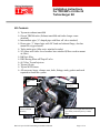
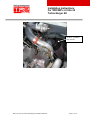
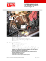
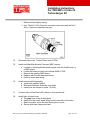
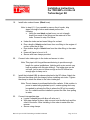
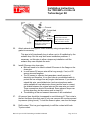
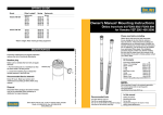
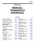
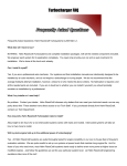
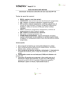
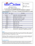
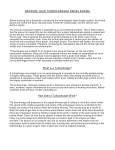
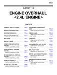
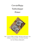
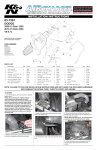
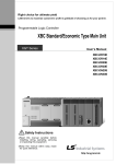
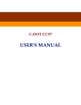
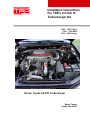
Installation Instructions
For TRD’s 2.2-liter I4
Turbocharger Kit
1990 – 1997 Celica
1990 – 1996 MR2
1990 – 2000 Camry
Burien Toyota 5S-FTE Turbocharger
Burien Toyota
Seattle, WA 98148
Installation Instructions
For TRD/NW’s 2.2-liter I4
Turbocharger Kit
Revised January 13, 2004
Burien Toyota 5S-FTE Turbocharger Installation Manual
Page 2 of 30
Installation Instructions
For TRD/NW’s 2.2-liter I4
Turbocharger Kit
Burien Toyota 5S-FE Turbo Installation Instructions
Disclaimer: This project and related modifications are the responsibility of the
vehicle owner. Alterations may be required to the engine to allow the installation
of a turbo charger. Neither Toyota Motor Sales, U.S.A., Inc. nor Burien Toyota
can be held responsible for changes required to install this kit. Although, rest
assured we will provide support before, during and after the installation and make
every attempt to work with you to make your installation a successful one.
Be sure to read and understand these entire instructions before starting your
installation to be sure you have all parts and tools needed to complete the work.
Also inspect your engine before installing this kit to be aware of leaks, vacuum or
fluid, loose parts or damaged parts. Be sure your engine is running well before
the installation.
For technical questions or comments contact:
Burien Toyota
15025 1st Ave. South
Seattle, WA 98148
800-654-6456
[email protected]
Don Voeller or Ray Meek
M-F 7:30AM - 6:00PM PST
Turbocharger Kit Part Number: 00602-17620-201
Burien Toyota 5S-FTE Turbocharger Installation Manual
Page 3 of 30
Installation Instructions
For TRD/NW’s 2.2-liter I4
Turbocharger Kit
The following parts are not required, but you may want to have on hand:
Fresh Toyota engine coolant
New engine oil (preferably synthetic) and new Toyota oil filter
New parts to perform a tune-up (spark plugs, distributor cap & rotor). If
you do replace your plugs, you may want to use a colder plug to reduce
the chance of detonation.
New Ignition wires, if your current wires are old
New Toyota fuel filter (since you’re replacing the expensive injectors)
Shorter oil filter union from Toyota (See step #11)
Tie-wraps to secure vacuum lines (See step #27)
Shielded audio cable (See step #26.b)
For automatic transmissions, consider replacing the transmission fluid with
a good synthetic brand and installing an ATF cooler.
Burien Toyota 5S-FTE Turbocharger Installation Manual
Page 4 of 30
Installation Instructions
For TRD/NW’s 2.2-liter I4
Turbocharger Kit
Kit Contents
Toyomoto exhaust manifold
Garrett TB0344 turbo (Exhaust manifold and turbo charger come
attached)
Intermediate pipe (‘S’ shaped pipe with blow off valve attached)
Down pipe (‘J’ shaped pipe with 90° bend and exhaust flange, also has
mount for oxygen sensor)
Turbo intake pipe (May arrive attached to turbo)
90º elbow with valve cover breather hose attached (Elbow used to mount
air filter)
K&N air filter
HKS Racing Blow-off/Pop-off valve
(4) 360cc Toyota Injectors
Toyota Oil pan
Toyota MAP Sensor
All necessary hoses, clamps, nuts, bolts, fittings, studs, gaskets and such
required to install the system.
Intermediate
pipe
HKS blow
off valve
Turbo charger/
exhaust manifold
assembly
Down pipe (cut to length and with custom
pipe already welded in place by exhaust
shop)
Oxygen sensor
mount
Burien Toyota 5S-FTE Turbocharger Installation Manual
Page 5 of 30
Installation Instructions
For TRD/NW’s 2.2-liter I4
Turbocharger Kit
90º elbow, with K&N
filter attached
Burien Toyota 5S-FTE Turbocharger Installation Manual
Page 6 of 30
Installation Instructions
For TRD/NW’s 2.2-liter I4
Turbocharger Kit
MAP sensor
Intermediate pipe
Exhaust gas
temperature
probe (Not
included in kit)
Turbo intake
pipe
Burien Toyota 5S-FTE Turbocharger Installation Manual
Page 7 of 30
Installation Instructions
For TRD/NW’s 2.2-liter I4
Turbocharger Kit
Preparation for Removal of Stock Components
•
Before you begin, TRD recommends that you thoroughly clean the engine and engine
compartment. If you don’t, grease buildup on parts could become dislodged during the procedure
and fall into the engine.
• Make sure the engine has cooled fully before you begin.
• To help you later, we suggest you draw diagrams of your engine’s cable routing before you
disconnect anything. You can do the same for the vacuum hoses; however, some of the vacuum
connections on your stock manifold may not be the same as those on the turbocharger.
•
The TRD turbocharger kit has been designed to reuse most of the stock nuts and bolts.
Therefore, as you remove them, keep them with their components or label them for location. This
will assure a faster, easier installation.
Installation instructions:
1.
Identify each part listed in the parts list. Dry fit pieces to understand how
they go together. Be sure all required parts (clamps, hoses, etc.) are
included before starting.
2.
Inspect engine for leaks, specifically oil and coolant. If any leaks are
found, try to fix these before performing the installation.
3.
Disconnect negative terminal from battery.
4.
Drain coolant.
5.
Drain engine oil. Keep drain plug handy for reuse later in step 10.a.
6.
Remove air cleaner box.
a. Remove air temp sensor from air cleaner box.
b. Secure temp sensor to any convenient spot using wire tie.
c. It just has to read ambient air temperature.
Burien Toyota 5S-FTE Turbocharger Installation Manual
Page 8 of 30
Installation Instructions
For TRD/NW’s 2.2-liter I4
Turbocharger Kit
7.
Remove exhaust manifold assembly.
a. Remove the six bolts and manifold upper heat insulator.
b. Remove O2 sensor.
c. Remove the two bolts, two nuts and three way catalytic stay.
d. Remove the six nuts, the exhaust manifold and catalytic converter
assembly.
Burien Toyota 5S-FTE Turbocharger Installation Manual
Page 9 of 30
Installation Instructions
For TRD/NW’s 2.2-liter I4
Turbocharger Kit
8.
Install turbo oil feed.
a. On the drivers side, front of the cylinder head is the oil pressure
sensor.
b. Remove the oil pressure sensor.
c. Install the oil pressure tee, in place of the oil pressure sensor.
d. Install the oil pressure sensor into the straight side of the oil
pressure tee. Be sure to use a high temperature sealant such as
RTV to seal the threads on the tee and oil pressure sensor.
e. Test fit the intermediate pipe with the tee in place. Also, be sure
the oxygen sensor connectors will fit before fully tightening the tee.
f. Reconnect the oil pressure sensor wire.
Burien Toyota 5S-FTE Turbocharger Installation Manual
Page 10 of 30
Installation Instructions
For TRD/NW’s 2.2-liter I4
Turbocharger Kit
Oil supply
line tee
Oil pressure
switch
9.
Remove old oil pan.
Note: The pan may be very difficult to remove since it was
attached using the Form In Place Gasket (FIPG) material.
It may be necessary, using a long flat head screwdriver
and hammer, to try to separate the pan from the block
from up above. From within the engine compartment,
locate a spot where the screwdriver can be placed against
the oil pan and tap with hammer to separate the two. Or
the use of an SST, as illustrated below, can be used to
separate the oil pan.
Burien Toyota 5S-FTE Turbocharger Installation Manual
Page 11 of 30
Installation Instructions
For TRD/NW’s 2.2-liter I4
Turbocharger Kit
10.
Install new oil pan using the cork gasket provided instead of FIPG.
a. Use oil drain plug from old pan.
11.
Remove one (1) engine oil coolant hose.
a. Located under the oil filter is an engine oil cooler. This cooler has 2
hoses connected to it coming from a water rail located on the front
of the block.
b. Remove one of the two hose; later we will be connecting turbo
coolant hoses to these fittings.
Note: At this point you should test-fit the turbo assembly to be
sure the turbo turbine housing is not interfering with
access to the oil filter and the oil dipstick. If it is, removal
of the oil cooler will be necessary. Also, if the dipstick
does not clear the turbo, bending the tube to reorient the
dipstick will be necessary. This is best left to the exhaust
shop since a torch will be required to properly bend the
tube without kinking it.
If the oil cooler does need to be removed to provide the
clearance, the following steps will replace step #11 above:
i. Remove the small nut holding the oil cooler to the
engine block.
ii. Remove the tube the oil filter is mounted to (also
called a union or relief valve).
iii. Order the Toyota part 90404-19002 to replace the
original union or relief valve. These are readily
available from many Toyota dealers since people
Burien Toyota 5S-FTE Turbocharger Installation Manual
Page 12 of 30
Installation Instructions
For TRD/NW’s 2.2-liter I4
Turbocharger Kit
often cross-thread their oil filters during oil changes.
They are also inexpensive (less than $10USD)
iv. Install this piece in place of the original union and
tighten properly.
v. Later, the coolant lines originally used for the oil
cooler will be routed to the turbo.
Coolant hoses
Burien Toyota 5S-FTE Turbocharger Installation Manual
Page 13 of 30
Installation Instructions
For TRD/NW’s 2.2-liter I4
Turbocharger Kit
Oil cooler
removed
Coolant
hoses
12.
Remove valve cover.
a. Disconnect PCV hose.
b. Remove 4 spark plug wires from valve cover.
c. Remove 4 valve cover retaining nuts (30 mm socket)
d. Pull valve cover.
13.
Remove and install injectors.
a. Remove gas cap, to relieve pressure.
b. Unplug wires from all 4 injectors.
c. Unbolt fuel rail, 2 bolts
d. Hold fuel rail back and remove injectors from cylinder head.
e. Install new o-rings and grommets on injectors. Apply a light coat of
gasoline onto the new O-ring before installing onto each injector
f. Install new injectors into cylinder head.
Hint: If injectors do not rotate smoothly, the probable cause is
incorrect installation of O-rings.
g. Install fuel rail onto injectors
h. Install fuel rail bolts, torque to specs. (9 ft-lb)
Burien Toyota 5S-FTE Turbocharger Installation Manual
Page 14 of 30
Installation Instructions
For TRD/NW’s 2.2-liter I4
Turbocharger Kit
i.
Reconnect fuel injector wiring.
Hint: The No.1 & No.3 injector connectors are brown and the No.2
& No. 4 injector connectors are gray.
14.
Re-install valve cover. Torque 30mm nuts to17ft-lb.
15.
Install new Manifold Absolute Pressure (MAP) sensor.
a. Located on the firewall behind the engine, near the throttle body, is
a MAP sensor.
b. Locate the brown box with part number 89420-17030.
c. Remove the existing MAP sensor.
d. Replace with the new pressure sensor.
e. Hook up hoses and wiring.
16.
Install turbo/manifold assembly
a. Install new manifold gasket
b. Slide manifold/turbo assembly onto studs
c. Install nuts and torque to specs. (36 ft-lb)
17.
Connect turbo oil feed line to 90° elbow on oil pressure tee.
18.
Install turbo oil drain hose.
a. The gray hose is the oil drain hose
b. Attach it to the center brass fitting on the lower side of the turbo.
c. Attach the other end to the tube coming from oil pan.
d. Secure with hose clamps provided.
Burien Toyota 5S-FTE Turbocharger Installation Manual
Page 15 of 30
Installation Instructions
For TRD/NW’s 2.2-liter I4
Turbocharger Kit
19.
Install turbo coolant hoses. (Black hose)
Note: In step #11, if you needed to remove the oil cooler, skip
steps a through d below and instead perform the
following:
• Using the new black coolant hose, run cut-to-length
hoses from each of the fittings on the water rail to the
turbo. Proceed to step 19.e below.
a. Under the turbo are two brass fittings for coolant.
b. Run a length of black coolant hose from one fitting to the engine oil
cooler, under the oil filter.
c. Run another length of black hose from the other fitting to the water
rail.
d. Hoses will have to be cut to fit.
e. Secure with hose clamps provided.
20.
Connect turbo intake pipe to the turbo and secure to turbo.
Note: This pipe is left long while manufacturing to provide enough
length for various installations. Vehicles with cruise control may
have a problem with this pipe hitting it. The intake pipe can be
cut back, just be sure to leave enough so the 90º elbow has
enough pipe to clamp on to.
21.
Install the included K&N air cleaner attached to the 90º elbow. Attach the
filter and the elbow (with the clamps) before installing onto turbo. Tighten
the clamp to attach the elbow to the turbo intake pipe.
Note: The air cleaner is positioned behind the radiator. If this position is
prone to water being splashed up at it, custom-piping work may
be needed to relocate the filter to where the OE air box used to
be. Or, a shield could be installed to protect the filter from pulling
in water.
22.
Connect intermediate pipe.
a. Locate S shaped pipe with blow off valve on it.
b. With pipe clamps in place, slide one end onto throttle body and the
other to the turbo. Note: Installing in this order is easier than the
reverse.
c. Secure using clamps.
Burien Toyota 5S-FTE Turbocharger Installation Manual
Page 16 of 30
Installation Instructions
For TRD/NW’s 2.2-liter I4
Turbocharger Kit
d. If the vehicle has an automatic transmission, check for necessary
clearance for the ATF dipstick. If needed, the dipstick tube can be
bent back slightly.
23.
Hook up vacuum hoses from HKS Racing blow off valve.
a. See diagram below
b. Run vacuum hose from lower port on blow-off valve to brass
barbed fitting on turbo housing.
c. The upper port on the blow-off valve can be left open or capped.
24.
Connect valve cover breather hose to intake pipe.
a. Using 10mm braided black hose (normally comes pre-attached to
the intake pipe).
b. Run from valve cover breather port to port on intake pipe (if not
already connected).
c. This hose must be connected to the intake pipe before the
compressor side of the turbocharger. This will guarantee a constant
vacuum to prevent pressurizing the crankcase.
d. Use a vacuum cap to block port on throttle body to avoid a vacuum
leak.
Burien Toyota 5S-FTE Turbocharger Installation Manual
Page 17 of 30
Installation Instructions
For TRD/NW’s 2.2-liter I4
Turbocharger Kit
Connect hose from turbo
intake pipe to this port on
cylinder head cover.
25.
Leave this hose
connected to throttle
body and block off open
end (to avoid a vacuum
Attach exhaust down pipe to turbo assembly using nuts provided, no
gasket is necessary.
This pipe is left intentionally long to allow a cut-to-fit installation by the
exhaust shop. But this may also cause installation problems. If
necessary, cut this pipe to allow a temporary installation until the
exhaust shop can complete the work.
26.
Install O2 sensor into down pipe.
a. Bolts will need to be used to attach O2 sensor to the flange on the
down pipe.
b. In most cases O2 sensor wire will be long enough, if not, cut O2
sensor wire and lengthen.
c. The O2 sensor is a device that generates a small amount of
electricity and therefore, it is a good idea to use shielded cable to
protect the low voltage from any engine interference. If you need to
extend this wire, use shielded wire (such as microphone audio
cable available at local electronics stores) and be sure to connect
the shields between the original wire and the new wire you install.
These connections should be soldered. Some exhaust shops can
do this when they do the custom work in step #31.
d. The shielding at the end nearest the sensor is left unattached.
27.
All vacuum lines should be tie-wrapped to avoid blowing off. This is due to
the fact that these lines that used to only see vacuum will now be exposed
to pressure (during boost). To hold the hoses in place, use short tie-wraps.
28.
Refill coolant. This is a good opportunity to refill the coolant with fresh
Toyota coolant.
Burien Toyota 5S-FTE Turbocharger Installation Manual
Page 18 of 30
Installation Instructions
For TRD/NW’s 2.2-liter I4
Turbocharger Kit
29.
Refill oil. If you do not have a Toyota filter installed, replace it. You must
use a Toyota oil filter to achieve the required clearance.
30.
Reconnect battery
31.
Visit your local exhaust shop to mate the down pipe to your exhaust
system and install new catalytic converter. The question you want to ask
the exhaust shop is, “Can you build a custom pipe with a catalytic
converter to attach a turbo charger dump pipe to a stock head pipe?” If
they can do the work, they should say that they cannot give an accurate
estimate without seeing it, but it is work they have done.
Note: In some situations, the addition of the turbo charger my not allow
the addition of a new catalytic converter in the same place as the
OE. In this case, the front pipe of the exhaust system will need to
be reworked to allow room for the new catalytic converter.
Burien Toyota 5S-FTE Turbocharger Installation Manual
Page 19 of 30
Installation Instructions
For TRD/NW’s 2.2-liter I4
Turbocharger Kit
Changes in maintenance/General suggestions to consider:
Be sure to always change your oil before the recommended 3,000-mile/3
month intervals. Your oil is critical in keeping your turbo charger cool and
lubricated. If your oil fails, your turbo will also. Using synthetic oil will stand
up much better than the petroleum-based oil.
Always be aware of any leaks. Due to higher temperatures related to turbo
charging, your coolant also becomes critical. Be sure to change this with
high quality coolant before it needs to be. Remember; do not mix different
colored coolants. If you have the Toyota red, always use the same Toyota
red coolant to top it off.
Timing belts should now be changed every 40,000 to 50,000 miles. This is
due to the additional strain the engine will endure.
Running a higher-octane fuel will help reduce the chance of detonation.
The new K&N air filter included with the kit should be serviced every
50,000 miles as per manufacturer instructions. To service, use the K&N
filter cleaning kit that is available at many auto parts stores. Follow the
directions to clean and re-oil the filter. This is a serviceable filter – not a
short-life disposable filter. Do not discard the filter when it is time to
service it.
For technical questions or comments contact:
Burien Toyota
15025 1st Ave. South
Seattle, WA 98148
800-654-6456
[email protected]
Don Voeller or Ray Meek
M-F 7:30AM - 6:00PM PST
Burien Toyota 5S-FTE Turbocharger Installation Manual
Page 20 of 30
Installation Instructions
For TRD/NW’s 2.2-liter I4
Turbocharger Kit
Miscellaneous resources:
Online sites to find more information:
http://www.poweredbytoyota.com/ssfeturbo.html : Burien Toyota’s Website
http://www.meisners.net/camry : User that installed kit
http://www.knfilters.com : K&N web site
Example dynamometer runs:
Prior to turbocharger:
<< Insert dyno run after turbo >>
Burien Toyota 5S-FTE Turbocharger Installation Manual
Page 21 of 30
Installation Instructions
For TRD/NW’s 2.2-liter I4
Turbocharger Kit
Extra information:
1. To connect an exhaust gas temperature (EGT) gauge, there is a plate on the
Toyomoto exhaust manifold that can be used to provide a mounting location for the
probe. This plate can be removed, drilled and tapped to provide a threaded fitting for
the EGT probe.
EGT probe
inserted into
exhaust
manifold
Burien Toyota 5S-FTE Turbocharger Installation Manual
Page 22 of 30
Installation Instructions
For TRD/NW’s 2.2-liter I4
Turbocharger Kit
2. A good place to connect a vacuum/boost gauge is the brake booster vacuum line.
Using a ¼” vacuum tee, the brake booster can be cut into and provide a source of
manifold vacuum & pressure. But be sure to position the tee before the check valve
used in the booster’s line. See following picture:
Old location of
check valve; new
¼” tee installed
Check valve
Brake
Booster
New vacuum/
pressure line for
gauge
Burien Toyota 5S-FTE Turbocharger Installation Manual
Page 23 of 30
Installation Instructions
For TRD/NW’s 2.2-liter I4
Turbocharger Kit
ILLUSTRATED PARTS LIST-T03/T04B
SERIES TURBOCHARGERS
IPL TURBONETICS
NO.
*28
*28
P/N
20256-2
20256-4
GARRETT
DESCRIPTION
QTY.
PRICE
REQ.
EA
405919-0002
Shaft Bearing (Std.OD.010ID)
2
5.58
405919-0004
Shaft Bearing (.010 OD-.010
ID)
2
5.58
P/N
Burien Toyota 5S-FTE Turbocharger Installation Manual
Page 24 of 30
Installation Instructions
For TRD/NW’s 2.2-liter I4
Turbocharger Kit
*28
20256-6
405919-0006
Shaft Bearing (.010 OD-Std
ID)
2
*29
30236
400624-0000
Thrust Pin
2
.25
*30
20275
407516-0004
Thrust Spacer - Carbon Seal
1
7.29
*31
30209
409695-0000
Carbon Seal
1
15.39
32
20327
430027-0025
Bearing Housing - Dry
1
85.29
32
20234
430027-0047
Bearing Housing - Wet
1
85.29
*NI
20314
406765-0002
Thrust Spring - Backplate
1
.77
5.58
Dynamic Seal Components - Not Illustrated
*NI
20320
408045-0034
Backplate - Dynamic
1
40.12
*NI
20243
406906-0000
Thrust Collar - Dynamic
1
31.24
*NI
30239
403818-0009
Piston Ring - Dynamic
1
4.37
*TO4B Component Parts Common To T3 Series Turbochargers
T3 Component Parts - Not Shown
5
20208
400724-0810
Bolt - Compressor Hsg. Metric
6
.64
7
20198
410218-0001
Clamp - Compressor Hsg.
3
.48
9
20206
400677-0816
Bolt - Turbine Hsg. Metric
6
.46
13
20236
409248-0000
Gasket - Compressor Hsg.
1
.59
13
30243
403069-0060
O-ring - Compressor Hsg.
1
2.13
18
30264-72
409639-0000
Wheel Shroud - Std Wheel
1
3.76
18
30264-03
409627-0000
Wheel Shroud - Stage II & III
1
3.76
19
30237
400764-0616
Locking Flang Bolt - Bearing Hsg.
4
.22
21
20270
430108-0003
Backplate - Carbon Seal
1
40.12
21
20317
409629-0001
Backplate - Dynamic
1
29.01
NI
10419
N/A
Carbon Seal Kit - Late Style
1
11.92
IPL
TURBONETICS
GARRETT
DESCRIPTION
QTY.
PRICE
NO.
P/N
P/N
REQ.
EA.
5
20209
400450-0001
Bolt - Compressor Hsg.
6
.45
5
20207
N/A
Locking Flange Bolt-Comp Hsg.
6
.64
6
30246
407876-0000
Lockplate - Comp. Hsg.
3
.46
7
20193
407875-0000
Clamp - Comp. Hsg.
3
.54
8
See Table
Page 12
Compressor Housing
1
9
20209
400450-0001
Bolt - Turbine Hsg.
6
.45
*10
30247
406909-0000
Lockplate- Turbine Hsg
3
.48
*11
20194
406908-0002
Clamp - Turbine Hsg. (2 bolt)
3
.95
*11
20195
408848-0002
Clamp - Turbine Hsg. (3 bolt)
2
1.15
12
See Table
Page 14 & 15
Turbine Housing
1
13
30229
403069-0064
O-ring - Compressor Hsg.
1
5.29
*14
30233
400768-0011
Locknut - Compressor
1
2.61
15
See Table
Page 12
Compressor Wheel
1
*16
30234
403818-0034
Piston Ring - Turbine End
1
17
See Table
Page 14
Turbine Wheel / Shaft
1
18
20297
407565-0000
Wheel Shroud
1
19.28
19
30248
400805-0202
Bolt - Bearing Hsg.
4
.15
Burien Toyota 5S-FTE Turbocharger Installation Manual
5.06
Page 25 of 30
Installation Instructions
For TRD/NW’s 2.2-liter I4
Turbocharger Kit
19
30226
N/A
Locking Flange Bolt - Bearing Hsg.
4
20
30249
407684-0000
Lockplate - Bearing Hsg.
2
.18
21
20196
408206-0002
Backplate Ass'y - Carbon Seal
1
40.12
*22
20304
400424-0000
Ring Seal - Backplate
1
.94
*25
20219
407634-0000
Thrust Bearing - Bronze (3 hole)
1
15.64
*25
20219-S
448110-0001
Thrust Bearing - Steel (3 hole)
1
15.64
*26
20262
409558-0000
Thrust Collar - Carbon Seal
1
14.63
*27
30235
400568-0000
Retaining Ring
4
.25
*28
20256-0
408056-0000
Shaft Bearing (Std.OD-Std.ID)
2
5.04
Burien Toyota 5S-FTE Turbocharger Installation Manual
.22
Page 26 of 30
Installation Instructions
For TRD/NW’s 2.2-liter I4
Turbocharger Kit
Garrett/AiResearch TB03-44 Compressor Map
Burien Toyota 5S-FTE Turbocharger Installation Manual
Page 27 of 30
Installation Instructions
For TRD/NW’s 2.2-liter I4
Turbocharger Kit
Symptom
Possible Causes
Corrective Action
Idles rough, “pings”
(Trouble Code PO171—Lean Code)
Lean condition—
vacuum leak
Check vacuum line connections for leaks and cracked ends.
Review factory service manual for proper factory vacuum
routing.
Review instructions for proper vacuum line routing.
Check installation of the TRD throttle body gasket. If gasket
is installed improperly, a vacuum leak will occur.
Recheck torque on throttle body bolts.
Leak at manifold gasket.
Recheck torque on intake manifold bolts.
Pings during acceleration
Low octane fuel
Fill tank with premium fuel. BE SURE TO USE 92
OCTANE FUEL.
Computer has yet to
adjust to turbocharger
Drive several hundred miles in different driving modes (Not
all steady-state highway cruising, for example).
Insufficient fuel delivery
Fuel filter old—replace. Follow factory diagnosis and
replacement procedures.
Fuel pressure low. Follow factory diagnosis and replacement
procedures.
Injector(s) clogged. Follow factory repair/replacement
procedures.
Low boost
Makes a moderately loud noise
under full throttle—intake noise
Air filter dirty
Check/replace air filter. A dirty filter restricts the air intake.
TRD dyno tests have shown that the TRD air filter is among
the best on the market for flow and filtering characteristics.
Throttle not fully opened
Recheck and adjust the throttle cable and transmission cable.
Be sure that full depression on the gas pedal achieves full
throttle opening at the throttle body.
Normal turbocharger
sound
No remedy. Turbochargers are an air pump and the pumping
action is impossible without some noise. Call TRD for
further diagnosis.
Burien Toyota 5S-FTE Turbocharger Installation Manual
Page 28 of 30
TRD/NorthWest – Burien Toyota
15025 1st Avenue South • Burien, WA 98148 • www.poweredbytoyota.com • 866.404.3333
Installation Instructions
For TRD/NW’s 2.2-liter I4
Turbocharger Kit
©2000 TRD U.S.A., Inc. Printed in USA
00602-05100-221
Burien Toyota 5S-FTE Turbocharger Installation Manual
Page 30 of 30