1
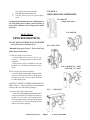
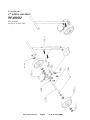
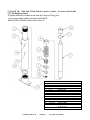
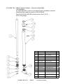
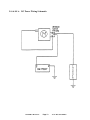
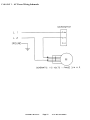
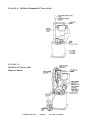
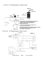
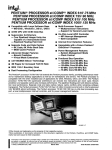
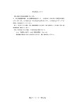
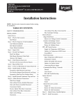
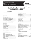
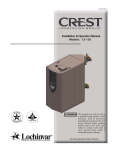
AC & DC Stackers (B, D, E, and PS Series) Installation,Operation & Service Manual Model Number ___________________ Serial # _________________________ Date placed in service _____________ IMPORTANT: READ CAREFULLY BEFORE INSTALLING OR OPERATING LIFT Part orders are subject to a $50 minimum charge January 2012 The Presto Five Year Warranty Presto Lifts, Inc. warrants all of its products against defects in the welded structural frame and, if applicable, scissor legs from faulty material and workmanship for a period of five years from the date of invoice. To read more about the warranty on this equipment, please turn to the back inside cover of this owner’s manual. This manual was current at the time of printing. To obtain the latest, most updated version, please contact the Customer Service Department or go to our website: www.PrestoLifts.com -- you will find a complete list of current owner’s manuals to print. OWNER’S MANUAL Page 2 AC & DC STACKERS CONTENTS S E C T I O N 1: Introduction..............................................................................................................4 S E C T I O N 2: Safety.......................................................................................................................4 S E C T I O N 3: Installation................................................................................................................4 S E C T I O N 4: Operation..................................................................................................................5 A. Operating Instructions B. Daily Operations Maintenance Checks S E C T I O N 5: Maintenance.............................................................................................................5 A. Instructions B. Monthly Operations Maintenance Checks S E C T I O N 6: Troubleshooting.......................................................................................................6 RESTOCKING POLICY & RGA POLICY......................................................................26 RETURN MATERIALS AUTHORIZATION (RMA) PROCEDURES...........................27 WARRANTY............................................................................................... BACK COVER LIST OF FIGURES: Chain Roller Assemblies (Figure 1) ................................................................................................................ 7 5th Wheel Assembly (Figure 2A, 2B & 2C) ................................................................................................ 8-9 1,000 lb. Capacity Cylinder Breakdown (Figure 3A) previous to March 2000........................................... 10 2,000 lb. Capacity Cylinder Breakdown (Figure 3B) previous to March 2000.............................................11 2,000 lb. Capacity Cylinder Breakdown (Figure 3C) ................................................................................... 12 DC Power Wiring Schematic - Standard (Figure 4) ..................................................................................... 13 Standard DC Power Pack Illustration (Figure 5) .......................................................................................... 14 DC Power Pack w/ Remote Control Illustration (Figure 6) .......................................................................... 14 AC Power Wiring Schematic - Standard (Figure 7) ..................................................................................... 15 Old Style Standard AC Power Pack Illustration (Figure 8) .......................................................................... 16 Old Style AC Power Pack w/ Remote Control Illustration (Figure 9) .......................................................... 16 DC Wiring Schematic w/ Remote Control (Figure 10) ................................................................................ 17 AC Wiring Schematic w/ Remote Control (Figure 11A) .............................................................................. 17 New Style DC Power Pack (Figure 11B & 11C)...................................................................................... 18-19 Generic Floor Lock Assembly (Figure 12) ................................................................................................... 20 Bearing Bracket Assembly (Figure 13) ......................................................................................................... 20 Pallet Straddle Stacker Illustration - Front View(Figure 14) ........................................................................ 21 Pallet Straddle Stacker Illustration - Back View (Figure 15) ........................................................................ 22 Standard Replacement Component Listing ............................................................................................. 23-24 Hydraulic Oil Specifications (Table 1).......................................................................................................... 25 OWNER’S MANUAL Page 3 AC & DC STACKERS SECTION 1 • All personnel must stand clear of the lift while in INTRODUCTION This manual attempts to provide all of the information necessary for the safe and proper installation, operation and maintenance of Presto Lifts Battery Operated and Electric Stackers. It is important that all personnel involved with the installation, maintenance or operation of the stacker read this manual. Additional manuals are available upon request or at www.prestolifts.com. Each of the Presto Lift stackers is equipped with nameplate, serial number and model identifications. Please refer to these numbers when ordering parts or requesting further information. The Presto Lifts stackers are designed for lifting, lowering and positioning a wide variety of loads. WHERE UNIQUE SITUATIONS ARISE, WHICH ARE NOT COVERED IN THIS MANUAL, CALL PRESTO LIFTS FOR FURTHER INSTRUCTIONS. The battery-operated stackers are designed for in-plant/ nonhazardous locations only. These units are not for personnel lifting. All equipment is manually propelled and powered vertical travel. SECTION 3 INSTALLATION A. INSPECTION: Upon receipt of the stacker, inspect the equipment completely to determine if there is any shipping damage, and that the lift is complete. Presto Lifts tests and inspects every piece of equipment prior to shipment. If damage is apparent, a freight claim must be filed with the freight company. Do not use the lift if there appears to be any damage. With the lift in a collapsed position, check the following: • Check for signs of damage especially to the back SECTION 2 SAFETY The battery-operated stackers are very powerful lifts capable of doing large amounts of work. DO NOT INSTALL OR OPERATE THESE LIFTS WITHOUT CAREFULLY READING THIS MANUAL. In order to provide for the safe operation of these stackers, Presto Lifts has identified certain hazards that may occur during the installation, maintenance and use of these lifts. For safety reasons these units are designed to be serviced or repaired in the collapsed position. If performed properly, this will greatly reduce the possibility of injury. WARNING! • Do not perform any repair work on lifts if there is a load on the forks or platform. • Do not perform any repair work if the forks or platform is in the raised position. OWNER’S MANUAL motion. • Do not put hands or feet under the forks or platform. • Do not stand underneath the forks or platform. • Do not stand in front of the stacker while in motion. • Do not stand, sit or climb on the lift. • Do not use the lift on soft, uneven or unstable surfaces. • Do not exceed the load center or capacity. Page 4 cabinet that houses the battery, electrical/hydraulic power pack. • Check all connections for tightness. Is there hydraulic fluid visible? • Check base frame for dimensions and structural integrity. • Inspect for any bent or damaged metal parts. B: REMOVING FROM PALLET Each of the Presto stackers is shipped out on a pallet or skid. Prior to removing the unit from the pallet or skid, remove all tie down straps and packaging. Visually inspect the unit as closely as possible. With an overhead hoist or forklift, carefully pick up the lift taking into consideration the center of gravity of the unit. If you choose to pick the unit with an overhead hoist, use a nylon sling and hoist with a minimum of 2,000-lb. capacity. The nylon sling will not do any damage to the steel construction of stacker. Pick the unit up AC & DC STACKERS by the top cross member of the lift. Be careful of the stacker swinging once fully lifted off the pallet or skid. Have all personnel completely cleared from the area. Pick the unit up approximately six inches above the pallet or skid. Once raised, remove the pallet or skid from below the lift. Do not move the lift around in the air once secured in the raised position, remove the pallet from below and place the stacker on the ground. 1. Battery (If Equipped) A. Check for corroded and loose terminals. A white powder substance will be present if there is any existing corrosion. B. Visually inspect for any cracks or damage to the casing. C. Check for loose battery tie-downs. 2. Charger (If Equipped) A. Inspect wire connections. B. Check power cord for nicks/damage. C. Check charger for proper mounting. SECTION 4 OPERATION Hydraulic System D.Inspect pump and cylinder for oil leaks. E. Check hydraulic oil level. F. Check hydraulic fittings and hoses. G. Check ram for nicks/damage. H. Check fluid level. Unscrew plug or cap on reservoir with the forks or platform in the lowered position. The fluid will be 1/2 to 3/4 of an inch from the opening. A. OPERATING INSTRUCTIONS: 1. 2. 3. To raise lift, push control handle. To lower lift, pull control handle. Whenever the control handle is released, the lift stops. AUTHORIZED OPERATORS SHOULD READ AND UNDERSTAND ALL INSTRUCTIONS, PRECAUTIONS AND WARNINGS. IMPROPER USE OF THIS LIFT TRUCK COULD RESULT IN INJURY AND/OR DAMAGE TO LOAD AND EQUIPMENT. • Inspect the lift for damaged or worn parts. • Do not use if not in safe operating condition. • Use lift on hard level surfaces only. • Make sure load is evenly distributed, not loose or unstable, and is as far back on platform or forks as possible. Do not pick up loads on tips or forks or edge of platform. •For fork models, adjust forks to the maximum practical width. Pick up loads on both forks. •Do not overload. Check load center and load weight capacities on manufacturer’s nameplate. •Make sure travel and work area is clear of obstructions. •Check overhead clearance before lifting loads or transporting. •Make sure floor lock pad is in firm contact with floor before lifting load, lowering load or using as a workstation. •)Brace or block lift when sliding loads on or off platform or forks. B. DAILY OPERATIONS MAINTENANCE CHECKS: OWNER’S MANUAL 3. Frame Assembly A. B. C. D. Check floor lock. Check placement of safety screen. Check chain roller assembly connections. Check for any worn or damaged parts. SECTION 5 BATTERY MAINTENANCE A. PREPARING TO CHARGE A BATTERY 1. Always turn off E-stop and key switch before working with the batteries. 2. Be sure the area around the stacker and the battery is well ventilated while battery is being charged. 3. The battery terminals, connections and wiring connections should be clean and free of corrosion. When cleaning any of these components wear a face shield or other suitable protective eyewear. 4. For a sealed battery (a battery without cell caps) carefully follow the manufacturer’s recharging instructions that are provided with the battery. If Page 5 AC & DC STACKERS you do not have a copy of these instructions or the instructions for the battery charger they are available free of charge by calling Presto @ 1-800-3439322. SECTION 6 MAINTENANCE 1. Locate charger as far away from battery as the cables permit. 2. Do not operate charger in a closed area or restrict ventilation in any way. Operation of Presto Hydraulic Lifts is very simple — as is their construction and require very little maintenance. Reasonable care will result in excellent trouble-free performance. Presto Hydraulic Lifts are designed for one-man operation and ease of performance. A. INSTRUCTIONS: ⇑ Grease wheels and casters at least once a month to maintain easy roll of lift. ⇑ Use only Hydraulic Oil (Conoco Super Hydraulic 32) in the hydraulic system. See hydraulic oil specifications table on page 25. ⇑ Do not overload your lift. C. PRECAUTIONS FOR GROUNDING AND AC POWER CORD CONNECTION B. MONTHLY OPERATIONS MAINTENANCE CHECKS: 5. Read, understand and follow all battery and batterycharger manufacturer’s specific precautions while working with and/or charging batteries. B. LOCATING THE CHARGER Charger should be grounded to reduce risk of electric shock. Charger is equipped with an electric cord having an equipment-grounding conductor and grounding plug. The plug must be plugged into an outlet that is properly installed and grounded in accordance with all local codes and ordinances. DANGER Never alter the AC cord or plug provided. If it will not fit outlet, have proper outlet installed by a qualified electrician. Improper connection can result in a risk of an electric shock. D. BATTERY CHARGER CONNECTION PRECAUTIONS CAUTION Connect and disconnect the DC output plug (or clips) only when the AC cord is disconnected from the electric outlet. Never allow clips to touch each other. 1. To charge the unit, plug the charger into the 110 volt wall outlet. The charger is pre-wired to the battery. 2. Disconnect the charger from the 110 volt wall outlet once the indicators read fully charged. 1.Battery A. Clean terminals. B. Clean battery compartment area. C. Check specific gravity — fully charged battery should read 1265. Using a hydrometer that measures specific gravity can check this. 2. Hydraulic System A. Clean and inspect hydraulic cylinder. B. Lubricate chain with a rust inhibitive lubricant. C. Check chain tension. The chain should be tight enough so that it does not come off of the roller assembly. 3. Frame Assembly A. Clean and lubricate all roller bearings and cam followers. B. Clean and inspect all welds. C. Check wheels for wear and damage. D. Inspect nameplate for legibility. Place the serial and model number shown on the nameplate on the cover of the manual for future reference. 4. Adjust Straddle Stacker Legs A. Secure the stacker with an overhead crane or fork truck allowing the weight to be removed from the stacker legs. B. Loosen the adjustment bolts and adjust both OWNER’S MANUAL Page 6 AC & DC STACKERS legs equally to the desired width. C. Re-tighten the adjustment bolts. D. Test the stacker to ensure proper adjustment. F i g u r e 1: Chain Roller Assemblies P/N: 0584-VR (single chain roller) All adjustments should be done by qualified personnel. If in doubt, please contact your local dealer or Presto Lifts Customer Service Department at 800343-9322. P/N: 0585-VR SECTION 7 TROUBLESHOOTING IF LIFT DOES NOT RISE TO FULL HEIGHT — check for leaks or shortage of oil. P/N: C105A-TVR Maintain the proper oil level. To check oil level, follow these instructions: A.) Old style Power Unit (vertical) • On left hand side, on top of oil well, you will find a hexagon cap screw which is also a dipstick. • Remove the cap screw and fill oil well with hydraulic oil. Oil should reach notch on dipstick. P/N: C105-BVR 62'' 2700# C105-CVR 74'' 2700# B.) New style Power Unit (horizontal) • Unscrew the fill plug located on the top of the reservoir. The oil level will be 1-2 inches down from the top. If the oil level is down, fluid can be added at this point. IF THE LIFT TENDS TO CREEP DOWNWARD UNDER A LOAD — a speck of dirt may be obstructing the seating of the valve and allowing leakage. To correct, follow these instructions: • Raise lift to full lifting height and then lower it to lowest point of lift. It may be necessary to do this five or six times. In lowering the lift, lower it in stages, that is, lower the lift six inches to a foot at a time. This will dislodge the dirt and lift will operate properly. OWNER’S MANUAL P/N:C105-B-TVR Page 7 AC & DC STACKERS F i g u r e 2a: 5th Wheel Assembly Breakdown P/N: 1003-016VR This assembly used prior to June 2003 OWNER’S MANUAL Page 8 AC & DC STACKERS F i g u r e 2b: 5th Wheel Assembly P/N: 80000624VR Old single wheel 5th wheel assembly replacement wheel is obsolete. To convert to a new 5th weel assembly, one adapter trunnion, P/N 1003-014-02 is required. 7 BK-HA WASHER LCK-SPT STL .37 6 BK-HA SCREW HHCS .37-16 X 1.00 5 BK-HA NUT HEX STL .50-13 4 BK-HA WSHR LCK-SPT STL .5 3 HA SCREW HHCS .50-13 X 1.50 2 ACP TRUNNION WM 5TH WHEEL 1 ACP 5TH WHEEL ASSEMBLY ItemDescription 4 4 4 4 4 1 1 Qty N0260 N0920 N0160 N0280 N1050 80000966VR 1003-016VR P/N 2 2 FW06 N1265 6 2 1 2 1 1 Qty 30001085 10029103 30001083 30001082 1003-013 80000693 P/N F i g u r e 2c: 5th Wheel Assembly P/N: 1003-016VR Used from June 3, 2004 on. 9 SPRING 8 ROLL PIN 7 6 WASHER 5 SPACER 4 PIN 3 WHEEL 2 CASTER ASSEMBLY 1 5TH WHEEL HANDLE ItemDescription OWNER’S MANUAL Page 9 AC & DC STACKERS F i g u r e 3A: 1000, 1500, 2700 & 3000 lb. Capacity Cylinder - Previous to March 2000 (78'' Lift Height or Less) If cylinder barrel #3 connects to the base #13 with an O-Ring joint (only a seam will be visible) use seal kit H100KVR. Seal kit P/N H100KVR includes items 4 thru 12. ItemP/N 1 H108-XXX 2 H106-XXX 3 H101-XXX 4 H108A 5 H109 6 H111 7 H112 8 H113-2000 9 N0130 10 H107A 11 H104-1000 12 H105-1000 13 H107-1000-1 14 H102-2000 15 N1210 OWNER’S MANUAL Page 10 Description CYLINDER RAM 1000# INNER CYLINDER OUTER CYLINDER BEARING CHEVRON SUPPORT CHEVRON SET SPRING CHEVRON RAM GUIDE WASHER RAM GUIDE NUT RAM GUIDE O'RING CYL. BASE O'RING RAM SEAL CAP CYLINDER BASE CYLINDER 1/4" NPT-1/4" Push 90 Elbow-Poly Flo 1/4" NPT Plug AC & DC STACKERS Qy. 1 1 1 1 1 1 1 1 1 1 1 1 1 1 1 F i g u r e 3B: 2000 lb. Capacity Cylinder -- Previous to March 2000 (All lift heights) If cylinder barrel #2 connects to the base #3 with a threaded connection (threads will be visible) use seal kit H100-2000KVR. Seal kit P/N H100-2000KVR includes items 4 thru 12 & 15. XXX = lifting height OWNER’S MANUAL Page 11 Item 1 2 3 4 5 6 7 8 9 10 11 12 13 P/N H108-XXX H106-XXX H107-2000 H108A-2000 H109-2000 H111-2000 H112-2000 H113-2000 N0130 H104-2000 H105-2000 H105-2000A H102-2000 14 15 M411 H107-2000A Description Cylinder Ram 2000# Inner Cylinder Base Cylinder Bearing Chevron Support Chevron Set Chevron Spring Ram Guide Washer Ram Guide Nut Ram Guide O-Ring Upper Cap Cylinder Cap O-Ring Lower Cap Fitting - 1/8" NPT-1/4" Push 90 elbow-poly F10 Set Screw O-Ring, Cylinder Base AC & DC STACKERS Qty 1 1 1 1 1 1 1 1 1 1 1 1 1 2 1 F i g u r e 3C: 2,000 lb. Capacity Cylinder - April 2000 to present (all AC lifts and all 2 piston hand pump lifts) WELDED * Items are in seal kit 80000867 11 LOCKING WIRE 1 10 O-RING 1* 9 O-RING 1 * 8 GLAND 1 7 TUBE WELDMENT 1 6 3/4 - 16 HEX NUT 1 5 WEAR RING 1 * 4 PISTON SEAL 1 * 3 PISTON 1 2 O-RING 1 * 1 SHAFT 1 ITEMDESCRIPTION QUANTITY OWNER’S MANUAL Page 12 AC & DC STACKERS F i g u r e 4: DC Power Wiring Schematic OWNER’S MANUAL Page 13 AC & DC STACKERS F i g u r e 5: Old Style DC Power Pack Old Style DC Power w/ Remote Control F i g u r e 6: OWNER’S MANUAL Page 14 AC & DC STACKERS F i g u r e 7: AC Power Wiring Schematic OWNER’S MANUAL Page 15 AC & DC STACKERS F i g u r e 8: Old Style Standard AC Power Pack F i g u r e 9: Old Style AC Power with Remote Control OWNER’S MANUAL Page 16 AC & DC STACKERS F i g u r e 10: F i g u r e 11A: DC Wiring Schematic w/ Remote Control AC Wiring Schematic w/ Remote Control OWNER’S MANUAL Page 17 AC & DC STACKERS F i g u r e 11B: New Style DC Power Pack for stackers Call the Presto Parts department to determine available parts for the new style power unit. Have the model and serial number of the lift available. OWNER’S MANUAL Page 18 AC & DC STACKERS F i g u r e 11C: OWNER’S MANUAL Page 19 AC & DC STACKERS F i g u r e 1 2: Item No. Generic Floor Lock Assembly Floor Lock Assembly Detail Description 1 PSL23 – Lock Assy. Bracket 2 PSL29 – Collar, Shaft 3 0491-XX – Handle, Lock 4 PSL25 – Lever, Lock 5 PSL28 – Pin, Lock Lever 6 N0810 – Bolt, Handle Lock 7 N0040 – Nut, Handle Lock 8 M437 – Pad, Lock 9 PSL21ABC – Holder, Lock Pad 10 PSL26 – Spring, Lock Return 11 PSL24 – Mount, Lock 12 PSL22 – Stud, Adjustable 13 2340772 – Nut, Adjustable NOTE: Model and Serial Number Required When Ordering Parts F i g u r e 1 3: Bearing Bracket AssemblyFor B, EPF, & ESF models only. For all other models, contact Parts Department. Bracket Assembly Detail Item No. Description 1 Bracket – Left (C111VR) 2 Bracket – Right (C112VR) 3 Hood Bearing (C107) 4 Hood Bearing, Nut (2340772) 5 Lock Washer (N0300) 6 Internal Lock Washer (N0427) 7 Spacer (C108) 8 Bearing Plate Bolt (N0920) 9 Plate Lock Washer (N0261) 10 Side Thrust Bearing (C114) 11 Bolt, Side Thrust (N0961) 12 Lock Washer (N0260) OWNER’S MANUAL Page 20 AC & DC STACKERS F i g u r e 1 4: OWNER’S MANUAL Pallet Straddle Stacker Component Identification Item No. Description 1 Chain Roller Assembly 2 Adjustable Forks 3 Phenolic Wheels 4 Hydraulic Cylinder 5 Flow Control Valve 6 Floor Lock Handle 7 Bearing Bracket Assembly Page 21 AC & DC STACKERS F i g u r e 15: Pallet Straddle Stacker Component Identification Item No. Description 1 DC Power Pack 2 12 volt Battery 3 Internal Battery Charger 4 Hand Lever – Power Up 5 Floor Lock Assembly 6 5th Wheel Assembly (see page 8) 7 Rigid Phenolic Wheel 8 Swivel Wheels – Underneath OWNER’S MANUAL Page 22 AC & DC STACKERS Recommended Spare Parts Listing * = Old Style Power Units (see Figure 6, 7, 9 & 10) ** = Old Style Ciylinder kits (see Figure 3A & 3B) Description Flow Control Valve Adjustable Flow Control Valve Release Handle Release Handle Connecting Pin Release Handle Spring Release Hanlde Plastic Knob Battery Cable – Ground Battery Cable – Positive Battery Charger – 10 AMP Battery Charger – 15 AMP Oldham Coupling Switch Motor to Switch connector DC Motor – 12 volt Solenoid For DC Hand Pendant Solenoid Coil Solenoid Valve – Down DC Solenoid Valve w/ Coil – DC Down Hand Pendant for 12 volt power packs Floor Locks Floor Lock Adapters 5th Wheel Assembly – Complete OWNER’S MANUAL Part Number B211RC-A 2533004 * B243 * B243C * B244 * B245 B246 B247 Call Presto Call Presto * B255 * B256 * B257A * B258 * B262RC * 1000-056-01 * B263RC-01 * B263RC B268RC-B C100 C100AVR 1003-016VR Page 23 Used On: Model All units Optional Purchase All Units (Standard DC power) All Units All Units All Units All Units All Units All B Series, C and D Series All P Series All Units All Units All Units All 1000 & 1500 lb. capacities All Units w/ Remote Controls A115VAC, 12VDC All Units w/ Remote Controls All Units w/ Remote Controls All Units w/ Remote Controls All B5, B6, B7, E, D and C Series All B5, B6, B7, E, D and C Series All P Series and Optional B Series AC & DC STACKERS Description Swivel Caster Assembly w/4x2 steel wheel Swivel Caster Assembly w/ 4x2 rubber wheel Swivel Caster Assembly w/4x2 poly wheel Swivel Caster Assembly w/4x2 phenolic wheel Swivel Caster Assembly w/5x2 steel wheel Swivel Caster Assembly w/ 5x2 rubber wheel Swivel Caster Assembly w/5x2 poly wheel Swivel Caster Assembly w/5x2 phenolic wheel 4x2 Steel Wheel Only For Swivel Caster Assembly 4x2 Rubber Wheel Only For Swivel Caster Assembly 4x2 Poly Wheel Only For Swivel Caster Assembly 4x2 Phenolic Wheel Only For Swivel Caster Assembly 5x2 Steel Wheel Only For Swivel Caster Assembly 5x2 Phenolic Wheel Only For Swivel Caster Assembly 5x2 Rubber Wheel Only For Swivel Caster Assembly 5x2 Poly Wheel Only for Swivel Caster Assembly Wheel Shaft With Washer Cylinder Seal Kits (1,000 lb. capacity units) Cylinder Seal Kits (2,000 lb. capacity units) 4x1.5 Rubber 4x1.5 Rubber with Swivel Caster OWNER’S MANUAL Part Number Used on: Model C101S2 C101R2 C101P2 C101PH2 C101S5 C101-R5 C101P5 C101PH5 2361034 C102MR4 C101C C101D C102S (Qty 2) C102PH (Qty 2) C102R (Qty 2) C102P (Qty 2) C103 **H100KVR **H100-2000KVR C101B C101R Page 24 Optional Optional Optional Standard - Check Equipment Optional Optional Optional Standard - Check Equipment Optional Optional Optional Standard - Check Equipment Optional Optional Optional Optional All Units All 1,000 lb. capacity units All 1500, 2000 and 2700 lb. cap. AC & DC STACKERS Table 1 – Hydraulic Oil Specifications If the lift will be used at normal ambient temperatures, Presto Lifts supplies the unit with Conoco Super Hydraulic 32 oil. This may be replaced by any other good quality oil with 150 SSU at 100° F and rust and oxidation inhibitors and anti-wear properties. If the lift will be used at ambient temperatures below 0°F, use aircraft hydraulic oil. Use Type 15 aircraft hydraulic oil. The following are equivalent to Conoco Super Hydraulic 32: TYPE MANUFACTURER AW32 .......................................... CITGO DTE 24 ........................................ EXXON/MOBIL NUTO H32 .................................. EXXON/MOBIL AMOCO AW32 ............................ CHEVRON (AMOCO CO.) CAUTION! It is very important to keep the hydraulic oil free of dirt, dust, metal chips, water, and other contamination. Most of the problems with hydraulic systems are caused by contamination in the oil. Ordering Replacement Parts Presto Lifts has carefully chosen the components in your unit to be the best available for the purpose. Replacement parts should be identical to the original equipment. Presto Lifts will not be responsible for equipment failures resulting from the use of incorrect replacement parts or from unauthorized modifications to the unit. Presto Lifts can supply all replacement parts for your lift. With your order, please include the model number and the serial number of the unit. You can find these numbers on the name plate. This plate is located within the cabinet, or on the angle iron cylinder cross support. To order replacement parts, please call the Presto Parts Department. Parts are shipped subject to the following terms: • FOB factory • Returns only with the approval of our parts department. • Credit cards preferred (except parts covered by warranty). • Freight collect for truck (except parts covered by warranty). • Freight – prepaid and invoice for small parcel shipments (except parts covered by warranty). Parts replaced under warranty are on a “charge-credit” basis. We will invoice you when we ship the replacement part, then credit you when you return the worn or damaged part. Presto Parts Department 21 Park Street, Attleboro, MA 02703 Telephone: 800-343-9322 • FAX: 888-788-6496 Email: [email protected] www.PrestoLifts.com OWNER’S MANUAL Page 25 AC & DC STACKERS PARTS Standard parts may be returned with a 20% restocking fee or $35.00 net, whichever is greater. Modified or custom-engineered parts are not returnable. Unfortunately, due to potentially concealed damage, all sales of electrical assemblies are final. QUALITY ISSUES Should you feel there is a quality problem, please contact the seller to ask questions and gather information on how to rectify the issue. Presto Lift Inc. reserves the right to determine potential credits, as a result of factory defects, based on its inspection of the merchandise. GENERAL All products shipped from our factory have passed Quality Assurance inspection and testing. The carrier of choice has signed for, and accepted the product in new working condition. The customer should inspect to ensure it is not received damaged, has no concealed damage or is not incomplete. Parts orders are determined to be complete based upon Presto Lift, Inc. inspection sheets and carrier shipping weights. OWNER’S MANUAL Page 26 AC & DC STACKERS RETURN MATERIALS AUTHORIZATION (RMA) PROCEDURES Although Presto Lift, Inc. is not legally obligated to issue a credit for any merchandise, the RETURN MATERIALS AUTHORIZATION (RMA) PROCEDURE is provided as a courtesy to our customers in the event they do not receive what they wanted. If a customer wishes to return a Presto Lift, Inc. product, the first step in the process is to request an RMA number from Presto Lift, Inc.’s Customer Service Department. This request must be made on or before the thirtieth (30th) calendar day following the date of Presto Lift, Inc.’s invoice for the merchandise being returned. The RMA number must appear on the outside of any packaging material for a return to be accepted and processed by Presto Lift, Inc. Customers shipping returns back to Presto Lift, Inc. from the Continental US, Canada and Mexico have fourteen (14) days from the effective date of the RMA to have the merchandise arrive freight prepaid at Presto Lift, Inc. Returns from locations other than the Continental US, Canada and Mexico must be shipped within the fourteen (14) day period to arrive Free On Board (FOB) at Presto Lift Inc as soon as practical. If a customer believes Presto Lift, Inc.’s merchandise is defective, freight will be reimbursed to the original “Bill To” on the invoice if Presto Lift Inc. finds that the merchandise is defective. Please remember that merchandise with RMAs coming back to Presto Lift Inc. from the Continental US, Canada and Mexico will not be accepted by Presto Lift Inc. if the returned goods do not arrive freight prepaid at Presto Lift Inc. within the fourteen (14) day effective period. All credits issued are less restocking fees as applicable, plus any assessed outbound/inbound in-transit damages. Return addresses: please refer to your RMA for the address to which your product should be returned. Presto Lift Inc. 715 Highway 77 Manila, Arkansas 72442 Telephone: 800-343-9322 Fax: 888-788-6496 OWNER’S MANUAL Page 27 AC & DC STACKERS Presto Lifts Limited Warranty Policy Presto Lifts warrants all of its products against defects in the welded structural frame and, if applicable, scissor legs from faulty material and workmanship for a period of five (5) years from the date of invoice. All batteries are covered for 90 days, they may also be covered by a separate limited warranty. Contact the battery manufacturer for details. All other components have a limited warranty against defects in faulty material and workmanship for a two (2) year period from the date of invoice. Batteries have a limited warranty against defects in faulty material and workmanship for a ninety (90) day period from the date of invoice and 30 day limited warranty on labor. Please note that prior authorization from Presto Lifts is required on all warranty work. There are no implied warranties of any kind, more specifically, there are no warranties of merchantability or fitness for any particular purpose. Presto Lifts' sole warranty shall be as set forth in this limited warranty. Presto Lifts will elect to repair or replace a defective component without charge, if any components should become defective within the limited warranty period. Proof of purchase is required for warranty. The charge for shipping the defective component is the responsibility of the buyer and must be accompanied with an RMA number. The shipping charge to return the component to the buyer is the responsibility of Presto Lifts, Inc. This limited warranty does not cover labor expense for removal or reinstallation of components after thirty days. This limited warranty shall not cover, among other things: damages resulting from foreign matter or water, failure to provide reasonable and necessary maintenance, and if applicable, use of product while charger is plugged into an AC outlet, or failure to follow operating instructions. The limited warranty is not valid for damage resulting from negligence, accident, unreasonable use, abuse or misuse, exceeding data plate capacities or altering the product without Presto Lifts authorization. Presto Lifts expressly disclaims and excludes any liability for consequential, incidental, indirect or punitive damages or financial loss to people or property resulting from any breach of warranty or the operation or failure of this product. Presto Lifts makes no representation that this product complies with local, state, or federal safety/product standards codes. Should this product fail to comply in any way with those codes, it shall not be considered a defect of materials or workmanship. Presto Lifts shall not be held liable for any damages resulting from noncompliance. It is the dealer's responsibility to exercise this limited warranty. This limited warranty is provided to the original purchaser (defined as the original end user) and is nontransferable. This constitutes the complete and final agreement involving Presto Lifts and limited warranty obligations for products. OWNER’S MANUAL Page 28 AC & DC STACKERS MANY NEEDS REQUIRE MANY OPTIONS... LET PRESTO MEET THOSE NEEDS! Call Presto Sales for stock or customized lift inquiries: 800-343-9322 Email: [email protected]