1
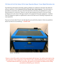
GO TO
Table of Contents
16008 North 81st Street • Scottsdale, Arizona 85260 • 480.483.1214 • www.ulsinc.com
2
Table of Contents
Help
0000 - Contact the ULS Technical Support Department
0010 - Spare Parts List with pictures
-
Consumable Supplies
Consumable Parts
Consumable Optics
Optic Accessories
Electrical and Electronic Parts
Other Parts
Maintenance Tools
0020 - Performing VersaLaser Service Procedures
Adjustments and Settings
A000 - Safety
A005 - Computer Power Management Configuration
A010 - Laser Power Upgrading
A020 - CPU Initialization / Auto-Z and Rotary Calibration
A030 - Cutting Table Calibration
A040 - Rotary Calibration
A050 - X-axis Arm Alignment Check and Adjustment (Squaring)
A060 - Laser Beam Alignment
A070 - Z-axis Leveling
Component Removal and Replacement
Optics
R000 - Focusing Lens
R010 - Mirror 3
R020 - Mirror 2
R030 - Beam Window
Enclosure and Laser
R100 - Rear Cover
R110 - Electronics Cover
R120 - Rear Side Covers
R130 - Side Covers
R140 - Main Cover and/or Keypad
R150 - Top Door Window
R160 - Exhaust Plenum
R170 - Rulers
X-axis
R200 - X-axis Bearings
R210 - X-axis Belt
R220 - X-axis Idler Pulley
R230 - X-axis Motor and Drive Gear
R240 - X-axis Arm
R250 - X-axis Home Sensor Board and Flex Cable
3
Y-axis
R300 - Y-axis Belts
R310 - Y-axis Idler Pulleys
R320 - Y-axis Drive Gears
R330 - Y-axis Bearings
R340 - Y-axis Motor
R350 - Y-axis Home Assembly Adjustment and Replacement
Z-axis
R400 - Z-axis Motor
Electronics
R500 - Laser
R510 - CPU
R520 - Thermal Sensor Board
R530 - Thermal Snap Switch
R540 - Power Supply(s)
R550 - Air Cleaner Serial Port Board
Accessories
T010 - Rotary Fixture
T020 - Cutting Table
T030 - Computer Controlled Compressed Air Unit
T040 - Computer Controlled Air Cleaner
Photos
P0010 - Front View
P0020 - Rear View, Laser Tube Installed
P0030 - Rear View, Laser Tube Removed
P0040 - Rear View, Electronics Cover Removed
P0050 - Right Side View
Glossary
4
Help
0000 – ULS Technical Support Department
Table of Contents
Technical Support Department
16008 North 81st Street
Scottsdale, AZ 85260
Phone: 480-609-0297
Fax: 480-609-1203
Hours: M – F 8 am to 5 pm
Web: http://www.ulsinc.com
Email: [email protected]
5
Spare Parts List
0010 -
Parts List with Pictures
Table of Contents
Consumable Supplies
850-0001-0
Cleaner - Lens
851-0001-0 Tissue - Lens Cleaning
851-0002-0 Applicators - Cotton Tipped
143-0008-0 Gear - X Axis VLS
143-0009-0 Idler - X Axis VLS
Consumable Parts
143-0007-0 Bearing - X or Y (VLS) Set of 4
143-0017-0
Idler - Y Axis VLS
143-0018-0
Gear - Y Axis VLS
591-0003-4 Belt - Y (4.25 feet) (For 18 inch
Y or X axis)
591-0003-2 Belt Kit (10.6 ft) (for 16x12 &
18x12 field)
591-0003-7 Belt - Y (3.25 feet) (For 12 inch
Y-axis)
6
Spare Parts List
Table of Contents
Consumable Optics
145-0027-4 Beam Window – VLS
145-0056-0 Mirror Assembly #2 VLS
145-0083-0 Lens Assembly 2.0 VLS
Optic Accessories
Focus Tool Assemblies - VLS
145-0075-0 Mirror Assembly #3 VLS
145-0084-0 Lens Assembly 1.5 VLS
7
Spare Parts List
Table of Contents
Electrical and Electronic Parts
100-0017-0 X Axis Motor
100-0018-0 Y Axis Motor
100-0019-0 Z Axis Motor
105-0023-0 Power Supply 48V
(VLS2.30/VLS3.50)
133-0161-0 CPU - VLS2.30/VLS3.50
133-0162-0 Thermal Sensor Board
(VLS2.30/VLS3.50)
133-0087-0 X Axis Home Board Assembly
162-0010-0 Power Cord
350-0046-E Fuse - 10A (110V Ceramic)
350-0047-E Fuse - 10A (220V Ceramic)
370-0053-0 Thermal Snap Switch 50 Deg
791-0001-0 Keypad - VLS
8
Spare Parts List
Table of Contents
Other Parts
270-0065-0 Diffuser - Air Assist
Maintenance Tools
800-0002-0 Allen Key Set
591-0033-0 Belt Pulley - Z Axis
9
Help
0020 – Performing
Service Procedures
Table of Contents
Safety
When performing the procedures in this manual, always be sure to read and understand
the entire procedure before beginning to operate the machine. Follow each step
carefully. Pay special attention to steps requiring the VLS to be unplugged!
Do not attempt to perform any of the procedures outlined in this
manual until you have read and thoroughly understand section
A000 – Safety.
Difficulty
The VLS is a very easy machine to maintain and repair. Most service procedures are
simple to perform and require minimal time and tools. In order to provide some
indication as to the difficulty or involvement of the service procedures in this manual, we
have employed the following system:
Procedure requiring very little time and skill
Procedure requiring a moderate amount of time or skill
A more involved procedure requiring a greater amount of time or skill
Tools
Nearly all the procedures described in this manual can be performed with a minimum of
simple hand tools:
Hex Key Set, Standard (SAE) including sizes:
9/64, 1/8, 7/64, 3/32, 5/64, 1/16, .050
Screwdrivers, including Phillips #1, #0
Lens Cleaning Solution, Cotton Swabs or Lens Tissue
Needle Nose Pliers
10
Adjustments and Settings
A000 – Safety – PLEASE READ!
Table of Contents
Description of Appropriate Use
This device is designed for laser cutting and engraving of the materials listed in the VLS
printer driver. Materials to be processed must fit completely inside the system for
proper operation. Use of the equipment in a manner other than that described in this
manual may result in injury to yourself and others and may cause severe damage to the
equipment and your facility.
General Safety
•
Exposure to the laser beam may cause physical burns and can
cause severe eye damage. Proper use and care of this system are
essential to safe operation.
•
Never operate the laser system without constant supervision
of the cutting and engraving process. Exposure to the laser
beam may cause ignition of combustible materials and start a fire.
A properly maintained fire extinguisher should be kept on hand at
all times.
•
Never leave materials in the laser system after laser processing
has finished. Materials may ignite after laser processing has
finished. Thoroughly inspect the interior of the laser system and
remove any particulate materials before leaving your workstation. A
properly maintained fire extinguisher should be kept on hand at all
times.
•
A properly configured, installed, maintained, and operating particulate/fume
exhaust system is mandatory when operating the laser system. Fumes and
smoke from the engraving process must be extracted from the laser system and
either filtered through the Integrated Exhaust Filtration Module (an optional
accessory) or exhausted outside through a user supplied exhaust system.
•
Some materials, during and after laser processing, may
produce toxic fumes. We suggest that you obtain the Material
Safety Data Sheet (MSDS) from the materials manufacturer. The
MSDS discloses all of the hazards when handling or processing
that material. Some materials continue emitting fumes for several
minutes after laser processing and may pose a health hazard. Avoid using this
device in small, enclosed, or non-ventilated areas.
•
Some materials, during and after laser processing, may produce
corrosive fumes. DISCONTINUE processing any material that
produces signs of chemical deterioration in the laser system such as
rust, metal etching or pitting, peeling paint, etc. Damage to the laser
system from corrosive materials is NOT covered under warranty.
11
Adjustments and Settings
•
•
Dangerous voltages are present within the electronics and laser
enclosures of this system. Although access to these areas is not
necessary during normal use, if it becomes necessary to open one of
these enclosures for service reasons, please remember to
disconnect the power cord from your electrical supply.
•
•
Care should be taken when moving or lifting this device.
Obtain assistance from 1 or 2 additional people when lifting or
carrying (secure motion system and access door). Severe bodily
injury may occur if improper lifting techniques are applied or the
system is dropped.
The power supply cord is the mains disconnect device; the
equipment should be located close to an easily accessible
wall socket outlet. To disconnect the equipment from the supply
mains, the power cord shall be unplugged from the wall outlet or
main power inlet (appliance coupler) of the unit.
This device is specifically designed to comply with CDRH performance
requirements under 21 CFR 1040.10 and 1040.11. CDRH is the Center for the
Devices of Radiological Health division of the Food and Drug Administration (FDA)
in the USA. It also complies with CE (European Community) safety regulations. No
guarantees of suitability or safety are provided for any use other than those specified
by Universal Laser Systems, Inc.
Laser Safety
The device contains a sealed carbon dioxide (CO2) laser in a Class I enclosure that
produces intense invisible and visible laser radiation at a wavelength of 10.6 microns in
the infrared spectrum. For your protection, this enclosure is designed to completely
contain the CO2 laser beam.
CAUTION – Use of controls or adjustments or performance of procedures other
than those specified herein may result in hazardous radiation exposure.
•
•
•
•
The intense light that appears during the engraving or cutting process is the product
of material combustion or vaporization. DO NOT STARE AT THIS LIGHT FOR
EXTENDED PERIODS OR ATTEMPT TO VIEW IT WITH OPTICAL
INSTRUMENTS.
This device contains a visible Red Dot Pointer (Class IIIa, 5mw maximum output,
630-680 nm). DO NOT STARE AT THIS RED LIGHT FOR EXTENDED PERIODS
OR ATTEMPT TO VIEW IT WITH OPTICAL INSTRUMENTS.
The user access door of this device is safety interlocked and will disable the CO2
laser beam when the access door is opened. The Red Dot Pointer is NOT safety
interlocked and is activated when the user access door is open.
DO NOT OPERATE THE LASER SYSTEM IF ITS SAFETY FEATURES HAVE
BEEN MODIFIED, DISABLED OR REMOVED. This may lead to exposure to
invisible and visible CO2 laser radiation which may cause permanent blindness
and/or severe burns to the skin.
12
Adjustments and Settings
A005 - Computer Power Management Configuration
Table of Contents
Power management is an option on computers and monitors to reduce energy
consumption when they are not in active use. However, your computer is a critical
component in the operation of the VLS. Active Power Management can cause
interruption of communication between the PC and the VLS, resulting in failure of
operation.
1. With your computer fully booted into
Windows XP, right-click on your
desktop.
2. From the list of options, select
“Properties”.
The
“Display
Properties” box will open.
3. In Display Properties, select the
Screen Saver tab. Set the Screen
saver to “(None)”.
4. Then in the box “Monitor power”,
Click the button “Power…”
13
Adjustments and Settings
5. Select the tab “Power Schemes”.
6. For the “Settings for Home/Office
Desk power scheme” box, select
“Never” for all the setting options:
Turn off monitor, Turn off hard
disks, System standby, and System
hibernates.
7. Click “Apply”, then “OK” on both
open windows.
8. The configuration is complete.
14
Adjustments and Settings
A010 – Laser Power Upgrading
Table of Contents
The VLS2.30 is capable of upgrading to a maximum of 30 watts. The VLS3.50 is
capable of upgrading to a maximum of 50 watts.
If you are upgrading either system, the VLS’s internal software (firmware) will
automatically reflect the change. Nothing has to be done to the laser system to have it
function properly.
15
Adjustments and Settings
A020 - CPU Initialization / Auto-Z and Rotary Calibration
NOTE: This procedure must be performed with the solid aluminum Engraving
Table installed. Do not use the honeycomb Cutting Table for this procedure.
Table of Contents
1. Power up your computer and the VLS. Home the Z-axis by clicking the HOME Z
button in the VIEWER tab of the VCP.
2. Using the UP and DOWN arrow buttons, either on the machine or in the UCP,
bring the Z-axis table up. Using the appropriate Focus Tool for the lens installed
(the standard is 2.0, other Focus Lens Kits are optional), focus directly on the
surface of the table.
3. In the UCP, click the SYSTEM tab and choose 2.0 from the Lens Size list.
16
Adjustments and Settings
4. Click on the Calibrate button within the Lens Size box of the System Tab. The
following window appears. Click on Save to accept the new Z Position. Your 2.0
Lens has now been calibrated.
5. If you have purchased the 1.5 or HPDFO optional lens kits, calibrate the lens kit
according to steps 1 through 4. Be sure you select the proper lens size from the
list before calibrating.
6. You must now set the Y-axis Rotary Position even if you have not purchased the
optional Rotary Fixture.
17
Adjustments and Settings
7. Lower the Z-axis table, halfway down. 8. Locate the Rotary Fixture Alignment
Loosen the two thumbscrews on the
Pin. Then raise the Z-axis platform as
Engraving table and remove.
high as it will go.
9. Using the focus feature in the VIEWER tab of the VCP, position the red dot directly
in the center of the Rotary Fixture Alignment Pin. Try to get is as close to the
center of the pin as possible. You can also use your keyboards arrow keys to
move the focus carriage to an exact location.
18
Adjustments and Settings
10. DO NOT exit the focus feature. While still on the focus feature click on the
SYSTEM Tab and click on the Rotary Calibrate button. The Rotary Calibrate
window appears. Click on the Save button for the Y Position. Accept the new
position.
11. CPU Initialization is now complete.
CPU calibration is necessary for two reasons: You must have a “0.00” reference point
so that the machine properly adjusts the Z-axis to focus the laser beam accurately when
selecting the different lenses. Also, it needs to know where the centerline of the Rotary
Fixture is so that the x-axis arm will move out to the correct position (highest point of the
cylinder) to engrave cylindrical objects.
19
Adjustments and Settings
A030 - Cutting Table Calibration
Table of Contents
Installation
1. Turn on your VLS machine by clicking on the red POWER button on your Universal
Control Panel.
2. Lower the table all the way down to the bottom of its travel or down far enough so
that you can remove the table and install the VCA without interfering with the moving
parts of the VersaLASER.
3. Remove the table by loosening the two captive thumbscrews (1). Insert your
fingers into the two holes (2) and slowly lift the table out of the VersaLASER being
careful not to bump it around. On the underside of the VCA find the self-aligning
electrical connector (3) and two alignment holes (4).
4. Inside the VersaLASER you will find 5. By using the thumbscrews as handles
the large recessed slot with a self(3), insert the VCA into the slot (it is
aligning electrical connector to the
OK to do with the power on because it
right side (1) and the two alignment
is hot swappable) and move it around
pins (2).
until the connector engages and the
fixture sits flat. DO NOT raise the
table at this point.
20
Adjustments and Settings
Focus Lens Calibration
To properly use the VCA for the first time you NEED to calibrate
your focus lens to the top of the VCA surface. If you do not
calibrate the focus lens the focus carriage may cause damage to
your VCA and focus carriage.
6. After you have installed the VCA into your
VersaLASER, manually focus to the VCA
surface by using your appropriate focus tool.
7. Once that is complete, go directly to your
System Tab and you will notice that the red
CALIBRATE button for the Cutting Table box
will be activated. Click on the CALIBRATE
button. A window will appear. To accept the
new Z-height click on SAVE.
8. You are now done calibrating the new Zheight for engraving or cutting on the VCA.
21
Adjustments and Settings
A040 - Rotary Calibration
Table of Contents
Calibration and Installation
1. Turn on the UCP and VLS.
2. Open the top door.
3. Lower the table all the way DOWN to the bottom of its travel so that you can remove
the table.
4. Remove the table by loosening the 5. Inside the VersaLASER you will find
two captive thumbscrews (1). Insert
the large recessed slot with a selfyour fingers into the two holes (2) and
aligning electrical connector to the
slowly lift the table out of the
right side (1) and the two alignment
VersaLASER being careful not to
pins (2)
bump it around
6. Now raise the Z-axis platform as high as it will go by using the VLS keypad or UCP.
22
Adjustments and Settings
7. Proceed to the UCP and activate the focus feature on the right hand side of the
Viewer Tab. Click within the focus feature and have the focus carriage move over
the alignment pin as shown. Use the red LED to position the focus carriage over
the pin properly. You can also use your computers keyboard to control the
movement of the focus carriage when you are using the focus feature. DO NOT
exit the focus feature yet.
8. Next, proceed to the System Tab and
click on the Rotary CALIBRATE
button. The Rotary Calibration
window appears. Click on the Y
Position SAVE button. If it asks you to
override the current position accept
the new number. Once the Rotary
Calibration window is closed the focus
carriage will re-home.
9. Go back to the Viewer Tab and exit the focus feature.
10. Lower the table all the way DOWN to the bottom of its travel.
23
Adjustments and Settings
11. On the underside of the Rotary notice 12. Insert the Rotary into the slot (OK to
do with the power on because it is hot
the self-aligning electrical connector
swappable) and move it around until
(1) and two alignment holes (2).
the connector engages, the pins
protrude through the alignment holes,
and the fixture sits flat. It will indicate
that it is installed properly by
automatically rotating its cone slightly.
13. Using the same procedure in step 7 14. Once you have manually focused
proceed to the System Tab and click
use the focus feature and move the
on the Rotary CALIBRATE button.
focus carriage’s red LED over the flat
The Rotary Calibration window
part of the metal concave fixture. Now
appears. Click the SAVE button for
use the focus tool and manually focus
the Z Position ONLY. If it asks you to
on top of the flat part of the metal
override the current position accept
concave fixture. DO NOT focus on
the new number.
top of the black metal cover normally
located on the left hand side of the
rotary.
15. Rotary calibration is now done. Rotary calibration does not been to be done again
unless the VLS’s CPU is changed or calibration settings are changed.
24
Adjustments and Settings
A050 - X-axis Arm Alignment Check and Adjust (Squaring)
Table of Contents
1. Make sure the VLS is powered OFF and unplugged.
2. Open the Top Door.
3. Locate the pins that are pressed
into the Y-axis Rails. There are
two pins, one on each rail, in the
rear corners of the main
enclosure.
6. Remove the Rear Cover.
7. Remove the Laser Tube.
4. Gently push the X-axis Arm all the
way to the back. Observe if both
sides of the arm touch the two
respective pins, at the same time.
You may need a flashlight to see
the pins. If you cannot, make a
judgment by the gap between the
arm and the rear wall.
5. If one side touches one pin, and the
other side doesn’t, the arm is not
square and you will need to
proceed to step 6. If the arm
touches both pins you are done with
this process.
25
Adjustments and Settings
8. Locate the Y-motor from the rear of
the machine.
9. Choose one of the four motor shaft
coupler screws and loosen it.
10. Standing on the side of the
machine, with one hand push the
arm towards the pins and hold it
there firmly. With the other hand,
tighten the coupler screw that you
loosened.
Tighten the other 3
coupler screws just in case they
are loose. You may need the
assistance of another person.
11. Reassemble the system.
12. If the X-axis arm continues to come out of square, then either the Y-axis Belt is loose
or worn excessively or the Y-axis Drive Gear is slipping. Proceed to those sections
and then perform this procedure again.
26
Adjustments and Settings
A060 - Laser Beam Check and Alignment
Table of Contents
Make sure the table is clear of any objects that could obstruct the
movement of the motion system. The red diode is ONLY a guide. The
red diode may be slightly off center compared to the burn mark you will
make in the following steps so we recommend you make a burn mark for
best results.
1. Power the VLS ON and let it home, or
re-home it by clicking the Home XY
button in the Viewer Tab of the UCP.
2. Remove the optics from the Focus
Lens Carriage and place in a safe,
clean place.
3. Place a strip of masking tape over the
hole on the left side of the Focus
Carriage.
4. The red diode beam should appear
on the tape. The red diode beam
should be fairly centered over the
hole.
27
Adjustments and Settings
5. Using the Focus Feature (1) of the Viewer Tab in the UCP, verify the position of
the red diode beam relative to the hole in the focus carriage in all four corners of
the table.
6. The red diode should be fairly centered on the hole in all four corners of the table. If
this is the case, you can remove the masking tape from the hole in the focus
carriage and reinstall the optics. The laser beam is aligned.
7. If the red diode beam is not centered on the hole in all four corners of the table, the
beam will need to be aligned. Do not remove the masking tape or reinstall the optics.
8. Power off the VLS and unplug the unit.
9. Slowly move the X-axis arm (1)
forward.
10. Locate and carefully remove the two
screws securing the cover on the
left-hand side of the X-axis arm.
Remove this cover.
28
Adjustments and Settings
11. Plug in the VLS and turn the power on with the top door open.
12. Once it finishes homing proceed to the System Tab then click on the Alignment
Launch button. The Alignment Mode window will appear.
13. Click on the upper left hand Move
button. The VLS’s focus carriage will
move to the indicated X, Y position.
14. With the cover removed, locate the three adjusting screws on the #2 Mirror mount
on the left-hand side of the X-axis arm. Turn these screws to center the red dot
diode.
Note: To create a small burn mark on the tape in the next step you will need to adjust
your Power and Seconds settings in the Alignment Mode screen (lower left side).
Lower power laser tubes require higher power settings and higher power laser tubes
require lower power settings to make the burn mark on the tape.
15. Adjust the Power and Seconds 16. Close the top door if it’s not already
settings on the lower left side of the
closed and then click on the Activate
Alignment Mode window. Start of with
Laser button.
5% Power and 2 Seconds.
29
Adjustments and Settings
17. If the burn mark is not centered adjust the corresponding screw on the #2 Mirror
mount.
18. If the burn mark is centered continue to step 20.
19. Continue making a burn mark on a new piece of tape until the burn mark is fairly
centered on the upper left hand corner.
20. Once the burn mark is centered keep the piece of tape on the focus carriage.
21. Now click on the lower right side Move 22. Close the top door if it’s not already
button.
closed and then click on the Activate
Laser button. Take note of the burn
mark.
23. Both burn marks should be over lapping each other near the center. If they are not
continue to adjust the #2 Mirror for the lower right hand corner.
24. Once aligned Exit the Alignment Mode Window and remove the masking tape from
the Focus Lens Carriage and reinstall the optics.
25. Power off and unplug the VLS.
26. Reinstall the cover and two screws over the #2 mirror mount from step 10.
30
Adjustments and Settings
A070 - Z-axis Leveling
Table of Contents
1. Power ON the VLS.
2. Using the Focus tool manually set
the focus height to the engraving
table.
3.
4.
5.
6.
Power OFF and unplug the laser system.
Remove the Rear Cover.
Remove the Rear Side Covers.
Remove the Side Covers.
7. Locate the four pulleys, one at the
bottom of each lead screw. Two
pulleys with lead screws are on
each side of the machine.
31
Adjustments and Settings
Table to low
Table to high
8. Move the focus carriage to each of
the four corners of the table by
hand. At each corner, use the
Focus tool to check the height of
the table to the Focus carriage.
9. Locate the corner (or corners) of the
table that are “off”, i.e. either too
close or to far from the Focus
carriage.
10. One at a time, locate the pulley of
the lead screws that are “off”.
11. If necessary, rotate the pulley to
find the screw at the base shown
above.
12. Loosen the pulley screw.
13. After the screw is loose, you can
adjust that corner of the table
independently from the rest of the
table by turning that lead screw by
hand.
14. Use the focus tool to measure the
changing height of the corner you
are adjusting until it is exactly
correct.
15. Repeat this process with all other corners that are out of level.
16. Check to make absolutely certain that each of the pulley screws is firmly tightened.
17. Replace all of the covers.
32
Component Removal and Replacement
R000 – Focusing Lens
Table of Contents
1. Make sure the VLS is powered OFF and unplugged.
2. Slowly slide the X-axis Arm (1)
forward.
3. Grasp the bottom lip (2) of the
cover.
4. Rotate the cover (1) up and over
the top of the X-axis Arm. The cover
is held down by magnets and will
“stick” slightly when you first begin
to pull it upward.
5. Locate the Focus Carriage (1).
6. Loosen the two thumbscrews
completely (2).
They are held
captive by retaining clips so they
will not come out all the way.
7. Grasp the Front Cover Plate (3).
Gently slide it forward and out of the
Focus Carriage to remove the
optics.
8. Place the optics on a soft, nonabrasive cloth.
9. Remove the two Phillips head
screws (1) that attach the Focusing
Lens to the Front Cover Plate and
remove the optic.
10. Attach the new Focus Lens to the
Front Cover Plate.
11. Clean the #3 Mirror (2) if necessary.
12. Reinstall the optics in the Focus
Carriage.
33
Component Removal and Replacement
R010 - Mirror 3
Table of Contents
1. Make sure the VLS is powered OFF and unplugged.
2. Slowly slide the X-axis Arm (1)
forward.
3. Grasp the bottom lip (2) of the
cover.
4. Rotate the cover (1) up and over
the top of the X-axis Arm. The cover
is held down by magnets and will
“stick” slightly when you first begin
to pull it upward.
5. Locate the Focus Carriage (1).
6. Loosen the two thumbscrews
completely (2).
They are held
captive by retaining clips so they
will not come out all the way.
7. Grasp the Front Cover Plate (3).
Gently slide it forward and out of the
Focus Carriage to remove the
optics.
8. Place the optics on a soft, nonabrasive cloth.
9. Remove the two Phillips head
screws (1) that attach Mirror 3 to
the Front Cover Plate and remove
the optic.
10. Attach the new Mirror 3 to the Front
Cover Plate.
11. Clean the Focus Lens (2) if
necessary.
12. Re-attach to the Focus Carriage.
34
Component Removal and Replacement
R020 - Mirror 2
Table of Contents
1. Make sure the VLS is powered OFF and unplugged.
2. Slowly slide the X-axis Arm (1)
forward.
3. Grasp the bottom lip (2) of the cover.
4. Rotate the cover (1) up and over the
top of the X-axis Arm. The cover is
held down by magnets and will “stick”
slightly when you first begin to pull it
upward.
5. Locate Mirror 2 on the left side of the
X-axis arm.
6. Grasp its protruding handle with your
thumb and forefinger and slide it out.
It is held in place by magnets so you
may feel a slight resistance when you
begin to slide it out. The next photo
shows the backside of the mirror.
7. Install the new Mirror 2 by sliding it
into the mounting slot until it stops.
NOTE:
Installing
the
mirror
backwards will cause the handle
to protrude in such a way that the
X-axis Arm cover will not close
properly and will destroy the
mirror once the laser beam
penetrates the backside of the
mirror, so be sure that you reinstall the mirror correctly.
35
Component Removal and Replacement
R030 - Beam Window
Table of Contents
NOTE: Be very careful not to touch the optical surface of the beam window
during installation or removal.
1. Power OFF and unplug the VLS.
2. Open the top door and pull the Xaxis arm to the front of the machine.
3. The Beam Window is located inside
the Main enclosure to the left as
show above.
5. Installation is opposite of removal.
4. Unscrew the two screws shown to
remove the beam window. Be careful
not to touch the optical surface of the
beam window during removal. Set the
beam window and screws aside.
36
Component Removal and Replacement
R100 - Rear Cover
Table of Contents
1. Make sure the VLS is powered OFF and unplugged.
2. Remove the 2 screws from the
underside of the Rear Cover.
4. Installation is opposite of removal.
3. Lift the cover up and off of the
machine. Store in a safe place.
37
Component Removal and Replacement
R110 - Electronics Cover
Table of Contents
1. Make sure the VLS is powered OFF and unplugged.
2. Remove the Rear Cover.
3. Remove the Laser.
a. Verify that you remove the bracket as stated in Laser before removing the laser
tube.
4. Remove the 2 screws (1) that
attach the Electronics Cover to the
Main Enclosure. Notice that the
rubber grommet (2) is also attached
to the Electronics Cover.
6. Installation is opposite of removal.
5. Carefully lift the Electronics Cover
up and pull it towards you. As you
continue to remove the cover, slide
the rubber grommet off the edge of
the cover. Store the cover in a safe
place.
38
Component Removal and Replacement
R120 – Rear Side Covers
Table of Contents
1. Make sure the VLS is powered OFF and unplugged.
2. Remove the Rear Cover.
3. Remove the Laser.
4. Remove the four stainless
steel socket head screws
and washers (1). Remove
the two button head screws
(2). Detach the rear side
covers and store them in a
safe place.
5. Installation is opposite of removal.
39
Component Removal and Replacement
R130 – Side Covers
Table of Contents
1. Remove the Rear Cover.
2. Remove the Laser.
3. Remove the Rear Side Covers.
4. The side cover is tightly held in
place by the overhanging edges of
the Main Cover and may be difficult
to remove. Slide the side cover, by
placing the palm of your hand
against it, to the rear of the machine
(1). If it does not slide easily, gently
use a flat screwdriver or other
prying device underneath the bent
flange (2) to assist you.
5. If it does not move easily, do not
force it or distort the 90 degree
bend of the cover. IF IT IS TOO
DIFFICULT TO REMOVE THE
SIDE COVER AND YOU FEEL
THAT
YOU
MAY
CAUSE
DAMAGE TO THE COVER, TO
MAKE IT EASIER TO REMOVE,
TRY REMOVING THE MAIN
COVER FIRST.
6. If it moves easily, then when the
side cover starts to move (1), you
will need to pull it down (2) to
release it from underneath the edge
of the front cover. Remove the left
side in the same manner.
7. Take notice of the inside lower lip (1)
of the side cover. This is important
when re-installing it.
8. Installation is opposite of removal.
40
Component Removal and Replacement
R140 – Main Cover and/or Keypad
Table of Contents
1. Make sure the VLS is powered OFF and unplugged.
2. Remove The Rear Cover, Laser, and Rear Side Covers.
3. Remove the Side Covers. If you are having difficulty removing the side covers,
proceed to the next step anyway.
4. Locate and remove the two button
head screws at the bottom front of
the VLS.
6. Open the Top Door (1).
7. Gently lift up on both arms (2).
There may be some binding along
the front side of the Main Cover as
the cover passes over the two Top
Door Interlock Sensors (3).
11. Installation is opposite of removal.
5. Remove the four screws at the top
rear corners of the VLS.
8. Remove the Main Cover slowly.
Take notice of the Top Door
Interlock Sensors (1) and the
Keypad wiring harness (2).
9. Unplug the Keypad wiring harness
from the keyboard.
10. If you are removing the Keypad,
take off the two screws (3) and
detach it from the enclosure.
41
Component Removal and Replacement
R150 - Top Door Window
Table of Contents
1. Make sure the VLS is powered OFF and unplugged.
2. Remove the Rear Cover.
3. Open the top door and locate the 2 hydraulic cylinders and remove the 2
shoulder screws as shown. Hold the top door with one hand while taking the
screws off so the top door won’t drop down. Close the top door.
4. Locate the 2 shoulder screws on the back of the VLS (left and right hand side)
and remove them with an Allen wrench.
42
Component Removal and Replacement
5. While the shoulder screw is being
removed 2 spacers between the main
cover and the top door will drop. Set
the spacers and shoulder screws
aside.
6. Remove the top door from the VLS and place it on a flat surface like a table.
7. Locate the 6 window nuts and remove them with needle nose pliers like shown.
Set the window nuts aside.
8. Carefully turn the top door over and
remove the window frame from the
top door. Using your fingers remove
the glass window from the frame.
The glass window is help in place by
sticky foam tape. DO NOT remove
the sticky tape from the frame.
9. Install the new glass window onto the window frame.
10. Installation is opposite of removal. Verify that you place the spacers back into place
where they were removed from step 5.
11. Plug in and power ON the VLS. Open and close the door. Check to see if the Red
Diode turns on and off when you open and close the door, respectively.
12. Installation is complete.
43
Component Removal and Replacement
R160 – Exhaust Plenum
Table of Contents
1. Power ON the PC and VLS.
2. Home the Z-Axis or use the down arrow button in the UCP or Keypad to lower the
engraving table to the bottom of its travel.
3. Power OFF and unplug the VLS.
4. Remove the table by loosening the
two captive thumbscrews (1). Insert
your fingers into the two holes (2) and
slowly lift the table out of the VLS
being careful not to bump it around.
Move the X-Arm (3) forward.
5. Once the table is removed, carefully
insert your fingers in the slot as shown
and gently pull forward. Next, pull up
on the panel to remove it.
6. Now is a good time to clean the
plenum and exhaust port if required.
7. When reinserting the panel, verify that
the 3 pins are inserted correctly into
the holes and that the panel sits flush
against the wall of the VLS.
8. Installation is opposite of removal.
44
Component Removal and Replacement
R170 – Rulers
Table of Contents
1. To replace the rulers you need a hard plastic scraper and some double-sided
adhesive tape.
2. Use the scraper to gently pry up one of the corners of the ruler and slowly move
down the ruler prying up each section.
3. Once the rulers are removed, use some solvent cleaner to remove any of the tape
residue left over from the removed rulers.
4. Place masking tape on the table over the approximate location of the ruler positions
extending the full length of the table in box axes.
5. Using your graphic software, create a red line box that outlines the page size
perfectly.
6. Run that cut file to see the exact location of where the edges of your rulers should
be.
7. After the cut file has been run, peel the outside masking layer off leaving the inside
portion to set your rulers to.
8. Put the double-sided tape on your new rulers and stick them down to the outside of
the leftover masking tape.
9. Once the rulers are in the correct place, press down firmly on them to ensure they
hold their position.
10. Remove the masking tape from the inside.
45
Component Removal and Replacement
R200 - X-axis Bearings
Table of Contents
1. Power OFF and unplug the VLS.
2. Pull the X-axis arm forward and lift the
arm cover. The cover is held down by
magnets and will “stick” slightly when
you first begin to pull it upward.
3. Carefully move by hand the Focus
Carriage towards the center of the
X-axis arm. Looking down on the
arm with the cover open, you will
see 4 bearings in a square pattern
guiding
the
Focus
Carriage
Assembly along the X-rails.
Order of removal
4. Bearing replacement is easiest if the
Main X-Arm cover is removed first.
Using a ball-end Allen wrench,
remove the 2 screws shown above.
Be careful not to lose the screws or
washers.
5. To remove the bearings, first remove
the two rear bearings (1 and 2). With
these two removed, the front
bearings (3 and 4) can then be
easily removed. It is recommended
to use a 5/16” Nut Driver.
46
Component Removal and Replacement
6. Push on the bracket as shown above
to shift the bearing (1) out of the
track. The entire bearing carriage will
tilt and the bearing will tilt away from
the track.
7. With pressure still applied, use the
nut driver to remove the bearing axle
in the center of the bearing.
8. Remove the second rear bearing in
the same way by pushing on the
adjacent bracket and removing the
axle and bearing.
9. With the two rear bearings out, you
can now remove the remaining two
bearings.
47
Component Removal and Replacement
10. Take notice of the Bearing Assembly. 11. Reinstall the two front bearings first.
There is a small wave washer
These were the last two bearings that
between the head of the axle and the
were removed.
bearing. Be careful not lose or
damage this washer. The bearing
itself has no orientation and can be
installed with either surface against
the carriage.
12. Reinstall the top bearings one at a time in the same way they were removed. Push
the bracket back, insert the bearing, and tighten.
13. Finally, reinstall the final top bearing. Push the bracket back, insert the bearing, and
tighten.
14. Replace the X-axis arm cover.
15. This completes the X-axis Bearing replacement procedure.
48
Component Removal and Replacement
R210 - X-axis Belt
Table of Contents
1. Power OFF and unplug the VLS.
2. Pull the X-axis arm towards the
front of the machine.
3. Locate the two small metal covers
at each end of the X-arm.
4. Remove the screws shown above
(the screws are located on the back
of the X-axis arm on both ends).
5. Remove the small end covers on
both sides and lift up the X-axis arm
cover.
6. First taking note of the tension of
the belt, loosen (but do not remove)
the screws on the belt clamps
shown above.
7. Remove the belt once it has been
separated from the clamps.
8. Loosen the four screws shown
above. These mount the X-axis
motor to the arm and also adjust the
belt tension.
9. Move the motor module as far to the
left of the arm as possible.
10. Feed the new belt through the arm,
making sure it is properly positioned
around the drive gear and idler
pulley.
11. Place each end of the belt inside the
belt clamps and tighten.
49
Component Removal and Replacement
12. Pick up the slack in the belt and set
the tension by moving the motor
module to the right and tightening
all four screws down once the
proper tension has been reached.
13. Replace the two end covers and
screws.
50
Component Removal and Replacement
R220 - X-axis Idler Pulley
Table of Contents
1. Power OFF and unplug the VLS.
2. Pull the X-Axis arm forward so you
can reach the back side.
3. Remove the two screws on the left
side of the arm (located on the back
side of the arm shown above).
4. Remove the small cover.
5. Lift the main X-axis arm cover and
locate the idler pulley on the left
side of the X-Axis arm.
6. Remove the screw on top of the
idler pulley.
7. Remove the pulley and replace it
with the new one.
Note: You may need to loosen the X-motor on the right side of the arm to relieve
some tension on the belt, and to re-set the belt tension once the new Idler pulley
is re-installed. (See X-axis Belt)
8. Replace the cover and screws.
51
Component Removal and Replacement
R230 - X-axis Motor and Drive Gear
Table of Contents
1. Power Off and unplug the VLS.
2. Remove the small cover located on
the right side of the X-axis arm by
removing the two screws in the rear
of the arm.
3. Loosen the four screws shown
above to reduce the belt tension. If
you are removing the motor,
remove
these
four
screws
completely.
4. Loosen the screw on the Drive Gear
shown above.
(If you have
problems getting to it, you may
have to remove the main cover)
5. Slide the Drive Gear off of the motor
shaft.
6. Tighten the new gear on the motor
shaft.
7. Slide the motor to the right and
tighten down the mounting screws
once the desired tension is
reached.
8. Replace the cover and two screws.
52
Component Removal and Replacement
R240 - X-axis Arm
Table of Contents
1. Power OFF and unplug the VLS.
2. Remove the Rear Cover, Rear Side Covers, and Side Covers.
3. Underneath the right side of the
machine, remove the Upper Flex
Cable board by unplugging the Flex
Cable (1), unplugging the motor (2),
and removing the 4 screws (3) that
attach the board to the arm.
Remove the screws one at a time
and be careful not to lose the
spacers (white) that are on top of
the board.
4. Once the board is removed, remove
the two screws that attach the Ybelt bracket to the X-axis Arm (4).
5. Underneath the left side of the
machine, remove the screw that
holds the clamp down but do not
detach the clamp from the hose (2).
6. Remove the two mounting screws
that attach the Y-axis belt clamp to
the X-axis Arm (3).
7. Leave the hose attached to the Xaxis arm but use extreme caution
when proceeding to step 8!
53
Component Removal and Replacement
8. Grasp the arm with both hands.
Gently push one side towards the
rear of the machine and pull the
other side towards the front of the
machine. The arm will detach from
the rails but do not pull on X-axis
arm because this will damage your
VLS.
9. With the X-axis arm detached from
the rail, unscrew the air assist
hose using a flathead screwdriver.
10. If you are exchanging arms, transfer the covers and optics from the old arm to
the new one.
11. Installation is opposite of removal.
12. Once installed, perform X-axis Arm Alignment Check and Adjust (Squaring), and
Laser Beam Alignment.
54
Component Removal and Replacement
R250 - X-axis Home Sensor Board and Flex Cable
Table of Contents
1. Power OFF and unplug the VLS.
2. Locate the X-axis Home Sensor
board on the underside back-right
portion of the X-axis arm, just to the
left of the X-motor.
3. Pull the arm forward to access the
Homing Sensor board.
Reach
behind the arm with a 1/16” Hex
wrench to remove the two screws
(you do not have to remove the arm
to complete the replacement).
6. Installation is opposite of removal.
4. Remove the two screws (1) on
either side of the board shown
above.
5. Remove the small flex cable (2)
from the board by pulling on the
connector release tab.
55
Component Removal and Replacement
R300 - Y-axis Belts
Table of Contents
1.
2.
3.
4.
Power OFF and unplug the VLS.
Remove the Rear Cover, Rear Side Covers, and Side Covers.
Remove the main cover. (See Main Cover and/or Keypad).
Remove the X-Axis Arm.
5. Locate the Y belt clamps on the
underside of both the Y rails.
8. Remove the screws on the other
side as well.
9. Staple one end of the new Y belt to
the old one and pull it through,
replacing the old one.
10. Remove the stapled end.
11. Place the new belt tightly in the
clamp and put the clamp screws
back into place.
6. Remove the screws shown above
to free the Y belt.
7. Take the clamp off, but do not
remove the belt at this time!
12. Once both belts have been
clamped, use the setscrew shown
above to set the tension. There is
one adjustment setscrew for each
belt.
13. Reassemble the machine.
56
Component Removal and Replacement
R310 - Y-axis Idler Pulleys
Table of Contents
SOME OF THESE PICTURES WERE MADE WITH THE Y-RAILS REMOVED FROM
THE MACHINE. THIS IS FOR VISUAL PURPOSES ONLY. THE RAILS MUST
REMAIN ATTACHED TO THE REAR OF THE MACHINE WHILE YOU SERVICE IT!
1. Power OFF and unplug the VLS.
2. Remove the main cover (See Main
Cover and/or Keypad).
3. Locate the two screws on the inside
of the Y rail.
4. Remove the frame screws to release
the front of the rail from the frame.
DO NOT REMOVE THE ENTIRE
RAIL, ONLY THE FRONT TWO
MOUNTING SCREWS AS SHOWN.
57
Component Removal and Replacement
5. Loosen the setscrew (1) in front of the
Y rail to relieve the Y belt tension.
6. Remove the Phillip head screw (2)
from the Y rail as shown above.
8. Remove the long spacer from the
inside of the idler.
10. Replacement is the opposite of removal.
7. Remove the short spacer from
inside the idler. (You may need to
use a screwdriver to push out the
spacers)
9. Remove the idler and replace it with
the new one.
58
Component Removal and Replacement
R320 - Y-axis Drive Gear
Table of Contents
1. Power up the PC and the VLS. Using the UP/ DOWN arrow buttons, either on the
machine or in the UCP, lower the Z-axis table to the bottom of the enclosure.
2. Power OFF and unplug the VLS.
3. Remove the Rear Cover.
4. Remove the Laser.
5. Remove the Rear Side Covers.
6. Remove the Side Covers.
7. Locate the two Y-axis drive gears,
one on each side of the system.
8. Remove the Main Cover.
9. Remove the Y-axis Motor.
10. Loosen the Y-axis Belt tension by
loosening the setscrew as shown.
11. Loosen the Y-axis Drive
clamping screw shown.
Gear
12. Slide the Y-axis Drive Shafts
inwards towards the center of the
machine. The gears should fall out.
13. Install the new Y-axis Drive gears. Tighten the clamp screws securely.
14. Reinstall the Y-axis Motor.
15. Set the Y-axis Belt tension using the setscrew as shown in Step 11.
16. Replace the Main Cover.
17. Replace the Side Covers, and Rear Side Covers.
18. Replace the Laser.
19. Replace the Rear Cover.
20. Perform the procedure X-axis Arm Alignment Check and Adjust (Squaring).
21. Check Laser Alignment.
59
COMPONENT REMOVAL AND REPLACEMENT
R330 - Y-axis Bearings
Table of Contents
1. Power OFF and unplug the VLS.
2. Remove the Main Cover.
3. Remove the X-axis Arm Cover and
remove the arm itself. See the
procedure X-axis Arm.
4. Locate the Y bearings on either side
of the X Axis arm shown above.
5. Remove the nuts in the center of
the Y bearings on the left of the Xaxis arm as shown above.
6. Take off the Y bearings and
replace them with the new ones.
Be careful not to lose the small
wave washers.
7. Remove the nuts in the center of the Y
bearings on the right of the X-axis arm
as shown to the left.
8. Remove the Y bearings and replace
them with the new ones. Be careful
not to lose the small wave washers.
9. Reinstall the X-axis Arm.
10. Reinstall the Main Cover.
11. Reinstall the X-axis Arm Cover.
12. Perform X-axis Arm Alignment Check and Adjust (Squaring), and Laser Beam
Alignment.
60
Component Removal and Replacement
R340 - Y-axis Motor
Table of Contents
1. Power OFF and unplug the VLS.
2. Remove the Rear Cover and the Laser tube.
3. Remove the Electronics Cover.
4. Loosen the coupler screws that
attach the motor to the Y-shafts. Slide
the couplers outwards, away from the
motor.
5. Unplug the motor cable (1) from the
CPU board (2).
6. Remove the 2 screws that hold the
motor bracket to the frame, and
remove the motor and motor bracket.
7. Remove the 4 screws that mount the motor to the bracket and transfer the new
motor to the bracket.
8. Install the new motor and perform the procedures X-axis Arm Alignment Check and
Adjust (Squaring), and Laser Beam Alignment.
61
Component Removal and Replacement
R350 - Y-Axis Home Assembly Adjustment and Replacement
Table of Contents
Adjustment
1. Turn off and unplug your VersaLASER.
2. Do an X-axis Arm Alignment Check and Adjust (Squaring). Once squaring is
complete proceed to the next step.
3. Verify that the magnet is in the proper location. There is a magnet on the right YAxis rail located inside the VersaLASER. If the magnet is missing replace the
magnet. The magnet should not stick out from the Y-Axis rails and should sit flush
against the rail.
4.
5.
6.
7.
8.
9.
Next adjust the Y-Axis Home Assembly board by following the next steps.
Remove the Rear Cover.
Remove the Laser Tube.
Remove the right Rear Side Cover.
Remove the right Side Cover.
Locate the Y-Axis Home Assembly.
a. The Y-Axis Home Assembly is located underneath the y-axis rail on the right
hand side.
62
Component Removal and Replacement
10. Loosen the 4 screws but do not
remove.
11. Gently slide the Y-Axis Home
Assembly towards yourself.
a. The Y-Axis Home Assembly can
only be moved about ¼ inches.
12. Tighten the 4 screws.
13. Attempt to re-home the VersaLASER.
14. If this process does not resolve the problem you will need to proceed to the next
step and replace the Y-axis Home Assembly.
Replacement
a.
b.
1. To remove the Y-Axis Home Assembly you will need to gently unplug the 10-pin,
4-pin, and white connector.
a. The 10-pin and 4-pin connectors are located underneath the PCB board.
b. The white connector is located on top of the PCB board towards the inside of
the VersaLASER.
63
Component Removal and Replacement
2. Remove the Y-Axis Assembly by
unscrewing the screws and set the YAxis Assembly and screws aside in a
clean safe place.
3. Installation of the Y-Axis Home Assembly is opposite of removal.
4. Once the new Y-Axis Home Assembly is installed, re-home the VersaLASER to
ensure the installation was done properly.
a. Make sure all connections and screws are properly installed.
b. You may want to repeat steps 9 through 12 from the above section if re-homing
was not successful.
64
Component Removal and Replacement
R400 - Z-axis Motor
Table of Contents
1. Power OFF and unplug the VLS.
2. Remove the Rear Cover, Right Rear
Side Cover and Right Side Cover.
The Z-axis motor is located on the
right side of the VLS as shown above.
It is not necessary to remove the left
side covers.
3. When performing this procedure,
make sure that you do not
accidentally turn the Z-axis Lead
Screws that drive the table up and
down; otherwise you will need to relevel the table later on!
4. Loosen the two screws (1) to release
the belt tensioner.
5. Slide the tensioner to the left,
releasing the tension (2).
6. Disconnect the electrical connector
(3).
7. Carefully remove the 4 screws that
mount the motor (4) (one is not visible
in the photo) and remove the motor.
8. Transfer the pulley from the old Z-axis Motor to the new one.
9. Install the new Z-axis motor and tighten the 4 mounting screws. Make sure that the
pulley does not contact the base of the machine and can turn freely.
10. Pull the tensioner to the right to re-apply tension to the belt while tightening the
tensioner screws.
11. Reattach the electrical connector.
12. Replace the covers in reverse order of removal.
65
Component Removal and Replacement
R500 - Laser
Table of Contents
Note: Handle the laser with care! Do not bump or jar it.
1. Make sure the VLS is powered OFF and unplugged.
2. Remove the Rear Cover.
3. Unplug the electrical connector (1)
from the Laser by manually undoing
the two thumb screws and gently
pulling it to the left. Remove the two
screws (2) that attach the Laser to
the frame.
Finally remove the
bracket (3) by unscrewing the 2
screws that hold the bracket in
place.
5. Installation is opposite of removal.
4. Rotate the laser, a few degrees,
from the bottom and lift it up and off
the mounts. Store the laser in a
safe place.
66
Component Removal and Replacement
R510 - CPU
Table of Contents
1.
2.
3.
4.
Make sure the VLS is powered OFF and unplugged.
Remove the Rear Cover.
Remove the Laser.
Remove the Electronics Cover.
5. Locate the CPU.
Note the
arrangement of connectors and the
four mounting screws.
6. As a precaution, using masking
tape, label each connector, as in
the photo. Remove the connectors
by pulling them straight up.
Connection labeled number 3
needs to be pulled out to the left.
Also remove the gray colored flat
ribbon cable (9) by pulling the
connector straight up. Carefully
note the orientation of the ribbon
cable connector on the CPU!
Remove the four mounting screws
(10). To prevent static damage,
grasp the CPU board by the edges,
remove the CPU from the system
and store in a safe place.
7. Installation is opposite of removal.
8. Perform the procedure CPU Initialization / Auto-Z and Rotary Calibration.
67
Component Removal and Replacement
R520 – Thermal Sensor Board
Table of Contents
1.
2.
3.
4.
Make sure the VLS is powered OFF and unplugged.
Remove the Rear Cover.
Remove the Laser.
Remove the right side, Rear Side Cover. This is the right side when facing the front
of the VLS.
5. Remove connectors 1, 2, and 3 off
the board.
Carefully note the
orientation of the ribbon cable (1)
connector on the board. Remove
the socket head screw (4). Grasp
the board by the sides and pull the
board straight back towards you.
Be careful not to bump the board
around.
6. Turn the board around and note the
two notches (1).
7. When installing the new board, make sure the notches align with the alignment pegs
mounted in the main enclosure. Re-attach the socket head screw and the electrical
connectors to finish the installation.
68
Component Removal and Replacement
R530 – Thermal Snap Switch
Table of Contents
1. Make sure the VLS is powered OFF and unplugged.
2. Remove the Rear Cover.
3. Remove the Laser.
4. Remove the Thermal Sensor Board’s battery holder by inserting a flat head screw
driver into the slot of the battery holder. Gently push up then pull the screw driver
towards you to remove the battery holder and set it aside.
5. Located behind the laser tube,
undue the 2 screws shown and set
aside.
6. Grab a hold of the bracket and
gently pull up and out. You may
have to rotate the bracket and slide
it out sideways. Be careful not to
pull on the bracket as it is still
attached.
69
Component Removal and Replacement
7. First, unplug the wire connectors by
gently pulling the connector out.
Once that is done, unscrew the 2
screws that hold the switch to the
bracket and set those aside.
8. Installation is opposite of removal. Verify that the battery is reinstalled into the VLS
in order for the engraver to function properly.
70
Component Removal and Replacement
R540 - Power Supply(s)
Table of Contents
Note: The VLS3.50 and VLS2.30 is shown in the following photos. The VLS2.30
only has one power supply and the VLS3.50 has two power supplies.
1.
2.
3.
4.
5.
6.
Power OFF and unplug the VLS.
Remove the Rear Cover.
Remove the Laser.
Remove the Rear Side Covers.
Remove the Electronics Cover.
Remove the CPU and set it aside.
7. Disconnect the power supply inlet
connectors. Label them if necessary.
8. Disconnect all of the connections to
the power supply(s) and label them if
necessary.
9. Remove the screws on the ends
holding the electronics mounting
plate to the frame.
10. Remove the electronics mounting
plate from the frame.
71
Component Removal and Replacement
9. Remove the screws that hold the 10. Turn over the electronics mounting
plate and remove the screws holding
cables onto the power supply
the power supplies.
connection behind the first power
supply (if you have a VLS3.50).
11. Installation is opposite of removal.
72
Component Removal and Replacement
R550 – Air Cleaner Serial Port Board
Table of Contents
1. Unplug the Air Cleaner Cart.
2. Remove the 4 screws mounting the
upper blower cover and remove the
cover.
3. Detach the hoses at the quick
connect points.
4. Remove the 2 screws shown above
and carefully tip the motor box over
to expose the Serial Port Board.
5. Once the inside of the box is
exposed cut the hoses where
indicated as in the above picture and
pull the hoses back through the
plate. Pay close attention to the
order the hoses are in.
73
Component Removal and Replacement
6. Remove the 4 screws holding the
Serial Port Board.
7. Remove the wire connector on the
right and remove the board.
8. Install the new board and reconnect.
9. Pass the new hoses back through
the plate and insert the quick
connect fittings into the ends of the
new hoses.
10. Installation is opposite of removal.
74
Accessories
T010 - Rotary Fixture
Table of Contents
Question
Answer
What kinds of operational checks can I do to ensure that my Rotary Fixture is
working right?
-
Make sure that when you install the
rotary in the table socket that the cone
briefly rotates.
Verify that you have calibrated the
rotary using the “Calibrate” feature in
the UCP.
Be sure to have “Rotary” selected in
the Fixture Type selection of the
printer driver.
What kind of adjustments can I make help optimize my Rotary fixture?
-
Always check the focus of each object
being engraved with the rotary.
Measure the diameter accurately and
enter the value in the driver.
What if my system will not detect the Rotary Fixture?
-
Be sure the rotary has been set into
the table socket connector completely.
Be sure that “Rotary” is selected in the
Fixture Type selection of the printer
driver.
What is the best way to clean and maintain my Rotary Fixture?
Use light industrial cleaner to keep the
cone clean and the base free of
debris.
75
Accessories
T020 - Cutting Table
Table of Contents
Question
Answer
What kind of operational checks can I do to ensure that my Cutting Table is
working correctly?
-
Verify that the Cutting table fixture is
in all of the way in the table socket
and that it is level.
Be sure to have “None” selected in the
Fixture Type selection in the printer
driver.
Verify that you have calibrated the
cutting table using the “Calibrate”
feature in the UCP.
What kind of adjustments can I make to help optimize my Cutting Table?
Keep the honeycomb insert fairly
clean and free of debris.
What if my system will not detect the Cutting Table?
-
Make sure that the table is installed in
the table socket connector correctly.
Make sure that you have “None”
selected in the Fixture Type selection
in the printer driver.
What is the best way to clean and maintain my Cutting Table?
-
Empty out all of the debris from cutting
every four hours of use.
Maintain the exhaust flow.
Clean or replace the honeycomb
insert when it becomes restrictive to
the exhaust flow.
76
ACCESSORIES
T030 - Computer Controlled Compressed Air Unit
Table of Contents
Question
Answer
What kind of operational checks can I do to ensure that my Air Assist Compressor Unit is working correctly?
-
Verify all the connectors are in place.
Check for a green light on the unit
showing communication between the
devices.
Verify that that the unit switches ON at
the start of a file.
What kind of adjustments can I make help optimize my Air Assist Compressor Unit?
-
Keep all of the air filters on the unit
clean.
Make sure that the unit is in a place
where air circulates well to keep the
core temperature down.
What if my system will not detect the Air Assist Compressor Unit or it will not come
on?
-
Verify that all hoses and connections
are in place.
Check the green light communication
indicator.
What is the best way to clean and maintain my Air Assist Compressor Unit? -
Keep all air filters clean on the unit.
Keep a steady flow of air around the
perimeter of your compressor unit.
77
ACCESSORIES
T040 - Computer Controlled Air Cleaner
Table of Contents
Question
Answer
What kind of operational checks can I do to ensure that my Computer Controlled
Air Cleaner is working correctly?
-
What if my system will not detect the Computer Controlled Air Cleaner or it will
not come on or there are problems with the suction?
-
What is the best way to clean and maintain my Computer Controlled Air Cleaner?
Check and maintain the saturation of
all filters.
Keep the filter drawers completely
closed to avoid any stray particulates.
Keep all laser exhaust ports clean.
Check the green light communication
indicator.
Check all connections for power.
Unplug the Serial connection and shut
down the computer attached to the
VersaLASER. Once the system shuts
down plug the Serial connection back
in and restart the computer.
Call tech support for any driver
updates.
Make sure all drawers and lids are
closed properly to create a proper
seal.
Keep all air filters clean on the unit.
Keep the exhaust ports well
maintained and clean to avoid excess
buildup.
78
PHOTOS
P0010 - Front View
Table of Contents
1 – FOCUS CARRIAGE
2 – #2 MIRROR
3 – ENGRAVING TABLE
4 – X-ARM
5 – X-ARM COVER
6 – TOP DOOR/ WINDOW
7 – X-MOTOR
8 – MAIN COVER
9 – REAR COVER
79
PHOTOS
P0020 - Rear View, Laser Tube Installed
Table of Contents
1 – LASER TUBE
2 – LASER MOUNTING SCREWS (2)
3 – LASER ELECTRICAL CONNECTOR
4 – REAR SIDE COVERS (2)
5 – TOP DOOR ENCLOSER
6 – MAIN COVER
7 – TOP DOOR WINDOW
8 – AC POWER INPUT CONNECTOR
9 – THERMAL SENSOR BATTERY
80
PHOTOS
P0030 - Rear View, Laser Tube Removed
Table of Contents
1 – ELECTRONICS COVER
2 – BEAM TUBE
3 – Y-AXIS MOTOR COUPLINGS (2)
4 – Y-AXIS MOTOR
5 – LASER ELECTRICAL CONNECTOR
6 – THERMAL SENSOR
81
PHOTOS
P0040 - Rear View, Electronics Cover Removed
Table of Contents
1 – 48VDC POWER SUPPLY
(VLS3.50 – TWO SUPPLIES, VLS2.30 – ONE SUPPLY)
2 – CPU
82
PHOTOS
P0050 – Right Side View
Table of Contents
1 – REAR COVER
2 – REAR SIDE COVER
3 – SIDE COVER
4 – MAIN COVER
1 – ELECTRONICS COVER
2 – CPU-RIBBON CABLE
3 – CPU
4 - THERMAL SENSOR BATTERY
5 – THERMAL SENSOR BOARD
6 – Z-AXIS HOME SENSOR
7 – Z-AXIS BELT TENSIONER
8 – Z-AXIS MOTOR
9 – Z-AXIS LEAD SCREW PULLEY (4 EA)
10 – Z-AXIS LEAD SCREW (4 EA)
11 – X-AXIS MOTOR
12 – Y-RAIL (2 EA)
13 – MAIN COVER
83
GLOSSARY
GLOSSARY
Table of Contents
#2 Mirror – A mirror located at the far left side of the X-axis Arm used to direct the
horizontal laser beam from the Beam Window into the Focus Carriage.
#3 Mirror – A mirror located in the Focus Carriage used to direct the horizontal laser
beam downward onto the work piece.
Air Assist Cone – An accessory for the VersaLaser which attaches to the Focus
Carriage to direct compressed air on to the surface of the work piece. On some
materials it can be used to reduce the burning effects of the material from laser beam’s
intense heat. It also can help disperse smoke and gasses created by processing of
some materials.
Back Sweep - An accessory for the VLS which attaches to the Focus Carriage to flow
compressed air on to the surface of the work piece, either directly or at an angle. On
some materials it can be used to reduce the burning effects of the material from laser
beam’s intense heat. It also can help disperse smoke and gasses created by processing
of some materials.
Beam Window – An optic mounted in the left hand rear of the enclosure through which
the laser beam enters the enclosure.
CCAC – Computer Controlled Air Cleaner/Cart. An accessory for the VLS that provides
a self-contained, computer-controlled exhaust filtration system.
CCAU – Computer Controlled Compressed Air Unit. An accessory for the VersaLaser
that provides dry, oil-free compressed air for use with the Air Assist Cone and Back
Sweep Accessories.
CPU – A Circuit Board in the VLS that communicates with the PC to drive the motors,
monitor interlocks and sensors, etc.
Cutting Table – An accessory for the VersaLaser with a honeycomb insert used to
support the work piece when vector cutting. Also can be used as a vacuum base for
holding sheet stock flat while cutting.
Diode Beam – The red beam used to indicate the path and position of the cutting/
engraving laser.
Engraving Table – The solid, flat metal plate which supports the work piece.
84
GLOSSARY
Table of Contents
Focus Carriage – The red aluminum housing which houses the Focus lens and #3
Mirror. The Focus Carriage moves back and forth along the X-axis arm when rastering
or vectoring.
Focus Lens – An optic located in the Focus Carriage which concentrates the laser
beam into a very small, highly intense spot for cutting and engraving.
Focus Tool – An important tool supplied with the VLS that acts as a gauge to
accurately set the distance from the Focus Lens to the work piece.
Graphics Program –The software necessary to create the artwork executed by the
VLS. CorelDraw 12 and X3 are two recommended graphics programs.
Interlock – The safety mechanism which prevents the laser beam from being emitted
when the top door is opened.
Laser (Cartridge or Tube) – The laser device which generates the beam used to cut
and engrave the work piece.
Main Enclosure – The “box” in which the x-y-z motion system moves and the work
piece is engraved or cut.
Operating System – The software that runs the computer. The VLS requires Windows
XP or Vista as the PC operating System.
Optic – Any optical element such as a window, mirror or lens.
PC – Personal Computer. The VLS requires a PC as an integral part of its operation.
Raster Engraving – A method of engraving whereby the laser beam is scanned back
and forth, engraving horizontal lines in the work piece as it steps down the work piece
vertically. At each pass a series of laser pulses are applied to create the engraved
image. Similar in action to an inkjet or laser printer.
Red Diode Beam – The red beam used to indicate the path and position of the cutting/
engraving laser.
Rotary – An accessory for the VLS used to engrave or cut cylindrical objects.
USB – Universal Serial Bus. A standardized communications line used to connect
external devices (such as the VLS) to a computer.
85
GLOSSARY
Table of Contents
Thermal Sensor Board – A circuit Board on the VLS into which accessories connect
using a Serial connection. A ribbon cable connects the USB hub to the CPU.
UCP- Universal Control Panel – The software supplied by Universal Laser Systems
used to operate the VLS. This software program allows the user to view, store and
execute jobs. Accessed by clicking
Icon in the System Tray.
Vector Cutting / Engraving – A method whereby the laser beam is made to follow a
path to cut or engrave a desired outline. Similar in action to a pen plotter.
X-arm or X-Axis – The silver metal-covered rail which moves front to back in the Main
Enclosure during rastering or vectoring. The Focus Carriage moves right and left along
this rail.
X-Axis Bearings – The four bearings on the X-axis arm which guide the Focus
Carriage along the arm.
Y-axis – The front to back direction in the Main Enclosure. Also, the mechanical system
used to move the X-axis arm front to back in the enclosure.
Y-axis Bearings – The bearings on the ends of the X-axis arm that guide it along the Yrails.
Y-rails – The two parallel rails which guide the X-arm front and back inside the Main
Enclosure.
Z-Axis – The up and down direction in the Main Enclosure. Also, the mechanical
system used to raise and lower the table on which the work piece is placed.