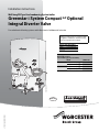
1
Installation instructions Wall hung RSF gas fired condensing System boiler Greenstar i System Compact ErP Optional Integral Diverter Valve For sealed central heating systems and indirect mains fed domestic hot water Read these instructions in conjunction with the appliance Installation, Commissioning and Servicing Instruction manual. Diverter valve kit numbers 27kW 7 733 600 220 30kW 7 733 600 221 6720816348-00.1Wo These appliances are for use with: Natural Gas or L.P.G. (Cat. II 2H 3P type C13, C33 & C53) Model Natural Gas 27i System Compact ErP 30i System Compact ErP L.P.G. 27i System Compact ErP 30i System Compact ErP 6 720 816 348 (2015/03) UK/IE GC Number 41-406-58 41-406-60 41-406-59 41-406-61 Contents Contents 1 Key to symbols and safety instructions . . . . . . . . . . . . . . . . . . . 3 1.1 Key to symbols . . . . . . . . . . . . . . . . . . . . . . . . . . . . . . . . . 3 1.2 Safety precautions . . . . . . . . . . . . . . . . . . . . . . . . . . . . . . 3 2 General information . . . . . . . . . . . . . . . . . . . . . . . . . . . . . . . . . . . 4 2.1 Standard package . . . . . . . . . . . . . . . . . . . . . . . . . . . . . . . 4 2.1.1 DHW temperature control . . . . . . . . . . . . . . . . . . . . . . . . . 4 2.1.2 Electrical diagram . . . . . . . . . . . . . . . . . . . . . . . . . . . . . . . 5 3 Pre-installation . . . . . . . . . . . . . . . . . . . . . . . . . . . . . . . . . . . . . . . 6 3.1 General layout . . . . . . . . . . . . . . . . . . . . . . . . . . . . . . . . . . 6 3.1.1 System layout overview . . . . . . . . . . . . . . . . . . . . . . . . . . 6 3.2 Plumbing manifold . . . . . . . . . . . . . . . . . . . . . . . . . . . . . . 7 3.2.1 Connections . . . . . . . . . . . . . . . . . . . . . . . . . . . . . . . . . . . . 7 3.2.2 Diverter valve kit considerations . . . . . . . . . . . . . . . . . . . 8 3.2.3 Appliance Installation and Commissioning . . . . . . . . . . . 8 3.2.4 Fitting the cylinder flow and return service valves . . . . . 8 4 Installation . . . . . . . . . . . . . . . . . . . . . . . . . . . . . . . . . . . . . . . . . . . 8 4.1 Wall mounting template . . . . . . . . . . . . . . . . . . . . . . . . . . 8 4.1.1 Fixing the wall mounting frame . . . . . . . . . . . . . . . . . . . . . 8 4.1.2 Hanging the appliance . . . . . . . . . . . . . . . . . . . . . . . . . . . . 8 5 Fitting the integral diverter valve kit . . . . . . . . . . . . . . . . . . . . . 9 5.1 Assembly of the internal cylinder pipes to the appliance . . . . . . . . . . . . . . . . . . . . . . . . . . . . . . . . . . . . . . 9 5.1.1 Diverter valve kit plumbing . . . . . . . . . . . . . . . . . . . . . . . . 9 5.2 Fitting the diverter valve motor . . . . . . . . . . . . . . . . . . . . 9 5.3 Access to the HCM (Heating Control Module) . . . . . . . . . 9 5.4 Fitting the HCM (Heating Control Module) . . . . . . . . . 10 5.5 Cylinder temperature sensor installation . . . . . . . . . . 10 5.5.1 Fitting the cylinder temperature sensor . . . . . . . . . . . 10 5.6 Mounting optional plug-in controls . . . . . . . . . . . . . . . . 12 5.6.1 Plug-in programmer/timers . . . . . . . . . . . . . . . . . . . . . 12 5.6.2 EMS controls . . . . . . . . . . . . . . . . . . . . . . . . . . . . . . . . . 12 5.6.3 Remove the blanking plate . . . . . . . . . . . . . . . . . . . . . . 12 5.6.4 Fitting the plug-in controller . . . . . . . . . . . . . . . . . . . . . 13 5.6.5 Secure the plug-in controller . . . . . . . . . . . . . . . . . . . . 13 5.7 Integral diverter valve kit electrical connection and system layout. . . . . . . . . . . . . . . . . . . . . . . . . . . . . . . . . . 14 5.7.1 General information . . . . . . . . . . . . . . . . . . . . . . . . . . . 14 5.7.2 Unvented cylinders . . . . . . . . . . . . . . . . . . . . . . . . . . . . 14 5.7.3 Worcester controls . . . . . . . . . . . . . . . . . . . . . . . . . . . . 15 5.7.4 Mixed controls . . . . . . . . . . . . . . . . . . . . . . . . . . . . . . . . 16 5.7.5 External 230V controls . . . . . . . . . . . . . . . . . . . . . . . . . 17 5.7.6 Unvented cylinder with High limit thermal cutout . . . . 18 5.7.7 Unvented cylinder with dual thermostat and safety valve . . . . . . . . . . . . . . . . . . . . . . . . . . . . . . . . . . . 19 5.8 Central heating function . . . . . . . . . . . . . . . . . . . . . . . . 20 5.9 Cylinder heat function . . . . . . . . . . . . . . . . . . . . . . . . . . 21 2 Greenstar i System Compact ErP Optional Integral Diverter Valve - 6 720 816 348 (2015/03) Key to symbols and safety instructions 1 Key to symbols and safety instructions 1.1 Key to symbols Warnings A reference to a related part in the document or to other related documents. To refer the reader to a specific figure/table/section within the manual. e.g. figure 1. A reference number to identify or refer to a part or item. Warnings in this document are identified by a warning triangle printed against a grey background. Keywords at the start of a warning indicate the type and seriousness of the ensuing risk if measures to prevent the risk are not taken. The following keywords are defined and can be used in this document: • NOTICE indicates a situation that could result in damage to property or equipment. • CAUTION indicates a situation that could result in minor to medium injury. • WARNING indicates a situation that could result in severe injury or death. • DANGER indicates a situation that will result in severe injury or death. In a related figure, items or parts identified by a sequential number. List entries, first and second levels • A single component/item • A component/list, made up of multiple parts/items. – Sub component or sublist of main component/list. – etc. Symbols used in this manual Domestic Hot Water Central Heating Central Heating Flow Central Heating Return Important information Hot Water Storage Cylinder This symbol indicates important information where there is no risk to people or property. Electrical Supply Additional symbols Symbol Meaning a numbered step in an action sequence Gas Supply Table 2 Commonly used symbols a step in an action sequence 1 a reference to a related part in the document or to other related documents a reference number to identify or refer to a part or item a list entry a list entry (second level) Table 1 Symbols Examples of additional symbols used A numbered step in an action sequence A sequence of numbered steps or actions carried out in a specific order to complete a task. 1. First action 2. Second action 3. Third action etc. A step in an action sequence A sequence of defined actions or steps carried out in order to complete a task. ▶ Action ▶ Next action ▶ etc Ø NG LPG CH DHW DCW DWTA PRV NTC IP RCD TRV ECV WRAS SEDBUK Diameter Natural Gas Liquid Petroleum Gas Central Heating Domestic Hot Water Domestic Cold Water Domestic Water Treatment Association Pressure Relief Valve Negative Temperature Coefficient (sensor) Ingress Protection Residual Current Device Thermostatic Radiator Valve Emergency Control Valve Water Regulations Advisory Scheme Seasonal Efficiency of Domestic Boilers in the United Kingdom Table 3 Abbreviations use in this manual 1.2 Safety precautions Please read these instructions in conjunction with the appliance Installation, Commissioning and Servicing Instructions carefully before starting installation. ▶ Observe all the safety precautions described in the Installation, Commissioning and Servicing Instructions for the Greenstar i System Compact ErP range appliances. Greenstar i System Compact ErP Optional Integral Diverter Valve - 6 720 816 348 (2015/03) 3 General information 2.1.1 2 General information *DHW temperature control The optional integral diverter valve kit with cylinder sensor is required to enable the hot the hot water temperature control to be used. ▶ the accessories that can be fitted when the integral diverter valve is fitted. ▶ with which accessory the DHW control is exclusively responsible for the stored DHW temperature. ▶ These instructions are additional information for the fitting and operation of the optional integral diverter valve and must be used in conjunction with the Installation, Commissioning and Service manual. ▶ Ensure that the integral diverter valve kit Instructions along with the User Guide and Installation, Commissioning and Service manual, with the Benchmark checklist and service record, is left with the appliance or homeowner. 2.1 Standard package 1 2 3 Accessory DT10 RF Digistat DT10 RF Optimiser DT20 DT20 RF FR110 FW100 Comfort I RF Comfort II RF Comfort Sense II Worcester Wave 4 5 7 The FR110, FW100 and Sense II provide an additional level of control over the DHW set point temperature, allowing the DHW set point temperature to be adjusted at these controls and not only via the DHW temperature control knob on the appliances’s facia. With these controls, the appliance facia’s temperature control knob, becomes the maximum temperature limiter. If this is set too low, the DHW set point temperature on the control cannot be achieved. 9 6720816348-01.1Wo 8 [1] [2] [3] [4] [5] [6] [7] [8] [9] 4 DHW control exclusively responsible Integral diverter External diverter valve valve YES N/A YES N/A YES N/A YES N/A NO N/A NO N/A YES N/A YES N/A YES N/A NO N/A YES N/A Table 4 6 Fig. 1 DHW temperature control Worcester facia plug-in mechanical timers cannot be used with this appliance. Standard package Sensor housing Wire strap Diverter valve motor Cylinder sensor HCM (NG or L.P.G. for appropriate output kit) Cylinder flow service valve (15mm compression nut, 15mm olive, fibre washer and service valve screws). Cylinder flow pipe Cylinder return service valve (15mm compression nut, 15mm olive, fibre washer and service valve screws). Cylinder return pipe Greenstar i System Compact ErP Optional Integral Diverter Valve - 6 720 816 348 (2015/03) General information 2.1.2 Electrical diagram AIR PRESSURE SWITCH Fan wiring: Live = Brown Neutral = Blue FAN FLUE STAT SPARK ELECTRODES FLAME SENSE ELECTRODE FLOW NTC SPARK GENERATOR MAX SAFETY NTC FLAME SENSE GROUND NL GAS VALVE SAFETY SOLENOID Red G/Y Blue Orange SAFETY SOLENOID RETURN NTC PUMP PUMP SUPPLY EMS CONTROLS Purple Black White Cylinder temperature sensor (NTC) DIVERTER VALVE PUMP CONTROL PRE WIRED LINK FR FS LR LR 230V OUT EMS X2 Fuse, slow F 5A H 230 V 230V IN N L N L N L N L N L X16 Worcester 24V controls point CH TEMPERATURE CONTROL DHW TEMPERATURE CONTROL EMS BUS point DIAGNOSTIC INPUT LCD DISPLAY HCM (at rear of PCB) X3 X11 X4 X12 G/Y G/Y Blue Orange Red Blue Blue Blue Brown Red Brown White Yellow Orange 1 Black Green 13 Black Blue Purple White Black X5 1 Green Black Green Blue Red White White 13 Red X6 1 White Orange Red X7 13 6720816348-13.1Wo Fig. 2 Electrical diagram Greenstar i System Compact ErP Optional Integral Diverter Valve - 6 720 816 348 (2015/03) 5 Pre-installation Pre-installation 3.1 General layout This appliance is designed to operate on a sealed system only. The appliance will require a second return pipe from the water cylinder to the wall mounting frame and terminate in 15mm copper pipe. The following system layouts show a simplified example of the pipe configuration to the appliance. 3.1.1 General layout with unvented cylinder & cylinder safety valve If required by the cylinder manufacture to fit/use the cylinder safety valve then this can also be carried out (figure 4) with the integral diverter valve kit. • The cylinder safety valve and dual-thermostat (control thermostat and high limit thermal cut out) are wired to interrupt the permanent live to the appliance, preventing any heat being produced from the appliance. Wiring example section 5.7.7, page 19. System layout overview 5 M NOTICE: Drain point ▶ A drain cock should be fitted at the lowest point(s) of the heating circuit and beneath the appliance. 1 2 Pump overrun function: ▶ At the end of a demand the integral diverter valve will move to the CH position if not already in that position and the pump will run for 3 minutes to dissipate the heat. Cylinder return Cylinder flow Heating flow Heating return 3 General layout Fig. 4 7 6 1 Cylinder return Cylinder flow Heating flow Heating return 3 Fig. 3 6720816348-02.1Wo 2 1 2 3 4 5 6 7 7 6 6720816348-03.1Wo 3 General pipe layout (unvented cylinder & cylinder safety valve) Appliance expansion vessel - CH Extra expansion vessel - CH return Pressure relief discharge Bypass Cylinder safety valve Radiator valve (flow) Lock shield valve (return) Table 5 Key to figures 3 & 4 General pipe layout Unvented cylinders In all cases the cylinder manufacturer must be contacted for confirmation their product is suitable for the installation layout shown in figure 3. Although the accepted common practice of a 2-port motorised valve installed in the primary flow pipe to the cylinder and wired to the dualthermostat supplied with the cylinder. It is possible to use the integral diverter valve kit and not need the 2-port motorised valve to cut the flow of heat to the cylinder to comply with Building Regulation Part G3. • The integral diverter valve kit cylinder sensor must be used. • The general layout (figure 3) can be used for unvented cylinder by utilising the high limit thermal cut out of the cylinder dual-thermostat to interrupt the permanent live to the appliance, preventing any heat being produced from the appliance. Wiring example section 5.7.6, page 18. 6 Greenstar i System Compact ErP Optional Integral Diverter Valve - 6 720 816 348 (2015/03) Pre-installation 3.2 Plumbing manifold 3.2.1 Connections • If the boiler pipes are to be run behind the appliance ensure that the pipes pass either side of the expansion vessel as shown in figure 6. 2 3 2 3 5 4 7 Further guidance on pipe routing can be found printed on the appliance template (supplied with the appliance). • For further ease of fitting, an optional Vertical Pre-piping Assembly kit is available, comprising four pre-formed copper water pipes. Part number: 7 716 192 733. • A pipe cross bonding strip is also available, Part number: 7 716 192 686. • • • • Heating System: 22mm compression fittings Gas: 22mm compression fitting Cylinder Flow & Return 15mm compression fitting Use the fittings supplied in the Hardware literature pack and the Optional Diverter Valve Kit. NOTICE: Fitting the service valves ▶ Refer to figure 6 ▶ The service valves (3 and 5) from the Optional Diverter Valve Kit must be fitted and secured to the wall mounting frame with the screws supplied, before the wall mounting frame is fitted to the wall. 1 4 5 6 7 Fig. 5 Pipe dimensions Fig. 6 # 1 2 3 4 5 6 7 4 5 6 7 6720808226-04.1Wo 3 6720646608-05.1Wo 1 2 Plumbing manifold with wall frame Function Condensate drain CH flow Cylinder flow Gas Cylinder return Pressure Relief Valve CH return From left case edge 33mm 65mm 130mm 195mm 260mm 291mm 325mm Diameter of pipe 22mm 22mm 15mm 22mm 15mm 15mm 22mm Table 6 Key to figures 5 & 6 Greenstar i System Compact ErP Optional Integral Diverter Valve - 6 720 816 348 (2015/03) 7 Installation 3.2.2 Diverter valve kit considerations The optional Integral Diverter Valve kit can be installed without removing any major components and with the boiler mounted on the wall. The optional integral diverter valve kit involves fitting the following: ▶ Cylinder flow and return service valves, for the connection to the cylinder flow and return pipework, to the plumbing manifold. ▶ Internal flow and return pipes attached to the hydraulic manifold for cylinder flow and return. ▶ Diverter valve motor and electrical connector. ▶ Heating Control Module (HCM) that allows control of the hot water temperature, for the cylinder, from the control panel. Use the natural gas or LPG version of the HCM depending on the boiler type. Refer to section for installation of the HCM. Discard the other HCMs. ▶ Hot water cylinder sensor, lead, housing and retaining strap. 4 Installation 4.1 Wall mounting template WARNING: Damage to property! Damage caused by drilling into pipes, electrical cables, damp proof course or other hazards. ▶ Before drilling ensure that there are no obstructions. Safety: All relevant safety precautions must be undertaken. Protective clothing, footwear, gloves, and safety goggles must be worn, as appropriate. 4.1.1 Fixing the wall mounting frame ▶ The boiler wall mounting template shows the relative positions of the flue and the top and bottom fixing of the wall mounting frame. ▶ Fix the wall mounting template to the wall in the desired position. ▶ Drill 4 holes for the wall mounting frame through the template. ▶ Follow the actions described in the Installation, Commissioning and Servicing Instructions for the fixing of the wall mounting frame and flue openings installation. 3.2.4 Fitting the cylinder flow and return service valves Before hanging the boiler on the wall frame, fit the two extra isolation valves to the hydraulic manifold as shown in the figure below. 1. Fit the cylinder flow service valve using the screws provided. 2. Fit the cylinder return service valve using the screws provided. 4.1.2 1. Fig. 7 8 2. 6720808226-05.1Wo 3.2.3 Appliance Installation and Commissioning When fitting the optional integral diverter valve kit, please refer to the Greenstar i System Compact ErP Installation, Commissioning and Service Instructions for: • Appliance and Technical information • Unpacking • Condensate and flue options • Appliance location and clearances • Pre-installation • Installation • Commissioning The wall mounting template has been sized to allow for minimum clearances of 5mm sides, 200mm base and 30mm above a 100mm diameter flue elbow. Appliance and wall mounting frame preparation ▶ Follow the actions described in the Installation, Commissioning and Servicing Instructions for the following: – Unpacking the appliance – Removing the outer case – Pre-plumbing connections (Gas, water, condensate and PRV) Hanging the appliance CAUTION: Hanging the appliance ▶ Remove the plastic strip fitted to pipes before hanging the appliance. ▶ Follow the actions described in the Hanging the boiler section of the Installation, Commissioning and Servicing Instructions for the following: – Removing the expansion vessel blanking plug – Mounting points and PRV support bracket removal – Hanging the appliance onto the wall mounting frame – Connection of the expansion vessel Fitting cylinder service valves Greenstar i System Compact ErP Optional Integral Diverter Valve - 6 720 816 348 (2015/03) Fitting the integral diverter valve kit 5 Fitting the integral diverter valve kit 5.2 Fitting the diverter valve motor ▶ Pull the diverter valve blanking plate [1] towards you to release from the diverter valve body. The optional Integral Diverter Valve kit can be installed without removing any major components and with the boiler mounted on the wall. 1 5.1 Assembly of the internal cylinder pipes to the appliance Remove the siphon and discharge pipe to gain access to the Hydraulic manifold. 5.1.1 Diverter valve kit plumbing ▶ On the hydraulic manifold, release, but do not remove the two clips [1] securing the blanking plugs [2]. ▶ Remove and discard the blanking plugs [2]. 6720816348-08.1Wo Fig. 10 Removing the diverter valve blanking plate ▶ To fit the diverter valve motor [3], push the motor [3]into the housing until the motor “clicks” securely into place, ensuring that the diverter valve actuator arm locates into the middle of the “H” receptacle on the motor [3]. ▶ Connect the plug [2] for the diverter valve motor, from the main harness on the right hand side of the boiler, into the socket on the diverter valve motor. 1 1 2 2 6720816348-06.1Wo Blanking plug removal ▶ Connect the pre-formed flow [4] and return [3] pipes as shown in the figure below. ▶ Replace the clips [1] to secure the pipes. 3 6720816348-09.1Wo Fig. 8 Fig. 11 Fitting diverter motor and cover 1 ▶ Refit the siphon and discharge pipe. Ensure that the siphon has been filled with approximately 250ml of clean water. 5.3 1 DANGER: Danger to life through electrical shock! ▶ Before carrying out work on electrical components, isolate them from the power supply (230 V AC) (fuse, circuit breaker) and secure against unintentional reconnection. 3 4 6720816348-07.1Wo Fig. 9 Access to the HCM (Heating Control Module) Hot water flow & return pipe fitting ▶ Move the Control unit into the service position. ▶ Remove the retaining screws [1] and release the cover by pinching the tabs [2] either side. ▶ Connect the flow [4] and return [3] pipes to the isolation valves fitted earlier. 1 2 6720816348-05.1Wo Fig. 12 HCM location access Greenstar i System Compact ErP Optional Integral Diverter Valve - 6 720 816 348 (2015/03) 9 Fitting the integral diverter valve kit 5.4 Fitting the HCM (Heating Control Module) 5.5 Diverter valve kit 27 i System Compact ErP Kit Gas HCM software version number NG 1598 1599 L.P.G. 30 i System Compact ErP Kit NG 1596 L.P.G. 1597 Table 7 Key to HCM software version number location, refer to figure 13 ▶ Confirm that the identification number on the HCM corresponds to the gas type in table 7. Cylinder temperature sensor installation 5.5.1 Fitting the cylinder temperature sensor This requires placing the cylinder temperature sensor into a suitable pocket or location on the cylinder, ensuring satisfactory contact with the surface of the cylinder. This replaces the traditional cylinder thermostat and must be connected to the Greenstar i System appliance. If the domestic hot water cylinder is a unvented type the cylinder thermostat sensor is used in conjunction with equipment on the unvented cylinder ( system connection and layouts). ▶ Refer to the cylinder installation instructions for the position of the sensor. There may already be a sensor pocket available. If there are multiple sensor pockets on the cylinder, make sure the correct sensor pocket is used. Foam insulated cylinders without sensor pocket 6720816348-04.1Wo 1 CAUTION: Damage to cylinder! Damage by piercing the wall of the cylinder. ▶ Cut out the foam insulation carefully for sensor and housing installation. An area of insulation needs to be removed [1] from the cylinder for the sensor and housing. Refer to figure 15 ▶ Place the sensor housing [2]on the cylinder body approximately one third of the cylinder height from the bottom of the cylinder. Mark the outline of the sensor housing onto the body of the cylinder. ▶ Using a sharp knife, cut through the insulation and remove the piece of insulation [3]. Make sure the exposed surface is clean to allow good surface contact with the sensor. Fig. 13 HCM identification detail [1] Software version number NOTICE: Heating Control Module ▶ Ensure that the correct HCM is fitted for the type of boiler. Do not use an LPG HCM on a natural gas boiler or vice versa. ▶ Refer to figure 14 ▶ Disconnect the plug from the original HCM [1] and discard the HCM. ▶ Connect the plug to the appropriate new HCM [2] from the kit and fit into the control unit. 1 2 1 6720806948-15.1Wo 3 2 6720816348-24.1Wo Fig. 15 Preparing the sensor housing location Fig. 14 Fitting new Heating Control Module 10 Greenstar i System Compact ErP Optional Integral Diverter Valve - 6 720 816 348 (2015/03) Fitting the integral diverter valve kit Refer to figure 16 ▶ Assemble the sensor housing [4] and slide the sensor [5] up into the housing. ▶ Route the sensor cable through the housing. ▶ Apply heat conductive paste [6] (not supplied) to the exposed section of the sensor body. ▶ Fit the sensor and housing [4] into the cut-out in the cylinder body. Ensure that the sensor touches the cylinder wall. ▶ Secure the sensor housing to the cylinder with the wire strap [7] provided. Accessing Low voltage connections ▶ Referring to figure 17, remove the three screws [1] retaining the installer access cover. ▶ The access cover can now be removed with the flap. 4 5 6 5 7 4 Fig. 16 Fitting the sensor and housing Extending the cylinder temperature sensor cable ▶ Recommended cross-section: 0.75mm2 (≥ 0.5mm2) – The two wires are not polarity sensitive. ▶ Use electrical cable with a minimum rating of H05 VV-... (NYM-I...). ▶ When extending the cylinder temperature sensor cable use the following cross-sections: Cable length ≤ 20m ≤ 30m ≥ 30m 6720816348-10.1Wo 6720806948-16.1Wo 1 Fig. 17 Removing the connection cover Cylinder temperature sensor connection on the Low voltage terminal strip ▶ To avoid inductive interference, lay all low voltage cables separately to cables carrying 230V or 400V with a minimum separation of 100mm. ▶ Wire the cable from the cylinder temperature sensor through the cable retainer clamp and to the plug supplied in the kit. ▶ Connect the cylinder temperature sensor lead to the cylinder sensor (5) connection of the low voltage terminal strip. ▶ Secure the cable retainer clamp into position. Cross-section 0.75mm2 ... 1.50mm2 1.00mm2 ... 1.50mm2 1.50mm2 DANGER: Danger to life through electrical shock! ▶ Before carrying out work on electrical components, isolate them from the power supply (230 V AC) (fuse, circuit breaker) and secure against unintentional reconnection. EMS 1 2 3 4 5 6 6720816348-12.1Wo Table 8 Fig. 18 Low voltage connectors Low voltage terminal strip 1 Low voltage room thermostat input 2 EMS bus connections 3 External cut off switch (NOT USED) 4 Outdoor weather compensation sensor 5 Cylinder temperature sensor 6 Low Loss Header sensor (NOT USED) Table 9 Key to figure 18 Greenstar i System Compact ErP Optional Integral Diverter Valve - 6 720 816 348 (2015/03) 11 Fitting the integral diverter valve kit 5.6 Mounting optional plug-in controls 5.6.1 Plug-in programmer/timers The programmers/timers listed can be used with the optional integral diverter valve kit. Part number Integral controls option description 7 716 192 038 DT20 • Facia mounted twin channel digital timer. 7 716 192 054 DT20RF digital RF thermostat with twin channel programmer • Plug-in receiver & twin channel programmer with radio frequency room thermostat transmitter. 7 716 192 052 DT10RF digistat • Plug-in receiver & hot water programmer with radio frequency programmable room thermostat. 7 716 192 053 DT10RF optimiser • Plug-in receiver & hot water programmer with radio frequency optimum start programmable room thermostat. 7 716 192 065 FR10 intelligent room thermostat (used in conjunction with DT20) • EMS wired, wall mounted. 7 716 192 066 FR110 programmable room thermostat • EMS wired, wall mounted. 7 716 192 067 FW100 weather compensation controller • Facia mounted EMS or EMS wired within wall mounting socket supplied, with outdoor sensor. 7 733 600 001 Comfort I RF • Plug-in EMS receiver with twin channel programmer and a radio frequency room thermostat transmitter. 7 733 600 002 Comfort II RF • Plug-in EMS receiver and hot water radio frequency programmable room thermostat. 7 733 600 003 Comfort • Facia mounted EMS Digital timer (optional accessory allows wall mounting). 7 733 600 039 Comfort wall plate kit. 7 738 111 064 Sense II advanced weather compensating controller 5.6.2 EMS controls ▶ Use electrical cable with a minimum rating of H05 VV-... (NYM-I...). ▶ To avoid inductive interference, lay all low voltage cables separately to cables carrying 230V or 400V with a minimum separation of 100mm. ▶ Permissible cable – The two wires are not polarity sensitive. Cable length ≤ 80m ≤ 100m ≤ 150m ≤ 200m ≤ 300m Cross-section 0.40mm2 0.50mm2 0.75mm2 1.00mm2 1.50mm2 Table 11 Full details for controls installation can be found in the respective installation instructions. Refer to the Programmer/Timer manual for set up and operation of the unit. ▶ When connecting Worcester plug -in or EMS intelligent controls, the links (Live 230V out and the LR for CH & DHW) must be left in the connection points. 5.6.3 Remove the blanking plate The control panel must be released and swung forward slightly to gain access to the top cover panel, refer to the Installation, Commissioning and Service Instructions for details. ▶ Release the captive screws [1] securing the top cover panel [2]. ▶ Remove the cover panel [2] to enable the blanking plate to be removed. ▶ Release the three captive screws [6] enough to allow the Installer access cover [5] to be lowered by 10mm. ▶ Lower the Installer access cover [5] to allow the blanking panel [4] to be removed. ▶ Use the tab [3] to lift and also press up on the bottom edge of the blanking plate to release the clips from the slots in the control panel. ▶ Pull the blanking plate [4] forward to remove. 1 2 • EMS wired, wall mounted. 7 716 192 072 Worcester Wave (thermostat) • Remote room thermostat, EMS wired, wall mounted. 3 Table 10 4 1. 6 5 6720816348-25.1Wo Fig. 19 Removing the blanking plate 12 Greenstar i System Compact ErP Optional Integral Diverter Valve - 6 720 816 348 (2015/03) Fitting the integral diverter valve kit 5.6.4 Fitting the plug-in controller There are two type of connections within the control panel for plug-in controls. • Non Worcester EMS plug-in controls use a plug and socket connection. – Socket connection [3], figure 20. • Worcester EMS plug-in controls use pin to plate contact connection. – Contact connection [4], figure 20. 5.6.5 Secure the plug-in controller With the plug-in unit [3] is in position. ▶ Slide the Installer access cover [4] up into position. ▶ Secure with the three captive screws [5]. ▶ Replace the top cover panel [2]. ▶ Secure in position with the captive screws [1]. ▶ Re-secure the control panel. Non EMS plug-in controller only. 1 2 ▶ Connect the ribbon cable plug to the socket [3] in the control panel, ensuring that the ribbon cable will fit into the recess above the socket in the control panel. ▶ Align the clips on the back of the plug-in unit with the slots in the control panel. ▶ Once the plug-in unit [1] is aligned and push into the slots [2]. ▶ Push the plug-in unit [1] down to secure into position. EMS plug-in controller fitting. 3 ▶ Align the clips on the back of the plug-in unit with the slots in the control panel. ▶ Once the plug-in unit [1] is aligned and push into the slots [2]. ▶ Push the plug-in unit [1] down to secure into position. 1. 4 3 1 2 5 4 6720816348-27.1Wo 2 6720816348-26.1Wo Fig. 21 Secure the plug-in controller in position Fig. 20 Connecting the plug-in controller (example shown EMS receiver unit) Greenstar i System Compact ErP Optional Integral Diverter Valve - 6 720 816 348 (2015/03) 13 Fitting the integral diverter valve kit 5.7 Integral diverter valve kit electrical connection and system layout. NOTICE: General information ▶ The mains electrical supply to the appliance must be through either a fused double pole isolator or a fused three pin plug and unswitched socket. ▶ The isolator shall be situated next to the appliance for new systems and, where practicable, replacement appliances. ▶ The isolator must have a contact separation of 3mm minimum in both poles. Any system connected to the appliance must not have a separate electrical supply. ▶ External fuse rating 3A. ▶ When stripping wires always ensure copper strands do not fall into the control box. 5.7.1 General information The optional integral diverter valve kit replaces the more common Y-plan and S-plan type systems. The standard configuration for both the 230V mains supply and time and temperature controls are shown: • Worcester controls, section 5.7.3 • Mixed controls, section 5.7.4 • External 230V controls, section 5.7.5. – This allows for multi-zone configurations by using a 2 port motorized valve for each central heating zone in addition to the integral diverter valve, which are wired back to the wiring centre. 5.7.2 Unvented cylinders It has been a general consensus, mainly driven by training and accreditation bodies, that the only way of complying with the Building Regulation requirements for the installation of an unvented cylinder is to install a 2port motorised valve on the primary flow from the appliance to the cylinder. This is not the case and other alternative methods can also comply. It is possible to cut the flow of heat to the cylinder from the appliance, use the optional integral diverter valve kit and still comply with Building Regulation Part G3. It involves re-routing the electrical mains supply to pass either through the high limit thermal cut out or the dual thermostat and safety valve before going to the appliance. In the event of a cylinder over temperature situation the power is cut to the appliance preventing any heat production. 14 High limit thermal cut out to isolate appliance Before using this method, the cylinder manufacturer must be contacted for approval that their product can be connected in this manner (wiring and schematic 5.7.6). By utilising the high limit thermal cut out part of the dual thermostat to interrupt the electrical supply (permanent live) to the appliance, the appliance shuts down and can no longer provide heat to the cylinder. Wiring and schematic 5.7.6. The following actions must be carried out: ▶ Cylinder temperature sensor supplied with the integral diverter valve kit must be fitted to control the hot water temperature. The cylinder temperature sensor is fitted into the same sensor phial pocket as the control thermostat. ▶ The control thermostat of the cylinder’s dual thermostat is not used, the wiring of the dual thermostat may have to altered (depending on cylinder and thermostat manufacturer) to only use the high limit thermal cut out of the dual thermostat. ▶ The high limit thermal cut out of the dual thermostat must be wired to interrupt the permanent live to the appliance. ▶ The 2 port valve supplied with the unvented cylinder will not be used. If it is already physically installed in the pipework it should be removed and electrically disconnected from the wiring centre. Dual thermostat and safety valve If the cylinder manufacturer requires the use of the dual thermostat and safety valve then this method can be used with the integral diverter valve kit, (wiring and schematic 5.7.7). By utilising the dual thermostat and safety valve to interrupt the electrical supply (permanent live) to the appliance, the appliance shuts down and can no longer provide heat to the cylinder. Wiring and schematic 5.7.7. ▶ Cylinder temperature sensor supplied with the integral diverter valve kit must be fitted to control the hot water temperature. The cylinder temperature sensor is fitted into the same sensor phial pocket as the control thermostat. ▶ The dual thermostat and safety valve are wired in series to interrupt the permanent live to the appliance. The wiring of the components is either using: – a wiring centre (part of the cylinder package), following the connection terminals as described in the cylinder manufacturers instructions for the cylinder package. – a junction box (separate to the cylinder package). ▶ Cylinder thermostat on the dual thermostat should be set to maximum (approximately 68 °C). ▶ Appliance DHW thermostat set to 60 °C. Greenstar i System Compact ErP Optional Integral Diverter Valve - 6 720 816 348 (2015/03) Fitting the integral diverter valve kit 5.7.3 Worcester controls SYSTEM BOILER CONNECTIONS PRE WIRED LINK N A F Outdoor sensor with FW100 only B B Intelligent controller option 230V IN FR FS LR LR 230V OUT EMS L N L N L N L N L 230V MAINS SUPPLY Cylinder NTC Sensor 6720816348-14.1Wo Fig. 22 Wiring diagram T1 TRV LSV TRV LSV T3 * T2 DPFS EMS EMS OR F R TRV LSV TRV LSV 6720816348-15.1Wo RF 3A Fig. 23 System layout * Radiators in rooms with room thermostats must be uncontrolled and therefore must not have a TRV fitted. F Flow R Return DPFS Double pole fused spur TRV LSV Lock shield valve T1 Cylinder NTC sensor T2 Worcester time and temperature controller Thermostatic radiator valve T3 Outdoor sensor Table 12 Worcester control options • FR10 intelligent room thermostat EMS & DT 20 twin channel digital programmer. • FR110 programmable room thermostat. • FW100 weather compensation controller. • DT20RF digital RF thermostat with twin channel programmer. • DT10RF Digistat. • DT10RF optimizer. • Comfort I RF. • Comfort II RF. • Sense II. • Worcester Wave Greenstar i System Compact ErP Optional Integral Diverter Valve - 6 720 816 348 (2015/03) 15 Fitting the integral diverter valve kit 5.7.4 Mixed controls PRE WIRED LINK SYSTEM BOILER CONNECTIONS EMS 230V IN FR FS LR LR 230V OUT N L N L N L N L N L 230V MAINS SUPPLY 6720816348-16.1Wo Room T/Stat Cylinder NTC Sensor Fig. 24 Wiring diagram T1 TRV LSV TRV LSV * T2 3A F R TRV LSV TRV LSV 6720816348-17.1Wo DPFS Fig. 25 System layout * Radiators in rooms with room thermostats must be uncontrolled and therefore must not have a TRV fitted. F R DPFS TRV Worcester control options • DT20 twin channel digital programmer • Comfort. Flow LSV Lock shield valve Return T1 Cylinder NTC sensor Double pole fused spur T2 Room thermostat Thermostatic radiator valve Table 13 16 Greenstar i System Compact ErP Optional Integral Diverter Valve - 6 720 816 348 (2015/03) Fitting the integral diverter valve kit 5.7.5 External 230V controls PRE WIRED LINK SYSTEM BOILER CONNECTIONS FR FS LR LR 230V OUT EMS N 230V IN L N L N L N L N L All these points are wired to L this point All these points are wired to N this point All these points are wired to E this point 230V MAINS SUPPLY Room T/Stat Programmer L N E L N E 4 5 6 7 8 9 10 CH ON N HW ON L 6720816348-18.1Wo Cylinder NTC Sensor Fig. 26 Wiring diagram T1 TRV LSV TRV LSV WC * T2 3A PROG F R TRV LSV TRV LSV 6720816348-19.1Wo DPFS Fig. 27 System layout * Radiators in rooms with room thermostats must be uncontrolled and therefore must not have a TRV fitted. F R DPFS WC TRV Flow LSV Lock shield valve Return T1 Cylinder NTC sensor Double pole fused spur T2 Room thermostat Wiring centre PROG Programmer Thermostatic radiator valve Table 14 Greenstar i System Compact ErP Optional Integral Diverter Valve - 6 720 816 348 (2015/03) 17 Fitting the integral diverter valve kit 5.7.6 Unvented cylinder with High limit thermal cutout SYSTEM BOILER CONNECTIONS PRE WIRED LINK 230V IN FR FS LR LR 230V OUT EMS N L N L N L N L N L 230V MAINS SUPPLY Junction box A F Outdoor sensor with FW100 only Cylinder NTC Sensor Cylinder Thermostat 6720816348-20.1Wo B B Intelligent controller option Safety Limit Thermostat Dual Thermostat Fig. 28 Wiring diagram (example is showing with Worcester controls) T1 TRV LSV TRV LSV T4 T3 DPFS * T2 JB EMS EMS 3A OR F TRV R LSV TRV LSV 6720816348-21.1Wo RF Fig. 29 System layout (example is showing with Worcester controls) * Radiators in rooms with room thermostats must be uncontrolled and therefore must not have a TRV fitted. F Flow LSV Lock shield valve R Return T1 Cylinder NTC sensor DPFS Double pole fused T2 Worcester time and temperature spur controller JB Junction box T3 Outdoor sensor TRV Thermostatic T4 High limit thermal cut out (separated radiator valve from the dual thermostat) Table 15 Time and temperature control options Although the example here shows the use of Worcester controls with the modified mains supply to the appliance the options listed for the additional equipment are also viable: • Mixed controls ( 5.7.4) • External 230V controls ( 5.7.5) 18 Greenstar i System Compact ErP Optional Integral Diverter Valve - 6 720 816 348 (2015/03) Fitting the integral diverter valve kit 5.7.7 Unvented cylinder with dual thermostat and safety valve SYSTEM BOILER CONNECTIONS PRE WIRED LINK 230V IN FR FS LR LR 230V OUT EMS N L N L N L N L N L Junction box/ Wiring Centre Brown Blue Green/Yellow Cylinder Thermostat A F Outdoor sensor with FW100 only 6720816348-22.1Wo Cylinder NTC Sensor Orange B B Intelligent controller option Grey 230V MAINS SUPPLY Safety Valve Cylinder Components Safety Limit Thermostat Dual Thermostat Fig. 30 Wiring diagram (example is showing with Worcester controls) T1 T4 MZV TRV LSV TRV LSV T3 DPFS WC * T2 EMS EMS 3A OR F R TRV LSV TRV LSV 6720816348-23.1Wo RF Fig. 31 System layout (example is showing with Worcester controls) * Radiators in rooms with room thermostats must be uncontrolled and therefore must not have a TRV fitted. F Flow LSV Lock shield valve R Return T1 Cylinder NTC sensor DPFS Double pole fused T2 Worcester time and temperature spur controller JB Junction box T3 Outdoor sensor TRV Thermostatic T4 Dual thermostat radiator valve Table 16 Hot water temperature settings ▶ Cylinder thermostat on the dual thermostat should be set to maximum (approximately 68 °C). ▶ Appliance DHW thermostat set to 60 °C. Time and temperature control options Although the example here shows the use of Worcester controls with the modified mains supply to the appliance the options listed for the additional equipment are also viable: • Mixed controls ( 5.7.4) • External 230V controls ( 5.7.5) Greenstar i System Compact ErP Optional Integral Diverter Valve - 6 720 816 348 (2015/03) 19 Fitting the integral diverter valve kit 5.8 Central heating function Fig. 32 Central heating function 20 Greenstar i System Compact ErP Optional Integral Diverter Valve - 6 720 816 348 (2015/03) Fitting the integral diverter valve kit 5.9 Cylinder heat function Fig. 33 Cylinder heat function Greenstar i System Compact ErP Optional Integral Diverter Valve - 6 720 816 348 (2015/03) 21 Notes 22 Greenstar i System Compact ErP Optional Integral Diverter Valve - 6 720 816 348 (2015/03) Notes Greenstar i System Compact ErP Optional Integral Diverter Valve - 6 720 816 348 (2015/03) 23 WORCESTER, BOSCH GROUP: Worcester, Bosch Group Cotswold Way, Warndon, Worcester WR4 9SW. Tel. 0330 123 9559 Worcester, Bosch Group is a brand name of Bosch Thermotechnology Ltd. worcester-bosch.co.uk 6 720 816 348 (2015/03) TECHNICAL SUPPORT: 0330 123 3366 APPOINTMENTS: 0330 123 9339 SPARES: 0330 123 9779 LITERATURE: 0330 123 9119 TRAINING: 0330 123 0166 SALES: 0330 123 9669