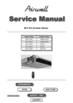
1
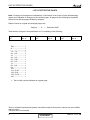
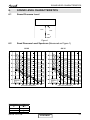
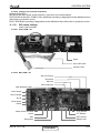
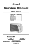
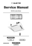
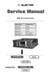
CK DC Inverter Series
Indoor Units
Outdoor Units
CK 25 DCI
DCI 25
CK 35 DCI
DCI 35
CK 50 DCI
DCI 50
CK 60 DCI
DCI 60
CK 70 DCI
DCI 72Z
REFRIGERANT
R410A
HEAT PUMP
SM CK 1-A.1 GB
AUGUST – 2008
CONTENT
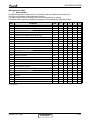
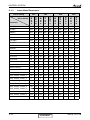
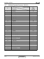
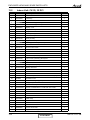
LIST OF EFFECTIVE PAGES
LIST OF EFFECTIVE PAGES
Note: Changes in the pages are indicated by a “Revision#” in the footer of each effected page
(when none indicates no changes in the relevant page). All pages in the following list represent
effected/ non effected pages divided by chapters.
Dates of issue for original and changed pages are:
Original ....... 0 ........ December 2007
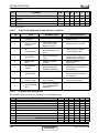
Total number of pages in this publication is 111 consisting of the following:
Page
No.
Revision
No. #
Page
No.
Revision
No. #
Page
No.
Revision
No. #
Title .......................1
A ...........................1
i .............................1
1-1 - 1-3 ................1
2-1 - 2-6 ................1
3-1 ........................1
4-1 - 4-3 ................1
5-1 - 5-21 ..............1
6-1 - 6-5 ................1
7-1 ........................1
8-1 - 8-2 ................1
9-1 ........................1
10-1 ......................1
11-1-11-26.............1
12-1-12-8 ..............1
13-1-13-15 ............1
14-1 ......................1
•
Zero in this column indicates an original page.
*Due to constant improvements please note that the data on this service manual can be modified
with out notice.
**Photos are not contractual
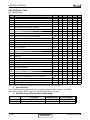
A
CONTENT
SM CK 1- A.1 GB
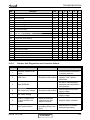
TABLE OF CONTENTS
Table of Contents
1.
INTRODUCTION ...................................................................................................1-1
2.
PRODUCT DATA SHEET ......................................................................................2-1
3.
RATING CONDITIONS ..........................................................................................3-1
4.
OUTLINE DIMENSIONS .......................................................................................4-1
5.
PERFORMANCE DATA & PRESSURE CURVES ...............................................5-1
6.
SOUND LEVEL CHARACTERISTICS ..................................................................6-1
7.
ELECTRICAL DATA ..............................................................................................7-1
8.
WIRING DIAGRAMS .............................................................................................8-1
9.
REFRIGERATION DIAGRAMS .............................................................................9-1
10. TUBING CONNECTIONS......................................................................................10-1
11.
CONTROL SYSTEM .............................................................................................11-1
12. TROUBLESHOOTING ..........................................................................................12-1
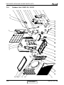
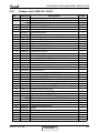
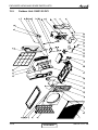
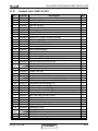
13. EXPLODED VIEWS AND SPARE PARTS LISTS .................................................13-1
14. APPENDIX A .........................................................................................................14-1
SM CK 1-A.1 GB
i
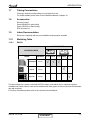
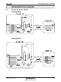
INTRODUCTION
1.
INTRODUCTION
1.1
General
The CK DCI Inverter Cassette type split air conditioner range comprise RC (heat pump)
models, as follows:
●
●
●
●
●
1.2
CK 25
CK 35
CK 50
CK 60
CK 70
Main Features
The CK DCI series benefits from the most advanced technological innovations,
namely:
● DC inverter technology.
● R410A refrigerant.
● High COP.
● Precharged refrigerant.
● Low Sound level for both Indoor and Outdoor.
● 60 x60 cm dimension designed for integration in suspended ceilings.
● DC Brushless fan motor.
● New grille, modern style with elegant lines in line with every interior decor , 2 panels
optional available (hard ceiling / Suspended ceiling).
● Motorized air distribution flaps.
● Very slim profile 219 mm at size 9-12, and 270 mm at size 18-24.
● Option of fresh air intake, and air distribution to adjacent room.
● Integrated condensate pump with a lift of 1 m Max.
● Connection to Multisplit outdoor units.
● Up to 30 m pipe length between indoor and outdoor units.
● Up to 15 m vertical high between indoor and outdoor units.
● Cooling operation at outdoor temperature down to -10°C.
● Heating operation at outdoor temperature down to -15°C.
● Built in over-flow protection against the condensate water.
● Easy installation and service.
● Product can have the option of additional function of Ionizer and ESF.
● Fan speed can be adjusted by compensation on PCB according to different installation
height (Field option).
SM CK 1-A.1 GB
CONTENT
1-1
INTRODUCTION
1.3
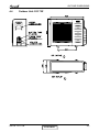
Indoor Unit
The indoor unit is cassette type indoor unit, and can be easily fitted to many types of
residential and commercials applications.
It includes:
● Coil with hydrophilic aluminum fins.
● Motorized flaps (two step motors).
● Advanced electronic control box assembly (DCI storm).
● Low sound level of the indoor fan.
1.4
Filtration
The CK series presents several types of air filters:
● Easily accessible, and re-usable pre-filters.
● Easily Static Filter (Field Option).
1.5
Control
The microprocessor indoor controller, and an infrared remote control, supplied as
standard, providing complete operating function and programming. For further details
please refer to the Operation Manual, Appendix A.
1.6
Outdoor Unit
The CK outdoor units can be installed as floor or wall mounted units by using a wall
supporting bracket. The metal sheets are protected by anti- corrosion paint work allowing
long life resistance. All outdoor units are pre-charged. For further information please
refer to the Product Data Sheet, Chapter 2.
It includes:
● Compressor mounted in a soundproofed compartment:
Single Rotary – for DCI 25 and DCI 35.
Scroll – for DCI 50 and DCI 60.
Twin Rotary – for DCI 72Z.
● Axial fan.
● Outdoor coil with hydrophilic louver fins for RC units.
● Outlet air fan grill.
● Service valves” flare” type connection.
● Interconnecting wiring terminal block.
1-2
CONTENT
SM CK 1-A.1 GB
INTRODUCTION
1.7
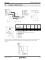
Tubing Connections
Flare type interconnecting tubing to be produced on site.
For further details please refer to the Installation Manual, Chapter 10.
1.8
Accessories
Remote Control.
Panel 625x625 for gird ceiling.
Panel 725x725 for hard ceiling.
ESF & Ionizer kit.
1.9
Inbox Documentation
Each unit is supplied with its own installation and operation manuals.
1.10
Matching Table
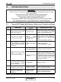
1.10.1
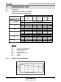
R410A
INDOOR UNITS
OUTDOOR UNITS
MODEL
REFRIGER.
CK 25
DCI25/35/50
R410A
√
DCI 60
R410A
DCI 72Z
R410A
CK 35
CK 50
CK 60
CK 70
√ √
√
√
The above table lists outdoor units and PXD DCI indoor units which can be matched together.
In addition the listed outdoor units can be matched with other types of indoor units such as cassettes
and wall mounted.
For further information please refer to the relevant Service Manual.
SM CK 1-A.1 GB
CONTENT
1-3
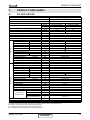
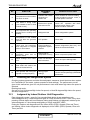
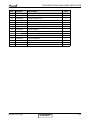
PRODUCT DATA SHEET
2.
PRODUCT DATA SHEET
2.1
CK 25 DCI R410A
CK25 DCI
DCI 25 R410A
Model Indoor Unit
Model Outdoor Unit
Installation Method of Pipe
Characteristics
Capacity (4)
Power input (4)
EER (Cooling) or COP(Heating) (4)
Energy efficiency class
Power supply
Rated current
Starting current
Circuit breaker rating
Fan type & quantity
Fan speeds
H/M/L
H/M/L
Air flow (1)
External static pressure
Min-Max
H/M/L
Sound power level (2)
(3)
H/M/L
Sound pressure level
Moisture removal
Condensate drain tube I.D
Dimensions
WxHxD
Weight
Package dimensions
WxHxD
Packaged weight
Units per pallet
Stacking height
Refrigerant control
Compressor type, model
Fan type & quantity
Fan speeds
H/L
Air flow
H/L
Sound power level
H/L
H/L
Sound pressure level (3)
Dimensions
WxHxD
Weight
Package dimensions
WxHxD
Packaged weight
Units per pallet
Stacking height
Refrigerant type
Refrigerant chargless distance
Additional charge
Liquid line
Suction line
Connections
Max.tubing length
between units
Max.10
kW
Remote control
NA
INDOOR
RPM
m3/hr
Pa
dB(A)
dB(A)
l/hr
mm
mm
kg
mm
kg
units
units
RPM
m3/hr
dB(A)
dB(A)
mm
kg
mm
kg
Units
units
OUTDOOR
(1)
(2)
(3)
(4)
m.
V/Ph/Hz
A
A
A
Max.height difference
Operation control type
Heating elements
kg/m
g/m
In.(mm)
In.(mm)
m.
Flared
Cooling
Heating
8550(5100-12300)
10900(5100-16400)
2.5(1.5-3.6)
3.2(1.5-4.8)
0.59(0.45-1.00)
0.8(0.50-1.40)
4.24
4.00
A
A
220-240V/Single/50Hz
2.6
3.6
10.5
15
Centrifugal x 1
550/450/350
600/500/400
440
460
0
49
49
32/26
32/26
0.7
20
575X575X219
13(2.2/2.8)
681X681X297
15
12
6 levels
Electronical Expansion Valve
Single Rotary DC Inverter, Panasonic 5RS102XAB
Propeller x 1
830
1780
60
61
50
51
795*290*610
38
945*395*655
42
9
3 levels
R410A
1.1kg/7.5m
No need
1/4"(6.35)
3/8"(9.53)
Max.25
Units
Btu/hr
kW
kW
W/W
Rating conditions in accordance with ISO 5151 and ISO 13253 (for ducted units) and EN 14511.
Airflow in ducted units; at nominal external static pressure.
Sound power in ducted units is measured at air discharge.
Sound pressure level measured at 1 meter distance from unit.
SM CK 1-A.1 GB
CONTENT
2-1
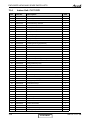
PRODUCT DATA SHEET
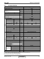
2.2
CK 35 DCI R410A
CK35 DCI
DCI 35 R410A
Model Indoor Unit
Model Outdoor Unit
Installation Method of Pipe
Characteristics
Capacity (4)
OUTDOOR
INDOOR
Power input (4)
EER (Cooling) or COP(Heating) (4)
Energy efficiency class
Power supply
Rated current
Starting current
Circuit breaker rating
Fan type & quantity
Fan speeds
H/M/L
(1)
H/M/L
Air flow
External static pressure
Min-Max
H/M/L
Sound power level (2)
H/M/L
Sound pressure level (3)
Moisture removal
Condensate drain tube I.D
Dimensions
WxHxD
Weight
Package dimensions
WxHxD
Packaged weight
Units per pallet
Stacking height
Refrigerant control
Compressor type, model
Fan type & quantity
Fan speeds
H/L
Air flow
H/L
Sound power level
H/L
H/L
Sound pressure level (3)
Dimensions
WxHxD
Weight
Package dimensions
WxHxD
Packaged weight
Units per pallet
Stacking height
Refrigerant type
Refrigerant chargless distance
Additional charge
Liquid line
Suction line
Connections
between units
Max.tubing length
Max.height difference
Operation control type
Heating elements
(1)
(2)
(3)
(4)
Units
Btu/hr
kW
kW
W/W
V/Ph/Hz
A
A
A
RPM
m3/hr
Pa
dB(A)
dB(A)
l/hr
mm
mm
kg
mm
kg
units
units
RPM
m3/hr
dB(A)
dB(A)
mm
kg
mm
kg
Units
units
kg/m
g/m
In.(mm)
In.(mm)
m.
m.
kW
Flared
Cooling
Heating
11950(5800-14700)
14350(5450-18800)
3.5(1.7-4.3)
4.2(1.6-5.5)
0.96(0.50-1.30)
1.16(0.59-1.70)
3.63
3.64
A
A
220-240V/Single/50Hz
4.3
5.2
10.5
15
Centrifugal x 1
600/500/400
650/550/450
490
520
0
51
51
34/28
34/28
1.38
20
575X575X219
13
681X681X297
15
12
6 levels
Electronical Expansion Valve
Single Rotary DC Inverter, Panasonic 5RS102XAB
Propeller x 1
830
1780
62
62
52
52
795*290*610
38.5
945*395*655
42.5
9
3 levels
R410A
1.2kg/7.5m
No need
1/4"(6.35)
3/8"(9.53)
Max.25
Max.10
Remote control
NA
Rating conditions in accordance with ISO 5151 and ISO 13253 (for ducted units) and EN 14511.
Airflow in ducted units; at nominal external static pressure.
Sound power in ducted units is measured at air discharge.
Sound pressure level measured at 1 meter distance from unit.
2-2
CONTENT
SM CK 1-A.1 GB
PRODUCT DATA SHEET
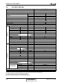
2.3
CK 50 DCI R410A
CK-50 DCI
DCI 50 R410A
Model Indoor Unit
Model Outdoor Unit
Installation Method of Pipe
Characteristics
Power input (4)
EER (Cooling) or COP(Heating) (4)
Energy efficiency class
Power supply
Rated current
Starting current
Circuit breaker rating
Fan type & quantity
Fan speeds
Air flow (1)
H/M/L
H/M/L
RPM
m3/hr
Flared
Cooling
Heating
17050(4450-20500)
19100(4450-23900)
5.0(1.3-6.0)
5.6(1.3-7.0)
1.56(0.46-2.11)
1.55(0.36-2.50)
3.22
3.62
A
A
220-240V/Single/50Hz
7.0
7.2
10.5
20
Centrifugal x 1
750/650/550
750/650/550
700
700
External static pressure
Min-Max
Pa
0
H/M/L
dB(A)
53
53
H/M/L
dB(A)
38/30
38/30
Units
Btu/hr
kW
kW
W/W
Capacity (4)
INDOOR
Sound power level
(2)
Sound pressure level
(3)
Moisture removal
Condenstate drain tube I.D
Dimensions
Weight
Package dimensions
Packaged weight
Units per pallet
Stacking height
Refrigerant control
Compressor type,model
Fan type & quantity
Fan speeds
Air flow
Sound power level
Sound pressure level (3)
V/Ph/Hz
A
A
A
WxHxD
WxHxD
H/L
H/L
H/L
RPM
m3/hr
dB(A)
H/L
dB(A)
OUTDOOR
Dimensions
WxHxD
Weight
Package dimensions
WxHxD
Packaged weight
Units per pallet
Stacking height
Refrigerant type
Refrigerant chargless distance
Additional charge
Liquid line
Suction line
Connections
between units Max.tubing length
Max.height difference
Operation control type
Heating elements
(1)
(2)
(3)
(4)
l/hr
mm
mm
kg
mm
kg
units
units
2.07
20
575*575*270
???
575X575X270
15.2
681X681X348
17.7
Electronical Expansion Valve
Single Rotary DC Inverter,Panasonic 5RS130XCC03
Propeller x 1
920
2160
62
63
mm
kg
mm
kg
Units
units
kg/m
g/m
In.(mm)
In.(mm)
m.
m.
52
53
795*290*610
39
945*395*655
43
9
3 levels
R410A
1.5kg/7.5m
No need
1/4"(6.35)
1/2"(12.7)
Max.30
Max.10
Remote control
kW
Rating conditions in accordance with ISO 5151 and ISO 13253 (for ducted units) and EN 14511.
Airflow in ducted units; at nominal external static pressure.
Sound power in ducted units is measured at air discharge.
Sound pressure level measured at 1 meter distance from unit.
SM CK 1-A.1 GB
CONTENT
2-3
PRODUCT DATA SHEET
2.4
CK 60 DCI R410A
CK 60 DCI
DCI 60 R410A
Model Indoor Unit
Model Outdoor Unit
Installation Method of Pipe
Characteristics
Capacity (4)
OUTDOOR
INDOOR
Power input (4)
EER (Cooling) or COP(Heating) (4)
Energy efficiency class
Power supply
Rated current
Starting current
Circuit breaker rating
Fan type & quantity
Fan speeds
H/M/L
(1)
H/M/L
Air flow
External static pressure
Min-Max
H/M/L
Sound power level (2)
H/M/L
Sound pressure level (3)
Moisture removal
Condenstate drain tube I.D
Dimensions
WxHxD
Weight
Package dimensions
WxHxD
Packaged weight
Units per pallet
Stacking height
Refrigerant control
Compressor type,model
Fan type & quantity
Fan speeds
H/L
Air flow
H/L
Sound power level
H/L
H/L
Sound pressure level (3)
Dimensions
WxHxD
Weight
Package dimensions
WxHxD
Packaged weight
Units per pallet
Stacking height
Refrigerant type
Refrigerant chargless distance
Additional charge per 1 meter
Liquid line
Suction line
Connections
between units
Max.tubing length
Max.height difference
Operation control type
Heating elements (Option)
(1)
(2)
(3)
(4)
Units
Btu/hr
kW
kW
W/W
V/Ph/Hz
A
A
A
RPM
m3/hr
Pa
dB(A)
dB(A)
l/hr
mm
mm
kg
mm
kg
units
units
RPM
m3/hr
dB(A)
dB(A)
mm
kg
mm
kg
Units
units
kg/m
g/m
In.(mm)
In.(mm)
m.
m.
Flared
Cooling
Heating
19800(4800~22200)
23200(6800~27300)
5.8(1.4-6.5)
6.8(2.0~8.0)
1.92(0.44-2.20)
2.11(0.52~2.60)
3.02
3.22
B
C
220-240V/Single/50Hz
8.6
9.5
15
20
Centrifugal x 1
800/7100/600
800/700/600
800
800
0
58
58
41/33
41/33
2.62
20
575X575X270
15.2
681X681X348
17.7
12
6 levels
EEV
E-Scroll MATSUSHITA 5CS130XCC03
Propeller(direct) x 1
820
2860
65
55
846x690x302
46
990x770x430
50
9
3 levels
R410A
1.65kg/7.5m
No Need
1/4"(6.35)
1/2"(12.7)
Max.30
Max.15
Remote control
kW
Rating conditions in accordance with ISO 5151 and ISO 13253 (for ducted units) and EN 14511.
Airflow in ducted units; at nominal external static pressure.
Sound power in ducted units is measured at air discharge.
Sound pressure level measured at 1 meter distance from unit.
2-4
CONTENT
SM CK 1-A.1 GB
PRODUCT DATA SHEET
2.5
CK 72(Z) DCI R410A
CK70 DCI
DCI 72Z R410A
Model Indoor Unit
Model Outdoor Unit
Installation Method of Pipe
Characteristics
Capacity (4)
OUTDOOR
INDOOR
Power input (4)
EER (Cooling) or COP(Heating) (4)
Energy efficiency class
Power supply
Rated current
Starting current
Circuit breaker rating
Fan type & quantity
Fan speeds
H/M/L
(1)
H/M/L
Air flow
External static pressure
Min-Max
H/M/L
Sound power level (2)
H/M/L
Sound pressure level (3)
Moisture removal
Condenstate drain tube I.D
Dimensions
WxDxH
Weight(
Package dimensions
WxDxH
Packaged weight
Units per pallet
Stacking height
Refrigerant control
Compressor type,model
Fan type & quantity
Fan speeds
H/L
Air flow
H/L
Sound power level
H/L
H/L
Sound pressure level (3)
Dimensions
WxHxD
Weight
Package dimensions
WxHxD
Packaged weight
Units per pallet
Stacking height
Refrigerant type
Refrigerant chargless distance
Additional charge per 1 meter
Liquid line
Suction line
Connections
between units Max.tubing length
Max.height difference
Operation control type
Heating elements (Option)
(1)
(2)
(3)
(4)
Units
Btu/hr
kW
kW
W/W
V/Ph/Hz
A
A
A
RPM
m3/hr
Pa
dB(A)
dB(A)
l/hr
mm
mm
kg
mm
kg
units
units
RPM
m3/hr
dB(A)
dB(A)
mm
kg
mm
kg
Units
units
kg/m
g/m
In.(mm)
In.(mm)
m.
m.
Flared
Cooling
Heating
23200(5110~25570)
24890(5110~28640)
6.8(1.5-8.0)
7.3(1.5~9.0)
2.41(0.5-2.65)
2.27(0.5~2.92)
2.82
3.22
C
C
220-240V/Single/50Hz
10.8
10.2
15
20
Centifugal x 1
850/750/650
850/750/650
830
830
0
60
60
43/35
43/35
2.66
20
575X575X270
15.5
681X681X348
18
12
6 levels
EEV
Two Rotary,Mitsubishi TNB220F
Propeller(direct) x 1
850
3350
65
55
950x412x835
65
1080x477x910
70
9
3 levels
R410A
2.045kg/7.5m
No Need
3/8"(9.53)
5/8"(15.88)
Max.30
Max.15
Remote control
kW
Rating conditions in accordance with ISO 5151 and ISO 13253 (for ducted units) and EN 14511.
Airflow in ducted units; at nominal external static pressure.
Sound power in ducted units is measured at air discharge.
Sound pressure level measured at 1 meter distance from unit.
SM CK 1-A.1 GB
CONTENT
2-5
PRODUCT DATA SHEET
2.6
Optional accessory
Panel 625x625(Optional accessory)
Dimensions (H x L x D)
Weight
Package Dimensions (H x L x D)
For all the models
mm
625x625x40
kg
2.2
mm
700x700x103
Package Weight
kg
3.4
Units per pallet
units
20
Stacking height
units
10 levels
Panel 725x725(Optional accessory)
Dimensions (H x L x D)
Weight
Package Dimensions (H x L x D)
For all the models
mm
725x725x40
kg
2.7
mm
800x800x103
Package Weight
kg
4.2
Units per pallet
units
10
Stacking height
units
10 levels
2-6
CONTENT
SM CK 1-A.1 GB
RATING CONDITIONS
3.
RATING CONDITIONS
Standard conditions in accordance with ISO 5151, ISO 13253 (for ducted units)
and EN 14511.
Cooling:
Indoor:
27oC DB 19oC WB
Outdoor: 35 oC DB
Heating:
Indoor:
20oC DB
Outdoor: 7oC DB 6oC WB
3.1
Operating Limits
R410A DCI (Excluding Delta Units)
Indoor
Cooling
Heating
Voltage
SM CK 1-A.1 GB
Outdoor
Upper limit
32oC DB 23oC WB
46oC DB
Lower limit
21oC DB 15oC WB
-10oC DB
Upper limit
27oC DB
24oC DB 18oC WB
Lower limit
10oC DB
-15oC DB -16oC WB
1PH
198 – 264 V
3PH
N/A
CONTENT
3-1
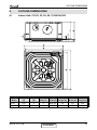
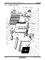
OUTLINE DIMENSIONS
4.
OUTLINE DIMENSIONS
4.1
Indoor Unit: CK 25, 35, 50, 60, 70 R410A DCI
Unit
Model
Main unit
(A)
Insulation
(B)
Front
Step (C)
Front
width (D)
Front
height (E)
Unit Body
Width (W)
Effective
Height (H)
25/35
219
2
9
625/725
40
575
230
50/60/70
270
2
9
625/725
40
575
281
SM CK 1-A.1 GB
CONTENT
4-1
OUTLINE DIMENSIONS
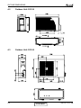
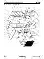
4.2
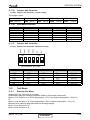
Outdoor Unit: DCI 50
4.3
Outdoor Unit: DCI 60
4-2
CONTENT
SM CK 1-A.1 GB
OUTLINE DIMENSIONS
4.4
Outdoor Unit: DCI 72Z
SM CK 1-A.1 GB
CONTENT
4-3
PERFORMANCE DATA & PRESSURE CURVES
5.
PERFORMANCE DATA
5,1
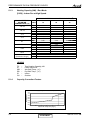
CK 25 DCI
5.1.1
Cooling Capacity (kW) – Run Mode
[230V] : Indoor Fan at High Speed.
ID COIL ENTERING AIR DB/WB TEMPERATURE [C0]
OD COIL
ENTERING AIR DB
TEMPERATURE [0C]
DATA
TC
SC
PI
TC
SC
PI
TC
SC
PI
TC
SC
PI
TC
SC
PI
TC
SC
PI
-10 - 20
(protection range)
25
30
35
40
46
22/15
24/17
27/19
29/21
32/23
2.42
1.72
0.46
2.30
1.67
0.52
2.18
1.63
0.57
2.07
1.59
0.63
1.93
1.53
0.69
80 - 110 % of nominal
80 - 105 % of nominal
25 - 50 % of nominal
2.57
2.73
2.89
1.75
1.79
1.82
0.47
0.48
0.49
2.46
2.62
2.77
1.71
1.74
1.78
0.54
0.53
0.54
2.34
2.66
2.50
1.66
1.70
1.74
0.59
0.58
0.60
2.23
2.54
2.38
1.62
1.66
1.69
0.64
0.64
0.65
2.09
2.24
2.40
1.57
1.60
1.64
0.70
0.71
0.72
3.05
1.86
0.50
2.93
1.81
0.55
2.82
1.77
0.61
2.70
1.73
0.66
2.56
1.67
0.73
LEGEND
TC
SC
PI
WB
DB
ID
OU
5.1.2
–
–
–
–
–
–
–
Total Cooling Capacity, kW
Sensible Capacity, kW
Power Input, kW
Wet Bulb Temp., (oC)
Dry Bulb Temp., (oC)
Indoor
Outdoor
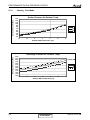
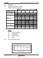
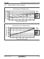
Capacity Correction Factors
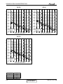
Cooling Capacity Ratio Vs. Outdoor Temperature
1.20
Capacity Ratio
1.10
1.00
0.90
0.80
0.70
0.60
0.50
20
25
30
35
40
45
Outdoor Temperature [ºC]
SM CK 1-A.1 GB
CONTENT
5-1
PERFORMANCE DATA & PRESSURE CURVES
5.1.3
Heating Capacity (kW) - Run Mode
[230V] : Indoor Fan at High Speed.
ID COIL ENTERING AIR DB TEMPERATURE [C0]
OD COIL ENTERING
AIR DB/WB
TEMPERATURE [0C]
-15/-16
-10/-12
-7/-8
-1/-2
2/1
7/6
10/9
15/12
15-24
(Protection Range)
DATA
15
20
25
TC
PI
TC
PI
TC
PI
TC
PI
TC
PI
TC
PI
TC
PI
TC
PI
TC
PI
2.04
0.48
2.27
0.58
2.44
0.65
2.53
0.69
2.58
0.71
3.34
0.75
3.53
0.80
3.71
0.84
1.89
0.53
2.12
0.63
2.30
0.70
2.38
0.74
2.44
0.76
3.20
0.80
3.38
0.84
3.57
0.89
85 - 105 % of nominal
80 - 120 % of nominal
1.75
0.58
1.98
0.68
2.16
0.75
2.24
0.79
2.30
0.81
3.06
0.85
3.24
0.89
3.43
0.94
LEGEND
TC
PI
WB
DB
ID
OU
5.1.4
–
–
–
–
–
–
Total Heating Capacity, kW
Power Input, kW
Wet Bulb Temp., (oC)
Dry Bulb Temp., (oC)
Indoor
Outdoor
Capacity Correction Factors
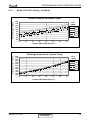
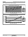
Heating Capacity Ratio Vs. Outdoor Temperature
1.20
Capacity Ration
1.10
1.00
0.90
0.80
0.70
0.60
0.50
-15
-10
-5
0
5
10
15
Outdoor WB Temperature [deg C]
5-2
CONTENT
SM CK 1-A.1 GB
PERFORMANCE DATA & PRESSURE CURVES
5.1.5
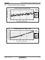
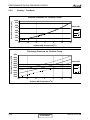
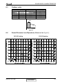
Model: CK 25 DCI Cooling - Test Mode
Suction Pressure Vs.Outdoor Temp.
Suction Pressure [kPa]
1400
Indoor
DB/WB
1300
1200
1100
22/15
1000
24/17
900
27/19
800
29/21
700
32/23
600
500
10
15
20
25
30
35
40
45
Outdoor DB Temperature[ºC ]
Discharge Pressure [kPa]
Discharge Pressure Vs. Outdoor Temp.
4000
3750
3500
3250
3000
2750
2500
2250
2000
1750
1500
1250
1000
Indoor
DB/WB
22/15
24/17
27/19
29/21
32/23
10
15
20
25
30
35
40
45
Outdoor DB Temperature[ºC ]
SM CK 1-A.1 GB
CONTENT
5-3
PERFORMANCE DATA & PRESSURE CURVES
5.1.6
Heating - Test Mode
Suction Pressure [kPa]
Suction Pressure Vs.Outdoor Temp.
1300
1200
1100
1000
900
800
700
600
500
400
300
200
-15
15
20
25
-10
-5
0
5
10
15
Outdoor WB Temperature [ºC]
Discharge Pressure [kPa]
Discharge Pressure Vs. Outdoor Temp.
4000
3750
3500
3250
3000
2750
2500
2250
2000
1750
1500
1250
1000
-15
Indoor DB
15
20
25
-10
-5
0
5
10
15
Outdoor WB Temperature [ºC]
5-4
CONTENT
SM CK 1-A.1 GB
PERFORMANCE DATA & PRESSURE CURVES
5.2
CK 35 DCI
5.2.1
Cooling Capacity (kW) - Run Mode
[230V] : Indoor Fan at High Speed.
ID COIL ENTERING AIR DB/WB TEMPERATURE [C0]
OD COIL
ENTERING AIR DB
TEMPERATURE [0C]
DATA
TC
SC
PI
TC
SC
PI
TC
SC
PI
TC
SC
PI
TC
SC
PI
TC
SC
PI
-10 - 20
(protection range)
25
30
35
40
46
22/15
24/17
27/19
29/21
32/23
3.38
2.40
0.75
3.22
2.34
0.84
3.06
2.28
0.93
2.89
2.22
1.02
2.70
2.15
1.13
80 - 110 % of nominal
80 - 105 % of nominal
25 - 50 % of nominal
3.60
3.83
4.05
2.45
2.50
2.55
0.77
0.78
0.80
3.44
3.66
3.88
2.39
2.44
2.49
0.87
0.86
0.89
3.28
3.72
3.50
2.33
2.38
2.43
0.96
0.95
0.97
3.12
3.56
3.34
2.27
2.32
2.37
1.03
1.05
1.06
2.92
3.14
3.36
2.20
2.25
2.30
1.14
1.15
1.17
4.27
2.60
0.81
4.11
2.54
0.90
3.94
2.48
0.99
3.78
2.42
1.08
3.58
2.34
1.18
LEGEND
TC
SC
PI
WB
DB
ID
OU
5.2.2
–
–
–
–
–
–
–
Total Cooling Capacity, kW
Sensible Capacity, kW
Power Input, kW
Wet Bulb Temp., (oC)
Dry Bulb Temp., (oC)
Indoor
Outdoor
Capacity Correction Factor
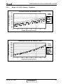
Cooling Capacity Ratio Vs. Outdoor Temperature
1.20
Capacity Ratio
1.10
1.00
0.90
0.80
0.70
0.60
0.50
20
25
30
35
40
45
Outdoor Temperature [ºC]
SM CK 1-A.1 GB
CONTENT
5-5
PERFORMANCE DATA & PRESSURE CURVES
5.2.3
Heating Capacity (kW) - Run Mode
[230V] : Indoor Fan at High Speed.
ID COIL ENTERING AIR DB TEMPERATURE [C0]
OD COIL ENTERING
AIR DB/WB
TEMPERATURE [0C]
-15/-16
-10/-12
-7/-8
-1/-2
2/1
7/6
10/9
15/12
15-24
(Protection Range)
DATA
15
20
25
TC
PI
TC
PI
TC
PI
TC
PI
TC
PI
TC
PI
TC
PI
TC
PI
TC
PI
2.67
0.70
2.98
0.84
3.20
0.95
3.32
1.00
3.39
1.04
4.39
1.09
4.63
1.15
4.87
1.22
2.49
0.77
2.79
0.91
3.02
1.02
3.13
1.07
3.20
1.11
4.20
1.16
4.44
1.23
4.68
1.29
85 - 105 % of nominal
80 - 120 % of nominal
2.30
0.84
2.60
0.98
2.83
1.09
2.94
1.14
3.02
1.18
4.01
1.23
4.26
1.30
4.50
1.36
LEGEND
TC
PI
WB
DB
ID
OU
5.2.4
–
–
–
–
–
–
Total Heating Capacity, kW
Power Input, kW
Wet Bulb Temp., (oC)
Dry Bulb Temp., (oC)
Indoor
Outdoor
Capacity Correction Factors
Heating Capacity Ratio Vs. Outdoor Temperature
1.20
Capacity Ration
1.10
1.00
0.90
0.80
0.70
0.60
0.50
-15
-10
-5
0
5
10
15
Outdoor WB Temperature [deg C]
5-6
CONTENT
SM CK 1-A.1 GB
PERFORMANCE DATA & PRESSURE CURVES
5.2.5
Model: CK 35 DCI Cooling - Test Mode
Suction Pressure VS.Outdoor Temp.
Suction Pressure [kPa]
1400
Indoor
DB/WB
1300
22/15
1200
24/17
1100
27/19
1000
29/21
900
32/23
800
700
600
500
10
15
20
25
30
35
40
45
Outdoor DB Temperature[ºC ]
Discharge Pressure [kPa]
Discharge Pressure VS. Outdoor Temp.
4000
3750
3500
3250
3000
2750
2500
2250
2000
1750
1500
1250
1000
Indoor
DB/WB
22/15
24/17
27/19
29/21
32/23
10
15
20
25
30
35
40
45
Outdoor DB Temperature[ºC ]
SM CK 1-A.1 GB
CONTENT
5-7
PERFORMANCE DATA & PRESSURE CURVES
5.2.6
Heating - Test Mode
Suction Pressure VS.Outdoor Temp.
1300
Suction Pressure [kPa]
1200
1100
1000
900
800
15
700
20
600
25
500
400
300
200
-15
-10
-5
0
5
10
15
Outdoor WB Temperature [ºC]
Discharge Pressure [kPa]
Discharge Pressure VS. Outdoor Temp.
4000
3750
3500
3250
3000
2750
Indoor DB
15
2500
2250
2000
1750
1500
1250
1000
-15
20
25
-10
-5
0
5
10
15
Outdoor WB Temperature [ºC]
5-8
CONTENT
SM CK 1-A.1 GB
PERFORMANCE DATA & PRESSURE CURVES
5.3
CK 50 DCI
5.3.1
Cooling Capacity (kW) - Run Mode
[230V] : Indoor Fan at High Speed.
ID COIL ENTERING AIR DB/WB TEMPERATURE [C0]
OD COIL
ENTERING AIR DB
TEMPERATURE [0C]
DATA
TC
SC
PI
TC
SC
PI
TC
SC
PI
TC
SC
PI
TC
SC
PI
TC
SC
PI
-10 - 20
(protection range)
25
30
35
40
46
22/15
24/17
27/19
29/21
32/23
4.83
3.43
1.23
4.60
3.35
1.37
4.37
3.26
1.51
4.14
3.17
1.66
3.86
3.07
1.83
80 - 110 % of nominal
80 - 105 % of nominal
25 - 50 % of nominal
5.15
5.47
5.78
3.50
3.57
3.64
1.25
1.27
1.30
4.92
5.23
5.55
3.42
3.49
3.56
1.42
1.39
1.44
4.68
5.32
5.00
3.33
3.40
3.47
1.56
1.54
1.58
4.45
5.08
4.77
3.24
3.31
3.38
1.68
1.70
1.73
4.17
4.49
4.80
3.14
3.21
3.28
1.85
1.88
1.90
6.10
3.71
1.32
5.86
3.63
1.46
5.63
3.54
1.61
5.40
3.45
1.75
5.12
3.35
1.92
LEGEND
TC
SC
PI
WB
DB
ID
OU
5.3.2
–
–
–
–
–
–
–
Total Cooling Capacity, kW
Sensible Capacity, kW
Power Input, kW
Wet Bulb Temp., (oC)
Dry Bulb Temp., (oC)
Indoor
Outdoor
Capacity Correction Factors
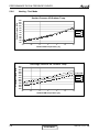
Cooling Capacity Ratio Vs. Outdoor Temperature
1.20
Capacity Ratio
1.10
1.00
0.90
0.80
0.70
0.60
0.50
20
25
30
35
40
45
Outdoor Temperature [ºC]
SM CK 1-A.1 GB
CONTENT
5-9
PERFORMANCE DATA & PRESSURE CURVES
5.3.3
Heating Capacity (kW) - Run Mode
[230V] : Indoor Fan at High Speed.
ID COIL ENTERING AIR DB TEMPERATURE [C0]
OD COIL ENTERING
AIR DB/WB
TEMPERATURE [0C]
-15/-16
-10/-12
-7/-8
-1/-2
2/1
7/6
10/9
15/12
15-24
(Protection Range)
DATA
15
20
25
TC
PI
TC
PI
TC
PI
TC
PI
TC
PI
TC
PI
TC
PI
TC
PI
TC
PI
3.69
0.96
4.11
1.16
4.42
1.31
4.58
1.38
4.68
1.43
6.06
1.50
6.39
1.59
6.73
1.68
3.43
1.06
3.85
1.26
4.16
1.40
4.32
1.48
4.43
1.53
5.80
1.60
6.13
1.69
6.47
1.78
85 - 105 % of nominal
80 - 120 % of nominal
3.18
1.16
3.59
1.35
3.91
1.50
4.06
1.57
4.17
1.62
5.54
1.70
5.88
1.79
6.21
1.88
LEGEND
TC
PI
WB
DB
ID
OU
5.3.4
–
–
–
–
–
–
Total Heating Capacity, kW
Power Input, kW
Wet Bulb Temp., (oC)
Dry Bulb Temp., (oC)
Indoor
Outdoor
Capacity Correction Factors
Heating Capacity Ratio Vs. Outdoor Temperature
1.20
Capacity Ration
1.10
1.00
0.90
0.80
0.70
0.60
0.50
-15
-10
-5
0
5
10
15
Outdoor WB Temperature [deg C]
5-10
CONTENT
SM CK 1-A.1 GB
PERFORMANCE DATA & PRESSURE CURVES
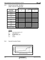
5.3.5
Model: CK 50 DCI Cooling - Test Mode
Suction Pressure VS.Outdoor Temp.
Suction Pressure [kPa]
1400
Indoor
DB/WB
1300
1200
1100
22/15
1000
24/17
27/19
900
29/21
800
32/23
700
600
500
10
15
20
25
30
35
40
45
Outdoor DB Temperature[ºC ]
Discharge Pressure [kPa]
Discharge Pressure VS. Outdoor Temp.
4250
4000
3750
3500
3250
3000
2750
2500
2250
2000
1750
1500
1250
1000
Indoor
DB/WB
22/15
24/17
27/19
29/21
32/23
10
15
20
25
30
35
40
45
Outdoor DB Temperature[ºC ]
SM CK 1-A.1 GB
CONTENT
5-11
PERFORMANCE DATA & PRESSURE CURVES
5.3.6
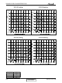
Heating - Test Mode
Suction Pressure VS.Outdoor Temp.
Suction Pressure [kPa]
1100
1000
900
15
800
20
700
25
600
500
400
300
200
-15
-10
-5
0
5
10
15
Outdoor WB Temperature [ºC]
Discharge Pressure [kPa]
Discharge Pressure VS. Outdoor Temp.
4000
3750
3500
3250
3000
2750
2500
2250
2000
1750
1500
1250
1000
-15
Indoor DB
15
20
25
-10
-5
0
5
10
15
Outdoor WB Temperature [ºC]
5-12
CONTENT
SM CK 1-A.1 GB
PERFORMANCE DATA & PRESSURE CURVES
5.4
CK 60 DCI
5.4.1
Cooling Capacity (kW) - Run Mode
[230V] : Indoor Fan at High Speed.
ID COIL ENTERING AIR DB/WB TEMPERATURE [C0]
OD COIL
ENTERING AIR DB
TEMPERATURE [0C]
DATA
TC
SC
PI
TC
SC
PI
TC
SC
PI
TC
SC
PI
TC
SC
PI
TC
SC
PI
-10 - 20
(protection range)
25
30
35
40
46
22/15
24/17
27/19
29/21
32/23
5.61
3.98
1.51
5.34
3.88
1.69
5.07
3.78
1.86
4.80
3.68
2.04
4.47
3.56
2.25
80 - 110 % of nominal
80 - 105 % of nominal
25 - 50 % of nominal
5.97
6.34
6.71
4.06
4.15
4.23
1.54
1.57
1.60
5.70
6.07
6.44
3.96
4.04
4.13
1.74
1.71
1.77
5.43
6.17
5.80
3.86
3.94
4.03
1.92
1.89
1.95
5.16
5.90
5.53
3.76
3.84
3.92
2.07
2.10
2.13
4.84
5.21
5.57
3.64
3.72
3.80
2.28
2.31
2.34
7.07
4.31
1.62
6.80
4.21
1.80
6.53
4.11
1.98
6.26
4.01
2.15
5.94
3.89
2.37
LEGEND
TC
SC
PI
WB
DB
ID
OU
5.4.2
–
–
–
–
–
–
–
Total Cooling Capacity, kW
Sensible Capacity, kW
Power Input, kW
Wet Bulb Temp., (oC)
Dry Bulb Temp., (oC)
Indoor
Outdoor
Capacity Correction Factors
Cooling Capacity Ratio Vs. Outdoor Temperature
1.20
Capacity Ratio
1.10
1.00
0.90
0.80
0.70
0.60
0.50
20
25
30
35
40
45
Outdoor Temperature [ºC]
SM CK 1-A.1 GB
CONTENT
5-13
PERFORMANCE DATA & PRESSURE CURVES
5.4.3
Heating Capacity (kW) - Run Mode
[230V] : Indoor Fan at High Speed.
ID COIL ENTERING AIR DB TEMPERATURE [C0]
OD COIL ENTERING
AIR DB/WB
TEMPERATURE [0C]
-15/-16
-10/-12
-7/-8
-1/-2
2/1
7/6
10/9
15/12
15-24
(Protection Range)
DATA
15
20
25
TC
PI
TC
PI
TC
PI
TC
PI
TC
PI
TC
PI
TC
PI
TC
PI
TC
PI
4.33
1.27
4.82
1.53
5.19
1.72
5.37
1.82
5.49
1.88
7.10
1.98
7.49
2.10
7.89
2.22
4.03
1.40
4.52
1.66
4.88
1.85
5.07
1.95
5.19
2.01
6.80
2.11
7.19
2.23
7.58
2.35
85 - 105 % of nominal
80 - 120 % of nominal
3.72
1.52
4.21
1.78
4.58
1.98
4.76
2.08
4.89
2.14
6.50
2.24
6.89
2.36
7.28
2.48
LEGEND
TC
PI
WB
DB
ID
OU
5.4.4
–
–
–
–
–
–
Total Heating Capacity, kW
Power Input, kW
Wet Bulb Temp., (oC)
Dry Bulb Temp., (oC)
Indoor
Outdoor
Capacity Correction Factors
Heating Capacity Ratio Vs. Outdoor Temperature
1.20
Capacity Ration
1.10
1.00
0.90
0.80
0.70
0.60
0.50
-15
-10
-5
0
5
10
15
Outdoor WB Temperature [deg C]
5-14
CONTENT
SM CK 1-A.1 GB
PERFORMANCE DATA & PRESSURE CURVES
5.4.5
Model: CK 60 DCI Cooling – Test Mode
Suction Pressure [kPa]
Suction Pressure Vs.Outdoor Temp.
1100
1050
1000
950
900
850
800
750
700
650
600
Indoor
DB/WB
22/15
24/17
27/19
29/21
32/23
10
15
20
25
30
35
40
45
o
Outdoor DB Temperature[ C]
Discharge Pressure [kPa]
Discharge Pressure Vs.Outdoor Temp.
4000
3750
3500
3250
3000
2750
2500
2250
2000
1750
1500
1250
1000
Indoor
DB/WB
22/15
24/17
27/19
29/21
32/23
10
15
20
25
30
35
40
45
o
Outdoor DB Temperature[ C]
SM CK 1-A.1 GB
CONTENT
5-15
PERFORMANCE DATA & PRESSURE CURVES
5.4.6
Heating – Test Mode
Suction Pressure [kPa]
Suction Pressure Vs.Outdoor Temp.
1200
1100
1000
900
800
700
600
500
400
300
200
Indoor DB
1
5
2
0
2
5
-15
-10
-5
0
5
10
15
o
Outdoor WB Temperature[ C]
Discharge Pressure [kPa]
Discharge Pressure Vs. Outdoor Temp.
3750
3500
3250
Indoor DB
3000
2750
15
2500
20
2250
25
2000
1750
1500
-15
-10
-5
0
5
10
15
o
Outdoor WB Temperature[ C]
5-16
CONTENT
SM CK 1-A.1 GB
PERFORMANCE DATA & PRESSURE CURVES
5.5
CK 70 DCI
5.5.1
Cooling Capacity (kW) - Run Mode
[230V] : Indoor Fan at High Speed.
ID COIL ENTERING AIR DB/WB TEMPERATURE [C0]
OD COIL
ENTERING AIR DB
TEMPERATURE [0C]
DATA
TC
SC
PI
TC
SC
PI
TC
SC
PI
TC
SC
PI
TC
SC
PI
TC
SC
PI
-10 - 20
(protection range)
25
30
35
40
46
22/15
24/17
27/19
29/21
32/23
6.57
4.67
1.89
6.26
4.55
2.12
5.94
4.43
2.34
5.62
4.32
2.56
5.24
4.17
2.83
80 - 110 % of nominal
80 - 105 % of nominal
25 - 50 % of nominal
7.00
7.43
7.86
4.76
4.86
4.96
1.93
1.97
2.00
6.69
7.12
7.55
4.65
4.74
4.84
2.19
2.15
2.22
6.37
7.23
6.80
4.53
4.62
4.72
2.41
2.37
2.45
6.05
6.91
6.48
4.41
4.51
4.60
2.60
2.63
2.67
5.67
6.10
6.53
4.27
4.36
4.46
2.86
2.90
2.93
8.29
5.05
2.04
7.98
4.93
2.26
7.66
4.81
2.48
7.34
4.70
2.70
6.96
4.56
2.97
LEGEND
TC
SC
PI
WB
DB
ID
OU
5.5.2
–
–
–
–
–
–
–
Total Cooling Capacity, kW
Sensible Capacity, kW
Power Input, kW
Wet Bulb Temp., (oC)
Dry Bulb Temp., (oC)
Indoor
Outdoor
Capacity Correction Factors
Cooling Capacity Ratio Vs. Outdoor Temperature
1.20
Capacity Ratio
1.10
1.00
0.90
0.80
0.70
0.60
0.50
20
25
30
35
40
45
Outdoor Temperature [ºC]
SM CK 1-A.1 GB
CONTENT
5-17
PERFORMANCE DATA & PRESSURE CURVES
5.5.3
Heating Capacity (kW) - Run Mode
[230V] : Indoor Fan at High Speed
ID COIL ENTERING AIR DB TEMPERATURE [C0]
OD COIL ENTERING
AIR DB/WB
TEMPERATURE [0C]
-15/-16
-10/-12
-7/-8
-1/-2
2/1
7/6
10/9
15/12
15-24
(Protection Range)
DATA
15
20
25
TC
PI
TC
PI
TC
PI
TC
PI
TC
PI
TC
PI
TC
PI
TC
PI
TC
PI
4.65
1.36
5.17
1.64
5.57
1.85
5.76
1.96
5.89
2.03
7.62
2.13
8.05
2.26
8.47
2.39
4.32
1.50
4.85
1.78
5.24
1.99
5.44
2.10
5.57
2.17
7.30
2.27
7.72
2.40
8.14
2.52
85 - 105 % of nominal
80 - 120 % of nominal
4.00
1.64
4.52
1.92
4.92
2.13
5.11
2.23
5.25
2.30
6.98
2.41
7.40
2.54
7.82
2.66
LEGEND
TC
PI
WB
DB
ID
OU
5.5.4
–
–
–
–
–
–
Total Heating Capacity, kW
Power Input, kW
Wet Bulb Temp., (oC)
Dry Bulb Temp., (oC)
Indoor
Outdoor
Capacity Correction Factors
Heating Capacity Ratio Vs. Outdoor Temperature
1.20
Capacity Ration
1.10
1.00
0.90
0.80
0.70
0.60
0.50
-15
-10
-5
0
5
10
15
Outdoor WB Temperature [deg C]
5-18
CONTENT
SM CK 1-A.1 GB
PERFORMANCE DATA & PRESSURE CURVES
5.5.5
Model: CK 70 DCI Cooling – Test Mode
Suction Pressure [kPa]
Suction Pressure Vs. Outdoor Temp.
1000
960
920
880
840
800
760
720
680
640
600
Indoor
DB/WB
22/15
24/17
27/19
29/21
32/23
10
15
20
25
30
35
40
45
O
Outdoor DB Temperature[ C]
Discharge Pressure [kPa]
Discharge Pressure Vs. Temp.
3900
3700
3500
3300
3100
2900
2700
2500
2300
2100
1900
1700
1500
Indoor
DB/WB
22/15
24/17
27/19
29/21
32/23
10
15
20
25
30
35
40
45
O
Outdoor DB Temperature[ C]
SM CK 1-A.1 GB
CONTENT
5-19
PERFORMANCE DATA & PRESSURE CURVES
5.5.6
Heating – Test Mode
Suction Pressure Vs. Outdoor Temp.
Suction Pressure [kPa]
1050
950
850
Indoor DB
750
15
650
550
20
450
25
350
250
-15
-10
-5
0
5
10
15
O
Outdoor WB Temperature[ C]
Discharge Pressure [kPa]
Discharge Pressure Vs. Outdoor Temp.
3700
3500
3300
3100
2900
2700
2500
2300
2100
1900
1700
Indoor DB
15
20
25
-15
5-20
-10
-5
0
5
O
Outdoor WB Temperature[ C]
CONTENT
10
15
SM CK 1-A.1 GB
PERFORMANCE DATA & PRESSURE CURVES
5.6
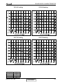
Capacity Correction Factor Due to Tubing Length
5.6.1
Cooling
Model
3m
1.02
7.5m
1
TOTAL TUBING LENGTH
10m 15m 20m 25m 30m
0.98 0.96 0.95 0.95 0.93
40m
---
50m
---
ז
* Minimum recommended tubing length between indoor and outdoor units is 3m.w
5.6.2
Heating
Model
3m
1.02
7.5m
1
TOTAL TUBING LENGTH
10m 15m 20m 25m 30m
0.98 0.96 0.95 0.95 0.93
40m
---
50m
---
* Minimum recommended tubing length between indoor and outdoor units is 3m.
5.7
Fresh air volume to the external static pressure (Field option)
Knock-down opening :φ100mm on the casing for the fresh duct
Fresh air control: by external booster fan
Select the fresh air volume according to required external static pressure.
Fresh Air Volume(m3/h)
Fresh air volume Vs. ESP
70.0
60.0
50.0
40.0
30.0
20.0
10.0
0.0
10
15
20
25
30
35
40
ESP(Pa)
5.8
Conditioned air supply to adjacent room (Field option)
(To be finished)
SM CK 1-A.1 GB
CONTENT
5-21
SOUND LEVEL CHARACTERISTICS
6.
SOUND LEVEL CHARACTERISTICS
6.1
Sound Pressure Level
1.5m
Unit
Mic.
Figure 1
6.2
Soud Pressure Level Spectrum (Measured as Figure 1)
CK 35
NC-70
NC-60
NC-50
NC-40
NC-30
APPROXIMATE
THRESHOLD OF
HEARING FOR
CONTINUOUS
NOISE
NC-20
OCTAVE BAND SOUND PRESSURE LEVEL, dB re 0.002 MICRO BAR
OCTAVE BAND SOUND PRESSURE LEVEL, dB re 0.002 MICRO BAR
CK 25
BAND CENTER FREQUENCIES, Hz
FAN SPEED
NC-70
NC-60
NC-50
NC-40
NC-30
APPROXIMATE
THRESHOLD OF
HEARING FOR
CONTINUOUS
NOISE
NC-20
BAND CENTER FREQUENCIES, Hz
LINE
HI
ME
LO
SM CK 1-A.1 GB
CONTENT
6-1
SOUND LEVEL CHARACTERISTICS
CK 60
NC-70
NC-60
NC-50
NC-40
NC-30
APPROXIMATE
THRESHOLD OF
HEARING FOR
CONTINUOUS
NOISE
NC-20
OCTAVE BAND SOUND PRESSURE LEVEL, dB re 0.002 MICRO BAR
OCTAVE BAND SOUND PRESSURE LEVEL, dB re 0.002 MICRO BAR
CK 50
NC-70
NC-60
NC-50
NC-40
NC-30
APPROXIMATE
THRESHOLD OF
HEARING FOR
CONTINUOUS
NOISE
NC-20
BAND CENTER FREQUENCIES, Hz
BAND CENTER FREQUENCIES, Hz
OCTAVE BAND SOUND PRESSURE LEVEL, dB re 0.002 MICRO BAR
CK 70
NC-70
NC-60
NC-50
NC-40
NC-30
APPROXIMATE
THRESHOLD OF
HEARING FOR
CONTINUOUS
NOISE
NC-20
BAND CENTER FREQUENCIES, Hz
FAN SPEED
LINE
HI
ME
LO
6-2
CONTENT
SM CK 1-A.1 GB
SOUND LEVEL CHARACTERISTICS
6.3
Outdoor units
MODEL
Indoor
Outdoor
CK 25
DCI 25
CK 35
DCI 35
CK 50
DCI 50
CK 60
DCI 60
CK 70
DCI 72Z
SPL dB(A)
SPW dB(A)
Cooling/Heating Cooling/Heating
50/51
60/61
52/52
62/62
52/53
62/63
55/55
65/65
56/56
66/66
Unit
1m
Mic.
Ground
Figure 2
6.4
Sound Pressure Level Spectrum (Measured as Figure 2)
DCI 25 Cooling
SM CK 1-A.1 GB
DCI 25 Heating
CONTENT
6-3
SOUND LEVEL CHARACTERISTICS
FAN SPEED
DCI 35 Cooling
DCI 35 Heating
DCI 50 Cooling
DCI 50 Heating
LINE
HI
ME
LO
6-4
CONTENT
SM CK 1-A.1 GB
SOUND LEVEL CHARACTERISTICS
DCI 60 Cooling
DCI 60 Heating
DCI 72 Cooling
DCI 72 Heating
FAN SPEED
LINE
HI
ME
LO
SM CK 1-A.1 GB
CONTENT
6-5
ELECTRICAL DATA
7.
ELECTRICAL DATA
7.1
Single Phase Units
MODEL
CK 25 DCI
CK 35 DCI
CK 50 DCI
CK 60 DCI
CK 70 DCI
To indoor
To indoor
To indoor
To indoor
To outdoor
1PH-230V-50Hz
1PH-230V-50Hz
1PH-230V-50Hz
1PH-230V-50Hz
1PH-230V-50Hz
Max Current, A
10
10
12
13
14
Inrush Current A
35
35
35
35
45
Starting Current A
10.5
10.5
10.5
10.5
10.5
Circuit Breaker A
Power Supply
16
16
20
20
20
Power Supply Wiring No.X Cross
Section mm2
3 x 1.5 mm2
3 x 1.5 mm2
3 x 2.5 mm2
3 x 2.5 mm2
3 x 2.5 mm2
Interconnecting Cable No.X Cross
Section mm2
4 x 1.5 mm2
4 x 1.5 mm2
4 x 2.5 mm2
4 x 2.5 mm2
4 x 2.5 mm2
NOTE
Power wiring cord should comply with local lows and electrical
regulations requirements.
SM CK 1-A.1 GB
CONTENT
7-1
WIRING DIAGRAMS
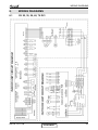
8.
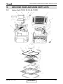
WIRING DIAGRAMS
8.1
CK 25, 35, 50, 60, 70 DCI
SM CK 1-A.1 GB
CONTENT
8-1
WIRING DIAGRAMS
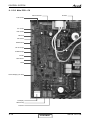
Outdoor Unit: DCI 72Z
CHOKE
COIL REVERSE BASE
HEATER
U V W P 13
P3 P9 P11
VALVE
BLUE
OFAN
(OPTIONAL)
1 2 3 4 5 6
1 2
P4
P1 4
1 2
P1
1 2 1 2 1 2 1 2 1 2
P19 P20 P2
P8 P5
1
P6
ODU CONTROLLER PCBA
P10
L N COM N-COM
P7
6 5 4 3 2 1
JP9
1 2 3 4 5 6
P12
EARTH
FERRITE
CORE
Y/G
EEV
AC MAINS
EMI FILTER PCBA
EARTH
EARTH
BLACK
RED
BLUE
BROWN
8-2
OCT CTT OAT OMT HST
NCOM
COM
N-F
L-F
COM
N
L
L
FUSE
N
RED
BROWN
BLUE
RED
BROWN
BLUE
L N C L N
BLK
BRN
RED
COMP
WHITE
8.2
TO
IDU
FERRITE CORE
CONTENT
SM CK 1-A.1 GB
REFRIGERATION DIAGRAMS
9.
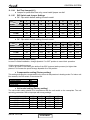
REFRIGERATION DIAGRAMS
9.1
CK 25, 35, 50, 60, 70 DCI
Cooling Mode
EEV
Heating Mode
EEV
SM CK 1-A.1 GB
CONTENT
9-1
TUBING CONNECTIONS
10.
TUBING CONNECTIONS
TUBE (Inch)
¼”
⅜”
½”
⅝”
¾”
11-13
13-20
11-13
40-45
13-20
11-13
60-65
18-25
11-13
70-75
18-25
11-13
80-85
40-50
11-13
TORQUE (Nm)
Flare Nuts
Valve Cap
Service Port Cap
1.
2.
3.
4.
5.
6.
7.
8.
Valve Protection Cap-end
Refrigerant Valve Port (use Allen wrench to open/close)
Valve Protection Cap
Refrigerant Valve
Service Port Cap
Flare Nut
Unit Back Side
Copper Tube
When the outdoor unit is installed above the indoor unit an oil trap is required every 5m along the suction
line at the lowest point of the riser. Incase the indoor unit is installed above the outdoor, no trap is
required.
SM CK 1-A.1 GB
CONTENT
10-1
CONTROL SYSTEM
11.
CONTROL SYSTEM
11.1
General Functions and Operating RulesThe DCI software is fully
parametric.
All the model dependent parameters are shown in Blue color and with Italic style [parameter].
The parameters values are given in the last section of this control logic chapter of the service manual.
11.1.1
System Operation Concept
The control function is divided between indoor and outdoor unit controllers. Indoor unit is the system
‘Master’, requesting the outdoor unit for cooling/heating capacity supply. The outdoor unit is the
system ‘Slave’ and it must supply the required capacity unless it enters into a protection mode
avoiding it from supplying the requested capacity.
The capacity request is transferred via indoor to outdoor communication, and is represented by a
parameter called ‘NLOAD’. NLOAD is an integer number with values between 0 and 127, and it
represents the heat or cool load felt by the indoor unit.
11.1.2
11.1.2.1
Compressor Frequency Control
NLOAD setting
The NLOAD setting is done by the indoor unit controller, based on a PI control scheme.
The actual NLOAD to be sent to the outdoor unit controller is based on the preliminary LOAD
calculation, the indoor fan speed, and the power shedding function.
NLOAD limits as a function of indoor fan speed:
Indoor Fan Speed Maximum NLOAD Cooling Maximum NLOAD Heating
Indoor Fan Speed
Low
Medium
High
Turbo
Auto
Maximum NLOAD Cooling
MaxNLOADIF1C
MaxNLOADIF2C
MaxNLOADIF3C
MaxNLOADIF4C
MaxNLOADIF5C
Maximum NLOAD Heating
MaxNLOADIF1H
MaxNLOADIF2H
MaxNLOADIF3H
MaxNLOADIF4H
MaxNLOADIF5H
NLOAD limits as a function of power shedding:
Mode
Cooling
Heating
11.1.3
11.1.3.1
Power Shedding OFF
No limit
No limit
Power Shedding ON
Nominal Cooling
Nominal heating
Target Frequency Setting
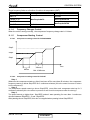
Target Frequency Setting for DCI 25/35/50/60/72Z
The compressor target frequency is a function of the NLOAD number sent from the indoor controller
and the outdoor air temperature.
Basic Target Frequency Setting:
Up to SW 35V12
NLOAD
<10
10
11-126
127
SM CK 1-A.1 GB
Target Frequency [Hz]
0
MinFreqC in cool OR MinFreqH in heat mode
NLOAD (as long it is in the allowed range, if not, the MinFreqC or Max FreqC in
cool mode OR MinFreqH or MaxFreqH in heat mode will be selected).
MaxFreqC in cool OR MaxFreqH in heat mode.
CONTENT
11-1
CONTROL SYSTEM
SW 35V14 and above
NLOAD
Target Frequency [Hz]
0
0
0 < NLOAD ≤ MinFreq
MinFreq
> MinFreq
MaxFreq MinFreq
{min (NLOAD, LoadDeadZone) MinFreq} MinFreq
LoadDeadZone MinFreq
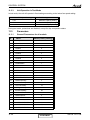
Differences between Old and New ODU DCI/DCR software
Unit
DCI
Current software
35V12
New software
35V14
Comment: there is no use for 35V13 software. This software is used in the past for Nordic countries. However, currently
it’s stopped completely from being used.
Graphical Illustration:
Target
Frequency
MaxFreq
LoadDeadZone
allowed in this range
Minimum Allowed
Linearization
Maximum Allowed
Linearization
MinFreq
(
MaxFreq
MinFreq
Mode
MaxFreq
MinFreq
LoadDeadZone
#
1
2
3
4
5
6
7
8
11-2
Name
MinFreqC
MaxFreqC
MaxFreqCRunPhase
MinFreqH
MaxFreqH
MaxFreqHRunPhase
LoadDeadZoneC
LoadDeadZoneH
NLOAD
)
LoadDeadZone
127
During initial period
(Start Phase)
After initial period
(Run Phase)
MaxFreqC
MaxFreqH
MaxFreqCRunPhase
MaxFreqHRunPhase
Cool
Heat
Cool
Heat
Cool
Heat
MinFreqC
MinFreqH
LoadDeadZoneC
LoadDeadZoneH
A
Single
DCI-25
30
64
64
30
81
81
90
127
B
Single
DCI-35
33
80
80
35
93
93
95
127
C
Single
DCI-50
20
85
85
20
95
95
95
127
D
Single
DCI 60
20
95
95
26
94
94
111
127
CONTENT
E
Duo
50
20
97
97
26
106
106
97
106
F
DCR
50
20
77
77
26
79
79
90
127
G
Duo
Delta38
38
93
85
38
100
90
93
100
H
Trio
Delta52
20
100
95
25
100
95
127
100
I
DCR
50T
20
77
77
26
79
79
90
127
SM CK 1-A.1 GB
CONTROL SYSTEM
Target frequency limits as a function of outdoor air temperature (OAT):
OAT Range
Cooling Mode limits
OAT < 6
No limit
6 ≤ OAT < 15
MaxFreqAsOATC
15≤ OAT<28
28≤ OAT
11.1.4
Heating Mode limits
MaxFreqAsOAT1H
MaxFreqAsOAT2H
No limit
Frequency Changes Control
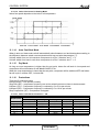
When the unit is running normally , the compressor frequency change rate is 1 Hz/sec.
11.1.5
11.1.5.1
Compressor Starting Control
Compressor starting control for DCI25/35/50/60
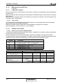
Step3
Step2
Step1
1
Minute
11.1.5.2
1
Minute
Time
Min 10 Minutes
Compressor starting control for DCI72Z
Step 1
Whenever the compressor starts up, after it has been off for more than 45 minutes, the compressor
frequency cannot go below Step1RPS for 3 continuous minutes (this rule comes to ensure oil return
to the compressor).
Step 2
The compressor speed cannot go above Step2RPS once after each compressor start up for 3
continuous minutes (this rule comes to prevent oil exit from the compressor after its start up).
Step 3
The speed cannot go higher than Step3RPS unless it was operating for more than 1 continuous
minutes between Step3RPS – 5 and Step3RPS .
After passing above Step3RPS, this rule is re-applied when passing below Step3RPS-5.
SM CK 1-A.1 GB
CONTENT
11-3
CONTROL SYSTEM
11.1.6
Minimum On and Off Time
3 minutes
11.1.7
Indoor Fan Control
8 Indoor fan speeds are determined for each model. 4 speeds for cool/dry/fan modes and 4speeds
for heat mode.
When user sets the indoor fan speed to a fixed speed (Low/ Medium/ High), unit will operate constantly
at set speed.
When Auto Fan is selected, indoor unit controller can operate in all speeds. The actual speed is set
according to the cool/heat load.
11.1.7.1
Turbo Speed
The Turbo speed is activated during the first 30 minutes of unit operation when auto fan speed is
selected and under the following conditions:
Difference between set point and actual room temperature is bigger then 3 degrees.
Room temperature > 22 for cooling, or < 25 for heating.
11.1.8
Outdoor Fan Control
11.1.8.1
Outdoor Fan Control for DCI25/35/50/60
7 outdoor fan speeds are determined for each model. 3 speeds for cool and dry modes, and 3speeds
for heat mode, and a very low speed.
Outdoor fan speed is a function of compressor frequency and outdoor air temperature (OAT).
4 routines for fan control are determined. The control routine selection depends on operation mode,
compressor speed, outdoor air temperature (OAT) and heat sink temperature (HST).
Routine
Conditions
Heating with OAT < 15ഒ or
Cooling with OAT > 20ഒ, or Faulty OAT
Cooling with 20ഒ > OAT > 7ഒ
Cooling with 7ഒ > OAT
Heating with OAT > 15ഒ
A
B
C
D
OFAN Speed
Compressor
Target Frequency
Freq=0
10 ≤ Freq < OFLowFreq
OFLowFreq
OFMedFreq
≤
OFMedFreq≤ Freq
11-4
Freq<
Routin
A
OFF
Low
Routin
B
OFF
Low
Routin
C
OFF
VL
Routin
D
OFF
Low
Medium
Low
VL
Low
High
Low
Low
Medium
CONTENT
SM CK 1-A.1 GB
CONTROL SYSTEM
OFAN State
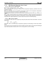
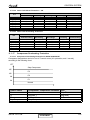
at Cool Mode $
HST
3 Degrees
Change To Higher
OFAN Cool state (*1)
3 Degrees
%
50
&
2$7
45
Change To lower
OFAN Cool state
Note: Periorities A>B>C
(*1) If
State C, change to B
If State B, change to A
When compressor is switched to OFF and the heat sink temperature is above 55 degrees, the
outdoor fan will remain ON in low speed for up to 3 minutes.
11.1.8.2
Outdoor Fan Control for DCI72Z
OFAN operates between OFMinRPM to OFMaxRPM.
Min time for speed change of OFAN OFMinTimeReduce (60 seconds).
There are 4 defined speeds – High, Med, Low, and Very Low.
The actual OFAN speeds in cool mode are defined according to the following table:
Freq
0
15
25
35
45
55
65
75
85
95
-10
0
80
130
160
205
250
275
300
325
350
-5
0
100
140
180
230
280
315
350
395
440
0
0
120
160
210
260
310
355
400
445
490
Outdoor air temperature (OAT)
5
10
15
20
25
30
0
0
0
0
0
0
130 220 340 460 580 600
190 250 380 600 610 670
250 330 470 730 730 730
320 440 600 730 730 730
390 550 730 730 730 730
470 640 730 730 730 730
550 730 730 730 730 730
630 730 730 730 730 730
710 730 730 730 730 730
35
0
730
730
730
730
730
730
730
730
730
40
0
730
740
780
800
800
800
800
800
800
46
0
730
750
800
850
850
850
850
850
850
The actual OFAN speeds in heat mode are defined according to the following table
Freq
0
15
25
35
45
55
65
75
85
95
-15
0
850
850
850
850
850
850
850
850
850
Outdoor air temperature (OAT)
-7
0
7
14
21
24
0
0
0
0
0
0
850 750 750 500 350 300
850 750 750 520 370 320
850 750 750 540 390 340
850 750 750 560 410 360
850 750 750 580 430 380
850 750 750 600 450 400
850 750 750 620 470 420
850 750 750 640 490 440
850 750 750 650 500 450
The fan speed is also related to protections and OMT value.
SM CK 1-A.1 GB
CONTENT
11-5
CONTROL SYSTEM
11.1.9
EEV (Electronic Expansion Valve) Control
11.1.9.1
EEV Control for DCI25/35/50/60
EEV opening is defined as EEV = EEVOL + EEVCV
EEVOL is the initial EEV opening as a function of the compressor frequency, operation mode, unit
model and capacity.
EEVCV is a correction value for the EEV opening that is based on the compressor temperature.
During the first 5 minutes of compressor operation EEVCV = 0.
Once the first 5 minutes are over, the correction value is calculated as follow: EEVCV(n) = EEVCV(n-1)
+ EEVCTT
EEVCTT is the correction based on the compressor temperature. A target compressor temperatureзs
set depending on frequency and outdoor air temperature, and the actual compressor temperature is
compared to the target temperature to set the required correction to the EEVopening.
11.1.9.2
EEV Control for DCI72Z
The target EEV value is the sum of open loop value (OL) and a result of the accumulative correction
values (CV).
EEV EEVOL EEVCV
Initial EEV value is set according to compressor frequency and according to indoor and outdoor
model
The corrective value is calculate every 30 sec the EEV corrective value is set to keep the discharged
super heat temperature between 20º to 30º in cooling and 12º to 20º in heating.
11-6
CONTENT
SM CK 1-A.1 GB
CONTROL SYSTEM
11.1.10
RV(Reversing Valve) Control
Reversing valve is on in heat mode.
Switching of RV state is done only after compressor is off for over 3 minutes.
11.1.10.1 Ioniser Control
Ioniser is on when unit is on ,AND indoor fan is on ,AND Ioniser power switch (on grille) is on.
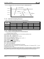
11.1.10.2 Base Heater Control
The base heater will be working only when RV is “ON” according to the following graph:
Base
Heater
OFF
ON
0
2
OAT
When OAT is faulty the base heater will be “ON” continuously in HEAT mode.
11.1.11
Fan Mode
In high/ medium/ low indoor fan user setting, unit will operate fan in selected speed.
In AutoFan user setting, fan speed will be adjusted automatically according to the difference between
actual room temperature and user set point temperature.
11.1.12
Cool Mode
NLOAD is calculated according to the difference between actual room temperature and user set
point temperature by fuzzy control.
In high/ medium/ low indoor fan user setting, unit will operate fan in selected speed.
In AutoFan user setting, fan speed will be adjusted automatically according to the calculated
NLOAD.
11.1.13
Heat Mode
NLOAD is calculated according to the difference between actual room temperature and user set
point temperature by fuzzy control.
In high/ medium/ low indoor fan user setting, unit will operate fan in selected speed.
In AutoFan user setting, fan speed will be adjusted automatically according to the calculated
NLOAD.
11.1.11.1 Temperature Compensation
In ducted and cassette models, 3 degrees are reduced from room temperature reading (except when
in I-Feel mode), to compensate for temperature difference between high and low areas in the heated
room, and for coil heat radiation on room thermistor.
The temperature compensation can be enabled/disabled by shortening of J2 on the indoor unit
Controller
Model
Cassette
Ducted
SM CK 1-A.1 GB
J2 Shorted
Compensation Enabled
Compensation Enabled
CONTENT
J2 Opened
Compensation Disabled
Compensation Disabled
11-7
CONTROL SYSTEM
11.1.11.2 Indoor Fan Control in Heating Mode
Indoor fan speed depends on the indoor coil temperature:
11.1.14
Auto Cool/Heat Mode
When in auto cool heat mode unit will automatically select between cool and heat mode according to
the difference between actual room temperature and user set point temperature (.T).
Unit will switch from cool to heat when compressor is off for 3 minutes, and .T < -3.
Unit will switch from heat to cool when compressor is off for 5 minutes, and .T < -3.
11.1.15
Dry Mode
As long as room temperature is higher then the set point, indoor fan will work in low speed and
compressor will work between 0 and MaxNLOADIF1C Hz.
When the room temperature is lower than the set point, compressor will be switched OFF and indoor
fan will cycle 3 minutes OFF, 1 minute ON.
11.1.16
Protections
There are 5 protection codes.
Normal (Norm) – unit operate normally.
Stop Rise (SR) – compressor frequency can not be raised but does not have to be decreased.
HzDown1 (D1) – Compressor frequency is reduced by 2 to 5 Hz per minute.
HzDown2 (D2) – Compressor frequency is reduced by 5 to 10 Hz per minute.
Stop Compressor (SC) – Compressor is stopped.
11.1.16.1 Indoor Coil Defrost Protection — CK
Min(ICT,ICTE)
< -2
[-2, 0)
[0, 2)
[2, 4)
[4, 6)
[6, 8]
>8
11-8
Trend
Fast Increasing
SC
D1
SR
SR
Norm
Norm
Increasing
SC
D1
SR
SR
Norm
Norm
No Change
SC
D2
D1
SR
SR
Norm
Norm
CONTENT
Decreasing
SC
D2
D2
D1
SR
SR
Fast Decreasing
SC
D2
D2
D2
D1
SR
SM CK 1-A.1 GB
CONTROL SYSTEM
11.1.16.2 Indoor Coil Defrost Protection — CK
ICT
< -2
[-2, 0)
[0, 2)
[2, 4)
[4, 6)
[6, 8]
>8
Trend
Fast Increasing
SC
D1
SR
SR
Norm
Norm
Increasing
SC
D1
SR
SR
Norm
Norm
No Change
SC
D2
D1
SR
SR
Norm
Norm
Decreasing
SC
D2
D2
D1
SR
SR
Fast Decreasing
SC
D2
D2
D2
D1
SR
11.1.16.3 Indoor Coil Overheating Protection
ICT
ICT Trend
Fast Decreasing
>62
[60, 62)
[55, 60)
[52, 55)
[48, 52)
[45, 48)
I<45
11.1.17
SC
D1
SR
SR
Norm
Norm
Decreasing
SC
D1
SR
SR
Norm
Norm
No Change
Increasing
Fast Increasing
SC
D2
D1
SR
SR
Norm
Norm
SC
D2
D2
D1
SR
SR
SC
D2
D2
D2
D1
SR
Compressor Overheating Protection
11.1.17.1 Compressor Overheating Protection for DCI25/35/50/60/72Z
Compressor temperature can be in one of 5 control zones (4 in protection, and 1 normal),
according to the following chart.
CTT
105
102
98
94
Stop-Compressor
P3
P2
P1
Normal
Control Status
Compressor Temperature Increases Else
P1
P2
P3
Stop Compressor
Normal
HzDown 1
HzDown 2
Stop Compressor
SM CK 1-A.1 GB
CONTENT
Stop Rise
Stop Rise
HzDown 1
11-9
CONTROL SYSTEM
11.1.17.2 Compressor Over Current Protection Only For DCI25/35/50/60/72Z
CCR
Stop-Compresor
CCROC4
HzDown2
CCROC3
HzDown1
CCROC2
Stop-Rise
CCROC1
Normal
11.1.18
Heat Sink Overheating Protection
11.1.08.1 Heat Sink Overheating Protection For DCI25/35/50/60/72Z
HST Trend
HST
Fast Decreasing
≥ 90
[85, 90)
[82, 85)
[80, 82)
[78 , 80)
< 78
11.1.19
SC
D1
SR
SR
Norm
Decreasing
SC
D1
SR
SR
Norm
No Change
SC
D2
D1
SR
Norm
Norm
Increasing
SC
D2
D2
D1
SR
Fast Increasing
SC
D2
D2
D1
SR
Outdoor Coil Deicing Protection
11.1.19.1 Outdoor coil Deicing Protection For DCI25/35/50/60/72Z
•
Entering Deicing Conditions
Deicing operation will start when either one of the following conditions exist:
Case 1: OCT < OAT – 8 AND TLD > DI
Case 2: OCT < OAT – 12 AND TLD > 30 minutes.
Case 3: OCT is Invalid AND TLD > DI
Case 4: Unit is just switched to STBY AND OCT < OAT – 8
Case 5: NLOAD = 0 AND OCT < OAT -8
Case 6: OCT<-19 AND TLD>60 minutes
All this condition will exist during 10 seconds
OCT – Outdoor Coil Temperature
OAT – Outdoor Air Temperature
TLD – Time from Last Deicing
DI – Deicing Interval (Time Interval Between Two Deicing)
Deicing interval time when compressor is first started in heat mode, is 10 minutes if OCT < -2, and
is 40 minutes in other cases.
Deicing interval time is changed (increased/ decreased in 10 minutes steps) as a function of deicing
time. If deicing time is shorter then former deicing time, the deicing interval time will be increased. If
deicing time is longer then former deicing time, the deicing interval time will be decreased.
11-10
CONTENT
SM CK 1-A.1 GB
CONTROL SYSTEM
•
Deicing Operation Procedure
OCT
12
0
T h re s h o ld
COMP
ON
T1
T1
T2
DT
m a x. 1 2 m in u te s
D e ic e F re q C h R V
HEAT
RV
T3
COOL
O FAN
T3
ON
OFF
E E V D e ic e rO p e n
EEV
Any
T1=60 secondes;T2=36 secondes;T3=6 secondes
T1=50 secondes;T2=36 secondes;T3=6 secondes
11.1.20
Condensate Water Over Flow Protection
P1
P2
P3
P4
Level Connector Top View
Each of the pins P1, P2, P3 can have two options:
1 – When it is shorted with P4
0 – When it is not shorted to P4
P1
P2
P3
Level
Don’t care
Don’t care
1
Normal
Don’t care
Don’t care
0
Overflow
(*) 1- Pin P1, P2, or P3 is connected to P4.
0- Pin P1, P2 or P3 is not connected to P4.
For CK unit:
In case of vertical installation, change dipswitch 7 to OFF position to cancel Water Pump operation.
SM CK 1-A.1 GB
CONTENT
11-11
CONTROL SYSTEM
Overflow when
unit is ON
Overflow
Water Level
Overflow when
unit is OFF
Normal
ON
OPER
LED
OFF
BLINK
ANY
NLOAD
NLOAD is
forced to 0
0
ON
PUMP
OFF
8 min
11.1.21
8 min
8 min
Operating the Unit from Mode Button (On display)
Forced operation allows to start, stop and operate in Cooling or Heating, in pre-set temperature
according to the following table:
Forced operation Mode
Cooling
Heating
11.1.22
11.1.22.1
Pre-set Temperature
20ഒ
28ഒ
On Unit Controls and Indicators
Indoor Unit controller Controls and Indicatiors for All Models Except for Floor/Ceiling
model
During OFF, Fan, Cool, Heat, Dry, and Auto modes (for operation in other modes, see at the relevant
spec paragraph):
STAND BY/OPERATION
INDICATOR
ESF/INOIZER INDICATOR
TIMER INDICATOR
FILTER INDICATOR
MODE/RESET BUTTON
11-12
Lights up when the Air Conditioner is connected to power and ready
to receive the R/C commands
Lights up during operations. Blinks when compressor is stopped as
a result of a thermodynamic protection.
Lights up during ESF/ ionizer operation.
Lights up during Timer and Sleep operation.
Lights up when Air Filter needs to be cleaned.
Every short pressing , the next operation mode is selected, in this
order :
SB → Cool Mode → Heat Mode → SB → …
Press to turn off the filter indicator and to reset the filter function,
after the cleaned filter has been reinstalled.
In long pressing the system enters into diagnostic mode.
CONTENT
SM CK 1-A.1 GB
CONTROL SYSTEM
11.1.22.2 Outdoor Unit controller Indicatiors
Unit has three LED’s.
SB LED is ON when power is ON (230 VAC, even when no communication).
STATUS LED is ON when COMP is ON, and Blinks according to diagnostics mode definitions when
either fault or protection occurs.
FAULT LED Blinks according to diagnostics mode definitions when either fault or protection occurs.
11.1.23
DIP switch settings
Indoor Unit Controller
11.1.23.1 Power PCB - CK
PUMP
Wire to Main PCB
DC Motor Cable
11.1.23.2 Main PCB - CK
Self Test Jumper
DIP Switch
M2L Port
MCU Flash Port
12Pin Displayer Cable
Alarm Output
Unit On Output
RC-W
RC-W Power
PD/PS
Safety switch Terminals
ICTE Sensor
Inoizer
ICT Sensor
ESF
RAT Sensor
Swing Motor
Water Level
SM CK 1-A.1 GB
CONTENT
11-13
CONTROL SYSTEM
11.1.23.3 Main PCB − CK
MCU Flash Port
IF Motor
ICTE sensor
ICT sensor
RAT sensor
M2L Port
DIP Switch
WATER level
Unit On output
ALARM output
CLOCK
RCW Power
RCW
16 Pins Display (not used)
To Display
Water Pump
Fresh Air
11-14
CONTENT
SM CK 1-A.1 GB
CONTROL SYSTEM
11.1.24
Self Test Jumper(J1))
● Jumper for production line only, never install jumper on site!
11.1.25 DIP Switch and Jumper Settings
● CK - Dip switch default setting for each model
1
2
3
4
5
6
7
8
J2
J3
J6
J7
J8
J9
J12
J13
2.5 KW
ON
OFF
OFF
OFF
OFF
OFF
ON
OFF
3.5 KW
ON
OFF
OFF
ON
OFF
OFF
ON
OFF
5.0 KW
ON
ON
OFF
OFF
OFF
OFF
ON
OFF
6.0 KW
ON
ON
OFF
ON
OFF
OFF
ON
OFF
7.0 KW
ON
ON
OFF
OFF
ON
OFF
ON
OFF
DIP
MODEL
J
● CK - Dip switch default setting for each model
1
2
3
4
5
6
7*
8**
J2
J3
J5
J7
J8
J9
J10
J12
2.5 KW
ON
OFF
OFF
ON
OFF
OFF
ON
OFF
3.5 KW
ON
OFF
OFF
OFF
ON
OFF
ON
OFF
5.0 KW
ON
OFF
OFF
ON
ON
OFF
ON
OFF
6.0 KW
ON
ON
OFF
OFF
OFF
OFF
ON
OFF
7.0 KW
ON
ON
OFF
ON
OFF
OFF
ON
OFF
DIP
MODEL
J
*Water pump and float switch setting
In case of vertical installation, change dipswitch 7 to OFF position to cancel their operation.
**High external static pressure
There is an option of increasing the airflow if the ESP (external static pressure) is higher than
planned. To increase the speed change dipswitch 8 to ON position.
● Compensation setting (Factory setting)
This setting activates the compensation to the return air temperature in heating mode. For indoor unit
like cassette, the DIP switch J2 should be ON.
Compensation
Activated(factory setting)
Deactivated
J2
ON
OFF
● Unit model setting (Factory setting)
The unit model setting should be in accordance with the unit model on the nameplate. The unit
operating parameters will be improper with wrong settings.
Unit model(Capacity)
2.5kW model
3.5kW model
5.0kW model
6.0kW model
7.0kW model
SM CK 1-A.1 GB
J3
OFF
OFF
ON
ON
ON
J6
OFF
OFF
OFF
OFF
OFF
J7
OFF
ON
OFF
ON
OFF
CONTENT
J8
OFF
OFF
OFF
OFF
ON
11-15
CONTROL SYSTEM
●
Presence Detector/Power Shedding Selection
Select the functions of dry contact PD/PS by setting the Dip switch J9
Selection
Presence Detector
Power Shedding
●
J9
OFF
ON
Installation of height compensation settings (By installer)
The compensation settings according to installation height should be set by using the dip switch J12,
J13 on the controller PCB
Installation Height
H0
H1(Factory setting)
H2
H3
J12
OFF
ON
OFF
ON
J13
OFF
OFF
ON
ON
Installation height
2.1-2.7m
2.7-3.3m
>3.3m
Reserved
Compensation data according to the installation height
Installation
Height
H0
H1
H2
H3
11-16
Speed Compensation for
Heating Mode
Speed Compensation for
other Modes
Temperature compensation
in heating mode
CK
CK
CK
CK
CK
CK
-50
0
100
150
0
150
150
150
-50
0
100
150
0
150
150
150
4
4
6
7
2
2
2
2
CONTENT
SM CK 1-A.1 GB
CONTROL SYSTEM
IDU Diagnostic Table.
● Alarm Output
The Alarm Output dry contact will be on (closed), when a predefined set faults occur.
The fault set is defined under diagnostics section.
The alarm output will be off (open), when the predefined fault is cleared.
The indoor alarm outputs are defined according to the following IDU Diagnostic Table:
No
Problem
AO
5
4
3
2
1
1
ICT is disconnected
Yes
0
0
0
0
1
2
ICT is shorted
Yes
0
0
0
1
0
3
RAT is disconnected
Yes
0
0
0
1
1
4
RAT is shorted
Yes
0
0
1
0
0
5
Reserved (for MSMP used as RGT fault)
No
0
0
1
0
1
ICTE shorted/disconnected (when enabled)
Yes
0
0
1
1
0
7
Undefined IDU family/model
Yes
0
0
1
1
1
8
No Communication
Yes
0
1
0
0
0
9
No Encoder
No
0
1
0
0
1
10
Reserved
No
0
1
0
1
0
11
Outdoor Unit Fault
No
0
1
0
1
1
…
Reserved
No
17
Defrost protection
No
1
0
0
0
1
18
Deicing Protection
No
1
0
0
1
0
19
Outdoor Unit Protection
No
1
0
0
1
1
20
Indoor Coil HP Protection
No
1
0
1
0
0
21
Overflow Protection
Yes
1
0
1
0
1
22
Reserved
No
24
EEPROM Not Updated
No
1
1
0
0
0
25
Bad EEPROM
No
1
1
0
0
1
26
Bad Communication
No
1
1
0
1
0
27
Using EEPROM data
No
1
1
0
1
1
28
Model A
No
1
1
1
0
0
29
Model B
No
1
1
1
0
1
30
Model C
No
1
1
1
1
0
31
Model D
No
1
1
1
1
1
*6
* CK Unit only
SM CK 1-A.1 GB
CONTENT
11-17
CONTROL SYSTEM
OUD Diagnostic Table
AO - Alarm output
No
Problem
AO
5
4
3
2
1
1
OCT is disconnected
Yes
0
0
0
0
1
2
OCT is shorted
Yes
0
0
0
1
0
3
CTT is disconnected
Yes
0
0
0
1
1
4
CTT is shorted
Yes
0
0
1
0
0
5
HST is disconnected (when enabled)
Yes
0
0
1
0
1
6
HST is shorted (when enabled)
Yes
0
0
1
1
0
7
OAT is disconnected (when enabled)
Yes
0
0
1
1
1
8
OAT is shorted (when enabled)
Yes
0
1
0
0
0
9
TSUC is disconnected (when enabled)
Yes
0
1
0
0
1
10
TSUC is shorted (when enabled)
Yes
0
1
0
1
0
11
IPM Fault
Yes
0
1
0
1
1
12
Bad EEPROM
No
0
1
1
0
0
13
DC under voltage
Yes
0
1
1
0
1
14
DC over voltage
Yes
0
1
1
1
0
15
AC under voltage
Yes
0
1
1
1
1
16
Mismatch IDU & ODU models (*SW 35V14 and above)
Yes
1
0
0
0
0
17
No Communication
Yes
1
0
0
0
1
18
Reserved
No
1
0
0
1
0
20
Heat sink Over Heating
No
1
0
1
0
0
21
Deicing
No
1
0
1
0
1
22
Compressor Over Heating
No
1
0
1
1
0
23
Compressor Over Current
No
1
0
1
1
1
24
No OFAN Feedback
No
1
1
0
0
0
25
OFAN locked
Yes
1
1
0
0
1
26
Compressor Lock
Yes
1
1
0
1
0
27
Bad Communication
No
1
1
0
1
1
28
Missing ODU configuration (*SW 35V14 and above)
Yes
1
1
1
0
0
29
Undefined ODU Model (*SW 35V14 and above)
Yes
1
1
1
0
1
30
For future use
No
1
1
1
1
0
31
Operation condition is exceeded (*SW 35V14 and above)
Yes
1
1
1
1
1
*Alarm Output - is on SW 35V14 and above. There is no alarm on SW 35V12 and below/
● Unit ON Output
The ‘On/Off status’ dry contact will be on (closed), when the indoor mode is not STBY.
If the indoor mode is STBY mode, the ‘On/Off status’ will be off (open).
●
PD/PS(Presence Detector/Power Shedding)
Function
J9=open
J9=short
11-18
Presence Detector Connection
Power Shedding Function
Contact=open
Contact=short
Last Mode
No limit
Force to STBY
Limit NLOAD
CONTENT
SM CK 1-A.1 GB
CONTROL SYSTEM
11.1.25
Outdoor Unit Controller
11.1.25.1 Outdoor Unit Controller - Jumper setting
JP9 Jumper Layout
Reserved (PIN 9)
ODU3 (PIN 7)
ODU2 (PIN 5)
ODU1 (PIN 3)
ODU0 (PIN 1)
GND (PIN 10)
GND (PIN 8)
GND
GND
GND
11.1.26
(PIN 6)
(PIN 4)
(PIN 2)
ODU Model Selection
ODU3
ODU2
ODU1
ODU0
ODU Model
OFF
OFF
OFF
ON
A (Single DCI 25)
OFF
OFF
ON
OFF
B (Single DCI 35)
OFF
OFF
ON (PIN3 & PIN4)
ON (PIN1 & PIN2)
C (Single DCI 50)
OFF
ON (PIN5 & PIN6)
OFF
OFF
D (Single DCI 60)
ON (PIN7 & PIN8)
ON (PIN5 & PIN6)
OFF
OFF
L (Single DCI 72Z)
11.1.27
Outdoor Unit Controller
ON
1
N.A.
N.A.
ODU3
ODU2
ODU1
ODU0
11.1.27.1 Outdoor Unit Controller - DIP Switch setting
DIP
2
3
4
5
6
ODU MODEL SETTING
ODU3
ODU2
ODU1
ODU0
OFF
OFF
OFF
OFF
ON
OFF
OFF
OFF
ON
ON
OFF
ON
ON
OFF
OFF
ON
OFF
ON
OFF
OFF
11.2
Test Mode
11.2.1
Entering Test Mode
ODU MODEL
DCI 25
DCI 35
DCI 50
DCI 60
DCI 72Z
System can enter Test mode in two ways:
Automatically when the following conditions exists for 30 minutes continuously:
Mode = Cool, Set point = 16, Room temperature = 27(+1/-2), Outdoor temperature = 35(+2/-1)
Or
Mode = Heat, Set point = 30, Room temperature = 20±1, Outdoor temperature = 7±(+1/-2)
Manually when entering diagnostics with the following settings:
Mode = Cool, Set point = 16
Mode = Heat, Set point = 30
SM CK 1-A.1 GB
CONTENT
11-19
CONTROL SYSTEM
11.2.3
Unit Operation in Test Mode
In test mode, the unit will operate in fixed settings according to the indoor fan speed setting:
Indoor FAN Speed Setting
Unit Setting
Low
Minimum Capacity Setting
Turbo
Nominal Capacity Setting
Auto
Maximum Capacity Setting
During test mode, protections are disabled, except for stop compressor status.
11.3
Parameters
11.3.1
General Parameters for all models
#
Name
1
CVStep
0
2
Cool2Heat
3
3
Heat2Cool
3
4
ICTDef1
8
5
ICTDef2
6
6
ICTDef3
4
7
ICTDef4
2
8
ICTDef5
0
9
ICTDef6
-2
10
ICTDeltaDef1
1
11
ICTDeltaDef2
-1
12
ICTDeltaOH1
-1
13
ICTDeltaOH2
1
14
FLTRTime
1023
15
PITconst
30
16
STARTTIMETURBOH
10
17
IFANOffTimeDry
3
18
IFANOnTimeDry
1
19
ICTLowLimitDry
10
20
ICTHighLimitDry
12
21
ExtraNLOADDry
20
22
IFANMAXTimeH
150
23
IFANOffTimeH
4
24
IFANOnTimeH
3
25
IFANTimeHeat2STBY
30
26
MAXTURBOTIMEF
30
27
MAXTURBOTIMEC
30
28
MAXTURBOTIMEH
30
11-20
Values(Factory Setting)
CONTENT
SM CK 1-A.1 GB
CONTROL SYSTEM
11.3.2
Family Dependent Parameter
#
Name
CKA
CKB
CKA
CKB
1
BasicCV1
4
4
2
2
2
BasicCV2
4
4
2
2
3
BasicCV3
6
6
2
2
4
BasicCV4
7
7
2
2
5
Max_Swg
40
40
NA
NA
6
Min_H_Angle
5
5
NA
NA
7
Max_H_Angle
40
40
NA
NA
8
Min_C_Angle
5
5
NA
NA
9
Max_C_Angle
40
40
NA
NA
10
MTR_Cls_Dir
C
C
NA
NA
11
MTR_Cls_Dir_V
C
C
NA
NA
12
Max_Angle_V
NA
NA
NA
NA
13
Min_Angle_V
NA
NA
NA
NA
14
Max_Swg_V
NA
NA
NA
NA
15
IFSPCHNA
10
10
10
10
16
IFSPCHND
4
4
10
10
17
IFSPCHAA
6
6
6
6
18
IFSPCHAD
4
4
6
6
19
IFSTARTSPEED
670
670
670
670
20
ICTSTSpeed
25
25
25
25
21
ICTVLSpeed
28
28
28
28
22
ICTLSpeed
30
30
30
30
23
ICTHSpeed
32
32
32
32
24
ICTTSpeed
40
40
35
35
25
NLOADHForcedValue
60
60
60
60
26
ICTOH1
45
45
49
49
27
ICTOH2
48
48
51
51
28
ICTOH3
52
52
53
53
29
ICTOH4
55
55
55
55
30
ICTOH5
60
60
60
60
31
ICTOH6
62
62
62
62
32
ICTEEnable
1
1
0
0
SM CK 1-A.1 GB
CONTENT
11-21
CONTROL SYSTEM
11.3.3
Indoor Model Parameters:
C (CK72)
A (CK25)
B (CK35)
C (CK50)
A (CK60)
B (CK72)
CKB
B (CK 60)
CKA
A (CK50)
CKB
B (CK 35)
CKA
A (CK25)
Indoor Family
IFVLOWC
250
300
450
500
550
670
690
800
900
900
IFLOWC
450
450
550
600
650
740
730
860
960
980
IFMEDC
500
520
620
660
700
810
860
980
1050
1050
IFHIGHC
550
600
680
720
750
920
980
1100
1170
1200
IFTURBOC
650
700
800
900
1000
960
1060
1170
1240
1280
IFVLOWH
250
300
450
500
550
670
690
800
900
900
IFLOWH
450
450
550
600
650
740
730
860
960
980
IFMEDH
520
550
620
660
700
810
860
980
1050
1050
IFHIGHH
600
650
680
720
750
920
980
1100
1170
1200
IFTURBOH
650
700
850
950
1000
960
1060
1220
1240
1280
Cap .Group
0
1
3
3
4
0
1
3
3
4
NomLoadC
40
62
66
81
62
40
60
64
79
54
NomLoadH
52
67
67
81
57
57
70
73
82
57
MaxNLOADIF1C
47
42
55
56
50
127
127
127
127
127
MaxNLOADIF2C
70
60
78
81
70
127
127
127
127
127
MaxNLOADIF3C
127
127
127
127
127
127
127
127
127
127
MaxNLOADIF4C
127
127
127
127
127
127
127
127
127
127
MaxNLOADIF5C
127
127
127
127
127
127
127
127
127
127
IFAN_SPEED_COMP0_C
-50
-50
-50
-50
-50
0
0
0
0
0
IFAN_SPEED_COMP1_C
0
0
0
0
0
150
150
150
150
150
IFAN_SPEED_COMP2_C
100
100
100
100
100
150
150
150
150
150
IFAN_SPEED_COMP3_C
150
150
150
150
150
150
150
150
150
150
IFAN_SPEED_COMP0_H
-50
-50
-50
-50
-50
0
0
0
0
0
IFAN_SPEED_COMP1_H
0
0
0
0
0
150
150
150
150
150
IFAN_SPEED_COMP2_H
100
100
100
100
100
150
150
150
150
150
IFAN_SPEED_COMP3_H
150
150
150
150
150
150
150
150
150
150
1
1
1
1
1
1
1
1
1
1
Indoor Model
Parameter
ModelEnable
11-22
CONTENT
SM CK 1-A.1 GB
CONTROL SYSTEM
11.3.4
Outdoor Parameters
General Parameters ( for every software):
#
Name
Default Value
1
MinOFFTime
3
2
MinONTime
3
3
OFSPCH
4
4
Down1
3
5
Down2
10
6
DImin
30
7
DImax
120
8
TimeD
1
9
DTmin
2
10
DTmax
12
11
DIT
10
12
CTMRUP
15
13
DIF
30
14
TCT
10
15
HSTOH1
78
17
HSTOH2
80
18
HSTOH3
82
19
HSTOH4
85
20
HSTOH5
90
21
HSTOHDelta1
-1
22
HSTOHDelta2
1
23
EEVCVTConst
30
24
BalanceTime
5
25
EEVInitOpen
300
SM CK 1-A.1 GB
CONTENT
11-23
CONTROL SYSTEM
11.3.5
#
1
2
3
4
5
6
7
8
9
10
11
12
13
14
15
16
17
18
19
20
21
22
23
24
25
26
27
28
29
30
31
32
33
34
35
36
37
38
39
40
41
42
43
44
45
46
47
48
49
50
51
52
53
54
55
56
57
58
59
60
61
62
63
11-24
ODU Model Dependent Parameters ( 35V12 )
Outdoor Model
Parameter
MinFreqC
MaxFreqC
MinFreqH
MaxFreqH
NormAccel
NormDecel
Step1Freq
Step2Freq
Step3Freq
OFVL
OFLOWC
OFMEDC
OFMAXC
OFLOWH
OFMEDH
OFMAXH
OFANTESTMODEC
OFANTESTMODEH
OFDelTestMode
CTTOH1
CTTOH2
CTTOH3
CTTOH4
CCROC1
CCROC2
CCROC3
CCROC4
DEICT1
DEICT2
DEICT3
ProtFreqLimit
EEVDecierOpen
OptimDeicFreq
EEVMinOperOpenC
EEVMaxOperOpenC
EEVMinOperOpenH
EEVMaxOperOpenH
EEVNormRate
EEVHighRate
EEVMaxOpen
OFLowFreqC
OFMedFreqC
OFLowFreqH
OFMedFreqH
HeaterDisableFlag
DeiceFreqChRV
OATRefC
SUCT Enable
HST Enable
OAT Enable
OATRefH
MinTargCTTC
MaxTargCTTC
MinTargCTTH
MaxTargCTTH
DST
DSTF
OATLimitC
OATLimit1H
OATLimit2H
MaxFreqAsOATC
MaxFreqAsOAT1H
MaxFreqAsOAT2H
A
Single
DCI-25
B
Single
DCI-35
C
Single
DCI-50
D
Single
DCI 60
30
64
30
81
1
1
60
70
90
20
55
70
83
55
70
83
83
83
20
94
98
102
105
7.1
7.5
7.9
8.3
60
36
6
60
180
90
50
380
50
300
33
12
500
45
57
45
57
0
0
35
0
0
1
7
30
95
40
95
8
12
24
6
15
50
65
60
33
80
35
93
1
1
60
70
90
20
55
70
83
55
70
83
83
83
20
94
98
102
105
7.1
7.5
7.9
8.3
60
36
6
60
180
90
50
380
50
300
33
12
500
45
57
45
57
0
0
35
0
0
1
7
30
95
40
95
8
12
24
6
15
50
75
60
20
85
20
95
1
1
60
70
90
20
60
76
92
60
83
100
92
100
28
94
98
102
105
10
10.5
10.8
11.2
60
36
6
60
100
90
50
380
50
380
33
12
500
40
70
40
86
0
0
35
0
1
1
7
30
95
40
95
8
12
28
6
15
64
85
60
20
95
26
94
1
1
60
70
90
20
55
70
79
55
70
79
83
83
28
94
98
102
105
11.4
11.8
12.2
12.6
60
36
6
60
180
90
80
380
60
300
33
12
500
35
55
40
60
0
0
35
0
1
1
7
30
90
45
90
8
12
28
6
15
85
80
60
CONTENT
SM CK 1-A.1 GB
CONTROL SYSTEM
11.3.6
#
1
2
3
4
5
6
7
8
9
10
11
12
13
14
15
16
17
18
19
20
21
22
23
24
25
26
27
28
29
30
31
32
33
34
35
36
37
38
39
40
41
42
43
44
45
46
47
48
49
50
51
52
53
54
55
56
57
58
59
60
61
62
63
64
65
66
67
68
68
69
ODU Model Dependent Parameters ( 35V14 )
Outdoor Model
Parameter
MinFreqC
MaxFreqC
MaxFreqCRunPhase
MinFreqH
MaxFreqH
MaxFreqHRunPhase
LoadDeadZoneC
LoadDeadZoneH
NormAccel
NormDecel
Step1Freq
Step2Freq
Step3Freq
OFVL
OFLOWC
OFMEDC
OFMAXC
OFLOWH
OFMEDH
OFMAXH
OFANTESTMODEC
OFANTESTMODEH
OFDelTestMode
CTTOH1
CTTOH2
CTTOH3
CTTOH4
CCROC1
CCROC2
CCROC3
CCROC4
DEICT1
DEICT2
DEICT3
ProtFreqLimit
EEVDecierOpen
OptimDeicFreq
OCTExitDeicer
MaxDeicerTime
EEVMinOperOpenC
EEVMaxOperOpenC
EEVMinOperOpenH
EEVMaxOperOpenH
EEVNormRate
EEVHighRate
EEVMaxOpen
OFLowFreqC
OFMedFreqC
OFLowFreqH
OFMedFreqH
HeaterDisableFlag
DeiceFreqChRV
OATRefC
SUCT Enable
HST Enable
OAT Enable
OATRefH
MinTargCTTC
MaxTargCTTC
MinTargCTTH
MaxTargCTTH
DST
DSTF
OATLimitC
OATLimit1H
OATLimit2H
MaxFreqAsOATC
MaxFreqAsOAT1H
MaxFreqAsOAT2H
EnableExceedCond
SM CK 1-A.1 GB
A
Single
DCI-25
B
Single
DCI-35
C
Single
DCI-50
D
Single
DCI 60
30
64
64
30
81
81
90
127
1
1
60
70
90
20
55
70
83
55
70
83
83
83
20
94
98
102
105
7.1
7.5
7.9
8.3
60
36
6
60
180
90
12
12
50
380
50
300
33
12
500
45
57
45
57
0
0
35
0
1
1
7
30
95
40
95
8
12
24
6
15
50
65
60
0
33
80
80
35
93
93
95
127
1
1
60
70
90
20
55
70
83
55
70
83
83
83
20
94
98
102
105
7.1
7.5
7.9
8.3
60
36
6
60
180
90
12
12
50
380
50
300
33
12
500
45
57
45
57
0
0
35
0
1
1
7
30
95
40
95
8
12
24
6
15
50
75
60
0
20
85
85
20
95
95
95
127
1
1
60
70
90
20
60
76
92
60
83
100
92
100
28
94
98
102
105
10
10.5
10.8
11.2
60
36
6
60
100
90
12
12
50
380
50
380
33
12
500
40
70
40
86
0
0
35
0
1
1
7
30
95
40
95
8
12
28
6
15
64
85
60
0
20
95
95
26
94
94
111
127
1
1
60
70
90
20
55
70
79
55
70
79
83
83
28
94
98
102
105
11.4
11.8
12.2
12.6
60
36
6
60
180
90
12
12
80
380
60
300
33
12
500
35
55
40
60
0
0
35
0
1
1
7
30
90
45
90
8
12
28
6
15
85
80
60
0
CONTENT
11-25
CONTROL SYSTEM
11.3.7
ODU Model Dependent Parameters ( 36V1-S01 )
Outdoor Model
#
Parameter
11-26
L
Single
DCI-72Z
1
MinFreqC
15
2
MaxFreqC
70
3
MinFreqH
15
4
MaxFreqH
90
7
Step1Freq
35
8
Step2Freq
55
9
Step3Freq
90
10
OFMinRPM
8
11
OFMaxRPM
90
12
NightRPM
65
13
OFNNoiseMaxRPM
78
14
CTTOH1
90
15
CTTOH2
95
16
CTTOH3
100
17
CTTOH4
105
18
CCROC1
12.5
19
CCROC2
11.3
20
CCROC3
14.1
21
CCROC4
14.9
22
ProtFreqLimit
60
23
EEVMinOperOpenC
50
24
EEVMaxOperOpenC
480
25
EEVMinOperOpenH
50
26
EEVMaxOperOpenH
480
27
HeaterDisableFlag
0
28
HST Enable
1
29
OATLimitC
25
30
OATLimit1H
4
31
OATLimit2H
15
32
MaxFreqAsOATC
60
33
MaxFreqAsOAT1H
68
34
MaxFreqAsOAT2H
57
35
NormAccel
1
36
NormDecel
1
37
38
OCTExitDeicer
MaxDeicerTime
12
15
CONTENT
SM CK 1-A.1 GB
TROUBLESHOOTING
12.
TROUBLESHOOTING
WARNING!!!
When Power Up – the whole outdoor unit controller, including the wiring, is under
HIGH VOLTAGE!!!
Never open the Outdoor unit before turning off the Power!!!
When turned off, the system is still charged (400V)!!!
It takes about 3 Min. to discharge the system.
Touching the controller before discharging may cause an electrical shock!!!
For safe handling of the controller please refer to section 12.6 below.
12.1
General DCI Single Split System failures and Corrective Actions
PROBABLE
CAUSE
No
SYMPTOM
1
Power supply indicator (Red
LED) does not light up.
No power supply
Check power supply. If power supply
is OK, check display and display
wiring. if OK, replace controller.
2
Unit does not respond to
remote control message
Remote
control
message not reached
the indoor unit
Check remote control batteries, if
batteries are OK, check display and
display wiring, if OK, replace display
PCB.
If still not OK replace controller.
3
Unit responds to remote
control message but Operate
indicator (Green LED) does
not light up
Problem with display
PCB
Replace display PCB.
If still not OK replace controller.
Unit in heat mode and
coil is still not warm.
Change to cool mode and check.
Problem with PCB or
capacitor
Change to high speed and Check
power supply to motor is higher than
130VAC (for triack controlled motor)
or higher than 220VAC for fixed speed
motors, if OK replace capacitor, if not
OK replace controller
5
Indoor fan works when unit
is OFF, and indoor fan speed
is not changed by remote
control command.
PCB problem
Replace controller
6
Compressor does not start
Electronics control
problem or protection
Perform diagnostics (See 12.3), and
follow the actions described.
7
Compressor stops during
operation and Green LED
remains on
Electronic control
or power supply
problem
Perform diagnostics (See 12.3), and
follow the actions described.
4
Indoor fan does not start
(louvers are opened and
Green LED does light up)
SM CK 1-A.1 GB
CONTENT
CORRECTIVE ACTION
12-1
TROUBLESHOOTING
No
SYMPTOM
PROBABLE
CAUSE
CORRECTIVE ACTION
8
Compressor is on but outdoor
fan does not work
Problem with outdoor
electronics or
outdoor fan
Check outdoor fan motor according
to the procedure in section 12.5.3 , if
not OK replace controller
9
Unit works in wrong mode
(cool instead of heat or heat
instead of cool)
Electronics or power
connection to RV
Check RV power connections, if OK,
Check RV
operation with direct
230VAC power supply, if OK,
Replace outdoor controller.
10
All components are operating
properly but no cooling or no
heating
Refrigerant leak
Check refrigeration system.
11
Compressor is over heated
and unit does not generate
capacity
EEV problem
Check EEV
12
Units goes into protections
and compressor is stopped
with no clear reason
Control problem or
refrigeration system
problem
Perform diagnostics (See 12.3), and
follow the actions described.
13
Compressor
motor
generating noise and
suction occurs
Phase order to
compressor is wrong
Check compressor phase order.
14
Water leakage from indoor
unit
Indoor unit drainage
tube is blocked
Check and open drainage tube.
15
Freezing of outdoor unit in
heat mode and outdoor unit
base is blocked with ice
16
Unit operates with wrong fan
speeds or wrong frequency
12.2
is
no
Connect base heater.
Wrong jumper
settings
Perform diagnostics (See 12.3), and
check if units is operating by EEPROM
parameters.
Checking the refrigeration system
Checking system pressures and other thermodynamic measures should be done when system
is in Test Mode (in Test mode, system operates in fixed settings). The performance curves
given in this manual are given for unit performance in test mode when high indoor fan speed is
selected.
Entering test mode:
Set unit to Cool/16 degrees/High indoor fan speed, or Heat/30 degrees/High indoor fan speed,
and enter diagnostics.
12.3
Judgment by Indoor/Outdoor Unit Diagnostics
Enter diagnostics mode - press for five seconds Mode button in any operation mode.
Acknowledgment is by 3 short beeps and lights of COOL and HEAT LED’s. Then, every short
pressing of Mode button will scroll between Indoor and Outdoor unit diagnostic modes by the
acknowledgment of 3 short beeps and lighting of COOL and HEAT LED’s.
During the Outdoor unit diagnostics all four Indoor LED’s (STBY, Operate, Filter and Timer)
are blinking. When Indoor diagnostics is displayed, all four LED’s (STBY, Operate, Filter and
Timer) are ON.
12-2
CONTENT
SM CK 1-A.1 GB
TROUBLESHOOTING
When system enters diagnostics mode, only one fault code is shown. Order of priority is from
the lower to the higher number. Diagnostics is continuously ON as long as power is ON. The
current system operation mode will not be changed.
If no fault occurred in the system, no fault code will be displayed during normal operation
mode. The last fault code will be displayed even if the system has recovered from that
fault. The last fault will be deleted from the EEPROM after the system has exit diagnostics
mode.
In diagnostics mode, system fault / status will be indicated by blinking of Heat & Cool LEDs.
The coding method will be as follows:
Heat LED will blink 5 times in 5 seconds, and then will be shut off for the next 5 seconds. Cool
LED will blink during the same 5 seconds according to the following Indoor / Outdoor unit
tables:
Note: 0 – OFF, 1-ON
12.3.1
Indoor Unit Diagnostics
●
Alarm Output
The Alarm Output dry contact will be on (closed), when a predefined set faults occur.
The fault set is defined under diagnostics section.
The alarm output will be off (open), when the predefined fault is cleared.
The indoor alarm outputs are defined according to the following table:
No
Problem
AO
5
4
3
2
1
1
ICT is disconnected
Yes
0
0
0
0
1
2
ICT is shorted
Yes
0
0
0
1
0
3
RAT is disconnected
Yes
0
0
0
1
1
4
RAT is shorted
Yes
0
0
1
0
0
5
Reserved (for MSMP used as RGT fault)
No
0
0
1
0
1
ICTE shorted/disconnected (when enabled)
Yes
0
0
1
1
0
Undefined IDU family/model
Yes
0
0
1
1
1
8
No Communication
Yes
0
1
0
0
0
9
No Encoder
No
0
1
0
0
1
10
Reserved
No
0
1
0
1
0
11
Outdoor Unit Fault
No
0
1
0
1
1
…
Reserved
No
17
Defrost protection
No
1
0
0
0
1
18
Deicing Protection
No
1
0
0
1
0
19
Outdoor Unit Protection
No
1
0
0
1
1
20
Indoor Coil HP Protection
No
1
0
1
0
0
21
Overflow Protection
Yes
1
0
1
0
1
22
Reserved
No
24
EEPROM Not Updated
No
1
1
0
0
0
25
Bad EEPROM
No
1
1
0
0
1
26
Bad Communication
No
1
1
0
1
0
27
Using EEPROM data
No
1
1
0
1
1
*6
*7
SM CK 1-A.1 GB
CONTENT
12-3
TROUBLESHOOTING
No
Problem
AO
5
4
3
2
1
28
Model A
No
1
1
1
0
0
29
Model B
No
1
1
1
0
1
30
Model C
No
1
1
1
1
0
31
Model D
No
1
1
1
1
1
* CN / LSN Units only
12.3.2
Indoor Unit Diagnostics and Corrective Actions
No.
Fault
Probable Cause
Corrective Action
1
Sensor failures
of all types
Check sensor connections or
replace sensor
2
Communication
mismatch
Indoor and Outdoor
controllers are with
different versions
Replace Indoor controller
3
No
Communication
Communication or
grounding wiring is not
good.
Check Indoor to Outdoor
wiring and grounding
4
No Encoder
Indoor electronics or
motor
Check motor wiring, if ok,
replace motor, if still not ok,
replace Indoor controller.
5
Outdoor Unit
Fault
Outdoor controller
problem
Switch to Outdoor
diagnostics.
6
EEPROM Not
Updated
System is using ROM
parameters and not
EEPROM parameters
No action, unless special
parameters are required for
unit operation.
7
Bad EEPROM
8
Bad
Communication
Communication quality
is low reliability
9
Using EEPROM
data
No problem. System is
using EEPRRRROM
parameters
No action, unless special
parameters are required for
unit operation.
Check Indoor to Outdoor
wiring and grounding
12.3.3
Outdoor Unit Diagnostics
The outdoor alarm outputs are defined in the following way:
No
Problem
AO
5
4
3
2
1
1
OCT is disconnected
Yes
0
0
0
0
1
2
OCT is shorted
Yes
0
0
0
1
0
3
CTT is disconnected
Yes
0
0
0
1
1
4
CTT is shorted
Yes
0
0
1
0
0
5
HST is disconnected (when enabled)
Yes
0
0
1
0
1
6
HST is shorted (when enabled)
Yes
0
0
1
1
0
7
OAT is disconnected (when enabled)
Yes
0
0
1
1
1
8
OAT is shorted (when enabled)
Yes
0
1
0
0
0
9
OMT is disconnected (DCI72 / 72Z / 80)
Yes
0
1
0
0
1
12-4
CONTENT
SM CK 1-A.1 GB
TROUBLESHOOTING
No
Problem
AO
5
4
3
2
1
10
OMT is shorted (DCI72 / 72Z / 80)
Yes
0
1
0
1
0
11
IPM Fault
Yes
0
1
0
1
1
12
Bad EEPROM
No
0
1
1
0
0
13
DC under voltage
Yes
0
1
1
0
1
14
DC over voltage
Yes
0
1
1
1
0
15
AC under voltage
Yes
0
1
1
1
1
16
Mismatch IDU & ODU models (*SW 35V14 and above)
Yes
1
0
0
0
0
17
No Communication
Yes
1
0
0
0
1
18
Reserved
No
1
0
0
1
0
20
Heat sink Over Heating
No
1
0
1
0
0
21
Deicing
No
1
0
1
0
1
22
Compressor Over Heating
No
1
0
1
1
0
23
Compressor Over Current
No
1
0
1
1
1
24
No OFAN Feedback
No
1
1
0
0
0
25
OFAN locked
Yes
1
1
0
0
1
26
Compressor Lock
Yes
1
1
0
1
0
27
Bad Communication
No
1
1
0
1
1
28
Missing ODU configuration (*SW 35V14 and above)
Yes
1
1
1
0
0
29
Undefined ODU Model (*SW 35V14 and above)
Yes
1
1
1
0
1
30
For future use
No
1
1
1
1
0
31
Operation condition is exceeded (*SW 35V14 and above)
Yes
1
1
1
1
1
*Alarm Output - is on SW 35V14 and above. There is no alarm on SW 35V12 and below/
12.3.4
Outdoor Unit Diagnostics and Corrective Actions
No.
Fault
1
Sensors failures of all
types
Check sensors connections
or replace sensors.
2
IPM Fault
Check all wiring and jumper
settings, if OK, replace
electronics.
3
Bad EEPROM
4
DC under/over Voltage
5
AC under Voltage
6
Indoor / Outdoor unit
Communication mismatch
Indoor and Outdoor
controllers are with
different versions
Replace Indoor controller
No Communication
Communication or
grounding wiring is not
good.
Check Indoor to Outdoor
wiring and grounding
7
SM CK 1-A.1 GB
Probable Cause
Electronics HW problem
Corrective Action
No action, unless special
parameters are required for
unit operation.
Electronics HW problem
Check outdoor unit power
supply voltage
Check outdoor unit power
supply voltage
CONTENT
12-5
TROUBLESHOOTING
No.
Fault
8
Compressor Lock
9
Bad Communication
12.4
Probable Cause
Corrective Action
Switch unit to STBY and
restart
If still not ok check compressor
(12.5.4)
If comp is ok replace OU
controller
If compressor is not ok replace
compressor
Communication quality
is low reliability
Check Indoor to Outdoor
wiring and grounding
Judgment by MegaTool
MegaTool is a special tool to monitor the system states.
Using MegaTool requires:
•
•
•
A computer with RS232C port.
•
•
Setup MegaTool software: copy the software to the computer.
•
Run the software and choose the COM port, you can monitor the A/C system state in
monitor tab.
A connection wire for MegaTool.
A special MegaTool software.
Use MegaTool according to following procedure:
Connect RS232C port in computer with MegaTool port in Indoor/Outdoor unit controller by
the connection wire.
12.5
Simple procedures for checking the Main Parts
12.5.1
Checking Mains Voltage.
Confirm that the Mains voltage is between 198 and 264 VAC. If Mains voltage is out of this
range, abnormal operation of the system is expected. If in range check the Power (Circuit)
Breaker and look for broken or loosed cable lugs or wiring mistake(s).
12.5.2
Checking Power Input.
If Indoor unit power LED is unlighted, power down the system and check the fuse of the Indoor
unit. If the fuse is OK replace the Indoor unit controller. If the fuse has blown, replace the fuse
and power up again.
Checking Power Input procedure for the Outdoor unit is the same as with the Indoor unit.
12.5.3
Checking the Outdoor Fan Motor.
Enter Test Mode (where the OFAN speed is high)
Check the voltage between lead wires according to the normal value as following:
•
•
•
12-6
Between red wire and black wire: 310VDC +/- 20V
Between orange wire and black wire: 15VDC +/- 1V
Between yellow wire and black wire: 2-6VDC
CONTENT
SM CK 1-A.1 GB
TROUBLESHOOTING
12.5.4
Checking the Compressor.
The compressor is brushless permanence magnetic DC motor. Three coil resistance is same.
Check the resistance between three poles. The normal value should be below 0.5 ohm
(TBD).
12.5.5
Checking the Reverse Valve (RV).
Running in heating mode, check the voltage between two pins of reverse valve connector,
normal voltage is 220VAC.
12.5.6
Checking the electrical expansion valve (EEV).
The EEV has two parts, drive part and valve. The drive part is a step motor; it is ringed on the
valve. Check the drive voltage (12VDC). When Outdoor unit is power on, EEV shall run and
have click and vibration.
12.6
Precaution, Advise and Notice Items
12.6.1
High voltage in Outdoor unit controller.
Whole controller, including the wires that are connected to the Outdoor unit controller may
have the potential hazard voltage when power is on. Touching the Outdoor unit controller may
cause an electrical shock.
Advise: Don’t touch the naked lead wire and don’t insert finger, conductor or anything else into
the controller when power is on.
12.6.2
Charged Capacitors
Three large-capacity electrolytic capacitors are used in the Outdoor unit controller. Therefore,
charging voltage (380VDC) remains after power down. Discharging takes about four minutes
after power is off. Touching the Outdoor unit controller before discharging may cause an
electrical shock.
12.6.3
w
Additional advises
•
•
When disassemble the controller or the front panel, turn off the power supply.
•
There are sharp fringes and sting on shell. Use gloves when disassemble the A/C units.
When connecting or disconnecting the connectors on the PCB, hold the whole housing,
don’t pull the wire.
SM CK 1-A.1 GB
CONTENT
12-7
EXPLODED VIEWS AND SPARE PARTS LISTS
13.
EXPLODED VIEWS AND SPARE PARTS LISTS
13.1
Indoor Unit: CK 25, 35. 50, 60, 70 DCI
SM CK 1-A.1 GB
CONTENT
13-1
EXPLODED VIEWS AND SPARE PARTS LISTS
13.2
Indoor Unit: CK 25, 35 DCI
No.
Part No.
Description
1
453189500
Grille
1
2
453189900
Filter Assy.
1
3
453192700
Water-Level Switch
1
4
465720163
Front Plate Assy (625x625)
1
4
465720169
Front Plate Assy (725x725) ION/CK Airwell
1
5
465080003
Display Cover
1
6
462350078
Evaporator Assy/CK DCI 25/35 R410A
1
7
453192600
Pump CK
1
8
465800084
Drain Pipe Assy/CK
1
9
453189700
Horizontal Flap
4
10
453191300
Drain pan Assy
1
11
465360021
Support/Grill Clasp
2
12
466010002
Centrifugal Fan Low (CK60X60)
1
13
453191600
EPS 1 / Front Frame
3
14
453191700
EPS 2 / Front Frame
4
14
470250017
EPS /Air outlet/Front Frame
4
15
470250004
EPS 3/Front Frame
1
16
466130010R
DC Motor 40W/ CK60x60
1
17
465020104
Front Frame (625x625)
1
17
465020105
Front Frame (725x725) (Airwell)./CK
1
18
433050
Step Motor
2
19
4520278R
power cord
1
20
464250066
Fixing Plate/Pump Assy.
1
21
467300128R
Display Board/CK
1
22
467300122R
Filter Board/CK DCI
1
23
467300121R
Control Board/CK DCI
1
24
232299
Indoor Sensor BLACK
1
24
467400032
Coil Air Temperature Sensor-Thermister EVAP(Φ6)./CK
1
25
4519813
Thermistor room
1
26
470250006
EPS/Air Housing assy.(Low)
1
27
453193600
ESF(option)
1
28
464750006
control Box assay1
1
29
453042500R
Remote controller/RC4-I-1 EHK P/N 974-710-00
1
30
464750003
Cover/Controll Box 1
1
31
464750002
Controll Box 2/CK
1
32
464750004
Cover/Controll Box 2
1
33
467420016
7 Poles Terminal Block
1
34
453189600
Grille Clasp
2
35
465340022
Cover1 /Front Plate
1
36
453190600
Cover2 /Front Plate
1
37
465340040
Cover3 /Front Plate
1
38
465080002
Cover4 /Front Plate
1
39
465800089
Support 1/lever Assy/CK
4
13-2
Unit
CONTENT
SM CK 1-A.1 GB
EXPLODED VIEWS AND SPARE PARTS LISTS
No.
Part No.
Description
40
453193500
Ionizer(option)
1
41
465800090
Support 2/lever Assy/CK
4
42
465360028
Orienting Support/Lever
6
43
464000020
Base Plate Assy./CK DCI
1
49
463750123
Liquid Pipe Assy. /6.35
1
50
463750122
Gas Pipe Assy./9.53
1
51
464250047
Fixing Plate/Evaporator (Low height)
2
52
470100003
Cushion Rubber
3
57
465120005
Air Intake Panel (Low)
1
59
453195100
Drain Jam
1
61
465800091
Linkage Assy./Flap/CK
2
62
465440018
connect Shaft/Motor
2
63
453190000
Linkage /Flap
2
64
465360022
Support/Step Motor
1
64
465360032
Support/Step Moter 2
1
SM CK 1-A.1 GB
Unit
CONTENT
13-3
EXPLODED VIEWS AND SPARE PARTS LISTS
13.3
Indoor Unit: CK 50, 60 DCI
No.
Part No.
Description
1
453189500
Grille
1
2
453189900
Filter Assy.
1
3
453192700
Water-Level Switch
1
4
465720163
Front Plate Assy. 625x625
1
4
465720169
Front Plate Assy. 725x725 ION/CK Airwell
1
5
465080003
Display Cover
1
6
462350077
Evaporator Assy./CK DCI 50/60 R410A
1
7
453192600
Pump CK
1
8
465800084
Drain Pipe Assy/CK.
1
9
453189700
Horizontal Flap
4
10
453191300
Drain pan Assy
1
11
465360021
Support/Grill Clasp
2
12
453189300
Centrifugal Fan High)CK60X60
1
13
453191600
EPS 1 / Front Frame
3
14
453191700
EPS 2 / Front Frame
4
14
470250017
EPS /Air outlet/Front Frame
4
15
470250004
EPS 3/Front Frame
1
16
466130009R
DC Motor 40W/ CK60x60
1
17
465020104
Front Frame (625x625)
1
17
465020105
Front Frame (725x725) (Airwell)./CK
1
18
433050
Step Motor
2
19
453232400R
Power Cord Without Plug/ EU
1
20
464250066
Fixing Plate/Pump Assy.
1
21
467300128R
Display Board/CK
1
22
467300122R
Filter Board/CK DCI
1
23
467300121R
Control Board/CK DCI
1
24
232299
Indoor Sensor BLACK
1
24
467400032
Coil Air Temperature Sensor-Thermister EVAP(Φ6)./CK
1
25
4519813
Thermistor room
1
26
453191800
EPS/Air Housing (high)
1
27
453193600
ESF(option)
1
28
464750006
control Box assay1
1
29
453042500R
Remote controller/RC4-I-1 EHK P/N 974-710-00
1
30
464750003
Cover/Controll Box 1
1
31
464750002
Controll Box 2/CK
1
32
464750004
Cover/Controll Box 2
1
33
467420016
7 Poles Terminal Block
1
34
453189600
Grille Clasp
2
35
465340022
Cover1 /Front Plate
1
36
453190600
Cover2 /Front Plate
1
37
465340040
Cover3 /Front Plate
1
38
465080002
Cover4 /Front Plate
1
39
465800089
Support 1/lever Assy/CK
4
13-4
Unit
CONTENT
SM CK 1-A.1 GB
EXPLODED VIEWS AND SPARE PARTS LISTS
No.
Part No.
Description
Unit
40
453193500
Ionizer(option)
1
41
465800090
Support 2/lever Assy/CK
4
42
465360028
Orienting Support/Lever
6
43
464000020
Base Plate Assy./CK DCI
1
49
463750124
Liquid Pipe Assy. /6.35
1
50
463750120
Gas Pipe Assy./12.7
1
51
453188400
Fixing Plate/Evaporator high)
2
52
470100003
Cushion Rubber
3
57
453190900
Air Intake Panel (high)
1
59
453195100
Drain Jam
1
61
465800091
Linkage Assy./Flap/CK
2
62
465440018
connect Shaft/Motor
2
63
453190000
Linkage /Flap
2
64
465360022
Support/Step Motor
1
64
465360032
Support/Step Motor 2
1
SM CK 1-A.1 GB
CONTENT
13-5
EXPLODED VIEWS AND SPARE PARTS LISTS
13.4
Indoor Unit: CK 70 DCI
No.
Part No.
Description
1
453189500
Grille
1
2
453189900
Filter Assy.
1
3
453192700
Water-Level Switch
1
4
465720163
Front Plate Assy. 625x625
1
4
465720169
Front Plate Assy. 725x725 ION/CK Airwell
1
5
465080003
Display Cover
1
6
462350079
Evaporator Assy./CK DCI 70 R410A
1
7
453192600
Pump CK
1
8
465800084
Drain Pipe Assy/CK.
1
9
453189700
Horizontal Flap
4
10
453191300
Drain pan Assy
1
11
465360021
Support/Grill Clasp
2
12
453189300
Centrifugal Fan High(CK60X60)
1
13
453191600
EPS 1 / Front Frame
3
14
453191700
EPS 2 / Front Frame
4
14
470250017
EPS /Air outlet/Front Frame
4
15
470250004
EPS 3/Front Frame
1
16
466130009R
Motor 40W/ CK60x60
1
17
465020104
Front Frame (625x625)
1
17
465020105
Front Frame (725x725) (Airwell)./CK
1
18
433050
Step Motor
2
20
464250066
Fixing Plate/Pump Assy.
1
21
467300128R
Display Board/CK
1
22
467300122R
Filter Board/CK DCI
1
23
467300121R
Control Board/CK DCI
1
24
232299
Indoor Sensor BLACK
1
24
467400032
Coil Air Temperature Sensor-Thermister EVAP(Φ6)./CK
1
25
4519813
Thermistor room
1
26
453191800
EPS/Air Housing (high)
1
27
453193600
ESF(option)
1
28
464750006
control Box assay1
1
29
453042500R
Remote controller/RC4-I-1 EHK P/N 974-710-00
1
30
464750003
Cover/Controll Box 1
1
31
464750002
Controll Box 2/CK
1
32
464750004
Cover/Controll Box 2
1
33
467420016
7 Poles Terminal Block
1
34
453189600
Grille Clasp
2
35
465340022
Cover1 /Front Plate
1
36
453190600
Cover2 /Front Plate
1
37
465340040
Cover3 /Front Plate
1
38
465080002
Cover4 /Front Plate
1
39
465800089
Support 1/lever Assy/CK
4
40
453193500
Ionizer(option)
1
13-6
Unit
CONTENT
SM CK 1-A.1 GB
EXPLODED VIEWS AND SPARE PARTS LISTS
No.
Part No.
Description
41
465800090
Support 2/lever Assy/CK
4
42
465360028
Orienting Support/Lever
6
43
464000020
Base Plate Assy./CK DCI
1
49
453194200
Liquid Pipe Assy. /9.53
1
50
453194500
Gas Pipe Assy./15.88
1
51
453188400
Fixing Plate/Evaporator (high)
2
52
470100003
Cushion Rubber
3
57
453190900
Air Intake Panel (high)
1
59
453195100
Drain Jam
1
61
465800091
Linkage Assy./Flap/CK
2
62
465440018
connect Shaft/Motor
2
63
453190000
Linkage /Flap
2
64
465360022
Support/Step Motor
1
64
465360032
Support/Step Moter 2
1
SM CK 1-A.1 GB
Unit
CONTENT
13-7
EXPLODED VIEWS AND SPARE PARTS LISTS
20
21
22
23
24
25
26
27
29
28
30
40
13-8
42
41
38
37
36
35
1
2
3
4
34
5
6
7
8
9
33
32
39
Outdoor Unit: ONG3 25, 35 DCI
31
13.5
CONTENT
SM CK 1-A.1 GB
EXPLODED VIEWS AND SPARE PARTS LISTS
13.6
Outdoor Unit: ONG3 25, 35 DCI
No.
1
2
3
4
5
6
7
8
9
10
11
12
13
14
15
16
17
18
19
20
21
22
23
24
25
26
27
28
29
30
31
32
33
34
35
36
37
38
39
40
41
42
Part No.
433218
4526340
433223
4526476
4527092
433215
4523060
4526299
4526403
4524177
4524176
4526224
4526396
4526223
4526968
4526222
4526300
4526220
4526219
204107
4519188
433229
4522509
4526367
4526393
4518952
4518951
4526221
4526204
4526775
4526774
4526776
4526969
4526828
4526827
4519606
433228
4526368
4526298
4519614
4526480
4519300
433225
4519607
SM CK 1-A.1 GB
Description
Front panel A
Air inlet ring-420
Painting insulation plate
Axial fan OD=401
DC motor for DCI25/35
Motor support
Base painting Assy.
Partition
Outdoor DC inverter controller (English)
Gas valve (R410A)
Liquid valve(R410A)
EMI fliter board 901-098-00
Chock Assy. 167-021-01
AC-IN connected wire
Earthing wire for DCI
Fuse connecting wire
Therminal sheet
Fuse stand JEF-511B(EHK P/N:150-038-00)
Fuse 65TS(15A,230)150-031-00
Cable clip nylon
4 poles terminal block
Value cover
4-Way valve coil
4-way valve welding Assy. (DCI25)
4-way valve welding Assy. (DCI35)
4-way valve (DCI25)
4-way valve (DCI35)
Compressor wire
DC Inverter compressor Assy. 5RS102XAB
Compressor top thermistor(CTT)
Outside air thermistor(OAT)
Outside coil thermistor(OCT)
Suction coil thermistor(SUCT)
EEV Coil (CAN-MD 12FKS-1 White)
Electronic expansion value (CAMB20YGFKS-1)
Right side panel
Back side net
Condenser soldering assy
Bridge
Painting top cover
Gasket for axial fan
Nut M5 L
Handle
Left side panel painting plate
CONTENT
Unit
1
1
1
1
1
1
1
1
1
1
1
1
1
1
1
1
1
1
1
1
1
1
1
1
1
1
1
1
1
1
1
1
1
1
1
1
1
1
1
1
1
1
1
1
13-9
EXPLODED VIEWS AND SPARE PARTS LISTS
13.9
13-10
Outdoor Unit: ONG3 50 DCI
CONTENT
SM CK 1-A.1 GB
EXPLODED VIEWS AND SPARE PARTS LISTS
13.10
No.
1
2
3
4
5
6
7
8
9
10
11
12
13
14
15
16
17
18
19
20
21
22
23
24
25
26
27
28
29
30
31
32
33
34
35
36
37
38
39
40
41
42
Outdoor Unit: ONG3 50 DCI
Part No.
433218
4526340
433223
4526476
4526475
4526457
4527363
4526459
4526203
4524595
4524176
4526224
4526396
4526223
4526968
4526222
4526300
4526220
4526533
204107
4519188
433229
4522509
4527327
4518952
4526221
4523446
4526775
4526774
4526776
4526969
4526215
4526216
4519606
433228
4526459
4526298
4519614
4526480
4519300
433225
4519607
SM CK 1-A.1 GB
Description
Front panel A
Air inlet ring-420
Painting insulation plate
Axial fan OD=401
DC motor for DCI 50
Motor support
Base painting Assy.
Partition
Outdoor DC inverter controller (English)
Gas valve (R410A)
Liquid valve(R410A)
EMI fliter board 901-098-00
Chock Assy. 167-021-01
AC-IN connected wire
Earthing wire for DCI
Fuse connecting wire
Therminal sheet
Fuse stand JEF-511B(EHK P/N:150-038-00)
Fuse 65TS(20A,230)150-031-00
Cable clip nylon
4 poles terminal block
Value cover
4-Way valve coil
4-way valve welding Assy.
4-way valve
Compressor wire
DC Inverter compressor Assy. 5CS130XCC03
Compressor top thermistor(CTT)
Outside air thermistor(OAT)
Outside coil thermistor(OCT)
Suction coil thermistor(SUCT)
Electronic expansion valve ZDPF(L)-1.6C-01-RK for R410A
EEV COIL QA(L)12-HR-01A-RK
Right side panel
Back side net
Condenser soldering assy
Bridge
Painting top cover
Gasket for axial fan
Nut M5 L
Handle
Left side panel painting plate
CONTENT
Unit
1
1
1
1
1
1
1
1
1
1
1
1
1
1
1
1
1
1
1
1
1
1
1
1
1
1
1
1
1
1
1
1
1
1
1
1
1
1
1
1
1
1
13-11
EXPLODED VIEWS AND SPARE PARTS LISTS
13.11
13-12
Outdoor Unit: DCI 60
CONTENT
SM CK 1-A.1 GB
EXPLODED VIEWS AND SPARE PARTS LISTS
13.12
No.
1
2
3
4
5
6
7
8
9
10
11
12
13
14
15
16
17
18
19
20
21
22
23
24
25
26
27
28
29
30
31
32
33
34
35
36
37
38
39
40
Outdoor Unit: DCI 60
Part No
4517144
452795700
4521642
4523141
4526841
4526510
453026500
453036400
453238900
4526775
4526776
453035800
453036100
4526221
453041900
452882900
4523446
453034000
4522509
4516766
4526301
4524595
4526215
4526216
4518952
4525938
4523145
4517028
4516758
452841100
453238800
453238700
4519188
453238600
204107
453048500
453052900
4526585
453030500
4516788
SM CK 1-A.1 GB
Description
Unit
FAN COVER PP+UV
PAINTED LEFT CABINET ASSY
Painted Right Cabinet and Isolation Assy.
M10 Hexagon locked nut M10
cusion for fan
FAN D=460mm (3 blade)
DC Motor SIC-71FW-F170-2
Motor Support
Sensor/OAT
Compressor top thermistor(CTT)
Outdoor coil thermistor(OCT)
Partition Plate
Base Plate Paint Assy.
Compressor wire
Liquid Accumulator
Condenser and distributor welding assy.
Liquid Accumulator
4-way Valve System Assy.
4-Way valve coil
PAINTED VALVE PLATE ASSY
High pressure stop valve R410a
1/2" Gas Valve for ONG R410A
Electronic expansion valve ZDPF(L)-1.6C-01-RK for R410A
EEV COIL QA(L)12-MD-02
4-W valve SHF-7H for R410A
PAINTED RIGHT-BACK CABINET ASSY
R.lifter
PAINTED LEFT-BACK GRILL
SMALL HANDLE
Earth wire
Ground Wire
Wire UL1007 16AWG/COM
4 poles terminal block
Wire 1015 16#/Power Input
Cable clip Nylon
DCI 2.8kW EMI Filter Board 901-107-00
Therminal Plate Assy.
connect for motor backet
Outdoor DCI Controller/2.8kW(English) 906-105-00
PAINTED TOP COVER ASSY
1
1
1
1
1
1
1
1
1
1
1
1
1
1
1
1
1
1
1
1
1
1
1
1
1
1
1
1
1
3
1
1
1
1
1
1
1
1
1
1
CONTENT
13-13
EXPLODED VIEWS AND SPARE PARTS LISTS
13.13
13-14
Outdoor Unit: DCI 72Z
CONTENT
SM CK 1-A.1 GB
EXPLODED VIEWS AND SPARE PARTS LISTS
13.14
Outdoor Unit: DCI 72Z
No.
Item
Description
1
465100000
Grill/ DCI Trio
1
2
4523652
PAINTED LEFT CABINET ASSY
1
3
4523758
Nut M8 left
1
4
452960400
Outdoor Fan
1
5
461600023
4-Way Valve Assy.
1
6
4522509
4-way Valve Coil
1
7
4526522
FOUR-WAY VALVE R410A
1
8
466130002R
DC Motor 70W 8P
1
9
4522601
Right Handle
1
10
4523653
PAINTED RIGHT CABINET ASSY
1
11
4526775
Compressor Top Thermistor(CTT)
1
12
452956500
OMT Thermistor(OMT)
1
13
452677601
Outdoor Coil Thermistor(OCT)
1
14
452809900
Base Plate Painting Assy.
1
15
460080000R
Compressor Assy./ C-7RVN153H0W SANYO ShenYang)
1
16
452783600
Oil Separator Assy.
1
17
452783200
Liquid-gas Separator
1
18
453256100
Support Painting Support Assy./Gas-Liquid Separator
1
19
4526080
Valve plate paint assy
1
20
4526513
LOW PRESS VALVE (R410A)
1
21
4526514
Hight press valve(R410A)
1
22
4523654
PAINTED RIGHT BACK CABINET ASSY
1
23
4522602
Valve Cover
1
24
4518950
Filter Drier BFK-053S
1
26
204107
Cable clip Nylon
2
27
467420003
7 Poles Terminal Block
1
28
464280001
Terminal Plate/ DCI 72Z
1
29
4526215
Electronic expansion valve ZDPF(L)-1.6C-01-RK for R410A
1
30
4526216
EEV COIL QA(L)12-MD-02
1
31
462300002
Condenser Assy.
1
32
453175500
Guard Net Painting Assy.
1
33
453083800
Support/OAT
1
34
4526396
Choke Assy.167-021-01
1
35
464730006
Partition Plate Assy./DCI 72Z
1
36
467300082R
Controller/Outdoor Unit DCI 3.0KW(English) 906A-361-00
1
37
452888500
Motor Support
1
38
464250044
Connect Plate/Controller DCI 72Z
1
39
452841100
Earth wire
3
39
4516540
Earth wire
2
40
453238900
Sensor/OAT
1
41
4523657
PAINTED TOP COVER ASSY
1
42
4522600
Left Handle
1
43
467300114R
DCI 3.0KW EMI Fillter Board 901A-574-00
1
SM CK 1-A.1 GB
CONTENT
Quan.
13-15
APPENDIX A
APPENDIX A
INSTALLATION AND OPERATION MANUAL
SM CK 1-A.1 GB
►
OPERATION MANUAL RC4
►
OPERATION MANUAL CK DCI
►
INSTALLATION MANUAL CK DCI
CONTENT
14-1