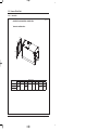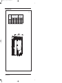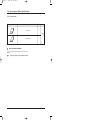
1
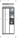
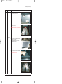
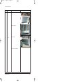
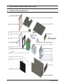
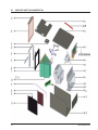
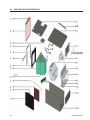
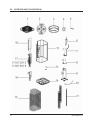
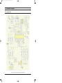
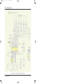
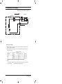
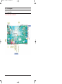
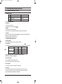
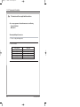
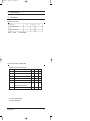
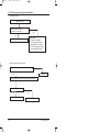
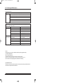
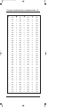
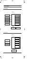
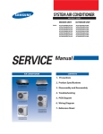
24524(1)_co
24524(1)_co
2/9/05
2/9/05 9:40
9:40 PM
PM
Page
Page 11
SYSTEM AIRCONDITIONER
Basic:INDOOR UNIT
Basic: FC36BTVA
Model : NS036DCRCA
NS048DCRCA
NS060DCRCA
Model Code : NS036DCRCA
NS048DCRCA
NS060DCRCA
SERVICE
AIR CONDITIONER
OUTDOOR UNIT
FC36BTVX
RC036FCRCA
RC048FCRCA
RC060FCRCA
RC036FCRCA
RC048FCRCA
RC060FCRCA
Manual
THE FEATURE OF PRODUCT
New design, more modern and elegant
appearance.
Convenient installation
Easy operation.
Low noise level plus compact size
NS036DCRCA
NS036FCRCA
RC048(60)DCRCA
RC048(60)FCRCA
For more information, Please access to our service web site (http://itself.sec.samsung.co.kr)
24524(1)_1
56/10/3 7:06 PM
Page 1
Contents
11. Precautions
..........................................................................................................................................
1-1
1-1 Installing the air conditioner .......................................................................................................... 1-1
...............................................................................................
1-1
................................................................................................................................
1-1
........................................................................................................................
1-2
....................................................................................................................................................
1-2
1-2 Power supply and circuit breaker
1-3 During operation
1-4 Disposing of the unit
1-5 Others
12. Product Specifications ............................................................................................................. 2-1
..................................................................................................................
2-1
...........................................................................................................................
2-2
2-1 The Feature of Product
2-2 Name of Each Part
2-3 Product Specifications .................................................................................................................... 2-4
2-4 Accessory and Option Specifications ....................................................................................... 2-6
13. Alignment and Adjustments
3-1 Test operation for adjustment
...............................................................................................
3-1
......................................................................................................
3-1
14. Disassembly and Reassembly
4-1 Indoor Unit
.........................................................................................
4-1
...........................................................................................................................................
4-1
........................................................................................................................................
4-4
4-2 Outdoor Unit
15. Exploded Views and Parts List ......................................................................................... 5-1
5-1 Indoor Unit
...........................................................................................................................................
5-1
........................................................................................................................................
5-5
5-2 Outdoor Unit
16. Electrical Parts List
.....................................................................................................................
6-1
................................................................................................................................
7-1
...........................................................................................................................................
7-1
........................................................................................................................................
7-2
17. Wiring Diagram
7-1 Indoor Unit
7-2 Outdoor Unit
18. Schematic Diagram
8-1 Indoor Unit
.....................................................................................................................
8-1
...........................................................................................................................................
8-1
........................................................................................................................................
8-2
8-2 Outdoor Unit
24524(1)_1
56/10/3 7:06 PM
Page 2
Contents
19. Refrigerating Cycle Diagram........................................................................................................ 9-1
9-1 Refrigerating Cycle Diagram ............................................................................................................... 9-1
10. PCB Diagram
10-1 Indoor Unit
......................................................................................................................................10-1
.........................................................................................................................................
10-1
.....................................................................................................................................
10-3
10-2 Outdoor Unit
11. Operating Instruction and Installation
11-1 Operating Modes and Function
11-2 Thermostat controler
12. Troubleshooting
12-1 Self-diagnosis
......................................................................11-1
....................................................................
...............................................................
11-1
11-3
..............................................................................................................................12-1
................................................................................................................
12-1
12-2 Solving Steps for Typical Malfunction ................................................................ 12-2
12-3 Servicing and Maintenace ............................................................................................... 12-4
12-4 Appendix
.........................................................................................................................
13. Block Diagram
13-1 Indoor Unit
..................................................................................................................................13-1
.........................................................................................................................................
13-2 Outdoor Unit
12-5
.....................................................................................................................................
13-1
13-1
14. Reference Sheet ..............................................................................................................................14-1
14-1 Index for Model Name
..................................................................................................................
14-1
14-2 Pressure & Capacity mark ........................................................................... 14-2
14-3 The abbreviated technology words & the definition of technology terms
14-4 Installation
...............
14-2
.........................................................................................................................................
14-3
24524(1)_1 56/10/3 7:06 PM Page 1-1
1. Precautions
1-1 Installing the air conditioner
Users should not install the air conditioner by themselves.
Ask the dealer or authorized company to install the air conditioner except the window-type air conditioner in U.S.A and Canada.
If you don’t install the air conditioner properly, it may cause a fire, a water leakage or an electric shock.
You must install the air conditioner according to the national wiring regulations and safety regulations.
Install the indoor unit higher than 2.5m from the floor to avoid the injury caused by the operation of the fan.
(except the window-type air conditioner)
The manufacturer is not responsible for any accidents or injury caused by an incorrect installation.
When installing the built-in type air conditioner, keep all electric cables such as the power cable and the connection cord in pipes,
ducts, or cable channels to protect them from the danger of impact or any other incidents.
1-2 Power supply and circuit breaker
If the power cord of the air conditioner is damaged, it must be replaced by the manufacturer or a qualified person in order to
avoid a hazard.
The air conditioner must be plugged into an independent circuit if applicable or connect the power cable to the auxiliary circuit
breaker.
An all pole disconnection from the power supply must be incorporated in the fixed wiring with a contact opening of >3mm.
Do not extend an electric cord to the air conditioner.
The air conditioner must be plugged in after you complete the installation.
1-3 During operation
Do not repair the air conditioner at your discretion.
It is recommended to contact a service center directly.
Never spill any kind of liquid on the air conditioner.
If this happens, turn off the air conditioner and contact an authorized service center.
Do not spray any kind of liquid into the indoor unit. If this happens,
turn off the air conditioner and contact a service center.
Samsung Electronics
1-1
1-3 During operation(cont.)
Do not place any obstacles top of the air conditioner.
Make sure that the air conditioner is well ventilated at all times:
Do not place a cloth or other materials over it.
Do not insert anything between the airflow blades to prevent damage
of the inner fan and consequent injury.
Keep children away from the air conditioner.
Remove the batteries if you don’t use the remote control
for a long time. (If applicable)
Use the remote control within 7 meters from the indoor unit.
(If applicable)
1-4 Disposing of the unit
When you dispose of the air conditioner, consult your dealer. If pipes are removed incorrectly, refrigerant may blow out and
cause air pollution. When it contacts with your skin, it can cause skin injury.
The package of the air conditioner should be recycled or disposed of properly for environmental reasons.
1-5 Others
Never store or load the air conditioner upside down or sideways to prevent the damage to the compressor.
Young children or infirm persons should be always supervised when they use the air conditioner.
Max current is measured according to IEC standard for safety.
Current is measured according to ISO standard for energy efficiency.
Samsung Electronics
1-2
24524(1 ) _1
56/1 0/ 3 7: 06 PM
Page 2- 1
2. Product Specifications
2-1 TheFeature of Product
Cabinet
That solid and galvanized steel construction, easy transport and installation, fully insulated and easy cleaning
helps to create a long run and healthy environment.
Motor
The high-efficiency motor performs durably. `
Coil
“A” style coil is adopting long-life rifled copper tubes, aluminum fin refrigerant coils, which helps to enhance
heat exchanger.
Filter
Factory installed filter can be cleaned and reinstalled for air filtration.
Drainage
Enhancing primary and second drainage design allows complete drainage to improve in-house air quality.
Throttle device
Using a changeable and durable piston as throttle device can guarantee the system operates reliably.
Protection
Factory installed coil temperature sensor providing effective protection of the system.
Application
Multiple airflow positions design, which includes up-flow, horizontal, enables an extensive share of the air
exchanged.
Performance
This series is designed and tested by ARI standard.
Samsung Electronics
2-1
2-2 Name of Each Part
2-2-1 IndoorUnit
(Unit : mm)
NS036DCRCA, NS048DCRCA, NS060DCRCA
Dimensions and Duct Sizes
3-1/4
H
C
3-1/4
3
D
B
16-3/8
E
1-1/8
A
G
F
Model
NS036DCRCA
NS048DCRCA
NS060DCRCA
2-2
Dimensions(inc es)
A(Height)
B(Depth)
C(Width)
39-3/8
47-1/4
D
18-1/8
20-1/2
21-1/4
8-1/4
E
h
11-1/4
F
1
G
H
16-1/8
11-5/8
19-1/4
14-2/5
Samsung Electronics
24524(1)_1
24524(1)_1
56/10/3
2/9/05 9:40
7:06 PM
PM Page
Page 2-3
2-2
2-2-2 Outdoor units
(Unit : mm)
Dimensions (mm)
Unit Model
Refrigerant
Connection Line
Size(mm)
Liquid(Ø) Vapor(Ø)
A
B
C
RC036FCRCA
840
554
554
12.7
19
RC048FCRCA
852
740
740
12.7
19
RC060FCRCA
852
740
740
12.7
19
Samsung Electronics
2-3
2-3 Product Specifications
Model
Power supply
Capacity
Input
Cooling
Rated current
EER
Capacity
Input
Heating
Rated current
COP
Max. input consumption
Max. current
Starting current
Model
Type
Brand
Supplier
Capacity
Input
Compressor
Rated current(RLA)
Locked rotor Amp
(LRA)
Thermal protector
Capacitor
Refrigerant oil
Model
Outdoor
fan Input
motor
Capacitor
Speed
Number of rows
Outdoor coil
Tube pitch(a)
Fins per inch
Fin type (code)
Tube outside dia.and type
V-Ph-Hz
Btu/h
W
A
Btu/w.h
Btu/h
W
A
Btu/w.h
W
A
A
Btu/h
W
A
A
uF
ml
W
uF
r/min
mm
inch
mm/inch
mm
Coil length x height x width inch
Number of circuits
3
m /h
Outdoor air flow
CFM
Outdoor noise level
dB(A)
Body(W*H*D)
mm
inch
Dimension
mm
Packing (W*H*D)
inch
lbs
Net/Gross weight
Kg
Refrigerant type
g
Design pressure
MPa
mm
Refrigerant
piping
Liquid side/ Gas side
inch
℃
Ambient temp
2
Application area
m
stuffing Qty (20'/40'/40HQ)
pieces
2-4
RC036FCRCA
208~230- 60-1
32000
3900
18.9
6.2
\
\
\
\
5180
28
130
C-SB261H6A
scroll
SANYO
SANYO
40600
3850
16.7
130
130
50
1700
YDK80-6M-1
172
6
920
1
25.4
1
14
unhydrophilic aluminum
9.52/ 3/8
inner groove tube
531X531X813
20-7/8 X20-7/8 X32
6
3300
1940
62
554X554X840
21-7/8 X21-7/8 X33-1/8
582X582X873
22-7/8 X22-7/8 X34-3/8
165/171.6
75/78
R22/1850
2.8
φ12.7/φ19
1/2 / 3/4
—7~45
42~70
80/160/238
RC048FCRCA
208~230- 60-1
48000
4680
22.3
8.1
\
\
\
\
5700
32
141
C-SB301H6B
scroll
SANYO
SANYO
49000
4550
21.7
RC060FCRCA
208~230- 60-1
52000
5500
25.6
7.4
\
\
\
\
6950
39
149
C-SB351H6A
scroll
SANYO
SANYO
57000
5390
24.4
141
130
50
1700
YDK165-6M
336
12
880
1
25.4
1
14
unhydrophilic aluminum
9.52/ 3/8
inner groove tube
713X713X813
20-7/8 X20-7/8 X32
6
4900
2881
65
740X852X740
29-1/8 X33-1/2 X29-1/8
770x770x890
30-3/8 X30-3/8 X35
202.4/213.4
92/97
R22/3000
2.8
φ12.7/φ19
1/2 / 3/4
—7~45
56~93
42/90/133
149
130
70
1700
YDK165-6M
336
12
880
1
25.4
1
14
unhydrophilic aluminum
9.52/ 3/8
inner groove tube
713X713X813
20-7/8 X20-7/8 X32
6
4900
2881
66
740X852X740
29-1/8 X33-1/2 X29-1/8
770x770x890
30-3/8 X30-3/8 X35
193.6/204.6
88/93
R22/3300
2.8
φ12.7/φ19
1/2 / 3/4
—7~45
64~100
42/90/133
Samsung Electronics
24524(1)_1
56/10/3 7:06 PM
Page 2-5
Specification
Model code(Indoor)
Power supply
NS036DCRCA
NS048DCRCA
NS060DCRCA
V-Ph-Hz
208-230V~ 60Hz,1Ph
208-230V~ 60Hz,1Ph
208-230V~ 60Hz,1Ph
Btu/h
34,500
48,000
55,500
Max. input consumption
W
5180
5700
6950
Max. current
A
28
32
39
Cooling Capacity
30
35
42
Model
YDK200-6X
YDK250-6X
YDK300-6X
Type
AC Motor
AC Motor
AC Motor
Brand
YongAn
YongAn
YongAn
Starting current
Indoor fan
motor
A
Input
W
495
500
655
Capacitor
uF
10
12
12
r/min
820/650
800/720
980/750
3
3
3
b.Tube pitch(a)x row pitch(b)
mm
25.4×22
25.4×22
25.4×22
c.Fin spacing
mm
1.8
1.8
1.8
Hydrophilic aluminium
Hydrophilic aluminium
Hydrophilic aluminium
φ9.52
φ9.52
φ9.52
innergroove tube
innergroove tube
innergroove tube
415x356x66
415x457x66
415x508x66
6
6
6
m3/h
2000/1530
2400/2100
2900/2180
Pa
50
100
100
dB(A)
54.4/50.8
52.6/50.1
56.9/51.3
Speed(hi/mi/lo)
a.Number of rows
Indoor coil
d.Fin type (code)
e.Tube outside dia.and type
mm
f.Coil length x height x width
mm
g.Number of circuits
Indoor air flow (Hi/Mi/Lo)
Indoor external static pressure (Hi)
Indoor noise level (Hi/Lo)
Indoor unit
Dimension (W*H*D)
mm
460x1000x520
540x1200x520
540x1200x520
Packing (W*H*D)
mm
515x1055x575
595x1255x575
595x1255x575
Net/Gross weight
Kg
51/56
61/66
65/70
g
R22
R22
R22
indoor side piston
indoor side piston
indoor side piston
MPa
2.8/1.2
2.8/1.2
2.8/1.2
mm
φ12.7/φ19
φ12.7/φ19
φ12.7/φ19
Max. refrigerant pipe length
m
30
30
30
Max. difference in level
m
10
10
10
mm2
3*1.0
3*1.0
3*1.0
Refrigerant type
Throttle type
Design pressure
Refrigerant
piping
Liquid side/ Gas side
Connection Power wiring
wiring
Signal wiring
mm2
Controller
6*1.0
6*1.0
6*1.0
remote controller
remote controller
remote controller
Operation temp
℃
17-30
17-30
17-30
Ambient temp
℃
T1
T1
T1
Application area
m2
42
56
70
Notes:
1. Nominal cooling capacities are based on the following conditions:
Indoor temp: 27°CDB, 19°CWB; Outdoor temp: 35°CDB; Equivalent ref. Piping: 5m(horizontal)
2. Nominal heating capacities are based on the following conditions:
Indoor temp: 20°CDB; Outdoor temp: 7°CDB, 6°CWB; Equivalent ref. Piping: 5m(horizontal)
3. Actual noise level may differ, depending on the room structure, etc, since these noise values are from an
anechoic room.
Samsung Electronics
2-5
24524(1)_1
56/10/3
7:06
PM
Page 2- 7
2-4 Accessory and Option Specifications
2-4-1 Accessories
Item
Descriptions
Q'TY
TIONS
OWNER'S INSTRUC CIONES
MANUAL DE INSTRUC
L'USO
ISTRUZIONI PER
ÕES
MANUAL DE INSTRUÇ
TION
MANUEL D'UTILISA
EISUNG
GEBRAUCHSANW
Air ConditionerSplit
Splut-type Room
doméstico sistema
ad unità Separate
Aire acondicionado
d'aria per ambienti
Condizionatorede ar condicionado tipo Split
Aparelho
type séparé
Climatiseur de
Geteilte raumklimaanlage
Owner’s manual
Remark
1
Indoor
Unit
TIONS
OWNER'S INSTRUC CIONES
MANUAL DE INSTRUC
L'USO
ISTRUZIONI PER
ÕES
MANUAL DE INSTRUÇ
TION
MANUEL D'UTILISA
EISUNG
GEBRAUCHSANW
Air ConditionerSplit
Splut-type Room
doméstico sistema
ad unità Separate
Aire acondicionado
d'aria per ambienti
Condizionatorede ar condicionado tipo Split
Aparelho
type séparé
Climatiseur de
Geteilte raumklimaanlage
Installation manual
1
Cautions on Controller Installation
Choose Non-programmed electrical thermostat series of Honeywell, such as
Th5220D.
Note
The thermostat controller is not supplied with the air conditioner.
Samsung Electronics
2-6
24524(1)_1
24524(
1) _1
56/10/3
56/ 10/ 3 7:06
7: 06 PM
Page 2- 8
3. Alignmentand Adjustments
3-1. Test operation for adjustment
(1) The test operation must be carried out after the entire ins tallation has been completed.
(2) Please confirm the following poin ts before the test operation.
The indoor unit and outdoor unit are installed properly.
Tubing and wiring are correctly completed.
The refrigerant pipe system is leakage-checked.
The drainage is unimpeded.
The ground wiring is connected correctly.
The length of the tubing and the added stow capacity of the refrigerant have been recoded
The power voltage fits the rated voltage of the air conditioner.
There is no obstacle at the outlet and inlet of the outdoor and indoor units.
The gas-side and liquid-side stop values are both opened.
The air conditioner is pre-heated by turning on the power.
(3) According to the user's requirement, install the controller
(4) Test operation
Indoor unit
Whether the switch on the controller works well.
Whether the buttons on the controller works well.
Whether the air flow is normally.
Whether the room temperature is adjusted well.
Whether the indicator lights normally.
Whether the drainage is normal.
Whether there is vibration or abnormal noise during operation.
3-1
Samsung Electronics
24121A(1)_ 1
1/28/0 5 6:1 8 AM
Page 3- 6
4. Disassembly and Reassembly
Stop operation of the air conditioner and remove the power cord before repairing the unit.
4-1 Indoor Unit (NS036DCRCA, NS048DCRCA, NS060DCRCA)
No
Parts
Procedure
1
Electrical
Part
1) Loosen the 4 screws, open the front cover
Remark
2) Loosen the 5 screws, open the top cover
3) Move the front and top cover
Be careful cut off power supply before
you move the cove
Samsung Electronics
4-1
24121A(1)_ 1
1/28/0 5 6:1 8 AM
Page 3- 7
Disassembly and Reassembly
No
Parts
Procedure
Remark
1) Loosen screws, open the cover
2) Move the front cover
Be careful don’t destroy the connective pipe
2
Evaporator
3) Loosen screws and Move the sheet metal,
then take out the filter.
The operation instruction please refer to
filter disassembly step
4) Loosen screws and take out the evaporator
Be careful your hand
4-2
Samsung Electronics
24121A(1)_1
1/28/05
6:18
AM
Page 3- 8
Disassembly and Reassembly
No
Parts
Procedure
Remark
1) Loosen the 2 screws
2) Move the sheet metal
3
Filter
3) Take out the filter
4
4) You can wash it and reassembly
Samsung Electronics
4-3
24121A(1)_ 1
1/28/0 5 6:1 8 AM
Page 3- 15
4-2 Outdoor Unit (RC036FCRCA, RC048FCRCA, RC060FCRCA)
No
Parts
1
Cabinet
Procedure
Remark
1) Turn off the unit and remove the Power
Cable.
2) Detach the Top Cover.
3) Detach the Control Box Cover.
4) Unplug the Ass'y Cable.
5) Detach the Cabi-Side.
6) Detach the Cabi-Front.
When you assemble the parts, check
the each parts and component
Electric Box are fixed firmly.
2
Fan Motor
&
Propeller Fan
Samsung Electronics
1) Loosen the indicating bolt screw.
2) Disassemble the Propeller Fan.
4-4
5. EXPLODED VIEWS AND PARTS LIST
5-1 INDOOR UNIT (NS036DCRCA)
5-1
SamsungElectronics
•
PART LIST
No.
Part Name
OEM code
Quantity
SA/SNA
1
A/S ASSY-UNDERSIDE BOARD
DB82-01037A
1
SA
2
A/S ASSY-UPSIDE BOARD
DB82-01038A
1
SA
3
A/S ASSY-ELECTRONIC CONTROL BOX
DB82-01039A
1
SA
3.1
AS-POLE
DB81-02386A
4
SA
3.2
A/S ASSY-MAIN CONTROL BOARD
DB82-01028A
1
SA
3.3
AS-24V AC TRANSFORMER
DB81-02364A
1
SA
3.4
AS-TRANSFORMER
DB81-02365A
1
SA
3.5
AS-GROUNDING TERMINAL
DB81-02366A
1
SA
3.6
AS-WIRE JOINT
DB81-02367A
1
SA
3.7
AS-FAN MOTOR CAPACITOR
DB81-02387A
1
SA
4
AS-ASYNCHRONOUS MOTOR
DB81-02388A
1
SA
5
A/S ASSY-FAN
DB82-01040A
1
SA
6
AS-TOP WIND BAFFLE BOARD
DB81-02389A
1
SA
7
AS-LEFT WIND BAFFLE BOARD
DB81-02390A
1
SA
8
AS-WIND BAFFLE BOARD
DB81-02391A
1
SA
9
AS-BOTTOM WIND BAFFLE BOARD
DB81-02392A
1
SA
10
AS-RIGHT WIND BAFFLE BOARD
DB81-02393A
1
SA
11
AS-SUPPORTER OF AIR PASSAGE
DB81-02394A
1
SA
12
A/S ASSY-UP FRONT BOARD
DB82-01041A
1
SA
13
A/S ASSY-CHASSIS
DB82-01042A
1
SA
14
AS-WATER COLLECTOR
DB81-02395A
1
SA
15
AS-SEAL STOPPER
DB81-02368A
4
SA
16
A/S ASSY-PIPE TEMPERATURE SENSOR
DB82-01029A
1
SA
17
A/S ASSY-EVAPORATOR
DB82-01043A
1
SA
A/S ASSY-INPUT PIPE
DB82-01044A
1
SA
AS-THROTTLE DISTRIBUTOR
DB81-02396A
1
SA
18
AS-WATER COLLECTOR
DB81-02397A
1
SA
19
AS-FIX BOARD OF WATER COLLECTOR
DB81-02369A
1
SA
20
AS-SUPPORTER OF WATER COLLECTOR
DB81-02370A
2
SA
21
AS-UNDERSIDE SUPPORTING BOARD
DB81-02398A
1
SA
22
A/S ASSY-COVER BOARD
DB82-01030A
1
SA
23
AS-AIR FILTER
DB81-02399A
1
SA
24
AS-AIR FILTER SHUTTER
DB81-02400A
1
SA
17.1
17.1.1
SamsungElectronics
5-2
5-1 INDOOR UNIT (NS048DCRCA)
5-3
SamsungElectronics
•
PART LIST
No.
Part Name
OEM code
Quantity
SA/SNA
1
A/S ASSY-UNDERSIDE BOARD
DB82-01031A
1
SA
2
A/S ASSY-UPSIDE BOARD
DB82-01032A
1
SA
3
A/S ASSY-ELECTRONIC CONTROL BOX
DB82-01033A
1
SA
3.1
AS-POLE
DB81-02371A
4
SA
3.2
A/S ASSY-MAIN CONTROL BOARD
DB82-01028A
1
SA
3.3
AS-24V AC TRANSFORMER
DB81-02364A
1
SA
3.4
AS-TRANSFORMER
DB81-02365A
1
SA
3.5
AS-GROUNDING TERMINAL
DB81-02366A
1
SA
3.6
AS-WIRE JOINT
DB81-02367A
1
SA
3.7
AS-COMPRESSOR CAPACITOR
DB81-02372A
1
SA
4
AS-ASYNCHRONOUS MOTOR
DB81-02401A
1
SA
5
A/S ASSY-FAN
DB82-01034A
1
SA
6
AS-TOP WIND BAFFLE BOARD
DB81-02373A
1
SA
7
AS-LEFT WIND BAFFLE BOARD
DB81-02374A
1
SA
8
AS-BOTTOM WIND BAFFLE BOARD
DB81-02375A
1
SA
9
AS-RIGHT WIND BAFFLE BOARD
DB81-02377A
1
SA
10
AS-SUPPORTER OF AIR PASSAGE
DB81-02376A
2
SA
10
AS-SUPPORTER OF AIR PASSAGE
DB81-02378A
1
SA
11
A/S ASSY-UP FRONT BOARD
DB82-01035A
1
SA
12
A/S ASSY-CHASSIS
DB82-01036A
1
SA
13
AS-WATER COLLECTOR
DB81-02379A
1
SA
14
AS-SEAL STOPPER
DB81-02368A
4
SA
15
AS-WATERPROOF BOARD
DB81-02380A
1
SA
16
A/S ASSY-PIPE TEMPERATURE SENSOR
DB82-01029A
1
SA
17
A/S ASSY-EVAPORATOR
DB82-01045A
1
SA
A/S ASSY-INPUT PIPE
DB82-01046A
1
SA
AS-THROTTLE DISTRIBUTOR
DB81-02402A
1
SA
18
AS-WATER COLLECTOR
DB81-02381A
1
SA
19
AS-FIX BOARD OF WATER COLLECTOR
DB81-02369A
1
SA
20
AS-SUPPORTER OF WATER COLLECTOR
DB81-02370A
2
SA
21
AS-UNDERSIDE SUPPORTING BOARD
DB81-02382A
1
SA
22
A/S ASSY-COVER BOARD
DB82-01030A
1
SA
23
AS-AIR FILTER
DB81-02383A
1
SA
24
AS-AIR FILTER SHUTTER
DB81-02384A
1
SA
26
AS-UPSIDE SUPPORTER BOARDING
DB81-02385A
1
SA
17.1
17.1.1
SamsungElectronics
5-4
5-1 INDOOR UNIT (NS060DCRCA)
5-5
SamsungElectronics
•
PART LIST
No.
Part Name
OEM code
Quantity
SA/SNA
1
A/S ASSY-UNDERSIDE BOARD
DB82-01031A
1
SA
2
A/S ASSY-UPSIDE BOARD
DB82-01032A
1
SA
3
A/S ASSY-ELECTRONIC CONTROL BOX
DB82-01033A
1
SA
3.1
AS-POLE
DB81-02371A
4
SA
3.2
A/S ASSY-MAIN CONTROL BOARD
DB82-01028A
1
SA
3.3
AS-24V AC TRANSFORMER
DB81-02364A
1
SA
3.4
AS-TRANSFORMER
DB81-02365A
1
SA
3.5
AS-GROUNDING TERMINAL
DB81-02366A
1
SA
3.6
AS-WIRE JOINT
DB81-02367A
1
SA
3.7
AS-COMPRESSOR CAPACITOR
DB81-02372A
1
SA
4
AS-ASYNCHRONOUS MOTOR
DB81-02403A
1
SA
5
A/S ASSY-FAN
DB82-01034A
1
SA
6
AS-TOP WIND BAFFLE BOARD
DB81-02373A
1
SA
7
AS-LEFT WIND BAFFLE BOARD
DB81-02374A
1
SA
8
AS-BOTTOM WIND BAFFLE BOARD
DB81-02375A
1
SA
9
AS-RIGHT WIND BAFFLE BOARD
DB81-02377A
1
SA
10
AS-SUPPORTER OF AIR PASSAGE
DB81-02376A
2
SA
10
AS-SUPPORTER OF AIR PASSAGE
DB81-02378A
1
SA
11
A/S ASSY-UP FRONT BOARD
DB82-01035A
1
SA
12
A/S ASSY-CHASSIS
DB82-01036A
1
SA
13
AS-WATER COLLECTOR
DB81-02379A
1
SA
14
AS-SEAL STOPPER
DB81-02368A
4
SA
15
AS-WATERPROOF BOARD
DB81-02380A
1
SA
16
A/S ASSY-PIPE TEMPERATURE SENSOR
DB82-01029A
1
SA
17
A/S ASSY-EVAPORATOR
DB82-01047A
1
SA
A/S ASSY-INPUT PIPE
DB82-01048A
1
SA
AS-THROTTLE DISTRIBUTOR
DB81-02404A
1
SA
18
AS-WATER COLLECTOR
DB81-02381A
1
SA
19
AS-FIX BOARD OF WATER COLLECTOR
DB81-02369A
1
SA
20
AS-SUPPORTER OF WATER COLLECTOR
DB81-02370A
2
SA
21
AS-UNDERSIDE SUPPORTING BOARD
DB81-02382A
1
SA
22
A/S ASSY-COVER BOARD
DB82-01030A
1
SA
23
AS-AIR FILTER
DB81-02383A
1
SA
24
AS-AIR FILTER SHUTTER
DB81-02384A
1
SA
26
AS-UPSIDE SUPPORTER BOARDING
DB81-02385A
1
SA
17.1
17.1.1
SamsungElectronics
5-6
5-2 OUTDOOR UNIT (RC036FCRCA)
5-7
SamsungElectronics
•
PART LIST
No.
Part Name
OEM code
Quantity
SA/SNA
1
A/S ASSY-TOP COVER
DB82-01003A
1
SA
2
AS-AXIAL FLOW FAN
DB81-02332A
1
SA
3
AS-VENTILATION RING
DB81-02335A
1
SA
4
AS-ASYNCHRONOUS MOTOR
DB81-02336A
1
SA
5
AS-WIRE GUIDE PIPE
DB81-02338A
1
SA
6
AS-DISCHARGE PIPE
DB81-02339A
1
SA
7
A/S ASSY-GAS VALVE
DB82-01004A
1
SA
AS-VALVE BODY
DB81-02340A
1
SA
A/S ASSY-LIQUID VALVE
DB82-01011A
1
SA
AS-VALVE BODY
DB81-02341A
1
SA
9
AS-COMPRESSOR
DB81-02349A
1
SA
10
A/S ASSY-COMPRESSOR WIRE
DB82-01005A
1
SA
11
AS-SUPPORTING BOARD
DB81-02352A
3
SA
12
A/S ASSY-CONDENSER
DB82-01006A
1
SA
13
AS-NON SLIP PADS 1
DB81-02355A
2
SA
14
A/S ASSY-CHASSIS
DB82-01007A
1
SA
15
AS-REAR NET
DB81-02356A
1
SA
16
A/S ASSY-UNDERSIDE BOARD
DB82-01008A
1
SA
17
A/S ASSY-ELECTRONIC CONTROL BOX
DB82-01009A
1
SA
17.1
AS-INSTALL PLATE OF ELECTRIC PART
DB81-02360A
1
SA
17.2
A/S ASSY-E-PART BOX INSTALL BOARD
DB82-01010A
1
SA
17.3
AS-AC CONTACTOR
DB81-02342A
1
SA
17.4
AS-COMPRESSOR CAPACITOR
DB81-02347A
1
SA
17.5
AS-WIRE JOINT
DB81-02343A
1
SA
17.5
AS-WIRE JOINT
DB81-02344A
1
SA
17.6
AS-FAN MOTOR CAPACITOR
DB81-02359A
1
SA
17.7
A/S ASSY-E-PART BOX INSTALL BOARD
DB82-01010A
1
SA
AS-SIDE BOARD
DB81-02346A
1
SA
7.1
8
8.1
18
SamsungElectronics
5-8
5-2 OUTDOOR UNIT (RC048FCRCA)
5-9
SamsungElectronics
•
PART LIST
No.
Part Name
OEM code
Quantity
SA/SNA
1
A/S ASSY-TOP COVER
DB82-01012A
1
SA
2
AS-AXIAL FLOW FAN
DB81-02333A
1
SA
3
AS-VENTILATION RING
DB81-02334A
1
SA
4
AS-ASYNCHRONOUS MOTOR
DB81-02337A
1
SA
5
AS-WIRE GUIDE PIPE
DB81-02476A
1
SA
6
A/S ASSY-DISCHARGE PIPE
DB82-01014A
1
SA
8
A/S ASSY-GAS VALVE
DB82-01015A
1
SA
AS-VALVE BODY
DB81-02340A
1
SA
A/S ASSY-LIQUID VALVE
DB82-01011A
1
SA
9.1
AS-VALVE BODY
DB81-02341A
1
SA
10
AS-COMPRESSOR
DB81-02350A
1
SA
11
A/S ASSY-COMPRESSOR WIRE
DB82-01016A
1
SA
12
AS-SUPPORTING BOARD
DB81-02353A
3
SA
13
A/S ASSY-CONDENSER
DB82-01017A
1
SA
15
A/S ASSY-CHASSIS
DB82-01013A
1
SA
16
AS-REAR NET
DB81-02357A
1
SA
17
A/S ASSY-UNDERSIDE BOARD
DB82-01018A
1
SA
18
AS-SIDE BOARD
DB81-02346A
1
SA
19
A/S ASSY-ELECTRONIC CONTROL BOX
DB82-01019A
1
SA
19.1
AS-INSTALL PLATE OF ELECTRIC PART
DB81-02361A
1
SA
19.2
AS-INSTALL PLATE OF ELECTRIC PART
DB81-02362A
1
SA
19.3
AS-AC CONTACTOR
DB81-02342A
1
SA
19.4
AS-WIRE JOINT
DB81-02343A
1
SA
19.4
AS-WIRE JOINT
DB81-02344A
1
SA
19.5
AS-COMPRESSOR CAPACITOR
DB81-02347A
1
SA
19.5
AS-COMPRESSOR CAPACITOR
DB81-02345A
1
SA
8.1
9
SamsungElectronics
5-10
5-2 OUTDOOR UNIT (RC060FCRCA)
5-11
SamsungElectronics
•
PART LIST
No.
Part Name
OEM code
Quantity
SA/SNA
1
A/S ASSY-TOP COVER
DB82-01012A
1
SA
2
AS-AXIAL FLOW FAN
DB81-02333A
1
SA
3
AS-VENTILATION RING
DB81-02334A
1
SA
4
AS-ASYNCHRONOUS MOTOR
DB81-02337A
1
SA
5
AS-WIRE GUIDE PIPE
DB81-02476A
1
SA
6
A/S ASSY-DISCHARGE PIPE
DB82-01020A
1
SA
8
A/S ASSY-GAS VALVE
DB82-01021A
1
SA
AS-VALVE BODY
DB81-02340A
1
SA
A/S ASSY-LIQUID VALVE
DB82-01011A
1
SA
9.1
AS-VALVE BODY
DB81-02341A
1
SA
10
AS-COMPRESSOR
DB81-02351A
1
SA
11
A/S ASSY-COMPRESSOR WIRE
DB82-01022A
1
SA
12
AS-SUPPORTING BOARD
DB81-02354A
3
SA
13
A/S ASSY-CONDENSER
DB82-01023A
1
SA
15
A/S ASSY-CHASSIS
DB82-01013A
1
SA
16
AS-REAR NET
DB81-02358A
1
SA
17
A/S ASSY-UNDERSIDE BOARD
DB82-01024A
1
SA
18
AS-SIDE BOARD
DB81-02346A
1
SA
19
A/S ASSY-ELECTRONIC CONTROL BOX
DB82-01025A
1
SA
19.1
AS-INSTALL PLATE OF ELECTRIC PART
DB81-02361A
1
SA
19.2
AS-INSTALL PLATE OF ELECTRIC PART
DB81-02363A
1
SA
19.3
AS-AC CONTACTOR
DB81-02342A
1
SA
19.4
AS-WIRE JOINT
DB81-02343A
1
SA
19.4
AS-WIRE JOINT
DB81-02344A
1
SA
19.5
AS-COMPRESSOR CAPACITOR
DB81-02347A
1
SA
19.5
AS-COMPRESSOR CAPACITOR
DB81-02348A
1
SA
8.1
9
SamsungElectronics
5-12
24121A(1)_1
1/28/05 6:18 AM
Page 6-1
6. Electrical Parts List
This products don’t supply elecrical part list(OEM model)
Samsung Electronics
6-1
24524(1)_ 1
56/10/ 3 7:0 8 PM
Page 4- 18
7. Wiring Diagram
7-1 Indoor Unit
NS036DCRCA, NS048DCRCA,NS060DCRCA
This Document can not be used without Samsung's authorization.
7-1
Samsung Electronics
24524(1)_ 1
56/10/ 3 7:0 8 PM
Page 4- 19
7-2 Outdoor Unit
RC036(48)FCRCA
This Document can not be used without Samsung's authorization.
Samsung Electronics
7-2
24524(1)_1
56/10/3 7:08 PM
Page 4-19
7-2 Outdoor Unit
RC060FCRCA
This Document can not be used without Samsung's authorization.
7-3
Samsung Electronics
24524(1)_1
56/10/3 7:08 PM
Page 4-20
8. Schematic Diagram
8-1 Indoor Unit
This Document can not be used without Samsung's authorization.
8-1
Samsung Electronics
24524(1)_1
56/10/3 7:08 PM
Page 4-21
8-2 Outdoor Unit
This Document can not be used without Samsung's authorization.
Samsung Electronics
8-2
24524(1)_ 1
56/10/ 3 7:0 9 PM
Page 4- 26
9. Refrigerating cycle diagram
*Allowable pipe length : AC36BTV, AC48BTV Max. 25m, AC60BTV Max. 30m
*Allowable drop distance : AC36BTV, AC48BTV Max.10m, AC60BTV Max. 15m
Indoor unit
Direction of refrigerant flow
Outdoor unit
Throttle Orifice
T2 evaporator temp. sensor
T1
room temp. sensor
compressor
Additional charge
1). When the length of the one-way pipe is less than 5m, additional refrigerant charge
after vacuuming is unnecessary.
2). When the length of one-way pipe is over 5m, the additional charge quantity is as
follows (unit in gram):
Calculation method
Refrigerant
R22
Liquid
mm
diameter
Unit amount (g/m)
Formula
Φ6.35
30
(L-5)× 30
Φ9.53
65
(L-5)× 65
Φ12.7
90
(L-5)× 90
Remark.
1. The additional refrigerant charge is simply related with the liquid pipe diameter
2. In the up formula, “ L”
9-1
means total length of liquid pipe(unit: m)
Samsung Electronics
24524(1)_1
56/10/3
7:09
PM
Page 4-2 8
10. PCB Diagram
10-1 Indoor Unit
Indoor PCB of NS36, 48, 60DCRCA
10-1
Samsung Electronics
10-2 Outdoor Unit
Outdoor PCB of RC036FCRCA
4
1
6
5
2
1
5
Trans out
24V to indoor
2
Hi/low pressur s/w
6
3
Temp sensor
7
4
10-2
Power input
3
Trans In
Samsung Electronics
24524(1)_1
56/10/3
7:09
PM
Page 4-3 2
11. Operating Instruction and Installation
11-1 Operation Modes and Function
1.1 Performance Index
No.
Item
Index
1
Applicable Voltage Range
175~253V
2
A/C Frequency
60Hz/50Hz
3
Working environment temperature
-7℃~+43℃(19.4℉~109.4℉)
※ Cooling only : 21~43℃(Outdoor temp)
1.2 Main Parts Introduction
1.2.1 Indoor Fan
.
Indoor fan has only one speed.
Breeze speed only for anti-cold air in heating mode
machine.
1.2.2 Buzzer
2.2.1 It will buzz 2 times when electrifying the
2.2.2 It will buzz once for 0.3 second when receiving the remote signal or other valid signal.
1.2.3 Indicator
2.3.1 There are 4 indicators: operating indicator, timer indicator, warning indicator, defrosting/pre-heating
indicator (fan only indicator for cooling-only A/C). ctive.
2.3.2 LED indicates errors when protection is effe
1.3. Operation Modes and Functions
1.3.1 Manual Operation
1.3.1.1 The manual operation mode is not provided in AHU indoors.
1.3.2 Cooling Mode
1.3.2.1 Conditions for the compressor and outdoor fan action (Ts = set temperature, Ta=room temperature)
Room temp. up
Room temp. down
Condition
Ta > Ts+1
Ta <Ts+1
Ta > Ts
Ta <Ts
Compressor
On
Off
On
Off
Outdoor fan
On
Off
On
Off
1.3.3 Heating Mode (This function is not avaluable in cooling only models)
1.3.4 Defrost (only available to heating mode)
1.3.5 Dehumidifying Mode
1.3.5.1 Dehumidifying mode is the cooling operation.
1.3.5.2 Protective functions are the same as the cooling mode.
1.3.6 Fan Only Mode
1.3.6.1 Under this mode compressor and outdoor fan are shut down.
1.3.7 Auto Mode
1.3.7.1 Selected by controler. Under this mode, temperature can be set between 17 and 30°C.
1.3.7.2 When entering auto mode, fan only or cooling operation will be chosen according to the
room temperature Ta and the set temperature Ts automatically.
Samsung Electronics
11-1
24524(1)_ 1
56/10/ 3 7:0 9 PM
Page 4- 34
1.4. Other Functions
1.4.1 LED Display
AHU has only pipe temp sensor. And wired controler input signal for error code.
1.4.2 Timer
Refer to wired controller manual for detail operation.
Note: The timer is valid for one operation of the A/C.
1.5. Protection
1.5.1 Three-minute delay for the compressor start-up.
At the beginning of energizing, 1-minute will be needed to start the compressor. If the compressor stops
during the operating process (including the switchover between cooling, dehumidifying and heating mode),
3-minute delay will be needed to restart the compressor.
1.5.2 Evaporator protection against high temperature (heating mode)
2.1.4 Evaporator Prote ction agains t low tempe rature(cooli ng mode)
2.1.4.1 When the evaporator pipe temperature ≤ 3°c and this lasts for 3 minutes, the compressor and
outdoor fan will be shut off.
2.1.4.2 When the evaporator pipe temperature ≥ 7°c, it recovers.
2.1.4.3 The restart of the compressor shall execute the delay protection.
2.1.5 Anti-cold air prot ection
Only available to heating mode, including heating mode, heating operation under auto mode.
2.1.6 Condenser high temperature protection
2.1.6.1Only available to cooling
2.1.6.2 Delay protection should be performed when the compressor restarts.
2.1.7 Outdoor protection
When outdoor protection happen, system will stop running and LED display corresponding contents.(as the
following part referred)
2.1.8 Power supp ly electricity sequence protect ion
1. For 1 phase unit it owns a starting circuit. 1 second before startup, capacitor is switched on and then
broken.
2. For 3 phase unit it must have the phase sequence and lacking of phase checking and protecting function.
Etc.
3. System precision
1) Temperature sampling precision: ±1℃
2) Current sampling precision: ±1.5 amps
3) Timing sampling precision: ±1min/hour
4) Swing angle sampling precision: 0.7 degree
11-2
Samsung Electronics
24524(1)_1
56/10/3
7:09
PM
Page 4-3 7
11-2 Thermostat Controller
The thermostat controller is not supplied with the air conditioner.
Note
Choose non-programmed electrical thermostat series as following
- Honeywell, TH5220D
- Hailin, A3211
Thermostat(holleywell) connection
1
Choose cooling and heating model.
2
Note Connection.
Rooftop Package
R
CR
G
Y
W1/0/B
11-3
Thermostat
R
C
G
Y
B
Samsung Electronics
24524(1)_1
56/10/3
7:09
PM
Page 4-3 8
12. Trouble shooting
12-1 Self-di agnosis
(1) Indoor unit ’s LED indication
NO.
Malfunction
LED1
LED2
LED3
1
Indoor temp. sensor error
☆
×
×
2
Wire control input error
☆
×
☆
Note: ×—— LED off , ☆——LED flash quickly
(2) LEDs’ for the indication of outdoor trouble
This table is only suitable for the modles with PCB.
Type
Item
LED1
LED2
LED3
Malfunction
Phase sequence
Flash
Off
Off
Malfunction
Low pressure protection
Flash
Flash
Off
Malfunction
Current protection
Off
Off
Flash
Malfunction
Communication malfunction
Flash
Off
Flash
Malfunction
T3 open circuit, short circuit malfunction
Off
Flash
Flash
Malfunction
T4 open circuit, short circuit malfunction Off
(Compressor discharge protection)
Flash
Off
Malfunction
Condenser high temperature protection
Flash
Flash
Flash
Remarks: It means the system in the stand-by when the LED1-LED3 lights flash slowly.
T3: Outdoor condenser’s temperature
T4: Outdoor ambient temperature
Samsung Electronics
12-1
24524(1)_1
56/10/3
7:10
PM
Page 4-4 3
12-2 Solving steps for typical malfunction
a. Overload of current
Overload of current
Check the current, normally
Is the current in rated range?
No
Yes
Possible reason
1. Outdoor fan is defective
2. The compressor is defective
3. Refrigerant is over charged
4. Air enter the refrigerant system
5. Heat exchanger is too dirty
The outdoor PCB is defective
b. Open-circuit and short-circuit trouble
Is connection to connector of temp. sensor
good?
No
Yes
Repair connector
Check the resistance of the temp. sensor according to Annex 1
Is it the resistance is normal?
Yes
Indoor PCB is defective.
12-2
No
Replace the sensor
Samsung Electronics
24524(1)_ 1
56/10/ 3 7:0 9 PM
Page 4- 39
Troubleshooting
c. Open-circuit and short-circuit trouble
Is connection to connector of temp. sensor
good?
No
Yes
Check the resistance of the temp. sensor according to Annex 1
Repair connector
Is it the resistance is normal?
No
Yes
Indoor PCB is defective.
Replace the sensor
d. High temperature protection of condenser
High temperature protection of condenser
Check the resistance of the temp. sensor
according to Annex 1, is it normal?
Yes
Possible reason
1. Air or other gas in the refrigerant.
2. Heat exchanger is dirty
3. Outdoor fan or fan blade is
defective
4. Outdoor unit is bad ventilation
5. Refrigerant is leakage
No
Replace the sensor
e. Wire control input error
Check the Volt between C and G wire on the indoor PCB, is it 24 V?
Yes
Replace the indoor PCB
12-3
No
Replace the wire controller.
Samsung Electronics
24524(1) _1
56/10 / 3 7: 10 PM
Page 4- 43
12-3 Servicing and Maintenance
1) Troubles and Solutions
If any the following abnormal conditions occur, turn off the power supply immediately. Please contact our dealer.
TROUBLES
Indicator lamps flash rapidly, after your disconnecting and connecting the unit, the situation is the same.
Fuse or circuit breaker work frequently.
Foreign matter or water has fallen into the unit.
controller is disabled or the switch is out of hand.
Any other unusual conditioner is observed.
If any of the following conditions occur, check your unit and resolve corresponding problems referring to given remediation. If
the trouble can't be settled contact our dealer.
Trouble
Unit does not start
Cause
Solutions
Power failure.
Wait for the comeback of power
Power switch is open.
Switch on the power
Fuse of power switch may have blown.
Replace the fuse
The time is not start-up time you have set.
Wait or cancel the time set.
Air flowing normally
Temperature is not set correctly.
Set the temperature properly.
with low cooling effect
Door or window is open.
Close door and window.
Air filter is blocked with dust or dirtiness.
Clean the air filter.
Inlet/outlet of indoor/outdoor units are blocked.
Clear all blockages.
Inlet/outlet of indoor/outdoor units are blocked.
Clear the blockage, then restart your operation.
Be in 3 minutes protection of compressor
Wait
NOTE: Do not replace electric wire or repair the air conditioner by yourself to avoid possible danger.
2) Clean
CAUTION: Please turn off your air conditioner and disconnect power supply before cleaning.
(1) CLEANING INDOOR UNIT
Use a dry to wipe the indoor unit.
A cloth dampened with cold water may be used if the indoor unit is too dirty.
Note: Do not use a chemically treated duster for wiping or leave such materials near the unit for long.
Do not use benzene, thinner, polishing powder, or similar solvents for cleaning.
(2) CLEANING AIR FILTER
The air filter in unit can filter dust and other granules in air. It may reduce the cooling effect that the air filter is
covered with dust. So please clean the air filter often.
Samsung Electronics
12-4
24524(1)_1
56/10/3 7:10 PM
Page 4-43
12-4 Appendix IndoorTemp. and Pipe Temp. Sensor Resistance Value Table (C --K)
℃
K Ohm
℃
K Ohm
℃
K Ohm
℃
K Ohm
-20
115.266
20
12.6431
60
2.35774
100
0.62973
-19
108.146
21
12.0561
61
2.27249
101
0.61148
-18
101.517
22
11.5000
62
2.19073
102
0.59386
-17
96.3423
23
10.9731
63
2.11241
103
0.57683
-16
89.5865
24
10.4736
64
2.03732
104
0.56038
-15
84.2190
25
10.000
65
1.96532
105
0.54448
-14
79.3110
26
9.55074
66
1.89627
106
0.52912
-13
74.5360
27
9.12445
67
1.83003
107
0.51426
-12
70.1698
28
8.71983
68
1.76647
108
0.49989
-11
66.0898
29
8.33566
69
1.70547
109
0.48600
-10
62.2756
30
7.97078
70
1.64691
110
0.47256
-9
58.7079
31
7.62411
71
1.59068
111
0.45957
-8
56.3694
32
7.29464
72
1.53668
112
0.44699
-7
52.2438
33
6.98142
73
1.48481
113
0.43482
-6
49.3161
34
6.68355
74
1.43498
114
0.42304
-5
46.5725
35
6.40021
75
1.38703
115
0.41164
-4
44.0000
36
6.13059
76
1.34105
116
0.40060
-3
41.5878
37
5.87359
77
1.29078
117
0.38991
-2
39.8239
38
5.62961
78
1.25423
118
0.37956
-1
37.1988
39
5.39689
79
1.21330
119
0.36954
0
35.2024
40
5.17519
80
1.17393
120
0.35982
1
33.3269
41
4.96392
81
1.13604
121
0.35042
2
31.5635
42
4.76253
82
1.09958
122
0.3413
3
29.9058
43
4.57050
83
1.06448
123
0.33246
4
28.3459
44
4.38736
84
1.03069
124
0.32390
5
26.8778
45
4.21263
85
0.99815
125
0.31559
6
25.4954
46
4.04589
86
0.96681
126
0.30754
7
24.1932
47
3.88673
87
0.93662
127
0.29974
8
22.5662
48
3.73476
88
0.90753
128
0.29216
9
21.8094
49
3.58962
89
0.87950
129
0.28482
10
20.7184
50
3.45097
90
0.85248
130
0.27770
11
19.6891
51
3.31847
91
0.82643
131
0.27078
12
18.7177
52
3.19183
92
0.80132
132
0.26408
13
17.8005
53
3.07075
93
0.77709
133
0.25757
14
16.9341
54
2.95896
94
0.75373
134
0.25125
15
16.1156
55
2.84421
95
0.73119
135
0.24512
16
15.3418
56
2.73823
96
0.70944
136
0.23916
17
14.6181
57
2.63682
97
0.68844
137
0.23338
18
13.9180
58
2.53973
98
0.66818
138
0.22776
19
13.2631
59
2.44677
99
0.64862
139
0.22231
Samsung Electronics
12-5
24524(1)_1 56/10/3 7:10 PM Page 13-1
13. Block Diagram
13-1 Indoor Unit
Indoor unit
Display
Indoor Fan Control
Indoor Fan
Main Program
Temperature Sensor Part
EEPROM
Network control Part
Power Supply Part
Temperature Sensor Control
Swing Part
Part
Wired Controller
Outdoor Communication
13-2 Outdoor Unit
Outdoor unit
Outdoor Fan Control
Outdoor Fan
Main Program
Temperature Sensor Part
High、Low Pressure Switch
Power Supply Part
High、Low Pressure Switch
Temperature Sensor Control
Part
Indoor Communication
Samsung Electronics
13-1
24524(1)_1
56/10/3
7:10
PM
Page 13- 2
14. Reference Sheet
14-1 Index for Model Name
Project model code for Middle East product.
Model Code
A
C
①
②
3
6
B
③
④
1-Way
K
Btu
Indoor
kWx10
2-Way
G
9K
26
4-Way
C
12K
35
Ceiling
N
14K
40
⑤ Indoor/Outdoor Unit
Slim Duct
E
18K
52
D
24K
70
HSP
H
28K
82
Built-in
B
32K
94
Ceiling
-
F
36K
105
PAC
-
P
44K
128
Split
-
W
48K
140
U
60K
175
72K
210
80K
230
96K
280
Universal Outdoor (DPM)
② Mode
C/O
C
H/P
H
H/P+Heater
E
C/O+Heater
G
C/O+Hydronic
N
A
⑤
Silhouette
Duct
Samsung Electronics
V
③ Capacity
① Product Type
Cassette
T
common
Universal
(DPM)
Indoor
A
Outdoor
Indoor
M
Outdoor
④ Power Supply
115V,60H
A
220V,60Hz
B
208~230V,60Hz
C
200~220V,50Hz
D
220~240V,50Hz
E
220V,60Hz,3ø
F
380~415V,50Hz,3ø
G
127V,50Hz
M
220~240,50/60Hz,1ø
N
380V,60Hz,3ø
H
14-1
24524(1)_1
56/10/3
7:10
PM
Page 13- 3
14-2 Pressure & Capacity mark
Power/Heat
W
cal/s
kcal/h
Btu/h
kg . m/s
HP
Ib . m/s
1
0.23885
0.85985
3.4121
0.001341
0.10197
0.73756
4.1868
1
3.6
14.286
0.0056146
0.42693
3.088
1.163
0.27778
1
3.9683
0.0015596
0.11859
0.85778
0.29307
0.06999
0.252
1
3.9302x10
0.029885
0.21616
745.7
178.11
641.19
2,544.4
1
76.04
550
9.8067
2.3423
8.4322
33.462
0.013151
1
7.233
1.3558
0.32383
1.1658
4.6262
0.0018182
0.13826
1
-4
14-3 The abbreviated technology words & the definition of technology terms
abbreviated technology words
definition of technology terms
COMP ( Full name? compressor )
One that compresses, especially a machine used to compress gases.
BLOWER
One that blows, especially a mechanical device, such as a fan, that
produces a current of air.
FAN
A device for creating a current of air or a breeze.
ASSY CONTROL BOX
A restraining device of air-condition, measure, or limit.
(Full name : assemble control box)
MOTOR
Something, such as a machine or an engine, that produces or imparts
motion.
Heat exchanger; A device, used to transfer heat from a fluid on one
ASSY EVAP / ASSY COND
( Full name : assemble evaporator / side of a barrier to a fluid on the other side without bringing the fluids
into direct contact.
assemble condenser )
14-2
Samsung Electronics
24524(1)_1
56/10/3
7:10
PM
Page 13- 8
14-4 Installation
14-4-1 Before Installation
Keep the air conditioner outlet and inlet free from its surroundings.
In case of installation, keep the symmetry and fix it to prevent vibration.
The pipe length shall meet the standard as far as possible.
14-4-2 Installation Procedure
Location
Install the product in an area to guarantee the best cooling effect, convenience of piping and electric work, and inexistence of
vibration or wind.
Fixing Indoor Unit & Outdoor Unit
Fix the air conditioner indoor unit securely to the ceiling. Secure the outdoor unit in a suitable position.
Pipe Spooling & Connectin g
You shall cut the pipe with a pipe cutter and grind all the burrs of the cut surface.
Pipe expansion may continue until the pipe surface becomes uneven or torn apart.
Be sure to use a torque wrench to tighten pipes or flare nuts.
<Torque & Depth>
Outer Diameter(D)
Torque (kgf .cm)
Depth (A)
12.7mm(1/2")
380~420
2.0mm
19.05mm(3/4")
990~1210
2.2mm
D
A
Leak Test
Put an inert gas like nitrogen in the outdoor unit pipe and put soap bubbles or other test liquids on the pipe surface for the
leak test.
Drain Hose Connectin g
Install the drain hose downward to drain water naturally.
Testing Drainag e
Pure water into the drain pan in the indoor unit, and confirm that the water flows out the drain hose.
Electric & Earth Work
Electric and earth work shall meet the "Electric Facility Technology Standard" and the "Internal Wire Regulation" of the Electric
Business Laws.
Inspection & Trial Run
Upon completion of the tests, you shall make a trial run while you explain the main functions of the air conditioner to finish the
installation.
Samsung Electronics
14-3
GSPN (GLOBAL SERVICE PARTNER NETWORK)
Area
Web Site
Europe, CIS, Mideast & Africa gspn1.samsungcsportal.com
Asia
gspn2.samsungcsportal.com
North & Latin America
gspn3.samsungcsportal.com
China
china.samsungportal.com
© Samsung Electronics Co., Ltd. January. 2012.
Printed in Korea