1
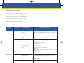
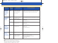
FBR-BK P2728
3/31/06
4:34 PM
Page 12
FiberOptix AP Sensor
Zeroing and Calibration Guide
TM
INTRA-AORTIC BALLOON
PRODUCT SUPPORT HOTLINE
U.S. and Canada:
1-800-447-IABP (4227)
Worldwide:
617-389-8628
Caution: U.S. Federal Law limits this device to sale by or on order of a physician.
Contents of unopened, undamaged package are sterile. Disposable. Refer to
package insert for current warnings, indications, contraindications, precautions,
and instructions for use.
U.S. Patent Nos. 6,258,035, 6,569,103 and 6,887,206
Distribution Worldwide:
Arrow offices are located in Belgium, Canada, Czech Republic, France, Germany, Greece, India, Italy,
Japan, Mexico, Netherlands, Slovakia, South Africa, Spain, and the United States.
Arrow International, Inc., 2400 Bernville Road, Reading, PA 19605 U.S.A. Tel: 610-378-0131
www.arrowintl.com
FBR-BK
3/06
CRB-06-0070
© 2006 Arrow International, Inc. All rights reserved. Printed in the Czech Republic.
E
C A R D I AC AS S I ST
FBR-BK P2728
3/31/06
4:34 PM
Page 2
Arterial Pressure (AP) Fiber Optic Sensor (FOS) Zeroing
Automatic Zero
There are 2 ways to zero the fiber optic sensor on the
FiberOptix intra-aortic balloon (IAB): manually and automatically. For either zero procedure, the blue FOS slide and
black CAL key must be connected to the pump prior to
IAB insertion.
The AP FOS can automatically zero when the following
conditions are present:
1. FOS connector and CAL key are connected
2. Data from CAL key has been downloaded to intra-aortic
balloon pump (IABP)
3. No AP waveform is detected
4. The fiber optic electronics have reached the normal
operating temperature
NOTE: The AP FOS will automatically zero even if FIBER
OPTIC is not first selected.
Connect blue sensor and CAL key PRIOR to insertion.
This is the only time the sensor will be exposed to atmospheric pressure. In an emergent situation, where the zero
procedure cannot be performed due to a deteriorating
patient condition, insert the IAB in the usual fashion and
initiate support. Later, manual calibration can be performed
as described in the AP Fiber Optic Sensor Calibration
section.
Prior to any connections, the following message will be
displayed when the AP SELECT key is pressed and FIBER
OPTIC is illuminated:
Connect fiber optic sensor and CAL key
Zero prior to IAB insertion
Manual Zero
It does not matter which connection is made first, the
CAL key or the blue slide housing the FOS. However, it
is important to ensure the fiber optic connection is made
securely by listening for 2 clicks as the connection is made.
To perform a manual zero with the connections made, verify
FIBER OPTIC is illuminated next to the AP SELECT key and
press the soft key under FOS ZERO. The blue light bulb on
the screen will turn green when the zero is completed.
NOTE: If resistance is met during connection, DO NOT
FORCE the connection. Pull the slide connector back slightly
and re-attempt the connection. Generally, the connection is
made on the first or second attempt.
Once the IAB is inserted into the patient and connected
to the IABP system, the fiber optic cable should be taped
to the driveline tubing in several places.
A message at the bottom of the screen will also be present
to confirm the zero.
If conditions do not allow for zeroing the sensor prior to
insertion, then insert the IAB and proceed to the AP Fiber
Optic Sensor Calibration section if needed.
FBR-BK P2728
3/31/06
4:34 PM
Page 4
NOTE: The WAVE® timing algorithm will perform properly
whether the FOS is zeroed or not. However, the accuracy
of the sensor's numerical values and waveform may be
affected by not zeroing the sensor prior to insertion, similar
to not zeroing a transduced fluid-filled AP source.
A description of the code, possible alarms associated with
that status code, and the issues that may result in the code
being displayed are shown. The Fiber Optic Message Guide
also reviews possible symptoms, related status codes,
causes, and recommended actions.
AP Fiber Optic Sensor Calibration
In all cases, if the fiber optic system is or becomes nonoperational, an alternate AP source will automatically be
In some cases it may not be possible to zero the FOS prior
to insertion. This may result in less accurate hemodynamic
values for the AP signal, similar to when a fluid-filled transducer is not zeroed. Since the FOS cannot be zeroed once
the IAB is inserted into the patient, a method to adjust the
AP values is available. The FOS calibration function allows
the user to adjust the MAP value to another MAP value
which is known to be accurate. To perform this calibration,
press AP SELECT and verify FIBER OPTIC is selected.
Press the FOS MAP CAL function key. This will display the
current MAP value that is being displayed by the FOS. Verify
that the MAP from another AP source is accurate. Use the
< or > keys to adjust the MAP value. This is an active
adjustment; no confirmation key press is required.
selected by AutoPilot ™. If Operator mode is selected,
an alternate AP source needs to be selected by the user.
NOTE: The loss of the fiber optic signal does not impair
functionality of the IABP system.
Fiber Optic Sensor Status Codes
This section details the status messages that are issued
by the fiber optic system. They are designed to verify the
current FOS status and assist in providing specific information for identifying and resolving FOS issues. To view the
code, press the HOME key
NOTE: Once this calibration is completed, it is generally not
required again.
Fiber Optic Sensor Diagnostics
The following sections provide detailed information on
specific issues with the fiber optic system. Status messages or codes may be viewed by the operator during the
course of therapy and provide information relative to the
current operational status of the fiber optic electronics,
connections, and sensor.
then the SHOW STATUS key.
FBR-BK P2728
3/31/06
4:34 PM
Page 6
Fiber Optic Sensor Status Codes
Status Code
Description
Possible Alarm
Possible Issues
OK
FOS electronics and sensor are
working properly and ready for use
None
• None
NO COMM
No communication between CPU
and FOS electronics
System error 8
• FOS PCB failure
• FOS PCB or CPU cable disconnect
• Loss of power to FOS PCB
• CPU failure
LL
Low light return
AP FOS weak
signal
• Sensor not fully connected
• FOS cable is damaged or broken
• Connections are dirty
• Connection is damaged
• FOS board failure
SL
Strong light
AP FOS signal
out of range
• Sensor not properly connected
• Connections are dirty
• Connection is damaged
CK
CAL key missing or data are corrupt
AP FOS CAL key
missing or corrupt
• CAL key not connected
• CAL key data corrupt
• Ribbon cable loose or disconnected
TL
FOS electronics outside of operating
temperature
AP FOS signal
out of range
• FOS warming up at start-up
• FOS heating circuit failure
• Loss of power to FOS electronics
• Air conduit blocked
BL
FOS is measuring barometric pressure
outside of operating range
AP FOS signal
out of range
• Altitude exceeds 8000 ft
• FOS electronics failure
RE
Ratiometric error
PL
FOS is measuring outside of pressure
range
AP FOS signal
out of range
• Excessive pressure on sensor
• Sensor has been damaged
IE
Instrument error
System error 8
or no alarm
• Unknown error
EO
Excessive offset: Zeroing procedure
resulted in a large difference from
factory set calibration
None
• Zero was not completed properly or
occurred when the sensor was disconnected
or partially connected
LT
Loading calibration table
None
• If it goes away within 10 seconds, no problem
• If it stays longer and the zero does not
complete, the key may be damaged or corrupt or
the ribbon cable may be disconnected
SZ
Sensor zeroing
None
• None, unless longer than 1 minute (see “FOS
does not zero” in the Fiber Optic Sensor
Message Guide)
RS
Communication failure
System error 8
• FOS electronics failure
ST
Self-test: Ongoing self-test that does
not complete
System error 8
• FOS electronics failure
• Incorrect calculations
• CAL key may be damaged or corrupt
• Possible FOS PCB failure
FBR-BK P2728
3/31/06
4:34 PM
Page 8
Fiber Optic Sensor Message Guide
This section discusses messages that may occur when
using the fiber optic system. The expected or related FOS
status code is shown, potential causes are detailed, and
recommended solutions given. Some actions may be
done by the user. Those items shown in italics should
be performed by qualified service personnel.
Fiber Optic Sensor Messages
Message
FOS does not zero
FOS does not zero
FOS Status
Code
Potential Causes
Recommended Solutions
LL
Sensor not fully
connected
• Remove blue slide then reconnect
• Verify 2 clicks and audible tone are heard (sensor should zero
within 1 minute)
LL
Sensor cable damaged
or broken
• Use alternate AP source or replace IAB
LL
Sensor interface block
is dirty or damaged
• Clean FOS connector using procedure recommended in
Chapter 10 of the service manual
• Replace FOS track assembly
• Call Field Service
CK
CAL key not connected
or corrupt
• Connect CAL key
• Disconnect then reconnect CAL key
• Replace IAB
• Check cable connected to rear of CAL key front panel connector
• Replace IABP
• Call Field Service
TL
FOS electronics are
outside of operating
temperature range
• It may take up to 5 minutes for the message to clear
• Insert IAB without zeroing (use FOS MAP CAL function if
numerical values are not accurate)
• Call Field Service
LT
Calibration table loading or
loading error
• Wait up to 20 seconds for calibration data to load
• Remove and reconnect CAL key
• Replace IAB
• Exchange IABP console
• Call Field Service if problem occurs
FBR-BK P2728
3/31/06
Message
4:34 PM
FOS Status
Code
Page 10
Potential Causes
Recommended Solutions
FOS light bulb
turns green in
<10 seconds or
on connection
of a new
IAB sensor
EO
Current sensor has been
connected and zeroed
prior or sensor did not
zero correctly
• If IAB is not inserted, insert another CAL key; when light bulb
changes to blue, disconnect CAL key and re-insert the CAL key
that is attached to the IAB. Sensor should zero properly
No FOS waveform
is displayed or
waveform is
off screen
EO
Zeroing process was not
completed correctly
• Use FOS MAP CAL function if numerical values are not accurate
LL
Broken or damaged cable
• Replace IAB
• Use alternate AP source
PL
Sensor damaged or
improperly zeroed
• Use FOS MAP CAL function if numerical values are not accurate
• Replace IAB
• Use alternate AP source
No FOS waveform
is seen and
numerical values
are >350 mm Hg
or <0 mm Hg
PL
Sensor damaged or
improperly zeroed
• Use FOS MAP CAL function if numerical values are not accurate
• Replace IAB
• Use alternate AP source
FOS signal lost
(signal was
present but is no
longer displayed)
LL
FOS cable damaged or
broken
• Replace IAB
• Use alternate AP source
LL
FOS not connected or
partially connected
• Remove blue slide then reconnect
• Verify 2 clicks and audible tone are heard
• Use alternate AP source
• Replace IAB
NOTE: If the IAB is in the patient with first zeroing, the
light bulb will remain blue but the waveform should appear
if the sensor is functional. If needed, follow the steps in
the AP Fiber Optic Sensor Calibration section to adjust
the fiber optic sensor MAP values.