1
CODE : 00Z ARSP10/S1E
Digital copier
Reverse Single
Pass Feeder (RSPF)
Single Pass Feeder (SPF)
AR-RP10
MODEL AR-SP10
CONTENTS
[1]
PRODUCT OUTLINE . . . . . . . . . . . . . . . . . . . . . . . . . . . . . . . . . . 1
[2]
SPECIFICATIONS . . . . . . . . . . . . . . . . . . . . . . . . . . . . . . . . . . . . 1
[3]
EXTERNAL VIEW AND INTERNAL STRUCTURE . . . . . . . . . . . 2
[4]
OPEREATIONAL DESCRIPTIONS . . . . . . . . . . . . . . . . . . . . . . . 3
[5]
ADJUSTMENTS . . . . . . . . . . . . . . . . . . . . . . . . . . . . . . . . . . . . . . 5
[6]
DISASSEMBLY AND ASSEMBLY . . . . . . . . . . . . . . . . . . . . . . . . 7
[7]
MAINTENANCE . . . . . . . . . . . . . . . . . . . . . . . . . . . . . . . . . . . . . 14
[8]
ELECTRICAL SECTION . . . . . . . . . . . . . . . . . . . . . . . . . . . . . . . 15
Parts marked with "!" are important for maintaining the safety of the set. Be sure to replace these parts with specified
ones for maintaining the safety and performance of the set.
SHARP CORPORATION
This document has been published to be used
for after sales service only.
The contents are subject to change without notice.
[1] PRODUCT OUTLINE
2. Document exchange speed
AR-RP10
This machine is a duplex document auto feeder attached to a digital
copier.
Transport
speed
Transport
speed
Document
conversion rate
S-S 2020 sheets/
sheet
min
machine
100%
20 sheets/
min
100%
1616 sheets/
sheet
min
machine
100%
16 sheets/
min
100%
It feeds originals automatically to allow continuous copying.
[2] SPECIFICATIONS
1.Basic specifications
AR-RP10
AR-SP10
Document set direction
Face up
Document set position
Right/Center reference
Document transport
system
Sheet through type
Document feed sequence Top take-up feed
Document size
AB series: A3 ~ A5
Inch series: 11 x 17 ~ 8.5 x 5.5
Document weight
56 ~ 90g/m2, 15 ~ 24lbs
Document set quantity
The thickness of the document bundle
must be 4mm or less or 40 sheets or less.
40 sheets (when 80g/m2 or less)
30 sheets (B4 or 8.5 x 13 or above)
Dimensions
586mm (W) x 440mm (D) x 132mm (H)
Weight
About 5.4 kg
S-D 209 sheets/min
sheet
or above
machine
45%
169 sheets/min
sheet
or above
machine
56%
D-D 208 sheets/min
sheet
or above
machine
40%
168 sheets/min
sheet
or above
machine
50%
About 5.3 kg
Power source
Supplied from the copier. (DC 24V, 5V)
Power consumption
26.4W
21W
Document size detection On the document feed tray
Detection size
Japan:
Inch series:
Mixture of different
document sizes
Mixture paper feed: Not available
Random paper feed: Not available
Document reverse
Allowed
(without 8.5 x 5.5)
Display section (LED)
None
A3, B4, A4, A4R, B5, B5R
11 x 17, 8.5 x 14, 8.5 x 11,
8.5 x 11R, 8.5 x 5.5, 8.5 x 13
EX AB series: A3, B4, A4, A4R, A5, 8.5 x 13
Not allowed
AR-SP10/RP10
PRODUCT OUTLINE
–1–
AR-SP10
Document
conversion rate
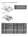
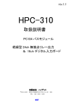
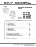
[3] EXTERNAL VIEW AND INTERNAL STRUCTURE
1. External view
No.
Name
1
Document set tray
2
Document guide
3
Document feed section cover
4
Document transport section cover
5
Document exit section
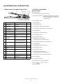
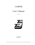
2. Internal structure
13
12
11
10
8
9
6
7
15
14
5
2
4
3
1
Sensor, detector, etc.
No.
Code
1
W0
2
3
4
5
Name
Type
Function/Operation
Document set sensor
Photo transmission Detects presence of documents.
COVER
Open/close sensor
Photo transmission Detects open/close of the paper feed unit.
W1
Document width sensor (A4R, LTR, A5)
Photo transmission Detects the document width on the tray.
W2
Document width sensor (B4, B5)
Photo transmission Detects the document width on the tray.
W3
Document width sensor (WL, TR, A5R, A4, LT) Photo transmission Detects the document width on the tray.
6
PSOL
Pickup solenoid
7
PAPER
Paper entry sensor
—
—
Photo transmission Detects presence of documents.
8
RSOL
Pressure release solenoid
—
—
9
CLH
Transport clutch
—
—
10
MOT
SPF (RSPF) motor
11
12
—
Note
Stepping motor
Interface PWB
Drives document feed on the tray, transport, and paper exit roller.
—
—
L1
Document length detection SW (Short)
Photo transmission Detects the document length on the tray.
13
L2
Document length detection SW (Long)
Photo transmission Detects the document length on the tray.
14
COVER OPEN Book sensor
Photo transmission Detects the SPF (RSPF) float.
15
PO
Photo transmission Detects presence of documents.
Paper exit sensor
AR-SP10/RP10
EXTERNAL VIEW AND INTERNAL STRUCTURE
–2–
AR-RP10 only
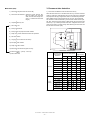
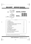
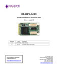
[4] OPEREATIONAL DESCRIPTIONS
1. Major parts of the paper feed section
1
2
3,4 5 6
2. Out line of operations
■ AR-RP10 (RSPF)
7 8
[Duplex documents]
1) Document set (Document set sensor ON)
2) Document size detection (Document width sensors W1, W2, W3
detect the document width, and document length sensors L1, L2 detect the
document length.)
16 14 13 12 15 11 10 9
3) Copier START key ON
No. Part name
Operation
4) RSPF motor ON
Note
1
Document length
sensor (L2)
Detects the document length
on the tray.
5) Pickup solenoid ON
2
Document length
sensor (L1)
Detects the document length
on the tray.
6) Pickup roller and paper feed roller rotation
3
Document set
sensor (W0)
Detects presence of documents.
7) Paper entry sensor detects the document presence.
4
Picks up documents.
Paper feed roller
Feeds and transports documents.
9
8) PS roller rotation
10) Transport roller rotation
11) Paper exit roller rotation
Paper entry sensor
(PAPER)
Detects transport of documents.
PS roller
Makes synchronization
between the document lead
edge and the image lead edge.
PS follower roller
9) Copying (Front surface of document)
Pickup roller
6
8
Document width
Detects the document width.
sensor (W1, W2, W3)
5
7
12) Paper exit roller reverse rotation
(Documents are fed to the reverse path.)
13) Paper entry sensor detects document presence.
Makes synchronization
between the document lead
edge and the image lead edge.
14) PS roller rotation
15) Copying (Back surface of document)
10
Transport roller
Transports documents.
11
Transport follower
roller
Transports documents.
12
Paper exit sensor
(PO)
Detects transport of documents.
17) Paper exit roller rotation
13
Paper exit follower
roller
Discharges documents.
18) Paper exit roller reverse rotation
(Documents are fed to the reverse path.)
14
Paper exit roller
Discharges documents.
15
Reverse gate
Opens/closes the document
reverse path.
16
Paper holder
16) Transport roller rotation
19) Paper entry sensor detects document presence.
20) PS roller rotation
Holds the discharged paper.
21) Paper exit roller rotation
22) Documents are fed to the paper exit tray.
23) Next document (YES) Go to 5).
(NO)
24) RSPF motor OFF
AR-SP10/RP10
OPEREATIONAL DESCRIPTIONS
–3–
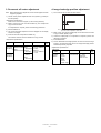
3. Document size detection
■ AR-SP10 (SPF)
1) Document set (Document set sensor ON)
1) Document size detection with the document set tray
When documents are set on the document set tray in the auto selection
mode of paper/copy magnification ratio, the document size is detected
and paper and the copy magnification ratio are automatically selected.
When different sizes of documents are set, the max. size is detected.
The document width is detected by the document width sensors (W1,
W2, W3), and the document length is detected by the document length
sensors (L1, L2) to identify the document size. Judgement of the document size is made in a certain timing after detecting the document with
the document set sensor (W0).
2) Document size detection (Document width sensors W1,
W2, W3 detect the document
width, and document length sensors L1, L2 detect the document
length.)
3) Copier START key ON
4) SPF motor ON
5) Pickup solenoid ON
6) Pickup roller and paper feed roller rotation
7) Paper entry sensor detects the document presence.
8) PS roller rotation
9) Copying (Front surface of document)
10) Transport roller rotation
11) Paper exit roller rotation
12) Documents are fed to the paper exit tray.
13) Next document (YES) Go to 5).
(NO)
14) SPF motor OFF
Document set
size and set
direction
AB series
Inch
series
Document width sensor
W1
W2
W3
L1
L2
A5
{
z
z
z
z
B5
{
{
z
z
z
A5R
z
z
z
z
z
A4
{
{
{
z
z
B5R
z
z
z
{
z
A4R
{
z
z
{
z
8.5” x 13”
{
z
z
{
{
B4
{
{
z
{
{
A3
{
{
{
{
{
8.5” x 5.5”
{
z
z
z
z
8.5” x 5.5”R
z
z
z
z
z
11” x 8.5”
{
{
{
z
z
11” x 8.5”R
{
z
z
{
z
8.5” x 13”
{
z
z
{
{
8.5” x 14”
{
z
z
{
{
11” x 17”
{
{
{
{
{
Note: Detection sensor ON: {, OFF: z
AR-SP10/RP10
OPEREATIONAL DESCRIPTIONS
–4–
Document
length sensor
[5] ADJUSTMENTS
2. Magnification ratio adjustment
Note: • When performing this adjustment, check that the CCD unit is
properly installed.
1. Auto white correction pixel adjustment
• When performing this adjustment, check that the OC mode
adjustment in copying is completed.
1) Open the SPF (RSPF) unit.
1) Place a scale on the document table as shown below, and make a
normal copy to make a test chart.
2) Execute Sim63-7.
3) The 7-seg display indicates the order number of the pixel of the
white sheet for SPF (RSPF) exposure correction in the SPF (RSPF)
position.
• It will display on 7-seg display, if values are 93-229, and data are written into the EEPROM.
(In this case, it means that the adjustment has been normally completed.)
• It will display on 7-seg display, it values are 0-92 or 230-999, and data
are not written into the EEPROM.
Note: Since the printed paper is used as the test chart,
place the scale in parallel to both sides.
2) Set the test chart to the SPF (RSPF) and make a normal copy.
• It will display "--" on 7-seg display, it values is 1000 or larger, and data
are not written into the EEPROM.
(In these cases, the adjustment has not been normally completed.
Troubleshoot the cause and perform the adjustment again. )
3) Compare the copy and the test chart.
If an adjustment is needed, perform the following procedures.
4) Execute SIM 48-5.
5) The current correction value is displayed on the display section in
two digits.
Note: If the operation is executed with the SPF unit closed, an error
occurs.
Also when the lens unit is replaced or when the optical axis of the
lens unit is shifted, an error occurs.
In this case, it is necessary to perform the adjustment of the lens
unit described in “SPF white correction pixel position adjustment”
of the Service Manual of the machine.
6) Enter the set value, and press the START key.
The entered correction value is stored and a copy is made.
7) Change the TEXT mode.
The TEXT indicator lights up, and the current correction value of the
back surface sub scanning direction magnification ratio is displayed
on the display section in two digits.
8) Enter the set value, and press the START key.
The entered correction value is stored and a copy is made.
<Adjustment specifications>
Mode
Magnification
ratio adjustment
AR-SP10/RP10
ADJUSTMENTS
–5–
Spec
SIM
Set value
Set
range
Normal:
SIM 48-5
Add 1:
1 ~ 99
± 1.0% AUTO:
0.1% increase
Reduce 1:
Surface
0.1% decrease
TEXT: Back
3. Document off center adjustment
4. Image lead edge position adjustment
Note: When performing this adjustment, check that the paper off-center
is properly adjusted.
1) Set a scale on the OC table as shown below.
1) Set the center position adjustment test chart (made by yourself) on
the SPF (RSPF).
<Adjustment specifications>
Draw a line in the center of paper. (In the scanning direction)
2) Make a normal copy from the manual feed tray, and compare the
copy and the test chart.
If an adjustment is required, perform the following procedures.
3) Execute SIM 50-12.
Note: Since the printed paper is used as the test chart,
place the scale in parallel to both sides.
4) The current off-center adjustment value is displayed on the display
section in two digits.
2) Make a copy, and use the copied paper as the document and make
a copy from SPF (RSPF) again.
5) Enter the set value and press the START key.
The entered correction value is started and a copy is made.
3) Check the copied paper. If an adjustment is required, perform the
following procedures.
<Adjustment specifications>
Mode
Specification
4) Execute SIM 50-6.
SIM
Set value
5) Set the SPF/RSPF lead edge position set value so that the image
similar to the adjusted image at the OC image lead edge position
described previously is printed.
Set
range
Document Simplex:
SIM 50-12
Add 1:
1 ~ 99
off-center Center ± 3.0mm TEXT:
0.1mm shifted to
(AR-RP10) Duplex:
SPF surface R side.
Center ± 3.5mm PHOTO:
Reduce 1:
SPF back
0.1mm shifted to
L side.
Document
AUTO:
Surface
off-center
(AR-SP10)
TEXT:
SPF surface
<Adjustment specifications>
Adjustment
mode
Image
lead edge
position
AR-SP10/RP10
ADJUSTMENTS
–6–
SIM
Set value
SIM 50-6
1step:
AUTO:
0.1mm shift
Front
TEXT:
Back
PHOTO:
Rear edge
Specification
Lead edge void:
1 ~ 4mm
Image loss:
3mm or less
Set
range
1 ~ 99
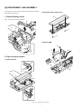
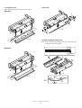
[6] DISASSEMBLY AND ASSEMBLY
2) Document feed section cover
The connector is of the lock type. When disconnecting the connector,
press the lock and pull it out.
2
1. External fitting section
Note: Turn the paw in the arrow direction.
2
3
1
1
1
3) Sensor PWB
2
1
3
4
2. Paper feed unit section
1) Paper feed unit
1
2
2
2
1
1
AR-SP10/RP10
DISASSEMBLY AND ASSEMBLY
–7–
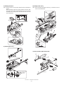
4) Pickup solenoid
6) Pickup roller ass’y
Note: Remove section A of the pickup solenoid from the solenoid arm
groove.
When assembling, adjust the spacing between the clutch latch
and sleeve with the pick-up solenoid pulled. The size should be
the distance from the tip of the clutch latch and the root of the
clutch sleeve latch.
Note: When assembling the pickup roller ass’y 4, check that rib A is on
the rib of the solenoid arm.
A
1
2
1
A
2
2.5
4
4.5mm
3
5) Clutch gear ass’y
6
7) Pick up roller, paper feed roller
4
6
5
3
1
1
1
2
3
4
2
From Edge pawl
1
2.5~4.5
AR-SP10/RP10
DISASSEMBLY AND ASSEMBLY
–8–
3. Interface PWB
2) Rack cover
1
1
1
2
1
2
1
B
A
3) Document length sensor SW
B
1
A
1
2
1
4. Document tray section
1) Document tray
3
2
1
1
AR-SP10/RP10
DISASSEMBLY AND ASSEMBLY
–9–
2
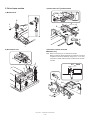
5. Drive frame section
3) Drive frame ass’y and drive belt
1) Book sensor
2
1
1
2
3
3
4
2) Drive frame unit
4) Pressure release solenoid
■ AR-RP10 only
Note: Make sure the spring pin A is inserted into the slot.
Make sure that the clearance between the position at which force
is applied and the sound deadening sponge is 0.5 ~ 2 mm when
the pressure release solenoid plunger is pulled toward the solenoid side.
1
1
0.5
1
2mm
2
1
A
3
1
2
AR-SP10/RP10
DISASSEMBLY AND ASSEMBLY
– 10 –
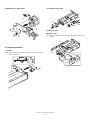
5) RSPF motor / SPF motor
2) Transport roller gear
1
1
1
1
1
1
4
3) Reverse gate
3
■ AR-RP10 only
Note: When assembling the inversion gate, apply grease G-484 on the
area A.
2
3
6. Transport section
A
A
1) Clutch
Note: When assembling, check that the rib is in the clutch groove A
and fix it with E-ring.
A
2
2
A
AR-SP10/RP10
DISASSEMBLY AND ASSEMBLY
– 11 –
1
4) Transport roller
5) PS roller
Note: Note that the spring will come off when removing.
■ AR-SP10
1
1
1
1
2
1
1
6) Paper feed paper guide lower
Note: When assembling, check that the paper feed paper guide lower
is securely set to rib A and boss B.
+
-1mm
■ AR-RP10
0 0.5mm
2
1
1
1
1
B
AR-SP10/RP10
DISASSEMBLY AND ASSEMBLY
– 12 –
A
7. Hinge L
7) Paper feed paper guide upper
Note: When assembling the hinge L, reference is based on the mark of
base tray and the center line of the 5 lines of the hinge L
extended horizontally.
2
1
2
1
1
8) Paper exit roller
1
1
2
AR-SP10/RP10
DISASSEMBLY AND ASSEMBLY
– 13 –
1
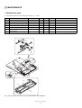
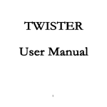
[7] MAINTENANCE
1. Maintenance parts
x : Check (Clean, adjust, or replace according to necessity.)
No.
When calling
50K
100K
150K
Pickup roller
{
{
{
{
*1
2-1
Separation unit
x
x
x
x
Replace when worn down.
2-2
Front separation sheet
x
x
x
x
1
Name
{ : Clean
3
Paper feed roller
{
{
{
{
4
PS roller
{
{
{
{
5
Transport roller
x
x
x
x
6
Paper exit roller
x
x
x
x
Remark
*1
*1 Replacement reference: Replace when the SPF counter (SIM22-8) reaches 100K or the usage time reaches 1 year.
1
3
2-2
2-1
6
5
4
Note: When performing maintenance, refer to [7] DISASSEMBLY AND ASSEMBLY.
AR-SP10/RP10
MAINTENANCE
– 14 –
AR-SP10/RP10
ELECTRICAL SECTION
– 15 –
A
B
C
D
7
YSPF
7
PDOWNA
PDOWNB
SPF(MODA,MODB,
/MODA,/MODB)
5
MOTOR
DRIVER
24V
2
24V
/RSOL
24V
24V
/PSOL
MOTOR
(A,B,/A,/B)
24V
/CLH
5V
/SPFOUT
/SPFCOVER
/SPFOUT
3
24V
L1
SPF SENSOR PWB
W0
W1
W2
W3
24V
L2
2
5V
4
3
SPFOPEN
6
4
SPFOPEN
TRANSISTOR
ARRAY
5V
DATA
SELECTOR
SPF/RSPF INTERFACE PWB
5
5V
PAPER
SPF(CLH,PSOL,RSOL,GSOL)
8
6
PAPER
/SPFCOVER
SEL(A#,B#,C#)
PEGASUS
(MCU PWB)
1. Block diagram
[8] ELECTRICAL SECTION
8
1
RSPF ONLY
SOL/CLU
5V
SENSOR
1
A
B
C
D
AR-SP10/RP10
ELECTRICAL SECTION
– 16 –
A
B
C
D
7
(Paper Exit Sensor)
/SPFOUT
(Book Sensor)
8
SPFOPEN
5V
/SPFOUT
SPFGSOL
8
9
10
11
12
13
14
15
-
12
13
15
18
24
19
22
N.C.
SGND
SGND
YSPF
SPFOPEN
5V
/SPFOUT
SPFGSOL
BL
SELC#
7
6
SELC#
5
24V1
PDOWNA
SPFPSOL
20
21
8
10
PDOWNA
SPFPSOL
SPFCLH
3
2
1
3
2
1
DF3-3S-2C
7
OR
GR
OR
GR
OR
BR
GY
GY
PHR-3(BK)
PHR-3(RD)
BL
GY
DF3-3S-2C
OR
BR
GY
BL
BL
PHR-3
FG
/CLH
N.C.
24V1
5V
SPF0PEN
SGND
3
2
1
5V
6
/SPFOUT
SGND
CN2
B3B-PH-K-K(BK)
3
2
1
CN1
B3B-PH-K-R(RD)
3
2
1
CN7
B3B-PH-K-S
24V
26
2
24V
SRA-21T-4
24V
25
1
24V
12
10
19
8
18
17
13
4
16
15
2
11
6
14
24V1
24V1
N.C.
7
6
5
4
3
/B
B
2
1
/A
A
CN3
B7B-PH-K-S
24V1
/RSOL
PAPER
PGND
24
14
PGND
26
pull up
PGND
23
11
PGND
FG
SGND
PDOWNB
22
23
PDOWNB
SGND
L2
SPFCLH
19
SPFCLH
SGND
5V
/SPFMODA
18
4
21
/SPFMODA
L1
SPFRSOL
17
9
5V
/PSOL
SGND
YSPF
SPFMODA
3
9
7
1
5
SPFCOVER 20
W3
W2
W1
5V
W0
CN6
B20B-PUDSS
SGND
SGND
Interface PWB
5
SPFRSOL
EARTH PLATE(SPF ONLY)
SPFOPEN
SRA-21T-4
/SPFMODB
6
3
/SPFMODB
SRA-21T-4
SELB#
5
7
SELB#
16
SPFMODB
4
17
SPFMODB
5
SELA#
3
20
SELA#
SPFMODA
/SPFCOVER
2
16
/SPFCOVER
N.C.
PAPER
1
25
CN5
B26B-PUDSS
6
PAPER
MCU PWB
2. Actual wiring diagram
8
PHDR-20
4
RD
GY
OR
BL
GY
GY
OR
BL
GY
7
6
5
4
3
2
1
2
1
SGND
L2
5V
SGND
L1
5V
2
3
SMR-02V-N(JST)
PHR-6
BL
RD
RD
PL
RD
RD
PL
PK
24V1
PK
2
LB
RD
LB
BL
RD
LB
BR
BR
GY
BL
OR
GY
LB
OR
GY
PK
LB
BR
PL
OR
BL
PL
DF3-3S-2C
DF3-3S-2C
PHR-7
PHR-3 GY
PHNR-6-H
GY
BL
OR
GY
LB
OR
PHNR-2-H
PHNR-7-H
GY
PK
LB
BR
PL
OR
BL
PL
1
6
5
4
3
2
1
BU6P-PA-P-H
24V1
SPFPSOL
BU2P-PA-P-H
SGND
SPFCOVER
W3
W2
W1
5V
W0
BU7P-PA-P-H
SMP-02V-BC(JST)
LB 1 SPFRSOL
1
2
3
4
5
6
1
2
1
2
3
4
5
6
7
3
GY
PHR-7
LB
LB
PHNR-6-H
OR
OR
PHNR-2-H
BL
RD
PHNR-7-H
GY
PK
LB
BR
PL
OR
BL
BL
GY
PK
LB
BR
PL
OR
BL
4
SGND
SPFCOVER
W3
W2
W1
5v
W0
2
5
2
4
6
1
3
24V1
24V1
B
/B
/A
A
SPFRSOL
3
1
2
1
2
3
1
2
3
SPFPSOL
7
6
5
4
3
2
1
2
ORIGINAL TRAY
PLUSE MOTOR
1
DSPF ONLY
PAPER
(Paper Entry Sensor)
L2
L1
PAPER FEED UNIT
Sensor PWB
1
A
B
C
D
– 17 –
A
B
C
D
7
(C4) CN1-22
(C4) CN1-20
(A3) CN2-7
(A3) CN2-9
(A3) CN2-3
(A3) CN2-5
(A3) CN2-15
(A3) CN2-13
C126
10k
Q101
DTC114EK
10k
TP101
$PIN0
SELC SELB SELA
L
L
L
L
L
H
L
H
L
L
H
H
H
L
L
L
H
H
H
L
H
H
H
H
PDOWNB
8
C125
Senser Mtorix
PDOWNA
W1
W2
W3
W0
L1
L2
Document size senser
R116
10K
C124
R114
10K
10k
7
R103
620F
R110
110F
5V
5V
R111
10K
C109
0.1u/25V
R113
10K
JP1
DSPF
C122
R112
10K
R109
430F
C121
R115
10K
Q102
DTC114EK
10k
TP102
$PIN0
R108
390F
TP103
Y
W1
W2
W3
W0
L1
L2
SPF(H)/DSPF(L)
/SPFDTC (L)
1000pF/50V*7
C123
R117
10K
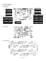
3-1. Interface PWB (1/2)
3. Circuit Diagram
8
$PIN0
ELECTRICAL SECTION
1
AR-SP10/RP10
C2
10u/16V
/SPFDTC
6
R106 2.4k
GND
Y
VCC
W
C113
2200pF/
50V
5
ZD101
UDZ5.6
R105
1KJ
R104
1KJ
R107
7.5KJ
/SPFMODA
SPFMODA
/SPFMODB
SPFMODB
C111
3300pF/50V
C112
0.1uF/25V
R2 1.5(1W)
ZD104
UDZ5.6
C120
0.1u/25V
5
C110
3300pF/50V
5V
C108
0.1uF/25V
R101
7.5KJ
R1 1.5(1W)
(C4) CN1-18
(C4) CN1-16
(C4) CN1-6
(C4) CN1-4
74HC151
A
B
C
G
D0
D1
D2
D3
D4
D5
D6
D7
IC101
C107
2200pF/50V
R102 2.4k
6
ZD103
UDZ5.6
ZD102
UDZ5.6
C119
1000p/50V
C117
1000p/50V
4
MTD1361
In /A
In A
In /B
In B
CrA
CrB
VsA
RsA
VrefA
VrefB
RsB
VsB
IC1
4
SELC#
SELB#
SELA#
PG
PG
PG
LG
NC
NC
NC
NC
NC
NC
OUT A
OUT B
OUT /A
OUT /B
Vmm
C104
0.047u/50V
3
C114
0.047u/50V
C1
47u/35V
A
B
/A
/B
2
1C
2C
3C
4C
5C
6C
7C
COM
CN7-6,7 (B3)
CN7-1 (B3)
CN7-4 (B2)
CN7-2 (B3)
CN7-3 (A2)
TD62003AP
1B
2B
3B
4B
5B
6B
7B
GND
C115
0.047u/50V
IC2
2
Pattern width: 0.5mm or above
SPFPSOL
SPFCLH
SPFRSOL
SPFGSOL
Pattern width: 1.0mm or above
C103
0.047u/50V
24V1
CN1-7 (A4)
CN1-5 (A4)
CN1-3 (A4)
CN1-11 (A4)
C118
1000p/50V
YSPF
(A4) CN1-21
(A4) CN1-19
(A4) CN1-17
(A4) CN1-15
3
24V1
/PSOL
/CLH
/RSOL
/GSOL
1
1
CN2-6 (B3)
CN6-3 (B2)
CN2-10 (B3)
CN3-3 (A2)
A
B
C
D
AR-SP10/RP10
ELECTRICAL SECTION
– 18 –
A
B
C
D
8
(E3)
5V
(D4)
(D4)
(D4)
(D4)
CN2-19 (A3)
(E3)
(E3)
(E3)
YSPF
5V
SPFGSOL
SFPRSOL
SPFCLH
SPFPSOL
PAPER
SELA#
SELB#
SELC#
(E4)
(E4)
(E4)
(E4)
3-2. Interface PWB (2/2)
8
7
B
/B
A/
A
(E4)
24V1
2
4
6
8
10
12
14
16
18
20
22
24
26
7
6
5
4
3
2
1
CN3
B2B-PH-K-S
B3B-PH-K-R(RD)
1
2
3
1
2
C105
0.047u
F1
ICP-N38
SPFOPEN
/SPFOUT
SPFMODA
/SPFMODA
PDOWNA
PDOWNB
/SPFCOVER
SPFMODB
/SPFMODB
CN1
6
C106
0.047u
6
CN4
B26B-PUDSS
1
3
5
7
9
11
13
15
17
19
21
23
25
CN5
B7B-PH-K-S
24V1
/GSOL
C116
0.1u/25V
C3
10u/16V
+
7
5V
5
C101
0.1u/25V
SPFOPEN
24V1
CN4-2 (B2)
(B2) CN5-2
(C1)
(C1)
(B1)
(B1)
CN2-20 (B3)
(C1)
(C1)
5
CN1-12 (C4)
4
4
B3B-PH-K-E(BL)
1
2
3
CN2
CN1-1 (A4)
(B3)
(B3)
(B3)
(B3)
(B3)
(B3)
5V
2
4
6
8
10
12
14
16
18
20
B20B-PUDSS
1
3
5
7
9
11
13
15
17
19
CN6
CN1-14 (C4)
5V
3
C102
0.1u/25V
/SPFOUT
C127
0.1u/25V
PAPER
L2
L1
W3
W0
W1
W2
24V1
3
2
(E4)
R118
470
2
5V
/CLH
24V1
1
2
3
CN7
CN1-2 (C4)
(E4)
(D4)
B3B-PH-K-S
/SPFCOVER
/RSOL
/PSOL
R119
470
1
1
A
B
C
D
AR-SP10/RP10
ELECTRICAL SECTION
– 19 –
5
4
4
3
3
2
2
1
1
B
A
B
A
C
6
5
C
7
6
D
8
7
D
3-3. Sensor PWB
8
4. Parts arrangement
4-1. Interface PWB
a. Parts surface
CN1(B3B-PH-K-R RD)
CN3(B7B-PH-K-S)
1
A
2
/A
3
/B
4
B
5
N.C.
6
24V1
7
24V1
1
2
3
CN2(B3B-PH-K-E BK)
1
SGND
2
/SPFOUT
3
5V
CN5(B26B-PUDSS)
24V1
24V1
25
26
PGND
PGND
23
24
21 SPFPSOL 22 PDOWNB
19 SPFCLH 20 PDOWNA
17 SPFRSOL 18 /SPFMODA
15 SPFGSOL 16 SPFMODA
5V
13
14 /SPFOUT
YSPF
11
12 SPFOPEN
SGND
SGND
9
10
SELC#
N.C.
7
8
SELB#
5
6 /SPFMODB
SELA#
3
4 SPFMODB
PA PER
1
2 /SPFCOVER
CN4(B2B-PH-K-S)
1
24V1
2
/GSOL
CN6(B20B-PUDSS)
2
5V
1
4
5V
3
6
/PSOL
5
8
Pull up
7
10
/RSOL
9
12
24V1
11
14
SGND
13
16
SGND
15
18
SGND
17
20 SPFCOVER 19
5V
W3
W0
W1
W2
24V1
L2
L1
SGND
PA PER
SGND
SPFOPEN
5V
CN7(B3B-PH-K-S)
1
24V1
2
N.C.
3
/CLH
b. Solder surface
4-2. Sensor PWB
AR-SP10/RP10
ELECTRICAL SECTION
– 20 –
COPYRIGHT 2008 BY SHARP CORPORATION
All rights reserved.
Printed in Japan.
No part of this publication may be reproduced,
stored in a retrieval system, or transmitted.
In any form or by any means,
electronic, mechanical, photocopying, recording, or otherwise,
without prior written permission of the publisher.
SHARP CORPORATION
Digital Document Systems Group
CS Promotion Center
Yamatokoriyama, Nara 639-1186, Japan
2008 September Printed in Japan
N