1
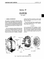
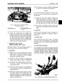
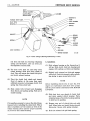
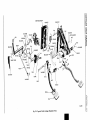
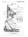
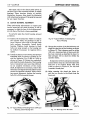
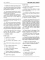
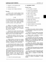
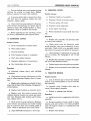
Section IV
CLUTCH
SERVICE BULLETIN REFERENCE
NUMBER
DATE
SUBJECT
CHANGES
106—CLUTCH
CHRYSLER SHOP MANUAL
Section IV
CLUTCH
DATA AND SPECIFICATIONS
C-67
Clutch Model
Type
Facings
Inside Diameter
Outside Diameter
1376
Single Plate
2
6"
10"
9 Brown
218 at 1 2 % 2 " Length
1962 Lbs.
.001"
.002"
Individual Spring Pressure—Lbs
Total Spring Load
Crankshaft Flange Face Runout
Diameter Runout
ESSENTIAL TOOLS
C-360
C-585
C-647
C-41
DD-286
C-870
C-435 or C-430
C-730
C-860
Aligning Arbor (Clutch Disc)
Compressing Fixture (with No. 44 Spacer)
Spring Tester
Remover Tool—Pilot Bushing
.Installing Tool—Pilot Bushing
Fixture—Clutch Housing Aligning
Indicator
Transmission Pilot Studs
Reamer
TIGHTENING REFERENCE
Part Name
Rear Engine Support Insulator Bolts
Clutch Housing Cap Screws
,
Clutch Cover Bolts
Transmission to Clutch Housing Cap Screws
Torque
(Foot-Pounds)
85
35
20
50
CLUTCH—107
CHRYSLER SHOP MANUAL
Section IV
CLUTCH
(C-67 ONLY)
1. GENERAL INFORMATION
The clutch is of the single dry disc type, with no
adjustment for wear being provided in the clutch
itself. An individual adjustment is provided for
locating each lever in the manufacturing process
and should never be disturbed, unless the clutch
is to be removed from the car for repair or overhauling.
The only adjustment required while the clutch
is in the car, is linkage adjustment to obtain the
correct amount of clutch pedal free play. Clutch
pedal free play is the movement of the pedal
before the clutch starts to engage or disengage.
Linkage adjustment is required to restore pedal
free play when it has been reduced by normal
wear of the clutch.
The only service maintenance required is regular periodic lubrication of the clutch (linkage)
torque shaft pivot bearings.
CAUTION
It is very important, when rebuilding or installing a clutch, that the correct clutch disc, pressure
plate and springs be installed. Serious vibration,
noise or grabbing, chattery clutch will result.
(Note the total spring pressure and color of
springs.)
COVER
RELEASE LEVER
RELEASE LEVER
SPRING
ACK
(6-SPRINGS)
STRUT
DISC ASSEMBLY
EYEBOLT
EYEBOLT NUTS
52x524
Fig. 1—Typical Clutch Assembly (Disassembled View)
108—CLUTCH
CHRYSLER SHOP MANUAL
SERVICE PROCEDURES
2. REMOVAL AND INSTALLATION OF CLUTCH
a. Removal
Improper operation or excessive wear may impair the clutch function to the point which may
necessitate its removal and overhaul.
The clutch can be removed only after the
transmission has been removed. To remove the
clutch, proceed as follows:
(1) Remove the transmission.
(2) Remove the clutch housing pan.
(3) Pull out the clutch release bearing and
sleeve.
(4) Mark the clutch cover and flywheel, as
shown in Figure 2. Remove the bolts that
hold the clutch cover to theflywheel.Loosen
each bolt a few turns (in succession) until
cover is free. The clutch disc and pressure
plate assembly can now be removed from
the clutch housing.
b. Installation
When installing the clutch, observe the following
precautions:
Fig. 2—Punch Marks on Clutch Cover and Flywheel
1— Clutch cover
2—Punch marks
3—Engine flywheel
4—Balance drilling in engine
flywheel
Fig. 3—Clutch Disc Aligning Arbor
(Tool C-360)
(1) Coat the transmission drive pinion pilot
bushing (in end of crankshaft) with medium short fiber wheel bearing grease
(about a half teaspoonf ul). Place grease in
O.D. of cavity at inner end of bushing.
(2) Clean the surface of the flywheel and pressure plate thoroughly, making certain that
all oil or grease has been removed.
(3) Hold the clutch disc, pressure plate and
cover in mounting position, with the springs
on the disc facing away from the flywheel.
Insert a spare transmission drive pinion
clutch shaft through hub of disc and into
the pilot bushing. If this item is not available, Tool C-360 may be used, as illustrated
in Figure 3.
(4) Insert the clutch cover attaching bolts
(after aligning balance punch marks) but
do not tighten.
(5) To avoid distortion of the clutch cover, the
bolts should be tightened a few turns at a
time (alternately) until they are all tight.
Tighten the bolts from 15 to 20 foot-pounds
torque. Remove Tool C-360 or pinion shaft
(if used).
CHRYSLER SHOP MANUAL
CLUTCH—109
(6) The cover can now be lifted off exposing
all parts for cleaning and inspection.
NOTE
It is important that a notation is made of the
location of parts, including the arrangement of
the springs.
(7) Grasp the lever and eyebolt between the
thumb and fingers, as shown in Figure 5,
so that inner end of lever and the upper end
of eyebolt are close together (keep the eyebolt pin seated in its socket in the lever).
Fig. 4—Clutch Cover and Pressure Plate
Assembly in Fixture
1 —Clutch cover
2—Clutch pressure plate
3-Fixture (Tool C-585)
4—Punch marks on pressure plate
and cover
(6) Install the transmission by guiding into
position with pilot studs, Tool C-730. Care
should be taken not to bend the clutch disc
by allowing the transmission to hang. Support the transmission with a suitable jack,
then slide into place and secure with bolts.
Adjust the clutch pedal free play.
3. SERVICING THE CLUTCH
(USING FIXTURE, TOOL C-585)
With the clutch cover and pressure plate removed from the car, proceed as follows:
a. Disassembly
(1) Mark the cover and pressure plate with a
prick punch, as shown in Figure 4, so that
they may be assembled in their original
position to maintain balance.
(8) Lift strut over ridge on end of lever and
remove lever and eyebolt from the pressure
plate.
b. Inspection
Clean all parts thoroughly using a suitable solvent. Inspect carefully for excessive wear or
distortion.
c. Pressure Plate
If the pressure plate shows signs of scoring,
excessive wear, heat checking or warped more
than .005 inch, a new pressure plate should be
installed.
d. Testing Pressure Springs
It is advisable to test pressure springs when the
clutch is dismantled (after considerable service)
or if there has been a great amount of slippage
(creating excessive heat) which may have
caused the springs to lose their initial pressure.
(2) Mount the clutch assembly on compressing
fixture, Tool C-585, as shown in Figure 4.
(3) Install the three-legged spider over the center screw, so that it rests directly on top
of the clutch cover.
\
(4) Install the thrust washer and compression
nut. Compress assembly by tightening the
compression nut.
(5) With the assembly under pressure, remove
the clutch release lever eyebolt nuts. Release the pressure by unscrewing the compression nut slowly, in order to prevent the
springs from flying out.
34x97
Fig. 5—Removing or Installing Clutch Release Lever
110—CLUTCH
To test pressure springs, place springs (one at
a time) on the seat of Tool C-647, as shown in
Figure 6. Attach torque wrench and check pressure (multiply the reading on torque wrench by
2 to obtain correct spring pressure). Discard
springs that do not meet minimum requirements.
Refer to Data and Specifications.
CHRYSLER SHOP MANUAL
e. Cover Plate
With the other hand, grasp strut between
thumb and first finger and insert in slot of pressure plate lug. Drop strut slightly until it touches
the vertical milled surface of lug. Insert the
lower end of eyebolt into hole in pressure plate,
which will bring the short end of lever under
the hood of lug and near the strut. Slide the strut
upward in slot and lift over ridge and into groove
on short end of lever.
Check the cover plate for distortion by laying
plate on a smooth surface. If the cover shows
signs of distortion, install a new cover.
Assemble the remaining release levers in the
same manner. Continue to assemble, observing
the following precautions:
f. Release Levers
(1) Place the pressure springs on the small
bosses on the pressure plate and in the same
order of sequence as removed.
Replace release levers that are badly worn on the
tips (this is an indication of operation with insufficient free play and/or damaged release bearing). Replace eyebolts or adjusting nuts if
threads are damaged. Check the struts for wear
on the contact edges. Install new parts as
required.
g. Assembling the Clutch
To assemble the clutch, coat the driving lug sides
with a thin coat of MOPAR Lubriplate. Assemble the release levers as follows:
Assemble the lever pin and eyebolt to the release lever. Holding the threaded end of eyebolt
between the thumb and index finger, allow the
end of lever to rest on second finger. Keep end
of lever and eyebolt as close as possible.
NOTE
It is very important that the springs be arranged
in like sequence in each group in order to retain
original balance.
(2) Match up the prick punch marks made when
disassembling, so that the cover and pressure plate will be assembled in their original
relationship.
(3) The assembly may be slowly compressed (as
outlined for disassembly), making sure that
the eyebolts and drive lugs are guided
through the holes in the cover.
(4) Screw the adjusting nuts on the protruding
eyebolts, until the nuts are flush with the
top of the eyebolts. Slowly release pressure
by unscrewing the compression nut on the
tool. Depress each lever several times to
settle parts into working position.
4. ADJUSTING THE RELEASE LEVERS (Fig. 7)
Mount the clutch assembly on fixture Tool C-585
with the release levers over the feeler gauge in
the base of the fixture and proceed as follows:
(1) Install the bolts that hold the cover to the
fixture and tighten securely.
(2) Place the spacer (number 44) on the center
screw of the fixture.
Fig. 6—Testing Clutch Pressure Springs
(3) Install the compression plate on the center
screw. Make sure it rests directly against
the clutch release levers.
CLUTCH—111
CHRYSLER SHOP MANUAL
5. SERVICING TRANSMISSION DRIVE
PINION PILOT BUSHING
The use of Tool C-41 will facilitate the removal
of worn or scored pilot bushings.
a. Removal
To remove pilot bushing, screw the tapered pilot
of Tool C-41 into the bushing allowing pilot to
cut its own threads until a solid grip is obtained.
Insert puller screw and turn, forcing bushing
out of crankshaft.
b. Replacement
To replace pilot bushing, slide new bushing over
the pilot of Tool DD-286 and drive into place with
a soft hammer. This causes bushing to tighten
up on pilot. Install cup and puller nut and tighten,
thereby, removing tool from bushing. This action
burnishes the bushing to the exact size and
leaves a smooth and lasting finish.
Fig. /—Adjusting Clutch Release Levers
1-Feeler blades (part of Tool C-585
2—Compression plate (part of Tool C-585)
3-Spacers (part of Tool C-585)
4—Clutch release lever eye bolt
5—Clutch release lever eye bolt nut
6-Stake here to lock
(4) Install the self-aligning washer, flatwasher
and compression nut.
(5) Tighten the compression nut until the clutch
is fully compressed.
(6) Adjust the clutch release levers until the
feeler gauges have the same slight drag or
feel while being pushed in or pulled out.
Tighten the nuts to decrease drag and loosen
to increase drag, as shown in Figure 7.
Lubricate the bushing with about a half teaspoon of short fiber grease. Insert grease in O.D.
of cavity at inner end of bushing (not on clutch
shaft) as shown in Figure 8.
6. REMOVING OR INSTALLING THE
CLUTCH FORK
a. Removal
Should it become necessary to replace, remove
or install the clutch fork, refer to Figure 9 and
10 and proceed as follows:
(1) Unhook the clutch release fork pull-back
spring.
(2) Disconnect the rear end of the clutch fork
(7) Recheck the release lever adjustment to
make sure each one is adjusted properly.
Stake the nuts to hold them in position.
(8) Remove clutch from fixture and install in
car, as described in Paragraph 2, of this
Section.
NOTE
Before installing the clutch in the car, check the
total spring pressure (see Data and Specifications) .
Fig. 8—Lubricating Pilot Bushing
Hutch pressure plate
2—Flywheel
3—Pilot bushing
112—CLUTCH
CHRYSLER SHOP MANUAL
BOOT
SPRING WASHER
CLUTCH PEDAL
RELEASE ROD
SNAP RING
BEARING-2
STUD
LOCK WASHER
BEARING-2
BRACKET
TORQUE SHAFT ASSY.
SPRING
BRACKET
SPRING
RELEASE
FORK
SCREW-3
PIN
WASHER
COTTER
NUT
LOCK WASHER-3
ROD END
SPRING WASHER
55x21
Fig. 9—Clutch Linkage (Showing Relationship ot Parts)
rod from the fork by removing retaining
spring and flatwasher. Lift out clevis pin
and separate rod from fork.
(3) Pry dust cover boot out and away from
clutch housing. Slide boot down shank of
fork. This will expose the clutch fork pivot
and clutch release bearing.
(4) Pivot the clutch fork shank end toward
front of engine, at the same time exert
sufficient pressure to disengage clutch fork
spring clip from pivot ball.
(5) Slide clutch fork forward and disengage
from throw-out bearing spring. Pull out of
clutch housing.
NOTE
It is usually necessary to remove the clutch housing pan before installing the clutch fork. This is
done to facilitate correct location of fork on the
release bearing sleeve and for proper assembly
of fork boot into clutch housing.
b. Installation
(1) Slide release bearing as far forward as it
will go. Slide clutch fork into housing and
engage with springs on throw-out bearing.
(2) Slightly pull outward on fork and engage
with pivot. Push fork inward to allow retaining spring to pass around pivot stud.
NOTE
Before installing clutch fork, be sure the fork
fingers are lubricated with short fibre grease
and the pivot indent is lubricated with MOPAR
Lubriplate.
(3) Slide dust boot over shank of clutch fork
and down against clutch housing. Force
retaining tangs of boot into housing opening
to hold boot in position.
(4) Engage rear end of clutch fork rod with
fork. Align holes and install clevis pin and
flatwasher. Secure with spring retainer.
(5) Hook the release fork pull back spring.
REINFORCEMENT
GASKET
BRACKET
WASHER
LOCKWASHER
NUT
BEARING
BRACKET
FORK
/
SEAL
BOLT
PAD-
54x581
Fig. 10—Typical Clutch Linkage (Exploded View)
114—CLUTCH
CHRYSLER SHOP MANUAL
WINDSHIELD
INSTRUMENT PANEL
CLUTCH OVER-CENTER SPRING
STEERING COLUMN
PEDAL M O U N T I N G BRACKET
EYE BOLT-
PEDAL RETURN
RUBBER STOP
ADJUSTING NUTr
DASH PANEL-
CLUTCH
PEDAL H
STEERING
COLUMN
ACCELERATOR PEDAL-W' v
j
PEDAL LOCATION
PEDAL TRAVEL
ACCELERATOR
PEDAL
TORQUE SHAFT
CLUTCH FORK PULL BACK SPRING
CLUTCH RELEASE
FORK ROD
CLUTCH RELEASE FORK
FRAME
54x620
Fig. 11—Suspended Clutch Pedal Assembly and Linkage
(Brake Pedal Not Shown)
CHRYSLER SHOP MANUAL
CLUTCH—115
7. REPLACING CLUTCH TORQUE SHAFT
PIVOT BUSHINGS
(5) Slide the clutch fork rod over pin on lower
lever of torque shaft and install spring clip.
a. Disassembly
(6) Slide one end of the clutch release fork pull
back spring in the hole in fork shank, and
the other end into bracket on housing.
To install new torque shaft bushings, refer to
Figures 9 and 10 and proceed as follows:
(1) Unhook the clutch release fork pull-back
spring from bracket and fork.
(2) Remove the spring retainer that holds the
clutch fork rod to the torque shaft. Disengage rod from shaft. Swing rod out of way.
(3) Remove the spring retainer holding the
pedal rod to the torque shaft. Disengage
pedal rod from torque shaft lever pin.
(4) Remove the bolts that hold the torque shaft
bracket to the frame. (These bolts are
located up under the front fender behind
splash shield).
(5) Remove the retaining spring that holds the
pivot, bracket and bushings to the torque
shaft. Exert sufficient pressure to force
bushings out of torque shaft.
(6) Pull torque shaft away from pivot on clutch
housing. This forces bushings out of torque
shaft. Remove torque shaft from under car.
Clean all parts in a suitable solvent and blow
dry with compressed air. Inspect the pivot balls
and bushings for signs of scoring or excessive
wear. Install new parts as required.
b. Assembly
To assemble the torque shaft, refer to Figures
9 and 10 and proceed as follows:
(1) Lubricate the pivot bushings with a suitable
chassis grease, and slide over the pivot ball
attached to the clutch housing. Slide end
of torque shaft over the bushings and down
into position.
(2) Place the two remaining bushings on the
pivot ball mounted on the bracket. Slide the
free end of the torque shaft over the bushings and down into position. Install the
retaining spring.
(3) Slide the pivot bracket against the frame
side rail and install bolts and lockwashers.
Tighten securely.
(4) Engage the clutch pedal rod with the torque
shaft lever pin and install spring clip.
(7) After new bushings have been installed,
lubricate thoroughly. Check the clutch pedal
for free play (approximately 1" at the pedal
pad or % 6 " free movement at the outer end
of the clutch fork).
8. ADJUSTING THE OVER-CENTER SPRING
The position of the over-center spring is controlled by an adjusting nut and threaded eye,
shown in Figure 11.
The upper end of the "C" link is attached by
the threaded eyebolt to the over-center spring.
The lower end of the "C" link is attached by a
pivot to the clutch pedal. The over-center spring
is attached at the top end by a pin at the upper
corner of the pedal mounting bracket.
To adjust the over-center spring, refer to
Figure 11, and proceed as follows:
(1) Remove spring clip that holds the clutch
pedal rod to the clutch pedal.
(2) Back off the over-center spring adjusting
nut until free of "C" link.
(3) With the pedal at 7 inches travel position
use the fingers, run adjusting nut back up
until it just contacts the "C" link.
(4) Turn adjusting nut against "C" link 7 full
turns. No more!
(5) Install clutch pedal rod and secure with
spring clip.
This adjustment should give from 12 to 15
pounds pressure on clutch pedal when pedal is
held down 1 inch from fully released position.
9. CLUTCH PEDAL ADJUSTMENT
(FREE MOVEMENT)
Adjust the clutch fork rod "in" or "out" as
required to secure %6 inch free play of the clutch
release fork outer end. This will provide the 1
inch free pedal movement at the pedal pad with
a total of 7 inches full pedal travel.
116—CLUTCH
CHRYSLER SHOP MANUAL
The upper end of the clutch pedal pivots in
the lower end of the mounting bracket, on needle
bearings. These bearings require no periodic
lubrication, however, they should be lubricated
with wheel bearing grease if the pedal is removed
for any repair function.
10. CLUTCH HOUSING ALIGNMENT
When performing adjustments or repairs that
involve removing the clutch housing, it will be
necessary to align the face of the housing parallel with that of the block, when assembling.
To correctly align the clutch housing, proceed
as follows:
(1) Inspect the housing face where it contacts
the cylinder block, for particles of dirt or
burrs. Remove burrs with a file and clean
both surfaces thoroughly. Install clutch
housing. Tighten clutch housing to block
bolts just snug enough so the housing can
be shifted if necessary by tapping with a
mallet.
(2) Install the fixture, Tool C-870 to the flywheel
attaching bolts, as shown in Figure 12. Install the indicator, Tool C-435 or C-430, as
shown in Figure 12. Rotate the crankshaft
and check the inside diameter of the housing
bore; it should not vary more than .005 inch
in one complete revolution of the crankshaft. If alignment is necessary, remove the
dowel pins and tap the housing until it comes
within the specified tolerance. After obtaining correct alignment, tighten the housing
bolts 30 to 35 foot-pounds torque.
55
x561
Fig. 13—Typical Method of Checking Rear
Face of Housing
(3) Change the position of the dial indicator and
check the rear face of the housing, as shown
in Figure 13. This tolerance must be within
.003 inch. Assuming that all burrs and dirt
has been removed as described in step (1),
this tolerance will no doubt be within the
specified limits.
If alignment of the housing was necessary
as described in step (2), the dowel pin holes
will have to be reamed. Ream with Tool
C-860, as shown in Figure 14, for .512 inch
(oversize) dowel pins.
(4) After reaming the dowel pin holes, install the two dowels in the block from the
front end.
49x716
Fig. 12—Typical Method of Attaching Fixture C-870 and
Checking Clutch Housing Bore
Fig. 14—Reaming Dowel Pin Holes
CHRYSLER SHOP MANUAL
CLUTCH—117
NOTE
Failure to align clutch housing may result in
hard shifting of transmission and the possibility
of gear disengagement.
CAUTION
Steam Cleaning the Engine—Immediately after
the cleaning operation, start engine and "slip the
clutch*' in order to dry off the disc assembly,
pressure plate, and/or flywheel.
Fig. 15—Installing Shim Between Engine
and Clutch Housing
(5) If alignment of the face of the housing was
necessary, as described in step (3), it will be
necessary to place proper thickness of shim
stock between the clutch housing and engine
as shown in Figure 15.
The clutch housing being ventilated, steam
vapor condenses and moisture settles on the internal moving parts of clutch mechanism. The
facings on the disc will absorb moisture and
under the force exerted by the pressure plate,
will bond the facings to flywheel and/or, the
pressure plate—if the car is allowed to stand for
some time before use. If this condition occurs,
it will necessitate complete replacement of disc,
pressure plate, flywheel and/or, driving plate.
SERVICE DIAGNOSIS
11. CHATTERING CLUTCH
Remedies:
Possible Causes:
a. Readjust clutch, as outlined in Adjustments, Paragraph 4, of this Section.
a. Improper lever adjustment.
b. Oil or grease on facings.
c. Worn splines on transmission shaft.
d. Binding pressure plate.
e. Binding release levers.
f. Binding disc hub.
g. Glazed facings.
h. Unequal contact of pressure plate.
i. Bent clutch disc.
j . Uneven spring pressures.
k. Improper alignment of transmission.
1. Loose facings.
m. Scored pressure plate.
b. Check for oil leaks at rear main bearing
and at transmission pinion shaft bearing. To
correct this condition, refer to Engine and Transmission Sections in this manual. Replace disc
assembly and clean clutch parts thoroughly.
c. Replace worn transmission drive pinion
(clutch shaft). Install new disc assembly and
adjust clutch.
d. Check pressure plate for binding where lug
protrudes through cover; coat contact surfaces
with a thin coat of MOPAR Lubriplate. Replace
worn partg as required.
e. Free up binding release levers. Check for
worn or damaged threads on eyebolts, adjusting
nuts or where binding appears to be present.
Check struts for wear on contact edges and, if
necessary, replace.
118—CLUTCH
f. Replace disc assembly and adjust clutch.
g. Replace disc assembly after checking pressure plate,flywheelor driving plate for possible
scoring. If parts are badly scored or worn, complete replacement is required.
h. Check clearances of release levers, disc for
thickness and pressure plate for parallel position
againstflywheelor driving plate.
i. Replace disc assembly after checking to determine cause of distortion. Examine pressure
plate for excessive wear or scoring. Replace if
necessary.
j . Check springs for pressure, as described in
Testing Pressure Springs, Paragraph 3 (d), of
this Section.
CHRYSLER SHOP MANUAL
Possible Causes:
a. Adjust clutch as outlined in Adjustments,
Paragraph 4, of this Section.
b. Replace disc assembly. Check for oil leak
at rear main bearing. To replace the oil seal,
refer to Engine Section.
c. A flywheel or pressure plate, that shows
signs of excessive wear, heat or scoring, must be
replaced.
d. Free up disc hubs. Check pinion shaft for
excessive wear or burrs. Check disc assembly
for distortion and replace if necessary.
1. Replace disc assembly. Examine pressure
plate and flywheel or driving plate for possible
scoring and excessive wear. Replace as required.
e. Release levers that are badly worn on the
tips should be replaced. This is an indication of
operation with insufficient free play or damaged
release bearing. Worn or damaged threads on
eyebolts or adjusting nuts, or where binding
appears to be present (which retards free movement) should be corrected. Check struts for
wear on contact edges and replace as required.
f. Replace disc assembly. Check pressure
plate for excessive wear or scoring. Replace
parts as required.
m. If pressure plate shows signs of scoring,
excessive wear, heat checking, of if warped
more than .005 inch, plate must be replaced.
g. Replace broken or weak springs. To test
springs for pressure, refer to Testing Pressure
Springs, Paragraph 3 (d) of this Section.
12. GRABBING CLUTCH
h. Replace disc assembly. Use Factory Engineered and Inspected Clutch Disc Assembly.
Adjust clutch.
k. Check clutch housing alignment. Misalignment between transmission and clutch housing
may be caused by chips, dirt, buckled gaskets or
burrs. Check to determine cause and correct.
Possible Causes:
a. Improper lever adjustment.
b. Oil or grease on facings.
c. Worn pressure plate, flywheel or drive
plate.
d. Clutch disc hub sticking on pinion (clutch)
shaft.
e. Worn or binding release levers.
f. Worn or glazed facings.
g.
h.
i.
j.
ings,
Broken or weak pressure springs.
Incorrect disc facings.
Improper alignment of transmission.
Worn or deteriorated rubber engine mount-
k. Engine loose in supports.
i. Check clutch housing alignment. Misalignment between transmission and clutch housing
may be caused by chips, dirt, buckled gasket or
burrs. Check to determine cause and correct.
j . Replace worn engine mountings.
k. Check engine mountings for loose bolts.
Tighten as required to correct this condition.
13. SUPPING CLUTCH
Possible Causes:
a. Weak or broken pressure springs:
b. Worn facings.
c. Improper clutch adjustments.
d. Oil or grease on facings.
e. Warped disc assembly.
CLUTCH—119
CHRYSLER SHOP MANUAL
f. Warped or scored pressure plate.
14. DRAGGING CLUTCH
g. Binding release levers.
Possible Causes:
h. Improper clutch linkage adjustment.
a. Oil or grease on facings.
b. Incorrect lever adjustment.
Remedies:
c. Incorrect pedal adjustment.
a. Replace weak or broken springs. To test
springs for pressure, refer to Testing Pressure
Springs, Paragraph 3 (d) of this Section.
d. Dust or dirt in clutch.
e. Worn or broken facings.
f. Bent clutch disc.
NOTE
It is advisable to replace pressure springs when
clutch is dismantled (after considerable service)
or if there has been a great amount of slippage
(creating excessive heat), tvhich may have
caused the springs to lose initial tension.
g. Disc hub binding on pinion shaft.
h. Binding pilot bushing.
i. Sticking release bearing sleeve.
j . Warped pressure plate.
k. Improper alignment of transmission.
b. Replace disc assembly. Check pressure,
plate, flywheel, or clutch driving plate for possible scoring, heat checking or excessive wear.
Test pressure springs for loss of pressure.
Replace parts as needed.
c. Examine disc assembly for excessive wear
or a glazed surface, pressure plate for possible
scoring or distortion. Test springs for pressure.
Replace parts as required. Adjust clutch.
d. Replace disc assembly. Check for oil leak at
rear main bearing. To replace the oil seal, refer
to Engine Section.
e. Replace warped or distorted disc assembly
after examining pressure plate for possible
damage. Test pressure springs for pressure as
described in Paragraph 3 (d) of this Section.
f. A pressure plate that is badly scored, heat
checked or warped more than .020 inch, must be
replaced. Test springs for pressure and install
new disc assembly.
g. Free up release levers where binding appears to be present which retards free movement. Examine struts for excessive wear on contact surfaces. Lubricate all moving parts with
MOPAR Lubriplate. Check disc and pressure
plate for scoring or heat checking, and test
pressure springs for pressure. Replace parts as
required.
h. Adjust for clutch pedal free play.
1. Clutch facings too thick.
Remedies:
a. Replace disc assembly. Check for oil leak at
rear main bearing. To replace the oil seal, refer
to Engine Section.
b. Read j ust levers after checking for possible
damage. Refer to Paragraph 3, of this Section.
c. Readjust pedal as described in Adjustments, Paragraph 8 of this Section.
d. Disassemble clutch and clean thoroughly.
Examine all parts for excessive wear or scoring.
Replace worn or scored parts as required. At
reassembly, coat all moving parts with a thin
coat of MOPAR Lubriplate.
e. Replace disc assembly. Inspect pressure
plate for excessive wear or scoring. Test pressure
springs for pressure, as described in Paragraph
3, (A) of this Section.
f. Replace bent disc assembly after checking
to determine cause of distortion. Replace worn or
scored parts.
g. Free up disc assembly. Check pinion shaft
(clutch shaft) for burrs or gummed splines.
Replace parts as required to correct this
condition.
h. Replace pinion shaft (clutch shaft) pilot
bushing, as outlined in Paragraph 4 of this
Section.
120—CLUTCH
i. Free up sticking sleeve and examine mating
surfaces for scoring or rough spots. Replace
parts as required to correct this condition.
j . A pressure plate that is warped more than
.005 inch must be replaced. Install new disc
assembly. Adjust clutch.
k. Check clutch housing alignment. Misalignment between transmission and clutch may be
caused by chips, dirt, buckled gasket, or burrs.
Determine cause of condition and correct.
1. When replacing the disc assembly, always
use Factory Engineered and Inspected Parts.
CHRYSLER SHOP MANUAL
16. VIBRATING CLUTCH
Possible Causes:
a. Improper balance of assembly.
b. Improper fitting of pressure plate.
c. Pressure spring off center.
d. Improper clutch alignment.
e. Loose engine mountings.
f. Worn transmission main shaft rear bearing.
Remedies:
15. SQUEAKING CLUTCH
Possible Causes:
a. Lack of lubrication in release sleeve.
b. Worn release sleeve.
c. Dry pilot bushing.
d. Pilot bushing turning in crankshaft.
e. Worn drive pinion bearing.
f. Improper alignment of transmission.
g. Dry clutch plate drive lugs.
a. Replace disc assembly and pressure plate
to correct this condition.
b. Check clutch cover for distortion which
would interfere with correct operation of pressure plate. Check clutch cover assembly mounting bolts for looseness and tighten if necessary.
c. Check springs for alignment on bosses and
test for tension. See Paragraph 3 (d) of this
Section.
d. Replace disc assembly and align with aligning Tool C-360. Readjust clutch.
e. Tighten engine mounting bolts as required.
Remedies:
f. Replace worn transmission main shaft rear
bearing.
a. Lubricate release sleeve with MOPAR
Lubriplate.
17. VIBRATION PERIODS
b. Check sleeve land for interference at Oilite
part of release bearing. Replace sleeve if necessary.
c. Replace pilot bushing as outlined in Servicing Clutch Shaft Pilot Bushing, Paragraph 5
of this Section.
d. Replace pilot bushing as indicated above.
Possible Causes:
a. Loss of friction lag in clutch disc damper
because of oil contamination or use of incorrect
disc assembly.
b. Propeller shaft installed with ends reversed from original assembly.
c. Broken or sagging rear springs.
e. Replace worn drive pinion bearing after
checking bearing retainer for cracks and excessive wear. Examine pilot bushing and if necessary, replace (see c).
a. Install new factory engineered clutch disc
assembly.
f. Check clutch housing alignment. Misalignment between transmission and clutch housing
may be caused by chips, dirt, buckled gasket or
burrs. Check to determine cause and correct.
b. Reverse assembly of prop, shaft to transmission and axle carrier. Or rotate propeller
ends 180 degrees relative to transmission and
axle flanges.
g. Apply MOPAR Lubriplate to drive lugs.
Remedies:
c. Replace rear springs.