1
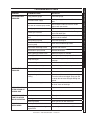
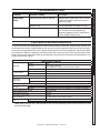
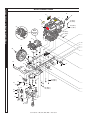
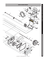
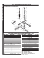
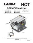
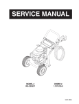
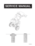
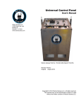
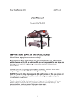
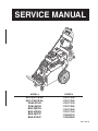
SERVICE MANUAL
MODEL #
ORDER #
HD 2.5/27 PB AL
HD 3.7/35 PB AL
PGA3-27324
PGA4-35324
BXA-252739
BXA-373539
BGA-252737
BGA-373537
1.107-132.0
1.107-133.0
1.107-127.0
1.107-128.0
1.107-120.0
1.107-121.0
1.106-057.0
1.106-058.0
8.917-991.0
CONTENTS
Exploded View ......................................................................................... 4
Exploded View Parts List ......................................................................5-7
M4035R.3 Pump Assembly Exploded and View .................................... 8
M4035R.3 Series Pump Exploded and Parts List...............................9-10
D3030R.1 Pump Assembly Exploded and View .................................. 11
D3030R.1 Series Pump Exploded and Parts List .............................12-13
Unloader Exploded and Parts List ......................................................... 14
Troubleshooting ................................................................................15-17
Preventive Manteinance ........................................................................ 17
Oil Change Record ................................................................................ 18
3
8.917-991.0 • HD, PGA, BXA, BGA • Rev. 01/12
PROBLEM
POSSIBLE CAUSE
SOLUTION
LOW OPERATING
PRESSURE
Faulty pressure gauge
Install new gauge.
Insufficient water supply
Use larger supply hose; clean filter at water
inlet.
Old, worn or incorrect spray nozzle
Match nozzle number to machine and/or
replace with new nozzle.
Belt slippage
Tighten or replace; use correct belt.
Plumbing or hose leak
Check plumbing system for leaks. Re-tape
leaks with teflon tape.
Faulty or mis-adjusted unloader
valve
Adjust unloader for proper pressure. Install
repair kit when needed.
Worn packing in pump
Install new packing kit.
Fouled or dirty inlet or discharge
valves in pump
Clean inlet and discharge valves.
Worn inlet or discharge valves
Replace with valve kit.
Obstruction in spray nozzle
Remove obstruction.
Leaking pressure control valve
Rebuild or replace as needed.
Slow engine RPM
Set engine speed at proper specifications.
Pump sucking air
Check water supply and possibility of air
seepage.
Valves sticking
Check and clean or replace if necessary.
Unloader valve seat faulty
Check and replace if necessary.
Worn or dirty pump valves
Call local distributor.
Nozzle is obstructed
Blow out or remove debris with fine needle.
Pump sucking air, inlet hose
leaking
Check that all hoses and fittings are airtight.
Turn off machine and trigger spray gun until
a steady flow of water emerges through the
nozzle.
Insufficient water supply
Turn water on full force. Check garden hose
for kinks, leaks or blockage.
PRESSURE LOW
AFTER PERIOD OF
NORMAL USE
Nozzle worn
Replace nozzle.
Unloader valve worn
Replace unloader valve.
ENGINE WILL NOT
START OR STOPS
WHILE OPERATING
Low oil shutdown
Fill engine with oil.
Out of gas
Fill fuel tank.
Water in gasoline
Drain gas tank; fill with clean fuel.
Nozzle partially blocked
Clean nozzle.
Excessive pressure from high
engine RPM
Adjust engine throttle to lower RPM.
FLUCTUATING
PRESSURE
ENGINE IS
OVERLOADED
PRESSURE WASHER Troubleshooting Guide
TROUBLESHOOTING
15
8.917-991.0 • HD, PGA, BXA, BGA • Rev. 01/12
PRESSURE WASHER Troubleshooting Guide
TROUBLESHOOTING
PROBLEM
POSSIBLE CAUSE
SOLUTION
WATER OR OIL
LEAKING FROM
BOTTOM OF PUMP
A small amount of leaking is
normal
If excessive leaking occurs, call local
distributor.
PRESENCE OF
WATER IN PUMP
OIL
Water sprayed at machine
Change oil. Direct spray away from machine.
High humidity in air
Check and change oil twice as often.
Piston packing worn. Oil seal worn.
Call local distributor.
Not enough gas or engine oil
Fill tank with gas. Check oil level.
Vapor lock developed by heat of day
Keep gas tank full to avoid vapor locking.
Obstruction in fuel filter
Clean or replace fuel filter.
ENGINE LACKS
POWER
Dirty air filter
Replace air filter.
ENGINE FALTERS
Choke is opened too soon
Move choke to halfway position until engine
runs smoothly.
WATER DRIPPING
FROM UNDER
PUMP
Piston packing worn
Call local distributor.
O-Ring plunger retainer worn
Call local distributor.
Cracked piston
Call local distributor.
OIL DRIPPING
FROM UNDER
PUMP
Oil seal worn or damaged
Call local distributor.
WATER LEAKING
FROM PUMP
PROTECTOR
Spray gun closed with machine
running 5 minutes or longer
Open spray gun or turn off machine.
Excess water supply pressure
Place a pressure regulator at end of 50'
garden hose.
NO DETERGENT
Detergent suction tube not properly
connected to machine
Check connection.
Detergent is too thick
Dilute detergent. For best results, use
manufacturers detergent.
Detergent filter valve is at lowest
setting
Set detergent filter valve to a higher setting.
Filter on detergent suction tube is
clogged
Run warm water through filter to remove
debris.
Damaged or clogged detergent suction tube
Remove obstruction or replace detergent
suction tube.
A high pressure nozzle is attached.
Replace with black detergent nozzle.
Discharge nozzle is obstructed
Blow out or remove debris with fine needle.
Loose fittings
Tighten fittings.
Missing/worn rubber washer
Insert new washer.
ENGINE OPERATES
FOR 15 MINUTES
THEN STOPS
GARDEN HOSE
CONNECTION
LEAKS
16
8.917-991.0 • HD, PGA, BXA, BGA • Rev. 01/12
PROBLEM
POSSIBLE CAUSE
SOLUTION
SPRAY WAND
LEAKS
Spray wand not properly attached
Slide the spray wand into the gun. Turn the
wand collar clockwise onto the spray gun
threads until tight.
Broken o-ring
Call local distributor and order an o-ring.
Pump is sucking air
Check that hoses and fittings are air tight.
Turn off machine and purge pump by
squeezing trigger gun until a steady flow of
water emerges through nozzle.
PUMP IS NOISY
PREVENTATIVE MAINTENANCE
This pressure washer was produced with the best available materials and quality craftsmanship. However, you
as the owner have certain responsibilities for the correct care of the equipment. Attention to regular preventative maintenance procedures will assist in preserving the performance of your equipment. Contact your dealer
for maintenance. Regular preventative maintenance will add many hours to the life of your pressure washer.
Perform maintenance more often under severe conditions. Check pump oil and engine oil level before first use
of your new pressure washer.
MAINTENANCE SCHEDULE
Daily
First month or 20 hours.
Every 100 hours or every 6 months after first month
Every 50 hours
Daily
Every 3 months or 50 hours
Inspect
Engine Oil
Air Cleaner/Filter
Change
Filter
Inspect
Clean
Engine Fuel Filter
Spark Plug
Maintenance
500 hours or 6 months
Inspect
Every 6 months or 100 hours
Change
Every year or 300 hours
Annually
Oil level daily
After first 50 hours, then every 500 hours or annually (or 3 months)
Every 6 months
Annually
Weekly
Annually (if there are any signs of wear)
Every 6 months
Every 6 months
Clean Fuel Tank(s)
Inspect
Change
Replace High Pressure Nozzle
Replace Quick Connects
Clean Water Screen/Filter
Replace HP Hose
Tighten
Belts*
Inspect/Replace
Pump Oil
PRESSURE WASHER Troubleshooting Guide
TROUBLESHOOTING
*Note: When servicing belts, don't exceed 14 lb-ft on pump mounting screws.Failure to do so will cause
pump thread damage.
17
8.917-991.0 • HD, PGA, BXA, BGA • Rev. 01/12
SERVICE MANUAL
PRESSURE WASHER
OIL CHANGE RECORD
Check pump oil and engine oil level before first use of your new pressure washer.
Date Oil Changed
Month/Day/Year
Estimated Operating
Hours Since Last
Oil Change
Date Oil Changed
Month/Day/Year
18
8.917-991.0 • HD, PGA, BXA, BGA • Rev. 01/12
Estimated Operating
Hours Since Last
Oil Change
SERVICE MANUAL
EXPLODED VIEW
87
75
62
71
1
PRESSURE WASHER
72
33
17 (389cc)
85 (196cc)
64 (389cc)
11 (196cc)
79
For
Detail
See Pump
Assy
64 (389cc)
11 (196cc)
65
33
21
36
82
25
74
34
81
57
6
15
30
29
14
78
23
22
11
14
50
11
15
22
32
13
31
10
64 (389cc)
86 (196cc)
56
16
24
49
63
66
68
16 (389cc)
14 (196cc)
14 11
26
66
27
14
44
11
56
67
60
69
4
8.917-991.0 • HD, PGA, BXA, BGA • Rev. 01/12
22
11
15
40
4
39
18
41
14
42
14
47
83
3
38
19
46
37
17
38
76
11
77
14
SERVICE MANUAL
3
70
PRESSURE WASHER
EXPLODED VIEW
37
43
2
55
5
14
11
11
14
15
12
59
52
45
64 (389cc)
11 (196cc)
17 (389cc)
84 (196cc)
66
51
35
9
20
8
61
48
21
7
6
36
58
54
28
73
80
53
5
8.917-991.0 • HD, PGA, BXA, BGA • Rev. 01/12
SERVICE MANUAL
EXPLODED VIEW PARTS LIST (CONT)
ITEM PART NO.
1
9.802-317.0
2
PRESSURE WASHER
8.750-580.0
8.917-978.0
Engine, Honda,
GX390UT2QA2 (389 cc)
Engine, Honda,
GX200UTQX2 (196 cc)
QTY
1
Handle Support Assy
Al Direct Drive
1
4
9.135-007.0
Rotary Tube-Joint
4
8.917-976.0
Handle Assy Al Direct Drive
1
5
8.750-303.0
Handle Stiffener Al
2
6
9.802-402.0
Bushing, H X 24MM
1
7
8.715-593.0
9.802-380.0
Pulley, 2BK 90 H (389 cc)
Pulley, BK 80 H (196 cc)
8
9.802-399.0
9.803-897.0
9
10
DESCRIPTION
QTY
30
8.919-349.0
8.919-401.0
Al Base Long (389 cc)
Al Base Short (196 cc)
31
8.919-352.0
Under-Frame Slider
1
32
8.919-354.0
Slider Stiffener Long
1
33
Pump Assy 2700 PSI
(See M4035R Specs Pages)
Pump Assy 3500 PSI
(See D3030R Specs Pages)
1
1
1
1
34
8.919-356.0
8.918-079.0
Axle Spacer RH 2.0" (389 cc)
Axle Spacer Silver (196 cc)
1
1
1
1
35
8.919-358.0
Axle Spacer Left 5.00"
1
36
9.802-782.0
Collar, 5/8" Bore Shaft
2
Bushing, H X 1 (389 cc)
Bushing, H X 3/4 (196 cc)
1
1
37
9.196-307.0
1/4-20 x 1-1/2 GR 2 Hex
Bolt Zinc
4
8.715-576.0
9.802-379.0
Pulley, 2BK 32 H (389 cc)
Pulley, BK 36 H (196 cc)
1
1
38
9.197-010.0
1/4-20 Nylon Insert Lock Nut
4
39
9.177-204.0
Sleeve rubber
4
9.802-740.0
Bolt, 1/2 X 3-1/2",
NC HH(615595)
1
11
8.718-980.0
Washer, 5/16" (389 cc)
(196 cc)
41
47
12
9.803-114.0
Retainer Bracket,
Handle, Black
2
9.802-816.0
9.802-813.0
14
ITEM PART NO.
1
3
13
9.802-776.0
Washer, 7/16",
Lock Split Ring (389 cc)
Washer, 5/16",
Lock Split Ring (196 cc)
40
8.712-345.0
8.712-346.0
8.712-347.0
4
8.712-348.0
4
Nylon Insert Nut 5/16" (389 cc) 27
(196 cc) 31
15
9.802-716.0
Bolt, 5/16" X 2"
10
16
9.197-003.0
3/8-16 Nylon Insert (389 cc)
(196 cc)
6
2
17
9.196-041.0
Hex Head Bolt
3/8-16 X 1-3/4 (389 cc)
(196 cc)
7
2
18
8.918-437.0
Holder Wand Left Silver
1
19
9.136-502.0
Knob
2
20
9.802-793.0
Nut, Cage, 1/4" X 16 GA
5
21
8.711-907.0
Wheel & Tire, 6.5" Steel Rim,
12.5 Tire (389 cc)
Wheel & Tire Assy,
10" Steel Rim (196 cc)
9.802-270.0
6
DESCRIPTION
2
2
22
9.802-710.0
Screw 5/16" x 1" NC
10
23
9.802-767.0
Screw, 3/8" X 3/4"
2
24
9.802-781.0
Nut, 3/8" NC, Whiz Loc Flange 2
25
9.802-811.0
Washer, 3/8" X 1-1/2" (389 cc) 4
26
9.802-066.0
Pad Soft Rubber
2
27
8.718-684.0
Bolt, 3/8" X 5"
2
28
9.802-754.0
Screw, 1/4" x 1/2" NC
5
29
8.919-712.0
Aluminium Bumper
1
8.712-331.0
8.712-333.0
8.712-334.0
8.712-335.0
Quick Connect
Nozzle Kit (389 cc)
Nozzle,
SAQCMEG 0004, RED
Nozzle,
SAQCMEG 1504, YELLOW
Nozzle,
SAQCMEG 2504, GREEN
Nozzle,
SAQCMEG 4004, WHITE
Quick Connect
Nozzle Kit (196 cc)
Nozzle,
SAQCMEG 0003, Red
Nozzle,
SAQCMEG 1503, Yellow
Nozzle,
SAQCMEG 2503, Green
Nozzle,
SAQCMEG 4003, White
1
1
41
8.718-625.0
Bolt, 5/16"-18X3/4", NC Crrge 1
42
9.802-712.0
Bolt, 5/16"-18 X 1-3/4",
NC Carriage
1
43
8.750-247.0
Trigger Gun Model M407
1
44
8.919-348.0
8.919-421.0
Al Foot Belt Drive (389 cc)
1
Al Foot Belt Drive Short(196 cc)1
45
8.908-395.0
8.919-422.0
Axle, 5/8" x 26.80" (389 cc)
1
Axle Short Base Al 24" (196 cc) 1
46
8.783-040.0
Wand 44" Zinc Plated,
Handle & Coupler (389 cc)
Wand 30" Zinc Plated,
Handle & Coupler (196 cc)
8.783-039.0
8.917-991.0 • HD, PGA, BXA, BGA • Rev. 01/12
1
1
ITEM PART NO.
47
8.916-740.0
8.739-011.0
8.739-021.0
8.739-026.0
QTY
Hose, 3/8" x 50',
1 Wire Tuff-Skin (BGA Models)
Hose, 3/8" x 50',
1 Wire Tuff-Skin (BXA Models)
Hose, 3/8" x 50',
1 Wire Tuff-Skin (HD Models)
Hose, 3/8" x 50',
1 Wire Tuff-Skin (PGA Models)
1
1
1
Belt, BX38 (389 cc)
Belt, BX34 (196 cc)
2
1
49
8.751-212.0
9.802-742.0
Bolt M10 X 25MM (389 cc)
Bolt, 8mm x 20mm (196 cc)
4
4
50
8.919-423.0
Axle Holder Al Frame
2
51
9.802-810.0
Washer Flat 5/8"
2
52
8.919-350.0
Al Back Beltguard
Long (389 cc)
Al Back Beltguard
Short(196 cc)
1
1
53
8.919-351.0
8.919-403.0
Front Beltguard Long (389 cc) 1
Front Beltguard Short (196 cc) 1
54
9.802-071.0
Al Trim, 750 B2 X 1/16
55
8.919-796.0
Hose Hanger Al Frames
1
56
9.802-809.0
Washer, 1/2" Flat
3
57
9.803-551.0
Screw, 5/16" x 3/4"
3
58
9.802-778.0
Nut, Whiz Loc 5/16 Flange
59
8.932-993.0
60
61
QTY
8.783-036.0
Label, Warning Pictogram
1
77
8.750-809.0
Label Operation
Warn Trilingual Small
1
78
8.783-038.0
Label, Universal DB Rating,
Ear Protection
1
1
79
9.800-008.0
Label, Danger Cool Engine
80
8.751-861.0
Label, Long
(HD Models) (389 cc)
1
Label, Short
(HD Models) (196 cc)
1
Label, Guard (PGA Models)
1
Label, Logo Red (BXA Models) 1
Label, Logo Die-Cut
(BGA Models)
1
8.751-862.0
8.750-465.0
8.704-654.0
8.900-870.0
81
8.901-219.0
Label, ETL, Mty, UL 1776
82
9.800-034.0
Label, Clear Lexan 4.3" X 5.5" 1
83
8.750-284.0
8.750-285.0
Label Name Plate (HD Models) 1
Label NamePlate
(PGA Models)
1
Label Name Plate
(BXA Models)
1
Label Name Plate
(BGA Models)
1
8.750-286.0
4.5 ft.
8.750-714.0
1
84
9.196-021.0
Socket Head Screw,
5/16''-24 x1.25'' (196 cc)
1
3
85
9.802-713.0
Bolt, 5/16" X 1-1/2" (196 cc)
1
Cushion, Pump
2
86
9.198-014.0
Washer 21/64 X 1" (196 cc)
1
9.802-819.0
Washer, 7/16" x 2 1/2"
2
87
8.919-425.0
Al Muffler Deflector (196 cc)
1
9.802-958.0
Key, 0.185
SQR X 1.75" (196 cc)
Key, 0.247
SQR X 2.125" (389 cc)
9.802-959.0
1
8.718-779.0
Scew, 4mm X 6 mm (196 cc)
63
8.919-592.0
Suspension Bracket
2
64
9.802-817.0
Washer, 3/8" x 1" (389 cc)
13
65
9.802-053.0
Bushing, Fuel Line, Rubber
1
66
8.736-004.0
Rubber Washer
1
67
8.719-091.0
Spring, Foot, Compression
2
68
8.706-557.0
Bellows, Leg (BOOT)
2
69
8.719-954.0
Tube, PC Foot Bolt
2
70
9.802-166.0
Coupler, 3/8" Socket,
Female, Brass
1
2
71
9.800-006.0
Label, Hot/Caliente W/Arrows 1
72
8.917-015.0
Label, Regulation 4442.6
1
73
8.901-137.0
Label, Beltguard Warning
1
74
8.930-124.0
Label, Intended For
Outdoor Use-Mexico
1
Label, Quick Start Guide
1
8.783-034.0
Not Shown
1
62
75
DESCRIPTION
76
1
9.802-417.0
8.715-695.0
8.919-402.0
ITEM PART NO.
SERVICE MANUAL
48
DESCRIPTION
PRESSURE WASHER
EXPLODED VIEW PARTS LIST (CONT)
7
8.917-991.0 • HD, PGA, BXA, BGA • Rev. 01/12
1
PRESSURE WASHER
D3030R.1 PUMP ASSEMBLY EXPLODED VIEW
SERVICE MANUAL
2
3
5
4
ITEM PART NO.
1
9.804-006.0
8.904-857.0
8.904-730.0
DESCRIPTION
Pump, KD3030R.1,
3@3000,1650 RPM
Pump, LD3030R.1,
3@3000, 1650 RPM
Pump, HD3030R.1,
3@3000, 1650 RPM
QTY
1
1
1
2
9.175-018.0
UU1 3500PSI,
Universal Unloader (SPARE)
3
9.804-025.0
Pump Protector, 1/4" 145 Deg 1
4
9.802-146.0
Swivel, 1/2" MP x 3/4"
GHF W/Strainer
1
Coupler, 3/8" Plug, Male
1
5
9.802-171.0
1
11
8.917-991.0 • HD, PGA, BXA, BGA • Rev. 01/12
SERVICE MANUAL
D.1 PUMP EXPLODED VIEW
PRESSURE WASHER
8.725-169.0 LD 3025R.1
8.904-857.0 LD 3030R.1
8.904-856.0 LD 4020R.1
TORQUE
SPECS
Item #
Ft.-lbs
14
65
17
18
25
7.6
34
7
44
13
LD.1 PUMP EXPLODED VIEW PARTS LIST
ITEM PART NO.
DESCRIPTION
1
ITEM PART NO.
DESCRIPTION
QTY
1
9.803-938.0
2*
See Kits Below Plunger Oil Seal
3
12* See Kits Below Valve Assembly
6
3*
See Kits Below O-Ring Ø1.78 x 28.30
3
13* 9.803-948.0
O-Ring Ø2.62 x 18.77
6
4*
See Kits Below Pressure Ring 15mm (3030)
3
14
9.803-949.0
Valve Plug
6
15
9.803-950.0
Copper Washer 1/4
1
16
9.803-951.0
Brass Plug G1/4
1
5*
Crankcase
QTY
See Kits Below Pressure Ring 18mm
(4020, 3025)
3
See Kits Below U-Seal, 15mm (3030)
3
See Kits Below U-Seal, 18mm
(4020, 3025)
6*
3
See Kits Below Intermediate Ring 15mm
(3030)
3
See Kits Below Intermediate 18mm
(4020, 3025)
3
See Kits Below Intermed. Ring 15mm
(3030)
3
See Kits Below Intermed. Ring 18mm
(4020, 3025)
3
8
9.802-926.0
Brass Plug 1/2"
1
9
9.803-199.0
Copper Washer 1/2"
1
10
9.803-946.0
Manifold Housing
1
7*
11* 9.803-947.0
O-Ring Ø1.78 x 15.54
6
17
9.803-952.0
Manifold Stud Bolt
8
18
9.802-884.0
Washer
8
19
9.803-198.0
Copper Washer 3/8
1
20
9.802-925.0
Brass Plug 3/8
2
25
9.802-939.0
Screw
12
26
9.803-953.0
Bearing Cover
2
27
9.803-954.0
Bearing Seal
1
28
9.802-914.0
Snap Ring
1
29
9.803-955.0
Ball Bearing
2
30
9.803-956.0
Crankshaft
1
31
9.803-167.0
Crankshaft Key
1
32
9.803-957.0
Oil Dipstick
1
12
8.917-991.0 • HD, PGA, BXA, BGA • Rev. 01/12
PRESSURE WASHER
LD.1 PUMP EXPLODED VIEW PARTS LIST
ITEM PART NO.
33
8.933-010.0
DESCRIPTION
QTY
Crankshaft Seal
1
34* See Kits Below Plunger Nut
3
35* See Kit Below
3
Copper Spacer
36* See Kits Below Plunger, 15mm (3030)
See Kits Below Plunger, 18mm
(4020, 3025)
3
3
37* See Kits Below Copper Spacer
3
3
3
40* See Kits Below Plunger Rod
3
41
9.803-965.0
Connecting Rod Pin
3
42
9.803-966.0
Connecting Rod
3
43
9.803-218.0
Spring Washer
6
44
8.933-020.0
Connecting Rod Screw
6
45
9.803-202.0
Sight Glass
1
46
9.803-197.0
Gasket
1
1
47
9.803-968.0
Crankcase Cover
48
9.803-969.0
O-Ring Ø2.62 x 107.62
SERVICE MANUAL
38* See Kits Below O-Ring Ø1.78 x 5.28
39* See Kits Below Teflon Ring
* Available in kit (See below)
REPAIR
KIT NUMBER
8.725-354.0
8.725-356.0
8.725-355.0
8.725-357.0
9.803-934.0
9.803-935.0
9.803-936.0
9.803-937.0
Plunger
Seal 15mm
D-3030
Plunger
Seal 18mm
D-3025
D-4020
Complete
Seal
Packing,
15mm
D-3030
Complete
Seal Packing, 18mm
D-3025
D-4020
Plunger
15mm
D-3030
Plunger
18mm
D-3025
D4020
Complete
Valve
Plunger Oil
Seals
3, 5, 7
3, 5, 7
3, 4, 5,
6, 7
3, 4, 5,
6, 7,
34, 35, 36,
37, 38
34, 35, 36,
37, 38
11, 12, 13
2
3
3
1
1
1
1
6
3
Kit Description
ITEM
NUMBERS
INCLUDED
NUMBER
OF CYLINDERS
KIT WILL
SERVICE
13
8.917-991.0 • HD, PGA, BXA, BGA • Rev. 01/12
9.175-018.0
UU1 3500PSI, UNIVERSAL UNLOADER (SPARE)
21
14
2
21
3
20
PRESSURE WASHER
SERVICE MANUAL
UU1 UNLOADER EXPLODED VIEW
10
16
18
5
1
15
19
6
27
7
25
23
25
4
24
8
22
27
28
26
13
26
15
9
12
17
27
23
11
UU1 UNLOADER EXPLODED VIEW PARTS LIST
ITEM PART #
1
KIT QTY
18
O-Ring Backup
6 x 1.45 x 1.68
A, D
1
1
19
Ball Housing Assy
C, D
1
1
20
O-Ring 6.75 x 1.78 BN80 A, D
1
1
21
Spring Seat
C, D
2
Plunger Spring
B
1
Piston
C, D
1
A, D
1
5
9.152-372.0 Piston Ring
KIT QTY
17
Piston O-Ring Back Up
8.749-796.0 Main Block
DESCRIPTION
1
3
4
ITEM PART #
D
2
D
1
Ball Seat
7
O-Ring 10.5 ID x 1.5 CS A,C,D
1
22
8
Plunger
B
1
23
8.917-699.0 Banjo Bolt 1/2" Short
8.917-700.0 Banjo Bolt 1/2"-1/4" NPT Short
C, D
1
24
8.917-698.0 Banjo Bolt 3/8" Short
1
25
9.802-893.0 Seal Washer 3/8"
2
26
9.803-921.0 Seal Washer 1/2"
9.802-893.0 Seal Washer 3/8"
2
2
9
C, D
9.149-006.0 Sliding Connector Guide
6
10
14
DESCRIPTION
8.751-394.0 Piston Housing
9.152-016.0 Plunger Housing
1
Bypass Spring
11
9.149-001.0 Low Pressure Port
1
12
9.152-017.0 Sliding Connector, 30mm
8.762-005.0 Sliding Connector, 40mm, Long
1
1
13
9.149-002.0 Sliding Connector H 1/2"
9.149-005.0 Sliding Connector H 3/8"
1
1
14
9.196-011.0 Plug 5/8 -18 UNF
D
1
15
O-Ring 12 ID x 2 CS
A, D
2
16
O-Ring 6 ID X 2 CS
A, D
1
27
28
Kit A
Kit B
Kit C
Kit D
O-Ring 15 ID x 2CS
8.706-865.0
9.104-038.0
9.104-039.0
9.104-040.0
8.920-045.0
8.917-991.0 • HD, PGA, BXA, BGA • Rev. 01/12
Plug, 1/4" Countersunk
O-Ring Repair Kit
Outlet Kit
Stem Basic Kit
UU1 Complete Stem Kit
1
1
A,B,D 3
1