1
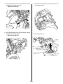
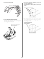
Accessory
Application
Publication No.
MII 14766
INSTALLATION
INSTRUCTIONS
ACCESSORY SOCKET
P/N 08U70-HR3-A20
After ‘13 TRX420 All
(Except ‘14 FA/FPA)
Issue Date
December 2013
TOOLS AND SUPPLIES REQUIRED
(1)
Rotary tool w/carbide burr
Power drill
25/64 inch (10 mm) drill bit
1-5/16 inch (33 mm) hole saw
Tape
(4)
TORQUE CHART
Refer to the Service Manual for the torque values of the
removed parts.
The holding nut is to be hand tightened.
USE AND CARE INFORMATION
(2)
• Read through instructions completely prior to
installation of the accessory socket.
• Check the accessor y mounts frequently and
retighten if necessary.
(3)
(5)
No.
Description
Qty
(1)
Accessory socket
1
(2)
Accessory socket trim (OUTER)
1
(3)
Accessory socket trim (INNER)
1
(4)
Accessory socket holding nut
1
(5)
Wire tie
1
SUB HARNESS
Sold separately P/N 08Z01-HR3-A20
The Accessory Socket requires the use of the
Accessory Sub Harness.
© 2013 Honda Motor Co., Ltd. - All Rights Reserved.
1 of 6
08U70-HR3-A20
1. Using the procedures in the Service Manual, remove
the right front assembly trim clips.
• Repeat on the left side.
3. Disconnect the headlight wiring harness from the
main wiring harness.
2. Using the procedures in the Service Manual, remove
the right front assembly bolts.
• Repeat on the left side.
4. Remove the fuel cap.
2 of 6
5. Remove the front assembly.
7. Drill the large hole with a 1-5/16 inch (33 mm) hole
saw at the indicated mark.
Drill two 25/64 inch (10 mm) holes at the indicated
marks.
Drill holes at the indicated marks.
8. After drilling the holes, use a rotary tool and carbide
burr to connect the circles by cutting along the dotted
line, making a window.
6. Cut out the cutting template from page 6.
From the under-side of the front assembly attach
the cutting template with tape.
Connect the circles by cutting
along the dotted line.
Attach supplied cutting template
with tape in this area.
3 of 6
9. Install the accessory socket:
Place the inner socket trim on the inside of the
fender. Place the outer socket trim on the outside of
the fender.
Insert the accessory socket through both trim
pieces and secure it with the socket nut.
10. Install the accessory sub harness to the Red 4-pin
connector and secure it to the clip/holder. Secure
the sub-harness with the provided wire tie as
shown.
EXISTING WIRE TIE
PROVIDED WIRE TIE
ACCESSORY SOCKET TRIM (OUTER)
ACCESSORY SOCKET
RED 4-PIN CONNECTOR
ACCESSORY SUB HARNESS
11. Temporarily reinstall the front fender assembly and
connect the accessory socket to the accessory sub
harness 2-pin connector. Test the accessory socket
operation.
ACCESSORY SOCKET NUT
12. Reinstall the removed parts.
ACCESSORY SOCKET TRIM (INNER)
10. Remove the dummy plug from the Red 4-pin
connector and disconnect it from its clip/holder.
Remove the dummy pug.
4 of 6
THIS PAGE LEFT BLANK
INTENTIONALLY
5 of 6
< CUTTING TEMPLATE >
Cut out along the outer
black line.
SCALE
SCALE
NOTICE
If you print this template from your local computer,
make sure the printer settings do not “scale” or
“shrink” the page.
6 of 6