1
Article No. 01-9-7
Emissions/Engine Controls - Driveability Diagnosis
05/14/01 – 14 mai 2001
Emissions/Engine Controls - Driveability Diagnosis
Index
- Information
- A. Description of Terms and Acronyms
- B. HO2S Location Diagrams
- C. Heated Oxygen Sensor (HO2S) Monitor
- D. Catalyst Efficiency Monitor
- E. Fuel System Monitor
- F. Diagnostic Service Tips
DRIVEABILITY - H025 (HEATED OXYGEN SENSOR),
CATALYST, AND FUEL SYSTEM MONITORS SERVICE TIPS - OBD II VEHICLES ONLY
FORD:
1994-1997 THUNDERBIRD
1994-2001 MUSTANG
1995-2001 CROWN VICTORIA
1996-1997 PROBE
1996-2000 CONTOUR
1996-2001 ESCORT, TAURUS
2000-2001 FOCUS
1994-1997 F SUPER DUTY, F-250 HD, F-350
1995-2001 ECONOLINE, RANGER, WINDSTAR
1996 BRONCO
1996-1997 AEROSTAR
1996-2001 EXPLORER
1997-2001 EXPEDITION, F-150, F-250 LD
1999-2001 SUPER DUTY F SERIES
2000-2001 EXCURSION
2001 ESCAPE
LINCOLN:
1995-2001 CONTINENTAL, TOWN CAR
1996-1998 MARK VIII
2000-2001 LS
1998-2001 NAVIGATOR
MERCURY:
1994-1997 COUGAR
1995-2001 GRAND MARQUIS
1996-1999 TRACER
1996-2000 MYSTIQUE
1996-2001 SABLE
1999-2001 COUGAR
1997-2001 MOUNTAINEER
ISSUE
This article is intended to be an aide in diagnosing conditions related to Heated Oxygen Sensor
(HO2S), Catalyst, and Fuel System Monitor related Diagnostic Trouble Codes (DTCs). Additional
information is included to assist in diagnosing certain vehicle symptoms. This article is NOT
intended to be a shortcut to the Powertrain Control/Emissions Diagnosis (PC/ED) Workshop
Manual pinpoint tests. The pinpoint tests in the PC/ED Manual should ALWAYS be followed when
diagnosing vehicle conditions.
ACTION
Use the following information and Service Tips to assist in the diagnosis of H025, Catalyst, and
Fuel System Monitor related DTCs.
OTHER APPLICABLE ARTICLES: 98-23-10
WARRANTY STATUS: INFORMATION ONLY
OASIS CODES: 623000, 690000, 698298
Article No. 01-9-7
Emissions/Engine Controls - Driveability Diagnosis
INFORMATION
- A.-Description of Terms and Acronyms
- B.-HO2S Location Diagrams
- C.-Heated Oxygen Sensor (HO2S) Monitor
- C1.-Heated Oxygen Sensor (HO2S) Monitor - Information
- C2.-Heated Oxygen Sensor (HO2S) Monitor - Diagnostic Trouble Codes (DTCs)
- D.-Catalyst Efficiency Monitor
- D1.-Catalyst Efficiency Monitor - Information
- D2.-Catalyst Efficiency Monitor - Diagnostic Trouble Codes (DTCs)
- E.-Fuel System Monitor
- E1.-Fuel System Monitor - Information
- E2.-Fuel System Monitor Diagnostic Trouble Codes (DTCs)
- F.-Diagnostic Service Tips
- F1.-Tips - General
- F2.-Tips Related to Heated Oxygen Sensor (HO2S) Monitor
- F3.-Tips Related to Catalyst Monitor
- F4.-Tips Related to Fuel System Monitor
Article No. 01-9-7
Emissions/Engine Controls - Driveability Diagnosis
A. DESCRIPTION OF TERMS AND ACRONYMS
- CHT - Cylinder Head Temperature Sensor or PID
- CKP - Crankshaft Position Sensor or PID
- DTC - Diagnostic Trouble Code
- ECT - Engine Coolant Temperature Sensor or PID
- EGR - Exhaust Gas Recirculation
- EEC - Electronic Engine Control
- EVR - EGR Vacuum Regulator
- FMEM - Failure Mode Effects Management
- GND - Ground
- HC - Hydrocarbons
- HO2S - Heated Oxygen Sensor or PID
- IAT - Inlet Air Temperature Sensor or PID
- KAM - Keep Alive Memory
- KOEO - Key On Engine Off
- KOER - Key On Engine Running
- LONGFT - Long Term Fuel Trim
- MAF – Mass Air Flow Sensor or PID
- MIL - Malfunction Indicator Lamp ("Check Engine")
- NGS - New Generation Star Tester (Scan Tool)
- OBD II – On-Board Diagnostics II
- OSM - Output State Monitor
- PC/ED - Powertrain Control/Emissions Diagnosis
- PCM - Powertrain Control Module
- PCV - Positive Crankcase Ventilation
- PID - Parameter Identification Display
- RAM - Random Access Memory
- RPM - Revolutions Per Minute
- SHRTFT - Short Term Fuel Trim
- Stoichiometric - 14.7:1 Air/Fuel Ratio (Gasoline Engines)
- TP - Throttle Position Sensor or PID
- VMV - Vapor Management Valve
- VPWR - Vehicle Power (Battery Voltage)
- VREF - Vehicle Reference Voltage (5 volts)
Article No. 01-9-7
B. HO2S LOCATION DIAGRAMS
Emissions/Engine Controls - Driveability Diagnosis
Article No. 01-9-7
Emissions/Engine Controls - Driveability Diagnosis
C. HEATED OXYGEN SENSOR (HO2S) MONITOR
C1.)-Heated Oxygen Sensor (HO2S) Monitor - Information
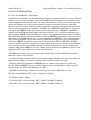
The H025 Monitor is an on-board strategy designed to monitor the HO2S sensors for a malfunction
or deterioration that can affect emissions. Under specific conditions, the fuel control or upstream
HO2S sensors (Figures 1 and 3) are checked for proper output voltage and response rate (the time it
takes to switch from lean to rich or rich to lean). Downstream HO2S sensors (Figures 1 and 3) used
for Catalyst Monitor are also monitored for proper output voltage. Input is required from the ECT
or CHT, IAT, MAF, TP and CKP sensors to activate the H025 Monitor. The Fuel System Monitor
and Misfire Detection Monitor must also have completed successfully before the HO2S Monitor is
enabled.
The HO2S sensor senses the oxygen content in the exhaust flow and outputs a voltage between zero
and 1.0 volt. Lean of stoichiometric (air/fuel ratio of approximately 14.7:1 for gasoline engines), the
HO2S will generate a voltage between zero and 0.45 volt. Rich of stoichiometric, the HO2S will
generate a voltage between 0.45 and 1.0 volt.
- The HO2S Monitor evaluates both the upstream (Fuel Control) and downstream (Catalyst Monitor)
HO2S for proper function.
- Once the HO2S Monitor is enabled, the upstream H025 signal voltage amplitude and response
frequency are checked. Excessive voltage is determined by comparing the HO2S signal voltage to a
maximum calibratable threshold voltage.
- A fixed frequency closed loop fuel control routine is executed and the upstream HO2S voltage
amplitude and output response frequency are observed. A sample of the upstream HO2S signal is
evaluated to determine if the sensor is capable of switching or has a slow response rate.
- An HO2S heater circuit fault is determined by turning the heater on and off and looking for a
corresponding change in the OSM and by measuring the current going through the heater circuit.
- The MIL is activated after a fault is detected on two consecutive OBD II drive cycles.
The HO2S Monitor DTCs can be categorized as follows:
- HO2S signal circuit malfunction - P0131, P0136, P0151, P0156
- HO2S slow response rate - P0133, P0153
- HO2S heater circuit malfunction - P0135, P0141, P0155, P0161
- Downstream HO2S not running in on-demand self test - P1127
- Swapped H025 connectors - P1128 and P1129
- H025 lack of switching - P1130, P1131, P1132, P1150, P1151, P1152
- HO2S lack of switching (sensor indicates lean) - P1137
- H025 lack of switching (sensor indicates rich) - P1138
C2.)-Heated Oxygen Sensor (HO2S) Monitor - Diagnostic Trouble Codes
Article No. 01-9-7
Emissions/Engine Controls - Driveability Diagnosis
D. CATALYST EFFICIENCY MONITOR
D1.)-Catalyst Efficiency Monitor - Information
The Federal Test Procedure Catalyst Monitor monitors for deterioration in the catalyst system and
illuminates the MIL when tailpipe emissions exceed the appropriate HC emission thresholds. The
Catalyst Monitor is enabled after the upstream and downstream HO2S sensors have been tested and
verified to be functional. This monitor relies on the front and rear heated oxygen sensors (HO2S) to
infer catalyst efficiency based upon oxygen storage capacity. Under normal closed loop fuel
conditions, high efficiency catalysts have oxygen storage which makes the switching frequency of
the rear HO2S quite slow compared with the frequency of the front HO2S. As catalyst efficiency
deteriorates, its ability to store oxygen declines, and the rear HO2S begins to switch more rapidly,
approaching the frequency of the front sensor. In general, as catalyst efficiency decreases, the
switch ratio increases from a switch ratio of 0 for a low mileage catalyst to a switch ratio of 0.8 or
0.9 for a low efficiency catalyst.
Some vehicles will monitor substantially less than the entire catalyst volume in order to meet the
stringent catalyst monitoring malfunction thresholds. In many cases, only the front, light-off
catalyst is monitored.
Front and rear HO2S switches are counted under specified closed loop fuel conditions. After the
required number of front switches are obtained, a rear-to-front HO2S switch ratio is calculated. The
switch ratio is compared against a threshold value. If the switch ratio is greater than the calibrated
maximum limit, the catalyst has failed. The test entry conditions for the Catalyst Efficiency Monitor
are as follows: ECT or CHT (warmed engine), IAT (not at extreme ambient temperatures), MAF
(greater than minimum engine load), VSS (within vehicle speed window) and TP (at part throttle)
are required.
- Because an exponentially weighted moving average is used for malfunction determination, up to
six OBD II drive cycles may be required to illuminate the MIL.
NOTE THE CATALYST MONITOR ON SOME EARLY OBD II VEHICLES (SOME 1994-1996
VEHICLES) WAS REFERRED TO AS THE "STEADY-STATE CATALYST MONITOR" AS
OPPOSED TO THE "FTP CATALYST MONITOR" (DESCRIBED ABOVE) THAT IS MOST
COMMON FOR VEHICLES BUILT AFTER 1996. BELOW IS A BRIEF DESCRIPTION OF
THE STEADY-STATE CATALYST MONITOR:
The Steady-State Catalyst Monitor performs a 20 second test during steady state rpm and load
conditions. The Monitor transfers closed loop fuel control from the front to the rear 02 sensors. The
Monitor then observes the switching frequency and compares it to a threshold frequency stored in
an rpm/load table. A frequency higher than the maximum calibrated threshold indicates a
malfunction.
The Catalyst Monitor DTCs can be categorized as follows:
- Catalyst system efficiency below threshold (Bank 1) - P0420
- Catalyst system efficiency below threshold (Bank 2) - P0430
D2.)-Catalyst Efficiency Monitor - Diagnostic Trouble Codes
Article No. 01-9-7
Emissions/Engine Controls - Driveability Diagnosis
E. FUEL SYSTEM MONITORE1.)-Fuel System Monitor - Information
The Fuel System Monitor is an on-board strategy designed to monitor the fuel trim system. The fuel
control system uses fuel trim tables stored in the PCM's KAM to compensate for variability in fuel
system components due to normal wear and aging. Fuel trim tables are based on vehicle speed and
engine load. During closed loop vehicle operation, the fuel trim strategy learns the corrections
needed to correct a "biased" rich or lean fuel system. The correction is stored in the fuel trim tables.
The fuel trim has two means of adapting; a LONGFT and a SHRTFT. LONGFT relies on the fuel
trim tables and SHRTFT refers to the desired air/fuel ratio parameter "LAMBSE". LAMBSE is
calculated by the PCM from HO2S inputs and helps maintain a 14.7:1 air/fuel ratio during closed
loop operation. SHRTFT and LONGFT work together. If the HO2S indicates the engine is running
rich, the PCM will correct the rich condition by moving SHRTFT in the negative range (less fuel to
correct for a rich combustion). If after a certain amount of time SHRTFT is still compensating for a
rich condition, the PCM "learns" this and moves LONGFT into the negative range to compensate
and allows SHRTFT to return to a value near 0%. Input from the ECT or CHT, IAT, and MAF
sensors is required to activate the fuel trim system, which in turn activates the Fuel System Monitor.
Once activated, the Fuel System Monitor looks for the fuel trim tables to reach the adaptive clip
(adaptive limit) and LAMBSE to exceed a calibrated limit. The Fuel System Monitor will store the
appropriate DTC when a fault is detected as described below.
- The H025 detects the presence of oxygen in the exhaust and provides the PCM with feedback
indicating a rich or lean condition.
- A correction factor is added to the fuel injector pulsewidth calculation according to the Long and
Short Term Fuel Trims as needed to compensate for variations in the fuel system.
- When deviation in the parameter LAMBSE increases, air/fuel control suffers and emissions
increase. When LAMBSE exceeds a calibrated limit and the fuel trim table has clipped (reached
adaptive limit), the Fuel System Monitor sets a DTC.
- The MIL is activated after a fault is detected on two consecutive OBD II drive cycles.
The Fuel System Monitor DTCs can be categorized as follows:
- Fuel Delivery Error - P0148
- Lean shift in fuel system operation - P0171 (Bank 1) and P0174 (Bank 2)
- Rich shift in fuel system operation - P0172 (Bank 1) and P0175 (Bank 2)
E2.)-Fuel System Monitor - Diagnostic Trouble Codes
Article No. 01-9-7
Emissions/Engine Controls - Driveability Diagnosis
F. DIAGNOSTIC SERVICE TIPS
1. Always reset KAM after performing a repair:
After performing a repair on a vehicle with the MIL on, and/or DTCs present, always clear KAM.
When a malfunction is present, the PCM adapts (attempts to correct) for this condition. Once the
vehicle has been repaired, if the KAM is not reset, the PCM will once again have to adapt back to
the normal operating conditions. Clearing the KAM will erase what the PCM has learned, so the
PCM will be able to start with "base tables".
2. Always view and record Freeze Frame Data:
Freeze Frame Data can be a valuable asset in duplicating and diagnosing concerns. This data (a
snapshot of certain PID values, recorded at the time the MIL was activated) indicates the manner in
which the vehicle was being driven at the time the fault occurred. This can be especially useful on
intermittent concerns. Freeze Frame Data, in some cases, can also help to isolate possible areas of
concern, as well as ruling out others. Always record (write down) the Freeze Frame Data.
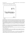
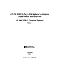
3. Multiple DTCs (with the same meaning):
When multiple (paired) DTCs with the same meaning are set for multiple sensors, it is unlikely that
replacing both HO2S sensors will resolve the concern. In most cases, there will be another issue that
is causing the codes. Examples of multiple (paired) DTCs:
(P0135/P0155), (P0141/P0161), (P1131/P1151), (P1132/P1152).
To further clarify this, see the more detailed scenario as follows:
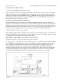
A vehicle comes in with a MIL On concern. KOEO self test reveals DTCs P0135 and P0155 (HTR11 and HTR-21 circuit malfunction), with no other DTCs present. The most likely cause of these
DTCs would be something in the heater power circuit that both of these HO2S sensors have in
common (Example: open or shorted heater circuit wiring or splice). It is highly unlikely that
multiple sensors would fail at the same time. When multiple DTCs of this nature are encountered,
reviewing the appropriate wiring diagram(s) can help to isolate possible areas of concern. When
reviewing the wiring diagram, look for things that the affected sensors have in common.
In this example, the most likely cause of DTCs P0135 and P0155 (with no other DTCs present)
would be a concern with Splice "B" (refer to Figure 2).
NOTE THIS ILLUSTRATION IS ONLY AN EXAMPLE. SPLICE NAMES "A", "B", AND "C"
ARE USED IN THIS EXAMPLE FOR CONVENIENCE ONLY. ON AN ACTUAL VEHICLE,
SPLICE NAMES WILL DEPEND ON THE CIRCUIT NUMBER FOR THE VEHICLE UNDER
REPAIR. NOTE ALSO THAT THIS FIGURE IS NOT INTENDED TO SHOW ALL
SPLICES/CONNECTIONS ON ALL VEHICLES. OTHER EEC CIRCUITS, NOT SHOWN,
MAY ALSO BE SPLICED IN WITH THE CIRCUITS SHOWN.
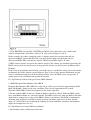
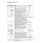
4. View H025 PID data carefully: NGS PIDs for HO2S sensors that do not exist (with certain
exhaust configurations) will show a value of "0" volts (refer to Figures 3 and 4).
In this example, the vehicle (equipped with a 4-cylinder engine) has one upstream and one
downstream HO2S. Notice that the NGS (scan tool) display shows two upstream and two
downstream HO2S PIDs, and that the "unused" HO2S sensor PIDs display "0" volts.
5. H025 sensors measure oxygen in the exhaust, not fuel: The exhaust gas condition reported by the
HO2S sensor is based on the presence of oxygen in the exhaust, not the presence of unburned fuel.
Example:
In the event of an ignition-related misfire, you might expect a rich HO2S reading, due to the amount
of unburned fuel in the exhaust system. However, there is also a large amount of unburned oxygen,
since no combustion took place in the misfiring cylinder. Since the H025 senses oxygen only, it
would report a lean condition in this particular situation.
F2.) Tips Related to Heated Oxygen Sensor (H025) Monitor
1. OBD II Response Rate Monitor: The OBD II
Response Rate Monitor (P0133/P0153) is only run at vehicle speeds between approximately 50-95
km/h (30-60 mph), during steady-state conditions. The test lasts approximately 6 seconds.
Therefore, P0133/P0153 cannot be diagnosed at idle in the repair bay.
2. Do not compare H025 switch rate - Bank-to-Bank or vehicle-to-vehicle: Different H025 switch
rates, from Bank-to-Bank, are considered normal. The H025 switch rate, from one Bank to the other,
should not be compared as a gauge of the H025's ability to switch/react. The PCM is continuously
adjusting spark and fuel in reaction to engine operating conditions (rpm, load, air flow, throttle
angle, etc.). The PCM is also continuously adapting to certain conditions (customer driving habits,
engine and component wear, etc.).
F3.) Tips Related to Catalyst Efficiency Monitor
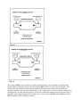
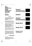
1. Determining catalyst efficiency/switch ratio:
The upstream H025 sensors will have a high switch frequency, due to normal closed loop fuel
control. With an efficient catalyst, the downstream H025 will have a low switch frequency. The
switch ratio is determined by dividing the number of downstream switches by the number of
upstream switches over a given period of time. As the catalyst ages (or if the catalyst is damaged or
contaminated), the downstream switches will increase. When the downstream switch rate crosses a
threshold value (approximately 0.75 switch ratio), a code is stored (P0420 and/or P0430) and the
MIL illuminates (refer to Figures 5 and 6).
NOTE IF A CATALYST IS DETERMINED TO HAVE LOW EFFICIENCY AND REQUIRES
REPLACEMENT, REPLACEMENT OF THE DOWNSTREAM H025 SENSORS WILL NOT BE
NECESSARY.
2. Use care in handling H025 sensors: In the event of catalyst replacement, use care in the handling
of H025 sensors to prevent damage or contamination. Do not use power tools in the removal or
installation of sensors. Use a 22mm wrench or crow foot to remove and install H025 sensors; do not
use slotted sockets, as these sockets may damage wires. H025 sensors should be torqued to 41 +/- 5
N.m (30 +/- 4 lb-ft).
3. Do not replace downstream HO2S sensors (H02S12/H02S22) for DTCs P0420 and/or P0430:
When diagnosing a vehicle with a customer concern of MIL On and DTCs P0420/P0430 in
continuous memory, do not replace the downstream HO2S sensors (H02S12/H02S22). Damaged or
malfunctioning downstream HO2S sensors will not cause these DTCs to be set. Always verify the
vehicle concern, then perform the pinpoint diagnostics in the appropriate PC/ED Service Manual.
F4.) Tips Related to the Fuel System Monitor
1. HO2S sensors are not likely to be the cause of adaptive DTCs P0171, P0172, P0174, P0175:
Most warranty-returned HO2S sensors (replaced for these DTCs) are found to function normally.
Additional related DTCs will normally be present if there is a concern with the HO2S sensors. Do
not replace an HO2S sensor unless verified through pinpoint diagnostic tests found in the PC/ED
Service Manual.
2. DTCs P0171, P0172, P0174, and P0175 are not related to downstream H028 sensors: When
diagnosing a vehicle with a MIL On and DTC(s) P0171, P0172, P0174, and/or P0175 in continuous
memory, do not replace the downstream HO2S sensors. These DTCs have no connection to the
downstream HO2S sensor function nor its diagnosis for faults. Always verify the vehicle concern,
then perform the pinpoint diagnostics from the appropriate PC/ED Service Manual.
3. Diagnosing lean conditions and lean DTCs P0171, P0174: Freeze Frame Data can often help to
identify the type of lean condition, even if the fault is intermittent, by indicating how the vehicle
was being driven when the fault occurred. Diagnosis of lean conditions and lean adaptive DTCs can
be difficult, especially if the concern is intermittent. Verifying the concern is extremely important.
There are different types of lean conditions. The ability to identify the type of lean condition
causing the concern can be crucial to a correct diagnosis. When DTCs P0171 and P0174 are both
present, there is a strong likelihood of another concern being present:
a. Vacuum leaks/unmetered air: In this type of condition, the engine may actually run lean of
stoichiometry (14.7:1 air/fuel ratio) if the PCM is not able to compensate enough to correct for
the condition. This condition is typically caused by air entering the engine through an abnormal
source (opening), or due to a MAF malfunction. In this situation, the volume of air entering the
engine is actually greater than what the MAF is indicating to the PCM. Vacuum leaks will
normally be most apparent when high manifold vacuum is present, during idle or light throttle.
If Freeze Frame Data indicates that the fault occurred at idle, a check for vacuum
leaks/unmetered air when the engine is cold might be the best starting point.
Examples: Loose, leaking or disconnected vacuum lines, intake manifold gaskets or 0-rings,
throttle body gaskets, brake booster, air inlet tube, stuck/frozen/aftermarket PCV valve,
unseated engine oil dipstick, MAF reading lower than normal, etc.
b. Insufficient fueling: In this type of condition, the engine may actually run lean of
stoichiometry (14.7:1 air/fuel ratio) if the PCM is not able to compensate enough to correct for
the condition. This condition is typically caused by a fuel delivery system concern that restricts
or limits the amount of fuel being delivered to the engine. This condition will normally be most
apparent when the engine is under a heavy load, when a higher volume of fuel is required. If
Freeze Frame Data indicates that the fault occurred under a heavy load, a check of the fuel
delivery system (checking fuel pressure with engine under a load) might be the best starting
point.
Examples: Low fuel pressure (fuel pump, fuel filter, fuel leaks, restricted fuel supply lines), fuel
injector concerns, etc.
c. Exhaust system leaks: In this type of condition, the engine may actually be running near
stoichiometry (14.7:1 air/fuel ratio), but the exhaust gas mixture will be lean. This condition is
caused by oxygen-rich air entering the exhaust system through an external source. This
condition will cause the exhaust gas mixture to be lean, even though the actual combustion in
the engine may not be.
Examples: Exhaust system leaks upstream or near HO2S, malfunctioning Secondary Air
Injection system
d. MAF concerns: If a MAF concern is suspected, see TSB 98-23-10.
4.-Checking fuel pressure: Check fuel pressure with engine under a load when diagnosing a lean
concern. A partially plugged fuel filter can be difficult to detect and can be easily overlooked if fuel
pressure is only checked at idle. The same is true for other types of fuel supply concerns (e.g., bent
or kinked lines, degraded fuel pump).
At idle, an engine requires only a small volume of fuel. Due to the fact that there is a small volume
of fuel needed at idle, a restriction in the fuel supply line in many cases will not cause the fuel
pressure to be low. When the vehicle is under a load, the engine requires much more fuel than at
idle. Under a load, a restriction in the fuel supply line will prevent the high rate of fuel flow that is
needed to maintain the correct fuel pressure.