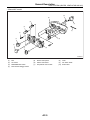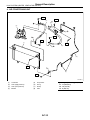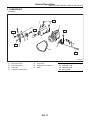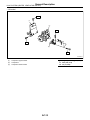
1
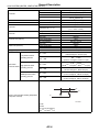
2004 LEGACY SERVICE MANUAL
QUICK REFERENCE INDEX
BODY SECTION
This service manual has been prepared
to provide SUBARU service personnel
with the necessary information and data
for the correct maintenance and repair
of SUBARU vehicles.
This manual includes the procedures
for maintenance, disassembling, reassembling, inspection and adjustment of
components and diagnostics for guidance of experienced mechanics.
Please peruse and utilize this manual
fully to ensure complete repair work for
satisfying our customers by keeping
their vehicle in optimum condition.
When replacement of parts during
repair work is needed, be sure to use
SUBARU genuine parts.
All information, illustration and specifications contained in this manual are
based on the latest product information
available at the time of publication
approval.
FUJI HEAVY INDUSTRIES LTD.
HVAC SYSTEM
(HEATER, VENTILATOR AND A/C)
AC
HVAC SYSTEM (AUTO A/C)
(DIAGNOSTICS)
AC(diag)
AIRBAG SYSTEM
AB
AIRBAG SYSTEM (DIAGNOSTICS)
AB(diag)
SEAT BELT SYSTEM
SB
LIGHTING SYSTEM
LI
WIPER AND WASHER SYSTEMS
WW
ENTERTAINMENT
ET
COMMUNICATION SYSTEM
COM
GLASS/WINDOWS/MIRRORS
GW
BODY STRUCTURE
BS
INSTRUMENTATION/DRIVER INFO
IDI
SEATS
SE
SECURITY AND LOCKS
SL
SUNROOF/T-TOP/CONVERTIBLE TOP
(SUNROOF)
SR
EXTERIOR/INTERIOR TRIM
EI
EXTERIOR BODY PANELS
EB
G2320GE7
2003 LEGACY SERVICE MANUAL
QUICK REFERENCE INDEX
BODY SECTION
CRUISE CONTROL SYSTEM
CC
CRUISE CONTROL SYSTEM
(DIAGNOSTICS)
CC(diag)
IMMOBILIZER (DIAGNOSTICS)
IM(diag)
LAN SYSTEM (DIAGNOSTICS)
LAN(diag)
G2320GE7
HVAC SYSTEM
(HEATER, VENTILATOR AND A/C)
AC
1.
2.
3.
4.
5.
6.
7.
8.
9.
10.
11.
12.
13.
14.
15.
16.
17.
18.
19.
20.
21.
22.
23.
24.
25.
26.
27.
28.
Page
General Description ....................................................................................2
Refrigerant Pressure with Manifold Gauge Set.........................................19
Refrigerant Recovery Procedure...............................................................20
Refrigerant Charging Procedure ...............................................................21
Refrigerant Leak Check ............................................................................24
Compressor Oil .........................................................................................25
Blower Motor Unit Assembly .....................................................................26
Blower Motor .............................................................................................27
Power Transistor (Auto A/C Model) ..........................................................28
Blower Resistor (Manual A/C Model) ........................................................29
Heater Core...............................................................................................30
Control Unit (Manual A/C Model) ..............................................................31
Control Unit (Auto A/C Model)...................................................................32
Compressor...............................................................................................33
Condenser.................................................................................................35
Heater and Cooling Unit............................................................................36
Evaporator.................................................................................................37
Hose and Tube..........................................................................................38
Relay and Fuse .........................................................................................39
Pressure Switch (Triple Pressure Switch).................................................40
Ambient Sensor (Auto A/C Model) ............................................................41
Sunload Sensor (Auto A/C Model) ............................................................42
In-Vehicle Sensor (Auto A/C Model) .........................................................43
Air Vent Grille ............................................................................................44
Heater Duct ...............................................................................................45
Heater Vent Duct.......................................................................................46
Heater Cock Solenoid Valve .....................................................................47
General Diagnostic Table..........................................................................48
General Description
HVAC SYSTEM (HEATER, VENTILATOR AND A/C)
1. General Description
A: SPECIFICATION
1. HEATER SYSTEM
Item
Specification
On condition
• Mode selector switch: HEAT
• Temperature control switch: FULL HOT
• Temperature difference between hot water
and inlet air: 65°C (149°F)
• Hot water flow rate: 360 2 (95.1 US gal,
79.2 Imp gal)/h
Heating capacity
5.2 kW (4,471 kcal/h,
17,743 BTU/h) or more
Air flow rate
370 m3 (13,066 cu ft)/h
Heat mode (FRESH), FULL HOT at 12.5 V
460 m3 (16,245 cu ft)/h
• Temperature control switch: FULL COLD
• Blower fan speed:
Auto A/C: 6th position
Manual A/C: 4th position
• Mode selector lever: RECIRC
Max air flow rate
264 × 110 × 27 mm
(10.4 × 4.33 × 1.06 in)
Magnet motor 220 W or less
Sirocco fan type
150 × 75 mm (5.91 × 2.95 in)
Heater core size
(height × length × width)
Type
Blower motor
Fan type and size
(diameter × width)
—
12 V
—
2. A/C SYSTEM
• Auto A/C model
Item
Type of air conditioner
Cooling capacity
Refrigerant
Compressor
Magnet clutch
Type
Discharge
Max. permissible speed
Type
Power consumption
Type of belt
Pulley dia. (effective dia.)
Pulley ratio
Type
Condenser
Core thickness
0.186 m2 (2.002 sq ft)
16 mm (0.63 in)
Radiation area
5.49 m2 (59.09 sq ft)
Core face area
Receiver drier
Effective inner capacity
Expansion valve
Type
Type
Evaporator
Dimensions (W × H × T)
Blower fan
Specification
Reheat air-mix type
5.3 kW
(4,557 kcal/h, 18,084 BTU/h)
HFC-134a (CH2FCF3)
[0.4±0.03 kg (0.88±0.07 lb)]
Scroll, constant volume (SCSA 08C)
74.5 cc (4.55 cu in)/rev
9,000 rpm
Dry, single-disc type
35 W
H4 model: V-belt 4 PK
H6 model: V-belt 6 PK
93 mm (3.7 in)
1.43
Corrugated fin (Sub cool type)
Fan type
Outer diameter × width
Power consumption
AC-2
190 cm3 (11.6 cu in)
Internal equalizing
Single tank
298.6 × 151 × 38 mm
(11.76 × 5.94 × 1.50 in)
Sirocco fan
150 × 75 mm (5.91 × 2.95 in)
220 W
General Description
HVAC SYSTEM (HEATER, VENTILATOR AND A/C)
Motor type
Magnet
H4 model: 90 W
H6 model: 160 W
H4 model: 300 mm (11.8 in)
H6 model: 320 mm (12.6 in)
Magnet
H4 model: 90 W
H6 model: 160 W
H4 model: 300 mm (11.8 in)
H6 model: 320 mm (12.6 in)
800±100 rpm
196±20 kPa
(2.00±0.20 kg/cm2, 28.4±2.9 psi)
Power consumption
Condenser fan (Sub fan)
Fan outer diameter
Motor type
Power consumption
Radiator fan (Main fan)
Fan outer diameter
Idling speed (A/C ON)
MPFI model
ON → OFF
Low-pressure switch
operating pressure
Triple switch
High-pressure switch
(Pressure switch) operating pressure
Middle-pressure switch
operating pressure
225+25−29 kPa
OFF → ON
(2.29+0.25−0.30 kg/cm2, 32.6+3.6−4.2 psi)
3,140+50−200 kPa
ON → OFF
(32.02+0.51−2.04 kg/cm2, 455.4+7.25−29.0 psi)
2,550±200 kPa
(26.00±2.04 kg/cm2, 369.8±29.0 psi)
1,370±120 kPa
(13.97±1.22 kg/cm2, 198.65±17.35 psi)
1,770±100 kPa
(18.05±1.02 kg/cm2, 256.81±14.50 psi)
OFF → ON
ON → OFF
OFF → ON
(3)
(1)
Thermo-control amplifier working temperature
(Evaporator outlet air)
(2)
(4)
AC-00601
(1) ON
(2) OFF
(3) 1±0.5°C (33.8±0.9°F)
(4) 4+1.50°C (39.2+2.70°F)
• Manual A/C model
Item
Type of air conditioner
Cooling capacity
Refrigerant
Compressor
Magnet clutch
Type
Discharge
Max. permissible speed
Type
Power consumption
Type of belt
Pulley dia. (effective dia.)
Pulley ratio
AC-3
Specification
Reheat air-mix type
5.3 kW (4,557 kcal/h, 18,084 BTU/h)
HFC-134a (CH2FCF3)
[0.4±0.03 kg (0.88±0.07 lb)]
Scroll, constant volume (SCSA 08C)
74.5 cc (4.55 cu in)/rev
9,000 rpm
Dry, single-disc type
35 W
V-belt 4 PK
93 mm (3.7 in)
1.43
General Description
HVAC SYSTEM (HEATER, VENTILATOR AND A/C)
Type
Corrugated fin (Sub cool type)
Core thickness
0.186 m2 (2.002 sq ft)
16 mm (0.63 in)
Radiation area
5.49 m2 (59.09 sq ft)
Core face area
Condenser
Receiver drier
Effective inner capacity
Expansion valve
Type
Type
Evaporator
Dimensions (W × H × T)
Blower fan
Condenser fan (Sub fan)
Radiator fan (Main fan)
Idling speed (A/C ON)
250 cm3 (15.26 cu in)
Externally equalizing
Single tank
298.6 × 151 × 38 mm
(11.7 × 5.94 × 1.50 in)
Sirocco fan
150 × 75 mm (5.91 × 2.95 in)
220 W
Magnet
90 W
300 mm (11.8 in)
Magnet
90 W
300 mm (11.8 in)
800±100 rpm
196±20 kPa
(2.00±0.20 kg/cm2, 28.4±2.9 psi)
Fan type
Outer diameter × width
Power consumption
Motor type
Power consumption
Fan outer diameter
Motor type
Power consumption
Fan outer diameter
MPFI model
ON → OFF
Low-pressure switch
operating pressure
Triple switch
High-pressure switch
(Pressure switch) operating pressure
Middle-pressure switch
operating pressure
225+25−29 kPa
OFF → ON
(2.29+0.25−0.30 kg/cm2, 32.6+3.6−4.2 psi)
3,140+50−200 kPa
ON → OFF
(32.02
+0.51
−2.04
kg/cm2, 455.4+7.25−29.0 psi)
2,550±200 kPa
(26.00±2.04 kg/cm2, 369.8±29.0 psi)
1,370±120 kPa
(13.97±1.22 kg/cm2, 198.65±17.35 psi)
1,770±100 kPa
(18.05±1.02 kg/cm2, 256.81±14.50 psi)
OFF → ON
ON → OFF
OFF → ON
(3)
(1)
Thermo control amplifier working temperature
(Evaporator outlet air)
(2)
(4)
AC-00601
(1) ON
(2) OFF
(3) 1±0.5°C (33.8±0.9°F)
(4) 4+1.50°C (39.2+2.70°F)
AC-4
General Description
HVAC SYSTEM (HEATER, VENTILATOR AND A/C)
B: COMPONENT
1. HEATER COOLING UNIT
• Auto A/C model
(10)
(12)
(11)
(9)
(8)
(13)
T
(14)
(7)
(6)
(5)
T
(4)
(15)
(16)
(3)
(17)
(1)
(2)
AC-00906
(1)
(2)
(3)
(4)
(5)
(6)
(7)
Foot duct (RH)
Evaporator center
Pipe cover
Evaporator cover
Expansion valve
Packing
Evaporator
(8)
(9)
(10)
(11)
(12)
(13)
(14)
Mix actuator
Mode actuator
Heater pipe clamp
Heater core
Heater core cover
Aspirator
Aspirator hose
AC-5
(15)
(16)
(17)
Foot duct (LH)
Unit ASSY
Drain hose
Tightening torque: N⋅m (kgf-m, ft-lb)
T: 7.5 (0.76, 5.5)
General Description
HVAC SYSTEM (HEATER, VENTILATOR AND A/C)
• Manual A/C model
(11)
(13)
(12)
(10)
(9)
T
(8)
(7)
(6)
(5)
T
(4)
(14)
(15)
(3)
(1)
(16)
(2)
AC-00907
(1)
(2)
(3)
(4)
(5)
(6)
(7)
Foot duct (RH)
Thermo amplifier
Pipe cover
Evaporator cover
Expansion valve
Packing
Evaporator
(8)
(9)
(10)
(11)
(12)
(13)
(14)
Clip
Air mix door linkage
Mode actuator
Heater pipe clamp
Heater core
Heater core cover
Foot duct (LH)
AC-6
(15)
(16)
Unit ASSY
Drain hose
Tightening torque: N⋅m (kgf-m, ft-lb)
T: 7.5 (0.76, 5.5)
General Description
HVAC SYSTEM (HEATER, VENTILATOR AND A/C)
2. BLOWER MOTOR UNIT
(2)
(3)
(1)
T
(4)
(5)
(6)
(7)
T
AC-00908
(1)
(2)
(3)
(4)
(5)
Upper case
Intake door actuator
Filter (Auto A/C model)
Filter cover
Blower motor ASSY
(6)
(7)
Control unit (Auto A/C model)
Power transistor (Auto A/C model)
Blower resistor (Manual A/C
model)
AC-7
Tightening torque: N⋅m (kgf-m, ft-lb)
T: 7.5 (0.76, 5.5)
General Description
HVAC SYSTEM (HEATER, VENTILATOR AND A/C)
3. CONTROL PANEL
• Auto A/C model
(A)
(B)
(4)
(3)
(2)
(2)
(1)
(1)
AC-00909
(A)
For integrated audio
(B)
For Mclntosh audio
(1)
(2)
Temperature control dial
Control panel assembly
(3)
Board
(4)
AC-8
Heater control base
General Description
HVAC SYSTEM (HEATER, VENTILATOR AND A/C)
• Manual A/C model
(8)
(6)
(4)
(9)
(3)
(7)
(2)
(1)
(10)
(1)
(1)
(5)
AC-00910
(1)
(2)
(3)
(4)
Dial
A/C switch
FRESH/RECIRC switch
Rear window defogger switch
(5)
(6)
(7)
Heater control panel
Heater control base
Temperature control cable
AC-9
(8)
(9)
(10)
Valve
Fan switch ASSY
Switch base
General Description
HVAC SYSTEM (HEATER, VENTILATOR AND A/C)
4. AIR CONDITIONING UNIT
T2
T1
(2)
(6)
(6)
(5)
(4)
(6)
T2
(6)
T3
(1)
T1
(6)
(3)
(8)
T1
(6)
(7)
T3
AC-00911
(1)
(2)
(3)
(4)
Condenser
Hose (High-pressure)
Hose (Low-pressure)
Bracket
(5)
(6)
(7)
(8)
Compressor
O-ring
Clamp
Tube
AC-10
Tightening torque: N⋅m (kgf-m, ft-lb)
T1: 7.5 (0.76, 5.5)
T2: 10 (1.0, 7.4)
T3: 5 (0.5, 3.7)
General Description
HVAC SYSTEM (HEATER, VENTILATOR AND A/C)
5. COMPRESSOR
• H4 model
T3
(4)
(5)
T3
T3
T1
(3)
(2)
T1
(1)
(6)
(7)
T2
AC-00760
(1)
(2)
(3)
(4)
Idler pulley bracket
Idler pulley adjuster
Idler pulley
Compressor upper bracket
(5)
(6)
(7)
Compressor
Compressor lower bracket
V-Belt
AC-11
Tightening torque: N⋅m (kgf-m, ft-lb)
T1: 23.0 (2.35, 17.0)
T2: 28.9 (2.95, 21.3)
T3: 36 (3.7, 26.6)
General Description
HVAC SYSTEM (HEATER, VENTILATOR AND A/C)
• H6 model
T2
(1)
(2)
T2
T2
(3)
T1
AC-00912
(1)
(2)
(3)
Tightening torque: N⋅m (kgf-m, ft-lb)
T1: 28.9 (2.95, 21.3)
T2: 36 (3.7, 26.6)
Compressor upper bracket
Compressor
Compressor lower bracket
AC-12
General Description
HVAC SYSTEM (HEATER, VENTILATOR AND A/C)
6. HEATER DUCT
(3)
(1)
(4)
(2)
(5)
(6)
AC-00913
(1)
(2)
Front defroster nozzle
Side ventilation duct (LH)
(3)
(4)
Side ventilation duct (RH)
Center ventilation duct
AC-13
(5)
(6)
Rear heater duct (LH)
Rear heater duct (RH)
General Description
HVAC SYSTEM (HEATER, VENTILATOR AND A/C)
C: CAUTION
1. HFC-134a A/C SYSTEM
• The cooling system components for the HFC134a system such as the refrigerant and compressor oil are different from the conventional CFC-12
system components and they are incompatible with
each other.
• Vehicles with the HFC-134a system can be identified by the label (A) attached to the vehicle.
Before maintenance, check which A/C system is installed to the vehicle.
(A)
If the refrigerant gets into your eye, avoid rubbing
your eyes with your hands. Wash your eye with
plenty of water, and receive medical treatment from
an eye doctor.
• Do not heat a service can. If a service can is directly heated, or put into boiling water, the inside
pressure will become extremely high. This may
cause the can to explode. If a service can must be
warmed up, use hot water in 40°C (104°F) max.
• Do not drop or impact a service can. (Observe
the precautions and operation procedure described
on the refrigerant can.)
• When the engine is running, do not open the
high-pressure valve of manifold gauge. The highpressure gas will back-flow resulting in an explosion of the can.
• Provide good ventilation and do not work in a
closed area.
• In order to prevent global warming, avoid releasing HFC-134a into the atmosphere. Using a refrigerant recovery system, discharge and reuse it.
AC-00762
(A)
2. COMPRESSOR OIL
• HFC-134a compressor oil has no compatibility
with that of CFC-12 system.
• Use only Denso Oil 8 which is a manufacturerauthorized compressor oil for HFC-134a system.
• Do not mix multiple compressor oils.
If CFC-12 compressor oil is used in the HFC-134a
A/C system, the compressor may become stuck
due to poor lubrication, or the refrigerant may leak
due to swelling of rubber parts.
On the other hand, if HFC-134a compressor oil is
used in a CFC-12 A/C system, the durability of the
A/C system will be lowered.
• HFC-134a compressor oil is very hygroscopic.
When replacing or installing/removing A/C parts,
immediately isolate the oil from atmosphere using a
plug or tape. In order to avoid moisture, store the oil
in a container with its cap tightly closed.
(C)
(B)
(D)
(F)
(E)
AC-00007
3. REFRIGERANT
• The CFC-12 refrigerant cannot be used in the
HFC-134a A/C system. The HFC-134a refrigerant,
also, cannot be used in the CFC-12 A/C system.
• If an incorrect or no refrigerant is used, it will result in poor lubrication and the compressor itself
may be damaged.
4. HANDLING OF REFRIGERANT
• The refrigerant boils at approx. −30°C (−22°F).
When handling it, be sure to wear protective goggles and protective gloves. Direct contact of the refrigerant with skin may cause frostbite.
(A)
(B)
(C)
(D)
(E)
(F)
Goggles
Gloves
Avoid open flame
No direct heat on container
Do not discharge
Loosen
5. O-RING CONNECTIONS
• Always use a new O-ring.
• In order to keep the O-rings free of lint which will
cause a refrigerant gas leak, perform operations
without gloves and cloth.
AC-14
General Description
HVAC SYSTEM (HEATER, VENTILATOR AND A/C)
• Apply compressor oil to O-rings to avoid sticking,
before installation.
• Use a torque wrench to tighten the O-ring fittings.
Over-tightening will result in damage of O-ring and
tube end distortion.
• If the operation is interrupted before completing a
pipe connection; recap the tubes, components and
fittings with a plug or tape to prevent foreign matter
from entering.
Apply compressor oil to the bead of tube.
AC-00010
(A)
• After tightening, use a clean cloth to remove excess compressor oil from the connections and any
oil which may have run on the vehicle body or other
parts.
• If any leakage is suspected after tightening, do
not further tighten the connections, but disconnect
the connections, remove the O-rings, and check
the O-rings, threads, and connections.
AC-00008
(A) Seal
• Visually check the surfaces and mating surfaces
of O-rings, threads and connecting points. If a failure is found, replace the applicable parts.
• Install the O-rings at right angle to tube beads.
(A)
(B)
(D)
(C)
(C)
AC-00009
(A)
(B)
(C)
(D)
O-ring
OK
NG
Bead
• Use compressor oil specified in the service manual to lubricate the O-rings.
Apply oil to the top and sides of O-rings before installation.
AC-15
General Description
HVAC SYSTEM (HEATER, VENTILATOR AND A/C)
D: PREPARATION TOOL
CAUTION:
When working on vehicles with HFC-134a system, only use HFC-134a specified tools and parts. Do
not mix with those of CFC-12. If HFC-134a and CFC-12 refrigerant or compressor oil is mixed, it will
result in poor lubrication and the compressor itself may be destroyed.
In order to prevent the mixture of HFC-134a and CFC-12 parts and liquid, the tool and screw type and
the type of service valves used are different. The gas leak detectors for the HFC-134a and CFC-12
systems must also not be interchanged.
Tool & screw type
Valve type
HFC-134a
Millimeter size
Quick joint type
CFC-12
Inch size
Screw-in type
ILLUSTRATION
Tools and Equipment
Wrench
Various WRENCHES will be required to service any A/C system. 7 to
40 N⋅m (0.7 to 4.1 kgf-m, 5 to 30 ft-lb) torque wrench and various crowfoot wrenches will be needed. Open end or flare nut wrenches will be
needed to hold the tube and hose fittings.
AC-00213
Applicator bottle
A small APPLICATOR BOTTLE is recommended to apply compressor
oil to the various parts. It can be available at a hardware or drug store.
AC-00012
Manifold gauge set
A MANIFOLD GAUGE SET (with hoses) can be available at either a
refrigerant supplier or an automotive equipment supplier.
AC-00013
AC-16
General Description
HVAC SYSTEM (HEATER, VENTILATOR AND A/C)
ILLUSTRATION
Tools and Equipment
Refrigerant recovery system
A REFRIGERANT RECOVERY SYSTEM is used for the recovery and
reuse of A/C system refrigerant after contaminants and moisture have
been removed from the refrigerant.
AC-00014
Syringe
A graduated plastic SYRINGE will be needed to add oil back into the
system. A syringe can be available at a pharmacy or drug store.
AC-00015
Vacuum pump
A VACUUM PUMP is necessary (for a good working condition), and
may be available at either a refrigerant supplier or an automotive
equipment supplier.
AC-00016
Can tap
A CAN TAP for the 397 g (14 oz.) can is available at an automotive
equipment supplier.
AC-00017
AC-17
General Description
HVAC SYSTEM (HEATER, VENTILATOR AND A/C)
ILLUSTRATION
Tools and Equipment
Temperature gauge
A Pocket THERMOMETER is available at either a industrial hardware
store or a refrigerant suppliers.
AC-00018
Electronic leak detector
An ELECTRONIC LEAK DETECTOR can be available at either a specialty tool supplier or an A/C equipment supplier.
AC-00019
Weight scale
A WEIGHT SCALE such as an electronic charging scale or a bathroom scale with digital display will be needed, if a 13.6 kg (30 lb) refrigerant container is used.
AC-00020
AC-18
Refrigerant Pressure with Manifold Gauge Set
HVAC SYSTEM (HEATER, VENTILATOR AND A/C)
2. Refrigerant Pressure with Manifold Gauge Set
A: PROCEDURE
1) Place the vehicle in the shade and windless condition.
2) Connect the manifold gauge set.
3) Open the front windows and close all doors.
4) Open the front hood.
5) Increase the engine to 1,500 rpm.
6) Turn on the A/C switch.
7) Turn the temperature control switch to MAX COOL.
8) Put in RECIRC position.
9) Turn the blower control switch to HI.
10) Read the gauge.
Standard:
Low pressure: 127 — 196 kPa (1.3 — 2.0 kg/cm2, 18 — 28 psi)
High pressure: 1,471 — 1,667 kPa (15 — 17 kg/cm2, 213 — 242 psi)
Ambient temperature: 30 — 35°C (86 — 95°F)
B: INSPECTION
Symptom
High-pressure side is unusually high.
High-pressure side is unusually low.
Low-pressure side is unusually high.
Low-pressure side is unusually low.
•
•
•
•
•
Probable cause
Defective condenser fan motor
Clogged condenser fin
Too much refrigerant
Air inside the system
Defective receiver dryer
• Defective compressor
• Not enough refrigerant
• Clogged expansion valve
• Expansion valve frozen temporarily by
moisture.
• Defective compressor
• Defective expansion valve
• Too much refrigerant
• Not enough refrigerant
• Clogged expansion valve
• Expansion valve frozen temporarily by
moisture.
• Saturated receiver dryer
AC-19
Repair order
• Replace the fan motor.
• Clean the condenser fin.
• Discharge refrigerant.
• Replace the receiver dryer.
• After evacuating again, charge an
appropriate amount of refrigerant.
• Replace the compressor.
• Check for leaks.
• Replace the expansion valve.
• Fully evacuate the expansion valve.
•
•
•
•
•
•
Replace the compressor.
Replace the expansion valve.
Discharge refrigerant.
Check for leaks.
Replace the expansion valve.
Replace the receiver dryer.
Refrigerant Recovery Procedure
HVAC SYSTEM (HEATER, VENTILATOR AND A/C)
3. Refrigerant Recovery Procedure
4) Install the low-/high-pressure hoses to the service ports on the low-/high-pressure sides of the
vehicle respectively.
A: PROCEDURE
CAUTION:
• During operation, be sure to wear protective
goggles and protective gloves.
• Connect the refrigerant recovery system with
the manifold gauge set to discharge the refrigerant from the A/C system and reuse it.
• When reusing the discharged refrigerant,
keep service cans on hand. Because the discharge rate with the recovery system is approx.
90%, service cans are necessary to charge the
refrigerant.
• Follow the detailed operation procedure described in the operation manual attached to the
refrigerant recovery system.
1) Perform the compressor oil return operation.
<Ref. to AC-25, PROCEDURE, Compressor Oil.>
2) Stop the engine.
3) Make sure the valves on low-/high-pressure
sides of manifold gauge set are fully closed.
(A)
(C)
(A)
(C)
(D)
(B)
(C)
(E)
AC-00022
(A) Low-pressure gauge (Compound pressure
gauge)
(B) High-pressure gauge
(C) Close
(D) Low-pressure side service port
(E) High-pressure side service port
5) Connect the center hose to the refrigerant recovery system.
6) Follow the operation manual to activate the refrigerant recovery system.
(B)
(C)
AC-00021
(A) Low-pressure gauge (Compound pressure
gauge)
(B) High-pressure gauge
(C) Close
AC-20
Refrigerant Charging Procedure
HVAC SYSTEM (HEATER, VENTILATOR AND A/C)
4. Refrigerant Charging Procedure
4) Carefully open the valves on the low-/high-pressure sides to activate the vacuum pump.
A: PROCEDURE
(A)
CAUTION:
• During operation, be sure to wear protective
goggles and protective gloves.
• Before charging the refrigerant, evacuate the
system to remove small amounts of moisture
remaining in the system.
The moisture in the system can be completely
evacuated only under the minimum vacuum
level. The minimum vacuum level affects the
temperature in the system.
• The list below shows the vacuum values necessary to boil water in various temperature. In
addition, the vacuum levels indicated on the
gauge are approx. 3.3 kPa (25 mmHg, 0.98 inHg)
lower than those measured at 304.8 m (1,000 ft)
above sea level.
Vacuum level required to boil water (at sea level)
Temperature
Vacuum
1.7°C (35°F)
100.9 kPa (757 mmHg, 29.8 inHg)
7.2°C (45°F)
100.5 kPa (754 mmHg, 29.7 inHg)
12.8°C (55°F)
99.8 kPa (749 mmHg, 29.5 inHg)
18.3°C (65°F)
99.2 kPa (744 mmHg, 29.3 inHg)
23.9°C (75°F)
98.5 kPa (739 mmHg, 29.1 inHg)
29.4°C (85°F)
97.2 kPa (729 mmHg, 28.7 inHg)
35°C (95°F)
95.8 kPa (719 mmHg, 28.3 inHg)
(B)
(C)
(C)
(D)
AC-00024
(A) Low-pressure gauge (Compound pressure
gauge)
(B) High-pressure gauge
(C) Slowly open
(D) Vacuum pump turn on
5) After the low-pressure gauge reaches 100.0 kPa
(750 mmHg, 29.5 inHg) or higher, evacuate the
system for approx. 15 minutes. (Continue evacuation).
1) Close the valves on low-/high-pressure sides of
the manifold gauge.
AC-00025
(A)
(C)
6) After 15 minutes of evacuation, if the reading
shows 100.0 kPa (750 mmHg, 29.5 inHg) or higher,
close the valves on the both sides to stop the vacuum pump.
(B)
(C)
(A)
AC-00023
(C)
(A) Low-pressure gauge (Compound pressure
gauge)
(B) High-pressure gauge
(C) Close
(B)
(C)
(D)
AC-00026
2) Install the low-/high-pressure hoses to the corresponding service ports on the vehicle respectively.
3) Connect the center hose of the manifold gauge
set with the vacuum pump.
AC-21
(A) Low-pressure gauge (Compound pressure
gauge)
(B) High-pressure gauge
(C) Close
(D) Vacuum pump turn off
Refrigerant Charging Procedure
HVAC SYSTEM (HEATER, VENTILATOR AND A/C)
7) Note the low-pressure gauge reading.
12) Confirm that all the 3 hoses are tightly connected to the manifold gauge set.
(A)
(B)
(C)
(C)
AC-00027
8) Leave it at least 5 minutes, and then check the
low-pressure gauge reading for any changes.
When a gauge indicator shows near to zero point, it
is a sign of leakage. Check pipe connector points,
repair them, make sure there is no leakage by air
bleeding.
9) Following the can tap operation manual instructions, install it to the refrigerant can.
(A)
(B)
AC-00030
(A) Low-pressure gauge (Compound pressure
gauge)
(B) High-pressure gauge
(C) Close
13) Open the valve on the HFC-134a source.
14) Loosen the center hose connection on the
manifold gauge set (if applicable, press a purge
valve on the manifold gauge set) only for a couple
of seconds to allow the air in the center hose to escape by the refrigerant.
15) Carefully open the high-pressure valve with the
engine stopping.
CAUTION:
Do not open the low-pressure valve.
AC-00028
(A)
(A) Tap valve
(B) Center manifold hose
10) Disconnect the center manifold hose from the
vacuum pump, and connect the hose to the tap
valve.
11) When a 13.6 kg (30 lb) refrigerant container is
used, measure the refrigerant amount in use using
a weight scale.
(C)
(D)
(E)
AC-00031
(A) Low-pressure gauge (Compound pressure
gauge)
(B) High-pressure gauge
(C) Close
(D) Ignition switch OFF
(E) Slowly open
(A)
(B)
AC-00029
(A) Refrigerant container (HFC-134a)
(B) Weight scale
(B)
CAUTION:
Never run the engine during charging from the
high-pressure side.
16) Close the high-pressure valve when the lowpressure gauge reaches 98 kPa (1 kg/cm2, 14 psi).
Using a leak tester, check the system for leaks.
If any leakage is found after the refrigerant recovery is completed, repair the applicable area.
AC-22
Refrigerant Charging Procedure
HVAC SYSTEM (HEATER, VENTILATOR AND A/C)
17) After confirming that there are no leaks with the
leak test, charge the required amount of refrigerant.
CAUTION:
Never run the engine during charging from the
high-pressure side.
18) Close the high-pressure valve when;
• the readings of low- / high-pressure gauges become almost equal, after the charging speed is reduced,
• the HFC-134a source becomes empty, or the
system is filled with the gas.
23) While reading the low-pressure gauge, carefully open the low-pressure valve with the refrigerant
source connected and the service hose purged.
CAUTION:
Never open the high-pressure valve with the engine running. The high-pressure gas will backflow resulting in an explosion of the can.
AC-00034
AC-00032
19) If the HFC-134a source is empty, close the
high-pressure valve, close the valve on the can tap,
and replace the HFC-134a source with a new one
to restart the operation.
(A)
(C)
24) Adjust the refrigerant flow to maintain the pressure on the low-pressure side at 276 kPa (2.81 kg/
cm2, 40 psi) max.
25) After the system is fully charged, close the lowpressure valve.
26) Close the valve on the refrigerant source.
Refrigerant
HFC-134a
Refrigerant amount
Minimum
370 g (0.82 lb)
Maximum
430 g (0.95 lb)
27) Disconnect the hose from the service port, and
install the service port cap.
(B)
(C)
AC-00033
(A) Low-pressure gauge (Compound pressure
gauge)
(B) High-pressure gauge
(C) Close
20) Confirm that both the low-/high-pressure
valves can be closed. Start the engine with the A/C
switch OFF.
21) Quickly repeat ON-OFF cycles a few times to
prevent initial compressor damage.
22) Set up the vehicle to the following status:
• A/C switch ON
• Engine running at 1,500 rpm
• Blower speed setting to “HI”
• Temperature setting to “MAX COOL”
• Air inlet setting to “RECIRC”
• Window open
AC-23
Refrigerant Leak Check
HVAC SYSTEM (HEATER, VENTILATOR AND A/C)
5. Refrigerant Leak Check
A: INSPECTION
1) Operate the A/C system for approx. 10 minutes,
and confirm that the high-side pressure shows at
least 690 kPa (7.03 kg/cm2, 100 psi). Then stop the
engine to start the leak test.
2) Starting from the connection between high-pressure pipe and evaporator, check the system for
leaks along the high-pressure side through the
compressor. The following items must be checked
thoroughly.
3) Check the joint and seam between pressure
switch (dual switch) and high-pressure pipe.
4) Check the connections between condenser and
pipes, and welded joints on the condenser.
The leak tester may detect the oil on the condenser
fins as a leak.
5) Check the joint between compressor and hoses.
6) Check the machined area of compressor and
other joints on the compressor.
7) Check the compressor shaft seal at the area
near the center of compressor clutch pulley.
Some shaft seals show a slight amount of leakage
about 3 g (0.1 oz.) per year. This is not a problem.
8) Starting from the connection between low-pressure pipe and evaporator, check the system for
leakage along the low-pressure side through the
compressor. The following items must be checked
thoroughly.
• Connection between 2 parts
• Connection between pipe and plate
CAUTION:
Carefully check the external surface of hoses
and tubes at approx. 25 mm (0.98 in) per second.
(A)
AC-00036
(A) Flexible hose
10) Disconnect the drain hose from heater case,
and check the hose end for at least 10 seconds.
After the test is finished, reconnect the drain hose.
11) Turn the ignition key to ON position, and run
the blower at high speed for approx. 1 minute. Stop
the blower to check the ventilation grille on the instrument panel. While moving the tester closer to
the grille, run the blower for 1 or 2 seconds, then
stop it. Check the grille at that point for at least 10
seconds.
AC-00037
12) Check the valve in the service port.
13) Visually check the rubber seal in the service
port cap.
AC-00035
9) Visually check the rubber area of the flexible
hose for cracks.
Check the entire length of the flexible hose, especially the connection with the metal hose end.
AC-00038
AC-24
Compressor Oil
HVAC SYSTEM (HEATER, VENTILATOR AND A/C)
6. Compressor Oil
A: PROCEDURE
NOTE:
Before making repairs, perform the oil return operation to return the compressor oil in circulation with
the refrigerant to the compressor.
1) Increase the engine to 1,500 rpm.
2) Turn ON the A/C switch.
3) Turn the temperature control switch to MAX
COOL.
4) Put in RECIRC position.
5) Turn the blower control switch to HI.
6) Leave in this condition for 10 minutes.
B: REPLACEMENT
NOTE:
• If a component has been replaced, add an appropriate amount of compressor oil (same as the
amount of remaining oil in removed component).
• When replacing the compressor, the new compressor will already have the specified amount of
oil in it. Install the new compressor after removing
the same amount of oil that is remaining in the compressor removed.
AC-25
Blower Motor Unit Assembly
HVAC SYSTEM (HEATER, VENTILATOR AND A/C)
7. Blower Motor Unit Assembly
A: REMOVAL
1) Disconnect the ground cable from battery.
2) Remove the glove box. <Ref. to EI-51, REMOVAL, Glove Box.>
3) Disconnect the connectors of A/C control module, intake door actuator, blower motor, power transistor and blower resistor.
4) Loosen the bolt and nut to remove blower motor
unit assembly.
AC-00914
B: INSTALLATION
Install in the reverse order of removal.
Tightening torque:
Refer to “COMPONENT” of “General Description”. <Ref. to AC-5, HEATER COOLING
UNIT, COMPONENT, General Description.>
<Ref. to AC-7, BLOWER MOTOR UNIT, COMPONENT, General Description.>
AC-26
Blower Motor
HVAC SYSTEM (HEATER, VENTILATOR AND A/C)
8. Blower Motor
A: REMOVAL
1) Disconnect the ground cable from battery.
2) Remove the glove box lower cover. <Ref. to EI51, REMOVAL, Glove Box.>
3) Disconnect the connector of blower motor.
4) Loosen the screw to remove blower motor.
AC-00957
B: INSTALLATION
Install in the reverse order of removal.
C: INSPECTION
Connect the battery positive (+) terminal to terminal
No. 2 of blower motor, and negative (−) terminal to
terminal No. 1. Check the blower motor for smooth
rotation.
2 1
AC-00915
AC-27
Power Transistor (Auto A/C Model)
HVAC SYSTEM (HEATER, VENTILATOR AND A/C)
9. Power Transistor (Auto A/C
Model)
A: REMOVAL
1) Remove the glove box lower cover on passenger side. <Ref. to EI-51, REMOVAL, Glove Box.>
2) Disconnect the power transistor connector.
3) Remove two screws, and then remove the power transistor.
AC-00916
B: INSTALLATION
Install in the reverse order of removal.
AC-28
Blower Resistor (Manual A/C Model)
HVAC SYSTEM (HEATER, VENTILATOR AND A/C)
10.Blower Resistor (Manual A/C
Model)
A: REMOVAL
1) Remove the glove box lower cover on passenger side. <Ref. to EI-51, REMOVAL, Glove Box.>
2) Disconnect the blower resistor connector.
3) Remove two screws, and then remove the blower resistor.
AC-00916
B: INSTALLATION
Install in the reverse order of removal.
C: INSPECTION
(2)
(4)
(1)
(3)
AC-00766
Measure the blower resistor resistance.
Terminal No.
4 and 2
4 and 3
4 and 1
Standard
Approx. 0.44 Ω
Approx. 1.12 Ω
Approx. 2.92 Ω
If NG, replace the blower resistor.
AC-29
Heater Core
HVAC SYSTEM (HEATER, VENTILATOR AND A/C)
11.Heater Core
A: REMOVAL
1) Remove the heater and cooling unit. <Ref. to
AC-36, REMOVAL, Heater and Cooling Unit.>
2) Remove the screws and remove the heater core
cover and pipe clamp.
AC-00917
3) Remove the heater core.
B: INSTALLATION
Install in the reverse order of removal.
AC-30
Control Unit (Manual A/C Model)
HVAC SYSTEM (HEATER, VENTILATOR AND A/C)
12.Control Unit (Manual A/C
Model)
A: REMOVAL
1) Disconnect the ground cable from battery.
2) Remove the glove box. <Ref. to EI-51, REMOVAL, Glove Box.>
3) Remove the control wires.
AC-00918
4) Remove the integrated panel. <Ref. to ET-5,
REMOVAL, Audio.>
5) Loosen the screw to remove the control unit from
bracket.
B: INSTALLATION
Install in the reverse order of removal.
AC-31
Control Unit (Auto A/C Model)
HVAC SYSTEM (HEATER, VENTILATOR AND A/C)
13.Control Unit (Auto A/C Model)
A: REMOVAL
1) Disconnect the ground cable from battery.
2) Remove the glove box. <Ref. to EI-51, REMOVAL, Glove Box.>
3) Remove the screw, disconnect the connector
and remove the control unit.
AC-00919
B: INSTALLATION
Install in the reverse order of removal.
AC-32
Compressor
HVAC SYSTEM (HEATER, VENTILATOR AND A/C)
14.Compressor
7) Remove the bolt and remove the low-pressure
hose and high-pressure hose.
A: INSPECTION
1. MAGNETIC CLUTCH CLEARANCE
Check the clearance of entire circumference
around the drive plate and pulley.
Standard:
0.45±0.15 mm (0.0177±0.0059 in)
2. MAGNETIC CLUTCH OPERATION
1) Disconnect the compressor connector.
2) Connect the battery positive (+) terminal to terminal No. 1 of compressor connector, and negative
(−) terminal to terminal No. 2.
AC-00772
8) Disconnect the compressor harness from body
harness.
9) Remove the bolts and remove compressor
bracket.
• H4 model
AC-00771
3) Check the magnet clutch engagement.
If NG, replace the compressor.
AC-00773
B: REMOVAL
• H6 model
1) Perform the compressor oil return operation.
<Ref. to AC-25, PROCEDURE, Compressor Oil.>
2) Turn the A/C switch to OFF and stop the engine.
3) Using the refrigerant recovery system, discharge refrigerant. <Ref. to AC-20, PROCEDURE,
Refrigerant Recovery Procedure.>
4) Disconnect the ground cable from battery.
5) Remove the V-belts. <Ref. to ME(H4SO 2.0)-38,
REMOVAL, V-belt.> <Ref. to ME(H4DOTC)-39,
REMOVAL, V-belt.> <Ref. to ME(H6DO)-33, REMOVAL, V-belt.>
6) Remove the generator. <Ref. to SC(H4SO 2.0)14, REMOVAL, Generator.> <Ref. to SC(H6DO)14, REMOVAL, Generator.>
AC-00920
10) Remove the bolts, and then remove the bracket
from compressor.
AC-00774
AC-33
Compressor
HVAC SYSTEM (HEATER, VENTILATOR AND A/C)
C: INSTALLATION
1) Install in the reverse order of removal.
2) Replace the O-rings on low-/high-pressure hoses with new ones, then apply compressor oil.
3) When replacing the compressor, adjust amount
of compressor oil. <Ref. to AC-25, PROCEDURE,
Compressor Oil.>
4) Charge refrigerant. <Ref. to AC-21, PROCEDURE, Refrigerant Charging Procedure.>
Tightening torque:
Refer to “COMPONENT” of “General Description”. <Ref. to AC-10, AIR CONDITIONING
UNIT, COMPONENT, General Description.>
<Ref. to AC-11, COMPRESSOR, COMPONENT, General Description.>
AC-34
Condenser
HVAC SYSTEM (HEATER, VENTILATOR AND A/C)
15.Condenser
A: REMOVAL
1) Using the refrigerant recovery system, discharge refrigerant. <Ref. to AC-20, PROCEDURE,
Refrigerant Recovery Procedure.>
2) Disconnect the ground cable from battery.
3) Disconnect the pressure hose and pipe from
condenser.
• If the condenser is replaced, add an appropriate amount of compressor oil to the compressor.
<Ref.
to
AC-25,
REPLACEMENT,
Compressor Oil.>
B: INSTALLATION
1) Install in the reverse order of removal.
CAUTION:
Replace the O-rings on hoses or pipes with new
ones, and then apply compressor oil. Confirm
that lower guide of condenser (A) has been fitted into holes on radiator panel.
AC-00775
4) Remove the radiator bracket (A) and hood stay
(B).
(A)
AC-00631
(A)
2) Charge refrigerant. <Ref. to AC-21, PROCEDURE, Refrigerant Charging Procedure.>
(B)
(A)
Tightening torque:
Refer to “COMPONENT” of “General Description”. <Ref. to AC-10, AIR CONDITIONING
UNIT, COMPONENT, General Description.>
<Ref. to CO(H4SO 2.0)-5, RADIATOR AND
RADIATOR FAN, COMPONENT, General Description.>
AC-00776
5) Remove the front grille. <Ref. to EI-24, REMOVAL, Front Grille.>
6) Remove two bolts. While lifting condenser, pull it
out through the space between radiator and radiator panel.
C: INSPECTION
1) Check no dust or insects are found on the condenser fins. Air-blow or flush fins with water as
needed.
2) Inspect for oil leakage from condenser. If a failure is found, replace the condenser with a new one.
AC-00777
CAUTION:
• Be careful not to damage the condenser fins.
If a damaged fin is found, repair it using a thin
screwdriver.
AC-35
Heater and Cooling Unit
HVAC SYSTEM (HEATER, VENTILATOR AND A/C)
16.Heater and Cooling Unit
A: REMOVAL
1) Disconnect the ground cable from battery.
2) Using the refrigerant recovery system, discharge refrigerant. <Ref. to AC-20, PROCEDURE,
Refrigerant Recovery Procedure.>
3) Drain coolant from the radiator.
4) Remove the bolts securing expansion valve and
pipe in engine compartment. Release the heater
hose clamps in engine compartment to remove the
hoses.
AC-00921
5) Remove the instrument panel. <Ref. to EI-56,
REMOVAL, Instrument Panel Assembly.>
6) Remove the support beam.
7) Remove the blower motor unit assembly. <Ref.
to AC-26, REMOVAL, Blower Motor Unit Assembly.>
8) Disconnect the actuator connector.
9) Remove the bolt and nuts to remove the heater
and cooling unit.
AC-00922
B: INSTALLATION
1) Install in the reverse order of removal.
2) Charge refrigerant. <Ref. to AC-21, PROCEDURE, Refrigerant Charging Procedure.>
Tightening torque:
Refer to “COMPONENT” of “General Description”. <Ref. to AC-5, HEATER COOLING
UNIT, COMPONENT, General Description.>
AC-36
Evaporator
HVAC SYSTEM (HEATER, VENTILATOR AND A/C)
17.Evaporator
5) Remove the bolt which holds the pipe to evaporator.
A: REMOVAL
1) Remove the blower motor unit assembly. <Ref.
to AC-26, REMOVAL, Blower Motor Unit Assembly.>
2) Disconnect the connector, remove the screw
and then remove the air-mix door actuator and
mode door actuator.
AC-00926
6) Remove the screws and clip to remove the evaporator cover.
AC-00923
3) Disconnect the connector, remove the screw
and remove the pipe cover and evaporator sensor.
AC-00927
7) Pull out the evaporator (A) in the direction of arrow.
(A)
AC-00924
4) Remove the bolts securing expansion valve and
pipe in engine compartment.
AC-00928
CAUTION:
If the evaporator is replaced, add an appropriate amount of compressor oil to evaporator.
<Ref. to AC-25, REPLACEMENT, Compressor
Oil.>
AC-00925
B: INSTALLATION
Install in the reverse order of removal.
AC-37
Hose and Tube
HVAC SYSTEM (HEATER, VENTILATOR AND A/C)
18.Hose and Tube
B: INSTALLATION
A: REMOVAL
CAUTION:
• When disconnecting or connecting the hoses, do not apply excessive force to them. Confirm that no torsion and excessive tension is
charged after installing.
• Seal the disconnected hose with a plug or vinyl tape to prevent foreign matter from entering.
1) Install in the reverse order of removal.
2) Charge refrigerant. <Ref. to AC-21, PROCEDURE, Refrigerant Charging Procedure.>
CAUTION:
• When disconnecting/connecting hoses, do
not apply an excessive force to them. Confirm
that no torsion and excessive tension is
charged after installing.
• Seal the disconnected hose with a plug or vinyl tape to prevent foreign matter from entering.
1) Disconnect the ground cable from battery.
2) Using the refrigerant recovery system, discharge refrigerant. <Ref. to AC-20, PROCEDURE,
Refrigerant Recovery Procedure.>
3) Remove the evaporator unit mounting bolt (A)
and low-pressure hose bracket bolt (B).
4) Remove the low-pressure hose attaching bolts
(C).
5) Disconnect the low-pressure hose from evaporator unit.
6) Disconnect the low-pressure hose from compressor.
7) Remove the low-pressure hose from vehicle.
8) Remove the high-pressure hose attaching bolt
(D).
9) Disconnect the high-pressure hose from compressor.
10) Disconnect the high-pressure hose from condenser.
11) Remove the high-pressure hose from vehicle.
12) Remove the high-pressure attaching bolt (E).
13) Remove the high-pressure tube from vehicle.
Tightening torque:
Refer to “COMPONENT” of “General Description”. <Ref. to AC-10, AIR CONDITIONING
UNIT, COMPONENT, General Description.>
C: INSPECTION
Check the hoses for cracks, damage and expansion. If any fault is found, replace them with new
ones.
(A)
(B)
(C)
(D)
(D)
(E)
AC-00929
AC-38
Relay and Fuse
HVAC SYSTEM (HEATER, VENTILATOR AND A/C)
19.Relay and Fuse
B: INSPECTION
A: LOCATION
1
2
4
3
(E)
(1)
(A)
(B)
2
1
3
4
(D)
(C)
AC-00641
(2)
(1) Joint box
(2) Main fuse box
Main Fan Relay 1
Main Fan Relay 2
Sub Fan Relay
A/C Relay
A/C Fuse
(3) — (4): Continuity exists
(1) — (2): Continuity does not exist
AC-00787
(A)
(B)
(C)
(D)
(E)
While applying battery voltage to the terminal between (3) and (4), check continuity between (1) and
(2).
If no continuity exists, replace the relay with a new
one.
AC-39
Pressure Switch (Triple Pressure Switch)
HVAC SYSTEM (HEATER, VENTILATOR AND A/C)
20.Pressure Switch (Triple Pressure Switch)
A: INSPECTION
1) Connect the manifold gauge to the service valve on the high-pressure side.
2) Remove the pressure switch harness connector. Using a circuit tester, inspect the ON-OFF operation of
pressure switch.
4
1
3
2
AC-00788
Terminal
No.
Turns OFF.
High and low pressure switch
Middle pressure switch
Increasing to 3,140+50−200 (32.02+0.51−2.04, 455.4+7.25−29.0)
Decreasing to 196±20 (2.00±0.20, 28.4±2.9)
1 and 2
3 and 4
Standard
kPa (kg/cm2, psi)
Operation
Turns ON.
Increasing to 225+25−29 (2.29+0.25−0.30, 32.6+3.6−4.2)
Turns OFF.
Turns ON.
Decreasing to 2,550±200 (26.00±2.04, 369.8±29.0)
Decreasing to 1,370±120 (14±1, 199±14)
Increasing to 1,770±100 (18±1, 256±14)
AC-40
Ambient Sensor (Auto A/C Model)
HVAC SYSTEM (HEATER, VENTILATOR AND A/C)
21.Ambient Sensor (Auto A/C
Model)
A: REMOVAL
1) Open the front hood.
2) Disconnect the ground cable from battery.
3) Disconnect the ambient sensor connector.
4) Remove the ambient sensor from the radiator
lower panel.
AC-00125
B: INSTALLATION
Install in the reverse order of removal.
C: INSPECTION
<Ref. to AC(diag)-30, AMBIENT SENSOR, Diagnostic Procedure for Sensors.>
AC-41
Sunload Sensor (Auto A/C Model)
HVAC SYSTEM (HEATER, VENTILATOR AND A/C)
22.Sunload Sensor (Auto A/C
Model)
A: REMOVAL
1) Disconnect the ground cable from battery.
2) Disconnect the connector and remove the sunload sensor.
AC-00930
CAUTION:
Be careful not to damage the interior trims
when removing the sensor.
B: INSTALLATION
Install in the reverse order of removal.
C: INSPECTION
<Ref. to AC(diag)-36, SUNLOAD SENSOR, Diagnostic Procedure for Sensors.>
AC-42
In-Vehicle Sensor (Auto A/C Model)
HVAC SYSTEM (HEATER, VENTILATOR AND A/C)
23.In-Vehicle Sensor (Auto A/C
Model)
A: REMOVAL
1) Disconnect the ground cable from battery.
2) Remove the instrument panel lower cover. <Ref.
to EI-50, REMOVAL, Instrument Panel Lower Cover.>
3) Disconnect the connector and aspirator hose,
remove the pawl and remove the in-vehicle sensor
(A) from instrument lower cover.
(A)
AC-00790
CAUTION:
Be careful not to damage the sensors and interior trims when removing.
B: INSTALLATION
Install in the reverse order of removal.
C: INSPECTION
<Ref. to AC(diag)-32, IN-VEHICLE SENSOR, Diagnostic Procedure for Sensors.>
AC-43
Air Vent Grille
HVAC SYSTEM (HEATER, VENTILATOR AND A/C)
24.Air Vent Grille
A: REMOVAL
1. CENTER GRILLE
1) Disconnect the ground cable from battery.
2) Remove the three pawls and connector to remove center air vent grill.
AC-00931
2. SIDE GRILLE
Remove the two pawls to remove side air vent grill.
AC-00932
B: INSTALLATION
Install in the reverse order of removal.
C: INSPECTION
1) Check the direction and amount of air can be adjusted smoothly.
2) Check the adjustment can be kept in each position.
AC-44
Heater Duct
HVAC SYSTEM (HEATER, VENTILATOR AND A/C)
25.Heater Duct
A: REMOVAL
1. FRONT HEATER DUCT
1) Remove the instrument panel lower cover. <Ref.
to EI-50, REMOVAL, Instrument Panel Lower Cover.>
2) Remove the screws and detach the front heater
duct (A).
(A)
AC-00933
2. REAR HEATER DUCT
1) Remove the heater cooling unit. <Ref. to AC-36,
REMOVAL, Heater and Cooling Unit.>
2) Remove the front seats. <Ref. to SE-7, REMOVAL, Front Seat.>
3) Remove the front side sill cover.
4) Pull off the floor mat to remove the rear center
heater duct (A) and rear heater duct LH, RH (B).
(A)
(B)
AC-00934
B: INSTALLATION
Install in the reverse order of removal.
AC-45
Heater Vent Duct
HVAC SYSTEM (HEATER, VENTILATOR AND A/C)
26.Heater Vent Duct
A: REMOVAL
1) Remove the instrument panel. <Ref. to EI-50,
REMOVAL, Instrument Panel Lower Cover.>
2) Remove the screws and detach the center vent
duct (A).
3) Remove the screws and detach the center vent
duct (B).
4) Remove the insulator, remove the screws and
detach the defroster duct.
(B)
(A)
(B)
AC-00935
B: INSTALLATION
Install in the reverse order of removal.
AC-46
Heater Cock Solenoid Valve
HVAC SYSTEM (HEATER, VENTILATOR AND A/C)
27.Heater Cock Solenoid Valve
A: REMOVAL
1) Drain the engine coolant. <Ref. to CO(H4SO
2.0)-13, DRAINING OF ENGINE COOLANT, REPLACEMENT, Engine Coolant.>
2) Disconnect the harness connector (A) of the
heater cock solenoid valve.
3) Remove the two bolts to remove the heater cock
solenoid from the bracket.
(A)
AC-00936
4) Pull out the heater cock solenoid. Loosen the
hose clamp and disconnect the two heater hoses.
B: INSTALLATION
Install in the reverse order of removal.
C: INSPECTION
1) Remove the heater cock solenoid valve. <Ref. to
AC-47, REMOVAL, Heater Cock Solenoid Valve.>
2) Connect the positive terminal of battery to No. 1
terminal of heater cock solenoid valve, and the
ground terminal to No. 2 terminal. Check that the
heater cock solenoid valve opens and closes normally.
2 1
AC-00888
If any failure is found, replace the heater cock solenoid valve.
AC-47
General Diagnostic Table
HVAC SYSTEM (HEATER, VENTILATOR AND A/C)
28.General Diagnostic Table
A: INSPECTION
Symptom
Blower motor
Doesn’t operate.
Noise
Doesn’t operate.
Compressor
Noise
Cold air not emitted.
Warm air not emitted.
Temperature of air from vents does not change.
Unable to switch blow vents.
Unable to switch suction vents.
Repair order
Fuse
Blower motor relay
Blower motor
Blower motor resistor
Blower switch
Wire harness
Blower motor
Refrigerant
Fuse
Air conditioning relay
Magnet clutch
Compressor
Pressure switch
A/C switch
Blower switch
Wire harness
V-Belt
Magnet clutch
Compressor
Refrigerant
V-Belt
Magnet clutch
Compressor
Pressure switch
A/C switch
Blower switch
Wire harness
Heater duct
Heater vent duct
Engine coolant
Blower switch
Heater core
Heater cock solenoid valve
Engine coolant
Air mix actuator (Auto A/C)
Wire harness (Auto A/C)
Temperature control cable (Manual A/C)
Mode actuator (Auto A/C)
Air flow switch (Auto A/C)
Wire harness (Auto A/C)
Mode cable (Manual A/C)
Air inlet select switch (Auto A/C)
FRESH/RECIRC actuator (Auto A/C)
Wire harness (Auto A/C)
Intake cable (Manual A/C)
AC-48