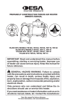
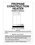
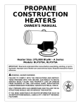
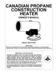
1
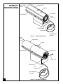
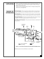
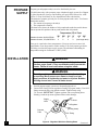
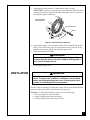
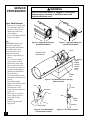
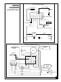
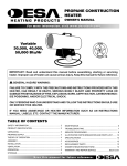
PROPANE
CONSTRUCTION
HEATERS
OWNER’S MANUAL
45 & 80 LP SIDE
150 LP SIDE
PV 0016
PV 017
Heater Sizes: 80,000 150,000 BTU/Hr
IMPORTANT
Read and understand this manual before assembling, starting, or servicing heater. Improper use of heater can cause serious injury. Keep this manual for future reference.
! GENERAL HAZARD WARNING:
FAILURE TO COMPLY WITH THE PRECAUTIONS AND INSTRUCTIONS PROVIDED WITH THIS HEATER, CAN RESULT IN DEATH,
SERIOUS BODILY INJURY AND PROPERTY LOSS OR DAMAGE
FROM HAZARDS OF FIRE, EXPLOSION, BURN, ASPHYXIATION,
CARBON MONOXIDE POISONING, AND/OR ELECTRICAL SHOCK.
ONLY PERSONS WHO CAN UNDERSTAND AND FOLLOW THE INSTRUCTIONS SHOULD USE OR SERVICE THIS HEATER.
IF YOU NEED ASSISTANCE OR HEATER INFORMATION SUCH AS AN
INSTRUCTIONS MANUAL, LABELS, ETC. CONTACT THE MANUFACTURER.
®
CONTENTS
SAFETY
INFORMATION
SECTION
PAGE
Safety Information ......................................................................... 2
Product Identification .................................................................... 4
Unpacking ...................................................................................... 5
Theory of Operation ...................................................................... 5
Propane Supply .............................................................................. 6
Installation ..................................................................................... 6
Ventilation ..................................................................................... 7
Operation ....................................................................................... 8
Storage ........................................................................................... 8
Maintenance .................................................................................. 9
Preventative Maintenance Schedule .............................................. 9
Service Procedures ........................................................................ 10
Specifications ................................................................................ 12
Wiring Diagrams ........................................................................... 13
Accessories .................................................................................... 15
Technical Service .......................................................................... 15
Service Publications ...................................................................... 15
Replacement Parts ......................................................................... 15
Warranty and Repair Service ......................................................... Back Cover
! WARNINGS
! WARNING: FIRE, BURN, INHALATION, AND EXPLOSION
HAZARD. KEEP SOLID COMBUSTIBLES, SUCH AS BUILDING
MATERIALS, PAPER OR CARDBOARD, A SAFE DISTANCE
AWAY FROM THE HEATER AS RECOMMENDED BY THE INSTRUCTIONS. NEVER USE THE HEATER IN SPACES WHICH
DO OR MAY CONTAIN VOLATILE OR AIRBORNE COMBUSTIBLES, OR PRODUCTS SUCH AS GASOLINE, SOLVENTS,
PAINT THINNER, DUST PARTICLES OR UNKNOWN CHEMICALS.
! WARNING
NOT FOR HOME OR RECREATIONAL VEHICLE USE.
The heater is designed and approved for use as a construction heater under ANSI
Z83.7. The primary purpose of construction heaters is to provide temporary heating
of buildings under construction, alteration or repair, and to provide temporary
emergency heat. Properly used, the heater provides safe economical heating.
Products of combustion are vented into the area being heated.
We cannot foresee every use which may be made of our heaters. Check with your
local fire safety authority if you have questions about heater use.
Other standards govern the use of fuel gases and heat producing products for specific
uses. Your local authorities can advise you about these.
Carbon Monoxide Poisoning: Some people are more affected by carbon
monoxide than others. Early signs of carbon monoxide poisoning resemble the flu,
with headaches, dizziness, and/or nausea. If you have these signs, the heater may
not be working properly. Get fresh air at once! Have heater serviced.
2
Safety Information continues on next page
099162
SAFETY
INFORMATION
Continued
! WARNINGS
Propane Gas: Propane gas is odorless. An odor-making agent is added to
propane gas. The odor helps you detect a propane gas leak. However, the odor added
to propane gas can fade. Propane gas may be present even though no odor exists.
Make certain you read and understand all Warnings. Keep this manual for
reference. It is your guide to safe and proper operation of this heater.
• For indoor use only. Provide adequate ventilation.
• Use only in well vented areas. Before using heater, provide at least a threesquare-foot opening of fresh, outside air for each 100,000 BTU/Hr of rating.
This heater produces carbon monoxide, which is listed by the State of California as a reproductive toxin under Proposition 65.
• Do not use heater outdoors or in occupied dwellings.
• Do not use heater in living or sleeping quarters.
• Keep appliance area clear and free from combustible materials, gasoline, paint
thinner, and other flammable vapors and liquids. Do not use heater in areas
with high dust content.
• Keep heater away from strong drafts, water spray, rain, or dripping water.
• Install and use heater with care. Follow all local ordinances and codes. In the
absence of local ordinances and codes, refer to ANSI/NFPA 58. This instructs
on the safe storage and handling of propane gases.
• Check heater for damage before each use. Do not use a damaged heater.
• Use only propane gas set up for vapor withdrawal.
• Keep propane tank(s) below 100° F.
• Do not use heater below ground level. Propane gas is heavier than air. If a leak
occurs, propane gas will sink to the lowest possible level.
• Use only the electrical voltage and frequency specified on model plate.
• The electrical connections and grounding of the heater shall follow the National Electric Code, ANSI/NFPA 70.
• Electrical grounding instructions — This appliance is equipped with a threeprong (grounding) plug for your protection against shock hazard and should be
plugged directly into a properly grounded three-prong receptacle.
• Use only a three-prong, grounded extension cord.
• Use only the hose and factory preset regulator provided with the heater.
• Inspect hose before each use of heater. If highly worn or cut, replace before
using heater. Use the replacement hose assembly specified in this manual.
• Keep heater at least six feet from propane tank(s). Do not point heater at
propane tank(s) within 20 feet.
• Minimum heater clearances from combustibles:
Outlet: 8 Ft.
Sides: 2 Ft.
Top: 6 Ft.
Rear: 2 Ft.
• Locate heater on stable and level surface if heater is hot or running.
• Keep children and animals away from heater.
• Turn off propane supply and unplug heater when not in use.
• When used with thermostat, heater may start anytime.
• Never block air inlet (rear) or air outlet (front) of heater.
• Never move, handle, or service a hot, operating, or plugged-in heater.
• Do not alter heater. Keep heater in its original state.
• Do not use heater if altered.
• Never attach duct work to front or rear of heater.
• Use only original replacement parts. This heater must use design-specific
parts. Do not substitute or use generic parts. Improper replacement parts could
cause serious or fatal injuries.
3
099162
PRODUCT
IDENTIFICATION
Upper Shell
Hot Air Outlet
(Front)
Handle
Fan Guard
Lower Shell
Inlet
Connector
On/Off Switch
Power Cord
Generic LP 45 & 80
LP-PFA/PV 008A
Figure 1 - 80,000 BTU/Hr Model
Hot Air
Outlet
(Front)
Hose /Regulator
Assembly
Upper Shell
Handle
Fan Guard
Lower Shell
Power Cord
On/Off Switch
Generic LP 155
InletLP-PFA/PV 008B
Connector
Hose /Regulator
Assembly
4
Figure 2 - 150,000 BTU/Hr Model
099162
UNPACKING
1. Remove all packing items applied to heater for shipment. Keep plastic cover
caps (attached to inlet connector and hose/regulator assembly) for storage.
2. Remove all items from carton.
3. Check all items for shipping damage. If heater is damaged, promptly inform
dealer where you bought heater.
THEORY OF
OPERATION
The Fuel System: The hose/regulator assembly attaches to the propane gas
supply. The propane gas moves through the solenoid valve and out the nozzle.
The Air System: The motor turns the fan. The fan pushes air into and around
the combustion chamber. This air is heated and provides a stream of clean, hot air.
The Ignition System: The direct spark ignitor (DSI) sends voltage to the spark
plug/ignitor. The spark plug/ignitor ignites the fuel and air mixture.
The Safety Control System: This system causes the heater to shut down if the
flame goes out.
Combustion
Chamber
Fan
Nozzle
Motor
Clean
Heated
Air Out
(Front)
Cool Air In
(Back)
Power
Cord
Spark Plug/Ignitor
DSI
Solenoid
Valve
On/Off Switch
Air For Combustion
And Heating
Hose/Regulator
Assembly
Fuel
Figure 3 - Cross Section
View (80,000 BTU/Hr Model Shown)
45/80Operational
LP SIDE
LP-PFA/OV 001A
Note: Some parts are located differently on some models.
5
099162
PROPANE
SUPPLY
Propane gas and propane tank(s) are to be furnished by the user.
Use this heater only with a propane vapor withdrawal supply system. See Chapter
5 of the Standard for Storage and Handling of Liquefied Petroleum Gas, ANSI/
NFPA 58. Your local library or fire department will have this booklet.
The amount of propane gas ready for use from propane tanks varies. Two factors
decide this amount:
1. The amount of propane gas in tank(s)
2. The temperature of tank(s)
The chart below shows the number of 100 pound tanks needed to run this heater.
Do not operate this product with any tank smaller than 100 pounds.
Temperature (°F) At Tank
-10° -20°
32° 20° 10° 0°
Number of tanks, 80,000 BTU/Hr
Number of tanks, 150,000 BTU/Hr
1
2
1
2
2
3
2
3
3
3
(Use larger tank)
Less gas is vaporized at lower temperatures. You may need two or more 100
pound tanks or one larger tank in colder weather. Your local propane gas dealer
will help you select the proper supply system. The minimum surrounding air
temperature rating for each heater is -20°F (-29°C).
INSTALLATION
! WARNING
Review and understand the warnings in the Safety Information
Section, pages 2 and 3. They are needed to safely operate this
heater. Follow all local codes when using this heater.
! WARNING
Test all gas piping and connections for leaks after installing
or servicing. Never use an open flame to check for a leak.
Apply a mixture of liquid soap and water to all joints. Bubbles
forming show a leak. Correct all leaks at once.
1. Provide propane supply system (see Propane Supply above).
2. Connect POL fitting on hose/regulator assembly to propane tank(s). Turn POL
fitting counterclockwise into threads on tank. Tighten firmly using
7/8" wrench. IMPORTANT: Tighten regulator with vent pointing down.
Pointing vent down protects regulator from weather damage.
Supply
Valve
Hose
Regulator
Propane
Tank
6
Vent
(pointing down)
POL Fitting
Figure 4 - Regulator With Vent Pointing Down
Continued
099162
3. Connect hose to inlet connector. Tighten firmly using a wrench.
IMPORTANT: Extra hose or piping may be used if needed. Install extra hose
or piping between hose/regulator assembly and propane tank. You must use
the regulator supplied with heater.
80,000 BTU/Hr
Model Shown
Inlet Connector
Hose
Figure 5 - Hose and Inlet Connector
Generic LP 45 & 80
LP-PFA/P 023
4. Open propane supply valve on propane tank(s) slowly. Note: If not opened
slowly, excess-flow check valve on propane tank will stop gas flow. If this
happens, close propane supply valve and open again slowly.
5. Check all connections for leaks.
! WARNING
Never use an open flame to check for a leak. Apply a mixture
of liquid soap and water to all joints. Bubbles forming show a
leak. Correct all leaks at once.
6. Close propane supply valve.
VENTILATION
! WARNING
Follow the minimum fresh, outside air ventilation requirements. If proper fresh, outside air ventilation is not provided,
carbon monoxide poisoning can occur. Provide proper fresh,
outside air ventilation before running heater.
Provide a fresh air opening of at least three square feet for each 100,000 BTU/Hr
rating. Provide extra fresh air if more heaters are being used.
Example: A 150,000 BTU/Hr heater requires one of the following:
• a two-car garage door raised six inches
• a single-car garage door raised nine inches
• two thirty-inch windows raised twelve inches
7
099162
OPERATION
! WARNING
Review and understand the warnings in the Safety Information
Section, pages 2 and 3. They are needed to safely operate this
heater. Follow all local codes when using this heater.
To Start Heater
1. Follow all installation, ventilation and safety information.
2. Locate heater on stable and level surface. Make sure strong drafts do not blow
into front or rear of heater.
3. Plug power cord of heater into a three-prong, grounded extension cord.
Extension cord must be at least six feet long. Extension cord must be UL
listed.
Extension Cord Size Requirement
Up to 50 feet long, use 18 AWG rated cord.
51 to 100 feet long, use 16 AWG rated cord.
101 to 200 feet long, use 14 AWG rated cord.
4. Plug extension cord into a 120 volt/60 hertz, three-hole, grounded outlet.
5. Open propane supply valve on propane tank(s) slowly. Note: If not opened
slowly, excess-flow check valve on propane tank will stop gas flow. If this
happens, close propane supply valve and open again slowly.
6. Turn on/off switch to the ON position. Heater will start within twenty seconds.
Note: If heater does not start, turn on/off switch to the OFF position. Wait ten
seconds for safety control to reset, then try again.
To Stop Heater
1.
2.
3.
4.
STORAGE
Tightly close propane supply valve on propane tank(s).
Wait a few seconds. Heater will burn gas left in supply hoses.
Turn on/off switch to the OFF position.
Unplug heater.
! CAUTION
Disconnect heater from propane supply tank(s).
1. Store propane tank(s) in safe manner. See Chapter 5 of Standard for Storage
and Handling of Liquefied Petroleum Gases, ANSI/NFPA 58. Follow all local
codes.
2. Place plastic cover caps over brass fittings on inlet connector and
hose/regulator assembly.
3. Store in dry, clean, and safe place. Do not store hose/regulator assembly inside
heater combustion chamber.
4. When taking heater out of storage, always check inside of heater. Insects and
small animals may place foreign objects in heater. Keep inside of heater free
from combustible and foreign objects.
8
099162
MAINTENANCE
! WARNING
Never service heater while it is plugged in, connected to
propane supply, operating, or hot. Severe burns and
electrical shock can occur.
1. Keep heater clean. Clean heater annually or as needed to remove dust and
debris. If heater is dirty or dusty, clean heater with a damp cloth.
2. Inspect heater before each use. Check connections for leaks. Apply mixture of
liquid soap and water to connections. Bubbles forming show a leak. Correct all
leaks at once.
3. Inspect hose/regulator assembly before each use. If hose is highly worn or cut,
replace.
4. Have heater inspected yearly by a qualified service agency.
5. Keep inside of heater free from combustible and foreign objects.
PREVENTATIVE
MAINTENANCE
SCHEDULE
! WARNING
Never service heater while it is plugged in, connected to
propane supply, operating, or hot. Severe burns and
electrical shock can occur.
Item
How Often
How To
Fan
Clean every 500 hours of
operation or as needed.
See Fan, page 10.
Air Sensing
Switch
(80,000 BTU/Hr
Model Only)
Clean every 500 hours of
operation or as needed.
See Air Sensing
Switch, page 11.
Spark Plug
(80,000 BTU/Hr
Model Only)
Clean and regap every 500
hours of operation or replace
as needed.
See Spark Plug,
page 11.
9
099162
SERVICE
PROCEDURES
! WARNING
Never service heater while it is plugged in, connected to
propane supply, operating, or hot. Severe burns and
electrical shock can occur.
Upper Shell Removal
1. Remove screws along each
side of heater using 5/16"
nut-driver. These screws
attach upper and lower
shells together.
2. Lift or slide upper shell off.
3. Remove fan guard.
Fan
IMPORTANT: Remove fan
from motor shaft before
removing motor from heater.
The weight of the motor
resting on the fan could
damage the fan pitch.
1. Remove upper shell (see
above).
2. Use 1/8" hex wrench to
loosen setscrew which
holds fan to motor shaft.
3. Slip fan off motor shaft.
Be careful not to strike air
sensing switch paddle or
paddle arm (80,000 BTU/
Hr model only).
4. Clean fan using soft cloth
moistened with kerosene or
solvent.
5. Dry fan thoroughly.
6. Replace fan on motor shaft.
Make sure setscrew is
touching back of flat
surface on motor shaft (see
Figure 10).
7. Place setscrew on flat of
shaft. Tighten setscrew
firmly (40-50 inchpounds).
8. Replace fan guard and
upper shell.
Figure 6 - Upper Shell Removal,
80,000 BTU/Hr Model
80,000 BTU/Hr
Model Shown
Figure 7 - Upper Shell Removal,
150,000 BTU/Hr Model
Motor
Fan
Air Sensing
Switch
Paddle
(80,000
BTU/Hr
Model
Only)
Paddle
Arm
Figure 8 - Fan Removal and Air Sensing
Switch Location
45/80 Models
LP-PFA/P 019B
Fan
Fan
Setscrew
Hub
Motor
Shaft
Setscrew
Motor shaft
FAN
LP-PFA/P 023
FAN CROSS SECTION
Figure 9 - Fan, Motor Shaft,
and Setscrew Location
LP-PFA/P 013
Figure 10 - Fan Cross Section
10
099162
Air Sensing Switch
(80,000 BTU/Hr Model)
1. Remove upper shell (see
page 10).
2. Clean air sensing switch
paddle. Use soft cloth
moistened with kerosene
or solvent. IMPORTANT:
Do not scrub. Use gentle
cleaning action. Do not
bend paddle or paddle
arm.
3. Blot paddle dry with a soft
cloth.
4. Replace fan guard and
upper shell.
Air Sensing
Switch
Paddle
Paddle
Arm
Figure 11 - Air Sensing Switch Location, 80,000 BTU/Hr Model Only
150 Model
Ignitor
LP-PFA/P 019A
(150,000 BTU/Hr Model)
1. Make sure gap between
ignitor electrode and
burner nozzle is .13⁄.15".
Access ignitor electrode
from inside combustion
chamber. No other maintenance is needed for
ignitor.
Combustion
Chamber
Spark Plug
(80,000 BTU/Hr Model)
1. Remove upper shell (see
page 10).
2. Remove fan (see page 10).
3. Remove spark plug cable
from spark plug.
4. Place 11/16" socket onto
spark plug mounting nut.
Spark plug mounting nut
is located on spark plug
threads inside combustion
chamber (see Figures 12
and 14).
5. Loosen and remove spark
plug with 13/16" spark
plug socket. Be careful not
to strike air sensing switch
paddle.
6. Clean and regap spark
plug electrodes. Regap
electrodes to .06/.08 inch.
Continued
Spark Plug
Mounting
Nut
Spark Plug
Cable
Spark Plug
Cable
Figure 12 - Spark
Plug and Spark Plug Mounting
Nut Location
Spark Plug Nut Location
LP-PFA/P 021
on Combustion Chamber
Bend Here
To Adjust
Gap
Gap
Figure 13 - Spark Plug Gap
099162
11
7. Replace spark plug into
combustion chamber.
Tighten spark plug mounting nut finger tight onto
spark plug threads. Use
11/16" socket to hold
spark plug mounting nut.
Tighten spark plug to
spark plug mounting nut
using 13/16" spark plug
socket.
8. Attach spark plug cable to
spark plug.
9. Replace fan (see page 10).
10. Replace fan guard and
upper shell.
Spark Plug
Mounting Nut
Combustion
Chamber
Figure 14 - Spark Plug Mounting Nut Location
45/80 Front View
SPECIFICATIONS
Output Rating (BTU/Hr)
Fuel
Fuel Consumption
Gallons/Hour
Pounds/Hour
Supply Pressure To Regulator
Minimum (for purposes
of input adjustment)
Maximum
Regulator Outlet Pressure
(Factory Preset)
Manifold Pressure
Hot Air Output
(CFM Approx)
Motor
Electric Input
Amperage
Ignition
Spark Plug Gap (Inches)
Ignitor Gap (Inches)
Weight (Pounds)
Heater
Shipping
Size - L x W x H (Inches)
LP-PFA/P 018
80,000
150,000
Propane Vapor Only For All Models
0.9
3.7
1.6
7.0
10 psi
10 psi
Tank Pressure For All Models
11" WC
9" WC
12.5" WC
9.8" WC
350
550
3,400 RPM, 1/10 HP
3,430 RPM, 1/8 HP
120 V/60 Hz
120 V/60 Hz
3
2.2
Direct Spark, Interrupted Type For All Models
.06/.08
N/A
N/A
.13/.15
26
30
291/2 x 12 x 181/2
24
35
361/4 x 141/2 x 20
12
099162
Electrical Ladder Diagram
WIRING
DIAGRAMS
Ignition Cable
Flame Sensor
Spark
Plug
Main Valve
Return
Main Valve
Thermostat
Sensor
Neutral
Ground
80,000 BTU/Hr Model
Direct Spark System
Red
Orange
Solenoid
Green/Yellow
Red
White
White
Red
Air Switch
Black
Black
Motor
Switch
On/Off
Green/Yellow
Green
White
Electrical Connection Diagram
Flame Sensor
Red
Red
Air Switch
Spark Plug
Black
Solenoid
Valve
Motor
Green/Yellow
Red
Main Valve
Return
Main Valve
Thermostat
Ground
Neutral
Terminal Board
Sensor
Direct Spark Ignitor
Ignition
Cable
Green/Yellow
White
Orange
White
Black
Black
On/Off
Switch
Black
Green
120 VAC
White
Black
13
099162
WIRING
DIAGRAMS
Electrical Ladder Diagram
Black
150,000 BTU/Hr Model
Green
Thermal
Switch
White
Ignitor
Blue
Blue
Solenoid
Valve
Position of
Leads May
Vary
Orange
Safety
Control
G V VR ACR AC
Green
Blue
Blue
Black
White
Fuse *
Black
Relay S or 2
Black
L or 1
White
Motor
Red
M or 3
Green or
Green/Yellow
Neutral
* If Equipped
Line
Electrical Connection Diagram
Thermal
Switch
Blue
Solenoid
Valve
Blue
Green
Blue
Insulated
Connector
Safety
Control
G
Orange
Ignitor
V VR ACR AC
Position of
Leads May
Vary
Blue
Black
White
Motor
Fuse (If Equipped)
Black
Relay S or 2
Black
Black
On/Off
Switch
Black
Power Cord
120 VAC
Red
L or 1
White
White
M or 3
Green
Green
14
099162
ACCESSORIES
Purchase accessories and parts
from your nearest dealer or
service center. If your dealer
or service center can not
supply an accessory or part,
either contact your nearest
Parts Central (listed in the
separate Authorized Service
Center booklet) or call DESA
International’s Parts Department at (502) 781-9600. You
can also write to the address
listed on the back page of this
manual.
TECHNICAL
SERVICE
SERVICE
PUBLICATIONS
REPLACEMENT
PARTS
Hose: LPA1000 - For 80,000 BTU/Hr Model
A 10 foot hose for locating heater further away from propane tank(s).
Regulator: LPA2080 - For 80,000 BTU/Hr Model
LPA2100 - For 150,000 BTU/Hr Model
Hose and Regulator Assembly: LPA3010 - For 80,000 BTU/Hr Model
LPA3070 - For 150,000 BTU/Hr Model
Fuel Gas Connector: LPA4020 - For All Models
A POL adapter with excess-flow check valve.
Thermostat: HA1210 - For All Models
• Helps economize on fuel
• No installation required
• Plugs into standard 120V outlet
You may have further questions about this heater. If so, contact DESA
International’s Technical Service Department at 1-800-323-5190.
You can receive an Illustrated Parts List free of charge. Send your request and a
self-addressed, stamped envelope to DESA International (address on back page).
Be sure to include the heater model number. You can purchase a service manual
for $5. Make check payable to DESA International.
! WARNING
Use only original replacement parts. This heater must use
design-specific parts. Do not substitute or use generic parts.
Improper replacement parts could cause serious or fatal
injuries. This will also protect your warranty coverage for
parts replaced under warranty.
Parts Under Warranty
Contact authorized dealers of this product. If they can’t supply original replacement
part(s), either contact your nearest Parts Central or call DESA International’s
Technical Service Department at 1-800-323-5190. When calling DESA International,
have ready:
• your name
• your address
• model number of your heater
• how heater was malfunctioning
• purchase date
In most cases, we will ask you to return the defective part to the factory.
Parts Not Under Warranty
Contact authorized dealers of this product. If they can’t supply original replacement part(s), either contact your nearest Parts Central or call DESA International’s
Parts Department at 1-800-972-7879. When calling DESA International, have
ready:
• model number of your heater
• the replacement part number
15
099162
WARRANTY AND REPAIR SERVICE
KEEP THIS WARRANTY
LIMITED WARRANTY
DESA International warrants this product and any parts thereof, to be free from defects in materials and workmanship for
six (6) months from the date of first purchase when operated and maintained in accordance with instructions. This warranty
is extended only to the original retail purchaser, when proof of purchase is provided.
This warranty covers only the cost of parts and labor required to restore the product to proper operating condition.
Transportation and incidental costs associated with warranty repairs are not reimbursable under this warranty.
Warranty service is available only through authorized dealers and service centers.
This warranty does not cover defects resulting from misuse, abuse, negligence, accidents, lack of proper maintenance,
normal wear, alteration, modification, tampering, contaminated fuels, repair using improper parts, or repair by anyone other
than an authorized dealer or service center. Routine maintenance is the responsibility of the owner.
THIS EXPRESS WARRANTY IS GIVEN IN LIEU OF ANY OTHER WARRANTY EITHER EXPRESSED OR
IMPLIED, INCLUDING WARRANTIES OF MERCHANTABILITY AND FITNESS FOR A PARTICULAR PURPOSE.
DESA International assumes no responsibility for indirect, incidental or consequential damages. Some states do not allow
the exclusion or limitation of incidental or consequential damages, or limitations or exclusions may not apply to you. This
Limited Warranty gives you specific legal rights and you may also have other rights which vary from state to state.
We reserve the right to amend these specifications at any time without notice. The only warranty applicable is our
standard written warranty. We make no other warranty, expressed or implied.
WARRANTY SERVICE
Should your heater require service, return it to your nearest authorized service center. Proof of purchase must be presented with the heater. The heater will be inspected. A defect may be caused by faulty materials or workmanship. If so,
DESA International will repair or replace the heater without charge.
REPAIR SERVICE
Return your heater to your nearest authorized service center. Repairs not covered by the warranty will be billed at
standard prices. Each Service Center is independently owned and operated. We reserve the right to amend these specifications at any time without notice.
Model
Serial No.
Date of Purchase
2701 Industrial Drive
P.O. Box 90004
Bowling Green, KY 42102-9004
For information, write: DESA International, P.O. Box 90004
Bowling Green, Kentucky 42102-9004 ATTN: Customer Service Department
When writing, always include model number and serial number.
099162-01
Rev. F
10/94