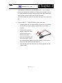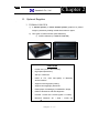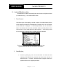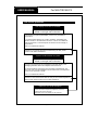
1
*Hanatech reserves the right to change, modify
the content of this instruction manual for product
enhancement both technical and non technical
without notice.
This may include scan tool graphic displays,
vehicle coverage, supported functions both
technical, non technical and operating procedures.
Hardware may also be modified, altered or
redesigned or may differ from the descriptions
and illustrations displayed in this manual
CHAPTER 1
SAFETY AND WARRANTY
I. SAFETY INSTRUCTIONS
………….
1-2
II. SAFETY PRECAUTIONS
………….
1-4
III. WARRANTY SERVICE
………….
1-6
………….
1-8
FCC RF INTERFERENCE STATEMENT
Hanatech Co., Ltd.
Chapter 1
Safety and Warranty
About this Manual
All rights reserved by Hanatech Co., Ltd., Gumi, Korea.
The contents of this manual are the result of contributions by dozens
of individuals all who have added their vital expertise and experience to
the evolution of the contents of this manual.
The information contained in this manual may contain printing errors
and is subject to change without notice according to product upgrade.
Hanatech shall not be liable for errors contained herein or for incidental
or consequential damage in connection with the furnishing, performance,
or use of this material.
No part of this manual may be photocopied, reproduced, or translated
to another language in any way without the prior written consent of
Hanatech Co., Ltd.
Using this Manual
It is recommended that the user become familiar with the
operating procedures, terminologies and information contained
within this user’s manual. This will help to increase the user’s
effectiveness with this equipment.
Vehicle system familiarity
While this equipment provides very powerful functions with extensive
vehicle coverage, it cannot replace knowledge and skill. To get the
most out of this equipment, a full understanding of vehicle systems is
required. It is recommended that the equipment be used in conjunction
with the original service manual for the vehicle being tested.
The equipment is designed for use by trained service personnel and
this manual assumes that the service technician who is going to use this
equipment has a familiarity with vehicle electronic control systems,
however, the latest service manuals and bulletins should always be
referenced before using this equipment.
Chapter 1 - 1
USER MANUAL
For MULTISCAN P2
I. SAFETY INSTRUCITONS ----------------------Thank you for purchasing MULTISCAN P2. To get the maximum performance of
the equipment, please carefully read this manual first, and keep it at hand.
On delivery inspection
When the equipment is delivered, a check should be made for any damaged or
missing components. If the unit is damaged or fails to operate according to the
specifications, contact your local distributor or the manufacturer, Hanatech Co., Ltd.,
Hana bldg., 1032-39 Wonpyeong-dong, Gumi-shi, Kyung-buk Republic of Korea 730924. In the unlikely event the equipment requires shipping back to the manufacturer,
please use the original packing material.
Safety symbols
The following symbols are used throughout this manual:
DANGER
This mark means that dangerous consequences may
arise, with the possibility of death or serious injury to the
user, if the machine is handled incorrectly.
WARNING
This mark means dangerous consequences may arise,
with the possibility of somewhat serious injury to the user
and or damage to the machine and facilities, if the
equipment is handheld incorrectly.
SYMBOL
Description
This symbol is affixed to locations on the equipment where
the operator should consult corresponding topics in this
manual (which are also marked with the
symbol) before
using relevant functions of the equipment. In the manual,
this symbol indicates explanations that are particularly
important that the user is expected to read the manual before
using the equipment.
This symbol represents DC (Direct Current)
Chapter 1 - 2
Hanatech Co., Ltd.
Chapter 1
Safety guideline
In order to ensure proper operation and satisfactory performance, observe the
cautions listed below.
DANGER
This equipment is designed to comply with IEC61010-1 safety standards, and
has been tested for safety prior to shipment. Excessive high voltage measurement
or improper operation could result in personal injury, as well as damage to the
equipment or the vehicle. Please read this manual carefully and be sure that you
understand its contents before using the equipment.
The manufacturer disclaims all responsibility for any accident except for that
resulting due to defect in its product.
WARNING
For safety reasons, this equipment should not be used to
measure circuits carrying more than 30Vrms or 42.4V peak.
To avoid electrical accident that could result in injury or
death, do not measure voltage in excess of these limitations.
Maximum rated measurable voltage is 30Vrms or 42.4V
peak.
Chapter 1 - 3
USER MANUAL
For MULTISCAN P2
II. SAFETY PRECAUTIONS ----------------------DANGER
When an engine is running, keep the workshop area WELL
VENTILATED or attach a building exhaust removal system to the
engine exhaust system. Engines produce carbon monoxide, an
odorless and poisonous gas that causes slower reaction time
and may lead to serious injury or death.
WARNING
Brakes and wheel blocks
Apply the hand brake and block the wheels before using the test
equipment. It is highly recommended to block the wheels on
front-wheel drive vehicles because the hand brake does not hold
the driving wheels.
Drive Test
Do not drive the vehicle and operate the test equipment at the
same time. Any distraction may cause an accident. Have one
person operate the test equipment while the other person drives
the vehicle.
Never place the test equipment in front of you when driving the vehicle because the
test equipment may hit your body and cause serious injury when
the air bag inflates.
Do not try to test the SRS air bag system while driving the
vehicle as unintended air bag inflation may result.
Chapter 1 - 4
Hanatech Co., Ltd.
Chapter 1
Engine Compartment
Maintain sufficient clearance between moving components or
belts while using the test equipment in the engine compartment.
Moving components and belts may catch loose clothing, test
cables or a part of your body and cause damage or personal
injury.
Electrical Components
Always turn the ignition key OFF when connecting or disconnecting electrical
components unless otherwise instructed.
Vehicle Battery
MULTISCAN P2 is designed to prevent damage from reverse polarity battery cable
connection, however, it is always highly recommended to always ensure correct
polarity terminal connection.
Never lay the test equipment on vehicle battery. You may short the terminals and may
cause damage to your body, the test equipment or the battery.
To avoid damaging the test equipment or displaying false data, make sure the vehicle
battery is fully charged and the connections to the electronic control module are clean
and tight.
The warning messages above and the safety messages contained hereinafter cover
situations Hanatech is aware of. Hanatech cannot know, evaluate or advise you as to
all of the possible hazards.
You must make sure that any conditions or service
procedures encountered do not jeopardize your personal safety.
Chapter 1 - 5
USER MANUAL
For MULTISCAN P2
III. WARRANTY SERVICE ------------------------Warranty Period
In principle, MULTISCAN P2 is warranted to the customer to be free of defects in
material and workmanship for the period of 1 year and 3 years for main board after the
date of registration.
When the product is found defective during this period, the product can be returned to
Hanatech and will be repaired or replaced free of charge.
Freight and Repair Cost
During the warranty period, the repair cost and freight cost are covered by
manufacturer. When the defective product or part needs to be sent to the
manufacturer, it should be advised by the local distributor about how to send and the
validity of remaining warranty period before sending the defective material.
Upon delivery
Hanatech inspects all the ordered product parts and components are included in the
package before shipment, and include the original copy of pre-shipment inspection
report in the box. As soon as the product is delivered to you, please ensure
everything you ordered is properly checked and included referring to the pre-shipment
inspection report. If there is anything missing or damaged, you must notify the local
distributor immediately within 3 working days from the delivery date for free of charge
replacement of the parts.
In case of trouble
If you encounter any malfunction or trouble with the equipment, please refer to the
Trouble Shooting chapter in this manual. If the problem cannot be solved, please
contact your local distributor for assistance. For early identification of a fault or error,
your local distributor will require the following details:
1. Symptom of problem you are experiencing
2. Serial number of the head unit
Chapter 1 - 6
Hanatech Co., Ltd.
Chapter 1
3. Vehicle information: Which specific car were you testing when the problem
occurred – Model name, Model year and system ID number if available (for Mitsubishi,
Subaru and Suzuki only: Refer to Japanese car chapter for details)
Warranty Void
Even in the effective warranty period, if the problem is found to be caused by any of
the followings, Hanatech charges the cost for round trip freight and actual cost for the
service to the customer, and the shipment back to the customer will be suspended
until the customer’s payment is duly made
1. Evidence of improper use or application of the product ignoring the cautions and
warnings stipulated in the user’s manual
2. Intentional damages or modifications to the product or user’s attempt to repair
without proper authorization
3. Any damage caused by Force Majeure including war and natural disaster
4. Loss of time, inconvenience and other consequential damage or loss
Warranty void seal
In addition to the above mentioned warranty void conditions, warranty service is not
provided in case the warranty void seal is broken or removed.
If you remove the head unit safety boot, you will see a yellow round sticker covering
one of the screw holes in the back. Please be careful not to break this seal and never
try to open the head unit without direct authorization from the manufacturer.
Bought in other countries
Only the products properly supplied by the contracted authorized local distributors are
recognizable for free of charge warranty service. Any equipment bought outside the
contracted national territory of your local distributor will be charged for service.
Chapter 1 - 7
USER MANUAL
For MULTISCAN P2
FCC RF INTERFERENCE STATEMENT
Note
This equipment has been tested and found to comply with the limits for a Class B
digital device, pursuant to Part 15 of the FCC Rules.
These limits are designed to provide reasonable protection against harmful
interference in a residential installation.
The equipment generates, uses and can radiate radio frequency energy and, if not
installed and used in accordance with the instructions, may cause harmful interference
to radio communications. However, there is no guarantee that interference will not
occur in a particular installation.
If this equipment does not cause harmful interference to radio or television reception
which can be determined by turning the equipment off and on, the user is encouraged
to try to correct the interference by one or more of the following measures;
-
Reorient or relocate the receiving antenna
-
Increase the separation between the equipment and receiver
-
Connect the equipment into an outlet on a circuit different from that to which the
receiver is connected
Caution
Changes or modification not expressly approved by the party responsible for
compliance could void the user’s authority to operate the equipment.
THIS DEVICE COMPLIES WITH PART 15 OF THE FCC RULES. OPERATION IS
SUBJECT TO THE FOLLOWING TWO CONDITIONS; (1) THIS DEVICE MAY NOT
CAUSE HARMFUL INTERFERENCE. AND (2) THIS DEVICE MUST ACCEPT ANY
INTERFERENCE RECEIVED INCLUDING INTERFERENCE THAT MAY CAUSE
UNDESIRED OPERATION.
Chapter 1 - 8
CHAPTER 2
SPECIFICATION AND PARTS
I. SPECIFICATION
………….
2–1
II. PART LIST
………….
2–3
A. Head unit and basic supplies
2-3
B. Diagnostic Adapters
2-6
C. Software Cartridge
2 - 15
D. Spare Parts
2 - 16
E. Optional Supplies
2 - 17
Hanatech Co., Ltd.
Chapter 2
Specification and Parts
I.
Specification ----------------------------------A. Hardware
CPU: 16bit, 33MHz
RAM: 1 M byte (SRAM)
Program Cartridge Memory: 512MBytes Flash Memory
Display: 320×240 Monochrome Graphic LCD with Back Light
Key Pad: 20 membrane keys, embossing type
Communication Port: USB and RS232
Printer: General PC printer
Power: DC 12V, 700mA
SUPER CAP (2.7V / 10F SERIAL 5EA)
- Maintain the system without power for about 10 seconds when fully charged
B. Environmental Specification
Indoor use only
Operating temperature: Max 50℃ / 122℉
Maximum relative humidity: 80% (up to 31℃/88℉) and 50% (40℃/104℉ or
higher)
Installation overvoltage categories: CATⅡ
Maximum measurable voltage: DC 30V Max
Pollution degree 2
Max. Altitude: Up to 2000m
Chapter 2 - 1
USER MANUAL
For MULTISCAN P2
C. Mechanical Dimensions
Length: 222㎜ / 9"
Width: 187㎜ / 7.5"
Height: 51㎜ / 2"
Weight: 950g / 2.1lb (head unit only)
Body Color: Dark Grey
Safety Boot Color: Blue
All specifications are subject to change without notice for the purpose of product
and quality improvement.
Chapter 2 - 2
Chapter 2
Hanatech Co., Ltd.
II. Part List ----------------------------------------A. Head unit and basic supplies
1. Head Unit (P/N. 1000-0007)
1) Made of strong ABS resin, each unit has
passed
internal
impact
test
before
shipment.
2) As the inner surface is coated with antielectromagnetic interference material, it
neither interferes the other electronic
devices nor gets interfered by the other
equipments.
2. Safety Boot (P/N. 2003-0032)
1) Flexible plastic cover that protects the head unit from physical,
chemical and electrical damage
2) Basic color is blue, however, it can be changed according to the
distributor’s demand.
Chapter 2 - 3
USER MANUAL
For MULTISCAN P2
3. Carry Case (P/N. 3003-0003)
Provides convenient transportation and the
protection
of
the
head
unit
and
other
components from outer physical impact during
the transportation and storage. Carry case is
provided when purchasing the head unit and at
least one software package together. Includes
keys and dial lock
4. Main Data Link Cable (P/N. 3001-0001)
- Connects vehicle side DLC and MULTISCAN
P2 head unit for data
transmission.
-
Connecting parts on both ends
are
exactly
same,
therefore,
simply put any one end to the
head unit, and then hook the
other end to the vehicle side
DLC
after
connecting
an
appropriate adaptor
5. Power Cable 1 – Cigarette Lighter (P/N. 3000-0004)
-
Supplies power to the head unit
from the cigarette lighter socket.
Used when DLC is located near
the driver or passenger seat and
power is not supplied through
DLC.
-
LED lights on both ends turn ON
when power is properly supplied.
-
The metal plunger part in the end of cigarette lighter connector is
Chapter 2 - 4
Hanatech Co., Ltd.
Chapter 2
removable by unscrewing for the fuse replacement. It may become
loose over repeated use, therefore, it is highly recommended to check if
it is tightly screwed frequently. A set of plunger parts are included in the
basic supplies. Refer to spare parts section hereinafter.
-
The rated voltage and current for this power cable are 12V and less than
2A.
6. Power cable 2 – Vehicle Battery (P/N. 3000-0005)
-
Supplies power from the vehicle battery when the DLC is located in
the engine bay or when using the oscilloscope or multi-meter
functions
-
Connect each of the two
alligator clips to the battery
terminal of the correct
polarity with caution.
-
Must be used together with
the Power Cable 1. Insert
the cigarette lighter adaptor of the Power Cable 1 into the socket,
and connect the other end to the head unit.
-
Red LED light turns ON when power is properly supplied from the
vehicle battery.
Chapter 2 - 5
USER MANUAL
For MULTISCAN P2
B. Diagnostic Adapters
Diagnostic adapters may be sold separately, therefore check if all the
adapters you ordered are included in the package upon delivery.
There are two types of adapters: capsulated and wired types.
Most of MULTISCAN P2 adapters are capsulated for better durability and
storage, however, sometimes it is difficult or almost impossible to connect the
capsulated adapter to vehicle side DLC when it is located deep inside
beneath the dashboard. We use wire type adapters for the cars such as
Hyundai and Kia that we were reported to have such connecting difficulties.
Capsule type
1. OBD2 Standard Adapter
(P/N. 3001-0010)
Used for all OBD generation 2 and EOBD
compatible vehicles.
Vehicle side DLC is
generally located near the driver’s seat and
most frequently found beneath the dash panel.
2. Toyota / Lexus 17Pin Rectangular
Adapter (P/N. 3001-0011)
Used for the diagnosis of Toyota and Lexus
of OBD generation 1. Vehicle side DLC of
this type is generally located in the engine
compartment.
Chapter 2 - 6
Wire type
Chapter 2
Hanatech Co., Ltd.
3. Toyota/Lexus 17Pin Semi-circular Adapter (P/N. 3001-0012)
Also used for the diagnosis of Toyota and
Lexus of OBD generation 1.
The vehicle side DLC is generally found
beneath the dashboard.
Refer to the following warning message.
WARNING
The appearances of this adapter and MAZDA 17Pin adapter are exactly
same, however, the internal wiring and circuit are different. Check the
engraved name and the body color of the adapter carefully before use.
Improper adapter connection may result in serious malfunction of
either control system and MULTISCAN P2 head unit.
4. Honda 3 Pin Adapter and 2 Pin Jump Wire
(P/N. 3-pin: 3001-0014, 2-pin wire: 3001-0023)
3-pin adapter is used for the diagnosis of Honda
cars of OBD generation 1 that support DTC
read and erase as well as data stream.
Older Honda cars have 2-pin DLC that supports
DTC read only. The jump wire is used for these
older cars to bridge the 2-pin DLC terminals.
The vehicle side DLC is generally located under
the dashboard or the glove box.
Chapter 2 - 7
USER MANUAL
For MULTISCAN P2
5. Mitsubishi and Hyundai 12Pin Adapter (P/N. 3001-0001)
Used for the communication
with Mitsubishi and Hyundai
cars of OBD generation 1.
A wire type adapter is provided
as the connecting difficulties of
capsule type adapter in quite a
few
Hyundai
cars
were
reported.
6. Mitsubishi 12+16pin dual headed adapter (P/N: 3001-0030)
Used for the communication with
Mitsubishi cars with both of 12-pin
OBD1 and 16-pin OBD2 adapters
on-board.
Refer to the Mitsubishi section,
Chapter 6 for details.
7. Nissan and Samsung 14Pin Adapter (P/N. 3001-0006)
Used for the communication with Nissan cars
of OBD generation 1 and all Samsung
passenger cars.
Vehicle side DLC is generally found under the
dash or inside the fuse box.
8. Mazda 17Pin Adapter (P/N. 3001-0013)
Used for the communication with Mazda cars
of OBD generation 1.
Vehicle side DLC is generally located in the
engine compartment.
Refer to the warning message in the next page:
Chapter 2 - 8
Hanatech Co., Ltd.
Chapter 2
WARNING
The appearances of this adapter and Toyota 17Pin SEMI-CIRCULAR adapter
are exactly same, however, the internal wiring and circuit are different. Check
the engraved name and the body color of the adapter carefully before use.
Improper adapter connection may result in serious malfunction of either
control system and MULTISCAN P2 head unit
9. Subaru 9Pin Adapter (P/N. 3001-0022)
Used for the communication with Subaru cars of
OBD generation 1.
The vehicle side DLC is generally located
beneath the dashboard.
10. GM Daewoo 12Pin Adapter
(P/N. 3001-1002)
Used for the communication with Daewoo cars
of OBD generation 1.
The vehicle side DLC is generally located
beneath the glove box, door side.
11. Kia 6Pin Adapter (P/N. 3001-0003)
Used for the communication with old
Kia cars of OBD generation 1.
Only the Diagnostic Trouble Code
reading function is available for the
cars with this type of adapter as only
the slow pulse signal is transmitted
through the vehicle side DLC.
The split wire of the adapter is to be connected to the ground terminal of
the vehicle side DLC.
Chapter 2 - 9
USER MANUAL
For MULTISCAN P2
12. Kia 20Pin Adapter (P/N. 3001-0004)
Used for the communication with Kia cars of OBD generation 1.
DTC read & erase and data stream
functions are available for the cars
with this type of adapter.
Refer
to
the
following
warning
message.
WARNING
The appearances of Kia 20Pin adapter and Ssangyong 20Pin Rectangular
adapter are exactly same, however, the internal wiring and circuit are different.
Check the engraved name and the body color of the adapter carefully before
use. Improper adapter connection may result in serious malfunction of
either control system and MULTISCAN P2 head unit
13. Ssangyong 20Pin Rectangular Adapter (P/N. 3001-0005)
Used for Ssangyong cars of OBD
generation 1.
Vehicle side DLC is located in the
engine compartment.
Refer to the warning above.
14. Ssangyong 14Pin Circular Adapter
(P/N. 3001-0007)
Used
for
old
Ssangyong
cars
of OBD
generation 1.
Vehicle side DLC is located in the engine
compartment.
Chapter 2 - 10
Hanatech Co., Ltd.
Chapter 2
15. Holden 6 Pin Adapter (P/N. 3001-0023)
Used for Australian Holden of OBD
generation 1.
Japanese cars such as Toyota and Nissan
assembled in Australia with Holden built
engines may have this type of adapter, too.
Vehicle side DLC is generally located
beneath the glove box to the center facia.
16. GM Opel 10Pin Adapter (P/N. 3001-0019)
Used for the communication with
Opel cars of OBD generation 1.
Also available with MULTISCAN P2
Australian Holden, South American
Opel
and
European
Vauxhall
software packages.
Vehicle
side
DLC
is
generally
located in the fuse box beneath the dashboard or near the parking brake.
17. Ford 20 Pin Adapter (P/N. 3001-0020)
Used for the communication with Ford cars of
OBD generation 1, including Australian and
British Fords.
Vehicle side DLC is generally located in the
fuse box beneath the dashboard.
Chapter 2 - 11
USER MANUAL
For MULTISCAN P2
18. Ford EEC-IV (P/N. 3001-0017)
Used
for
the
communication
with
Australian Ford cars of OBD generation 1,
Vehicle side DLC is generally located in
the engine compartment.
19. BMW 20Pin Adapter (P/N. 3001-0016)
Used for the communication with
BMW cars.
Vehicle
side
DLC
is
generally
located beneath the dashboard or in
the engine compartment.
20. VAG 2X2Pin Adapter (P/N. 3001-0029)
Used for the communication with
Volkswagen/Audi Group cars,
Vehicle side DLC is located in
various place on the vehicle but
generally around dashboard.
Applied with SEAT, SKODA with
this adapter also.
Chapter 2 - 12
Chapter 2
Hanatech Co., Ltd.
21. Mercedes Benz 38Pin Adapter (P/N. 3001-0015)
Used
for
the
communication
with
Mercedes Benz cars equipped with 38Pin
vehicle side DLC.
Applied with C202, CLK208, E210, E124,
S140, SL129, SLK170, G463, G461.
22. Mercedes Benz 4Pin Adapter (P/N. 3001-0009)
Used for the communication with Mercedes Benz cars equipped with
8Pole or 16Pole vehicle side DLC.
(Red: Battery +, Gray: K Line,, Yellow :
Ignition check, Black: Ground)
Applied with C201, E124, S126, SL107,
G463
23. Upgrade cable (P/N. 3000-0010)
To be connected to main data link
cable
for
MULTISCAN
updating
P2
software
your
by
downloading updated codes from
your PC. Refer to the related
chapter in this manual.
Chapter 2 - 13
USER MANUAL
For MULTISCAN P2
24. Internal ULTRAPLEXER (P/N. 3001-0032)
Chrysler 12+16Pin cable 15Pin D Sub (to Main Cable => Scanner) to
12+16Pin adaptor (to Sebring/Stratus vehicle side adaptor)
25. Fiat 3Pin (P/N. 3001-0031)
Used for the communication with
OBD1 generation cars of Fiat
the
Group.
Vehicles side DLC is located in various
place on the vehicle but generally around
dashboard.
(Can be supplied as an optional part)
26. DC POWER CABLE (P/N. 3001-
Chapter 2 - 14
)
Chapter 2
Hanatech Co., Ltd.
C. Software Cartridge
1) Contains
vehicle
information
and
operating
software
for
ULTRASCAN P1 scanners.
2) The appearance and measurements for ULTRASCAN P1 cartridges
complies with standard PCMCIA, however, inner circuits are of
Hanatech’s own design. Therefore, you can neither use it with the
other equipment nor copy its contents to the other standard PCMCIA.
WARNING
MAKE SURE TO TURN POWER OFF BEFORE REMOVING OR INSERTING
A CARTRIDGE. It is extremely dangerous to insert or remove a PCMCIA card
while the head unit is turned on. Both PCMCIA card and head unit can be
critically damaged and broken down. Always turn power off by pressing the
[POWER] key or removing power supply cable from the head unit before
inserting or removing a PCMCIA card..
Chapter 2 - 15
USER MANUAL
For MULTISCAN P2
D. Spare Parts
1) Extra fuses (P/N. 3008-0003)
For the replacement of the fuse located inside the
cigarette lighter power cable. You can also replace
it with a fuse of which rated current is 2 Ampere or
less.
2) Spare cigarette lighter power cable plunger parts
A set of spare parts for replacement when
the original parts are lost.
-
Host-Pro PC Interface software CD.
Consisted of a software installation CD (P/N. 3005-0002), 5 meter
USB cable (P/N. 3000-0014).
Enables realtime PC interface of MULTISCAN P2 scanners. Refer
to the PC interface section of this manual and the separate HOSTPRO user manual for further information.
* Host Pro PC Interface software CD will be released later as of the
date Feb 15. USB cable is generally easy to get and Kit may not
include it without any notice
Chapter 2 - 16
Hanatech Co., Ltd.
Chapter 2
E. Optional Supplies
.
1. THERMAL PRINTER
1) A thermal printer (or direct thermal printer) produces a printed
image by selectively heating coated thermochromic paper.
2) Two types of Thermal Printer (Size difference)
1) PORTI-SW40/45 (3’’ MOBILE PRINTER)
FEATURES
•
Pocket size (107.5 x 88.5 x 45mm)
•
High speed (60mm/sec)
•
203 dpi : 8 dots/mm
•
UART or TTL, IrDA Ver1.0(SIR) or Bluetootn
Ver2.0 interface
•
Support text and graphic printing.
•
Support bit-image(logo) download.
•
Easier paper roll loading by CLAMSHELL design.
•
Easier maintenance with self-diagnostic.
•
Free fall: 1 meter onto concrete (option 1.5 meter)
•
Microsoft Windows XP / 2000 / VISTA OS
ibl
Chapter 2 - 17
USER MANUAL
For MULTISCAN P2
2) PORTI-SC30 (2’’ MOBILE PRINTER)
FEATURES
•
Pocket size (75.5 x 112 x 34mm)
•
Light weight(224g) for true mobility
•
Very silent printing thru direct thermal printing
method
•
High speed (80mm/sec, MAX)
•
High resolution (203dpi:8dots/mm)
•
UART or TTL, Bluetooth Ver2.0 interface
•
IrDA
Ver1.0(SIR)(optional),
USB(optional)
interface
•
Support text and grahpic printing
•
MSR : ISO/IEC 7810, ISO/IEC 7811 (1/2 Track or
2/3 Track)
•
Support bit-image(logo) download
•
Easier paper rollloading by CLAMSHELL design
•
Easier maintenance with self-diagnostics
•
Using Combined with CDMA phone or PDA
•
Free fall: 1 meter onto concrete (option 1.5 meter)
•
Microsoft Windows ME / XP / 2000 / VISTA OS
compatible
Chapter 2 - 18
CHAPTER 3
OPERATING MULTISCAN P2
GETTING STARTED
I.
………….
3–1
A. Head unit
3–1
B. Main DLC Cable
3–2
C. Power Supply
3–3
D. Contrast
3–5
CONTROL KEYS
………….
3–6
A. Key pad
3–6
B. Making Selection in the menu
3–6
C. Function keys
3–7
II. CONFIGURATION
A. Software Information
B. Special Functions
………….
3–9
3–9
3 – 10
Hanatech Co., Ltd.
Chapter 3
Operating MULTISCAN P2
Getting Started--------------------------------A. Head Unit
①. LCD Display
②. Key Pad (may be designed differently)
③. 12V Power Jack Connection
④. 15-pin Main DLC Cable Connection
⑤. USB port
⑥. RS232 Serial Communication Port
⑦. LCD Contrast Adjustment Dial
⑧. PCMCIA slot
Chapter 3 - 1
USER MANUAL
For MULTISCAN P2
B. Main DLC Cable
1. Connection to the head unit
a. The male connectors in both ends of the main DLC cable are exactly
same and you can connect any of them to the head unit.
b. Press the main DLC cable connector into the head unit 15 pin female
connector, and tighten up the two screws for firm connection.
2. Connecting the DLC adapters
Locate the vehicle side adapter and connect the corresponding DLC adapter
to the remaining male connector of the main DLC cable
CAUTION
It is recommended to keep the main DLC cable connected and screwed
to the head unit. Frequent connection and removal of the main DLC
cable may loose the fastening parts and bend the connecting pins.
Chapter 3 - 2
Hanatech Co., Ltd.
Chapter 3
C. Power supply
1. Power supplied through DLC adapter
12V battery power is supplied through most of the DLC adapters except
GM/Daewoo 10Pin and Mitsubishi/Hyundai 12Pin adapters
2. Cigarette lighter
a. Use the cigarette lighter cable when power is not supplied through the
DLC adapter.
b. Insert the cigarette lighter connector into the socket, and check if the red
LEDs in both ends of the cable are ON.
c.
Insert the power jack into the head unit power socket.
Chapter 3 - 3
USER MANUAL
For MULTISCAN P2
3. Vehicle battery
a. Sometimes it is necessary to put the head unit in the engine
compartment when testing OBD1 generation vehicles with the
diagnostic adapters located near the engine, such as Toyota, Mazda,
Kia, Ssangyong, BMW, Mercedes Benz, etc.
b. In case power is not supplied through the diagnostic adapter,
connect the alligator clips of the battery power cable to the battery
terminals of correct polarity.
Check the red LED on the round
socket turns ON.
c.
Connect the cigarette lighter power cable connector into the battery
power cable socket.
4. Power ON
MULTISCAN P2 automatically turns on when power is supplied properly..
Chapter 3 - 4
Hanatech Co., Ltd.
Chapter 3
D. Contrast
a. The LCD display is sensitive to the temperature.
It may become too faint when it is cold and too dark when it is hot.
b. If the screen is too faint or too dark to read, you can adjust the contrast by
turning the contrast dial in the right side of the head unit.
c.
In case of any trouble with the display, please refer to the Trouble Shooting
chapter in this manual.
Chapter 3 - 5
USER MANUAL
I.
For MULTISCAN P2
Control Keys -----------------------------------
A. Keypad
The keypad is made of chemistry proofing PVC
material that prevents contamination and damage
from hazardous oily workshop environment.
The membrane keypad is designed and tested to
maintain
its
normal
operation
over
a
million
keystroke for each.
Each key is raised for better tactile feel. The keypad
has total of 20 keys.
B. Making selection in the menu
1. Numeric Keypad in the bottom
Simply press the corresponding number when making selection from a menu.
This is available only when you are selecting an item of which number is 9 or
less. For more than 10, you should locate the highlighted bar on the desired
item and press the [ENTER] key.
2. Arrow keys in the middle
◀ ▶
Page Up/Down
▲▼
Scroll Up/ Down
Chapter 3 - 6
Hanatech Co., Ltd.
Chapter 3
a. Scroll up and down the highlighted bar in the menu by pressing Up/Down
arrow keys and press the [ENTER] key to confirm the selection.
b. If the menu has more than 12 items, you may have to move between the
pages to make selection. You do not have to pound on Up/Down arrow
keys to scroll the whole page. Simply pressing the Left or Right arrow
key will shift page to page. Move the highlighted bar by pressing the
up/down keys when the desired item appears on the screen, and press
the [ENTER] key.
c.
If differently defined, key instructions will be given in the bottom of the
screen.
C. Function keys
1. ESC
Used to abort an operation of MULTISCAN P2 or to return to the upper level
menu.
If differently defined, key instructions will be given in the bottom of the screen.
2. HELP
a.
DTC Read
-
When a trouble code is detected, you can press this key to view the
detailed information of the DTC.
-
DTC definition, DTC registration conditions and check points are
provided (For Korean and Malaysian cars only.)
Chapter 3 - 7
USER MANUAL
b.
For MULTISCAN P2
Service Data (Live Data Stream)
-
While live data is being displayed on the screen, select a live data
item by moving the highlighted bar, and press this key to view the
detailed information about the selected item.
-
Standard value and technical explanations are provided. (For
Korean and Malaysian cars only.)
3. ERASE
When one or more DTC(s) are found, you can press this button to erase the
DTC. A query to confirm your intention to erase the DTC will follow.
4. ENTER
a. To confirm the selection after locating the highlight bar on a desired item
in the menu.
b. To proceed to the next step when the instruction or pop-up message
appears.
c.
To freeze the live data parameter in the top of the screen. Refer to the
freeze data function in the following chapter.
d. If differently defined, key instructions will be given in the bottom of the
screen.
Chapter 3 - 8
Hanatech Co., Ltd.
Chapter 3
II. Configuration ---------------------------------Press the [4] key from the initial function menu to proceed to the configuration
menu. You can check the version numbers of the software packages contained
in the 512MB memory card, test the keypad and LCD, set up sound and language
options and download software updates in the configuration menu.
A. Software Information
When you select [1. SOFTWARE INFORMATION] in the configuration menu, a
list of software packages contained in the 512MB memory card will appear as
below:
Should you get any update files from your local distributor or from Hanatech
website, please compare the version number and last update date to check if the
update is necessary.
Chapter 3 - 9
USER MANUAL
For MULTISCAN P2
B. Special functions
1. Download software
-
You can download the software updates from your PC when you
select [1. DOWNLOAD SOFTWARE].
-
Instructions will be given separately whenever an update is available.
Contact your local distributor for the availability of update frequently
and keep posted of such events.
2. Language
-
You can select provided language. English and Spanish languages
are available for menu selection.
3. Sound
-
You can toggle ON and OFF the key sound.
4. Save Configuration
-
If you have made any change in this [Special Function] menu, you
have to save the configuration to make such changes effective.
-
Press the [4] key to save the changes in configuration
Chapter 3 - 10
CHAPTER 4
I.
FUNCTIONS
DIAGNOSTIC TROUBLE CODE
………….
4–1
A. DTC Read
4–1
B. DTC Erase
4–4
C. DTC Help Tips
4–5
II. CURRENT DATA
………….
4–6
A. Pulse Signal Type
4–6
B. Serial Communication Type
4–6
C. Data Freeze
4–7
D. Data Graph
4–8
E. Help Tips
4 – 10
III. ACTUATION TEST
………….
4 – 11
IV. BLACK BOX
………….
4 – 14
V. CONNECTOR LOCATION
………….
4 – 27
VI. IMMOBILIZER
4 – 29
Hanatech Co., Ltd.
Chapter 4
MULTISCAN P2 Functions
The functions you can choose when all the test vehicle details are selected
properly are explained in this chapter of the manual.
The actual list of
available functions may be different according to the vehicle you want to test.
I.
Diagnostic Trouble Code---------------------
A. DTC Read
1. Pulse signal type
a. Many of old Toyota, Honda, Mazda, Hyundai and Kia cars until early 90’s
support slow pulse signal output for the DTC reading function.
As shown below, MULTISCAN P2 shows the pulse signal being received
through the DLC adapter in the top and the received DTC numbers.
b. Manual input
-
Even older cars such as Honda with 2-pin adapter have no signal
output terminal for DTC in the DLC adapter.
In this case,
MULTISCAN P2 shows the following message as there is no signal
input through the adapter.
Chapter 4 - 1
USER MANUAL
-
For MULTISCAN P2
You have to count the MIL flashing on the dashboard and manually
input the DTC number to MULTISCAN P2 to view the details as
below:
-
Long flash signals count for tens and short signals for ones. Input
two digits for tens and ones in sequence using the numeric keypad.
A flash signal for a code is followed by another if there are multiple
trouble codes.
Blinking signals for all trouble codes flash in
sequence, and repeat after a pause.
Chapter 4 - 2
Hanatech Co., Ltd.
c.
Chapter 4
Others
-
Generally MULTISCAN P2 reads DTC pulse signal from the
diagnostic adapter and shows the DTC number, title and details
automatically.
2. Serial Communication type
a. Most of the cars built in 1990’s or later support serial communication with
a scanner, and the DTC is read by bi-directional communication.
b. MULTISCAN P2 sends a command to the control module to reply with
the DTC numbers stored in memory, and the control module replies
thereupon.
Chapter 4 - 3
USER MANUAL
For MULTISCAN P2
B. DTC Erase (Clear fault code)
1. Pulse signal type
a. Pulse signal type does not support bi-directional serial communication,
therefore, a scanner is unable to send a command to the control module
to erase the DTC information from memory.
These old cars require you to remove battery terminal to clean up
diagnostic information from control module memory.
Removing the battery terminal will get rid of all information contained in
the car stereo and other electronic devices. And it may not effectively
erase the fault codes in some cars. Refer to the original repair manual
for further information.
Check if DTC information is properly removed by reading the trouble
code again after erasing the code.
2. Serial communication type
a. MULTISCAN P2 sends a command to the control module to erase DTC
information stored in memory, and the control module replies thereupon.
b. Check if DTC information is properly removed by reading the trouble
code again after erasing the code
Chapter 4 - 4
Hanatech Co., Ltd.
Chapter 4
C. DTC Help tips
a. Help tips are provided when you press the [HELP] key after locating the
highlighted bar on one of the detected trouble code(s). This function is
available when MULTISCAN P2 detects one or more trouble code(s)
b. Help tips including trouble code definition, conditions and check points
are provided for all Korean cars and Malaysian cars as of May 2003.
Wiring diagrams are also provided for Korean cars of 2000 model-year or
older.
c.
Press the [ESC] key to return to DTC list.
Chapter 4 - 5
USER MANUAL
For MULTISCAN P2
II. Current Data ----------------------------------(= Data Stream, Live Data, Service Data)
A. Pulse Signal Type
a.
Data stream is not generally supported for this type of old cars because the
speed of pulse signal communication is too slow to read the data stream
variables.
b.
Some of old Toyota cars using 17-pin rectangular adapter exceptionally
support data readings as the system supports relatively high speed pulse
signal communication.
B. Serial Communication Type
a.
Most of control systems with serial communication support data stream
function. Select [Current data] from the menu, then the data readings follow.
b.
Some systems like SRS or ABS may be designed not to support data stream
on purpose by the car manufacturer while the other systems are supported.
A scanner is a passive tool that reads information from the control system,
and it is unable to actively generate information that the system does not
provide.
c.
Some old OBD1 generation Korean and European cars equipped with Bosch
control system that communicates in ISO9141 protocol provide relatively
slower communication speed. Data sampling may seem slow with these
cars
Chapter 4 - 6
Hanatech Co., Ltd.
Chapter 4
C. Data Freeze
The [Data Freeze] function places the selected data stream variable on top of
the LCD screen so that the user can check and compare desired sensor
values continually without having to scroll up and down.
This is different from ‘Freeze Frame Data’ function of Generic OBD2.
1)
Step One
Select a desired sensor using the [◀][▶] and the [▲][▼] keys.
2)
Step Two
Press the [ENTER] key to freeze the selected sensor.
i.e., when O2 sensor and MAP sensor are selected and frozen, these
sensor values will be placed at the top of the display as below :
3)
Step Three
Up to five sensors may be frozen at a time. For example, if the Injection
Time, which can be shown when scrolled down, is selected and frozen,
Injection Time value will be placed below the previously frozen O2 and MAP
sensor.
Chapter 4 - 7
USER MANUAL
For MULTISCAN P2
D. Data Graph
MULTISCAN P2 provides the [Data Graph] function for more efficient data
analysis.
a
When you press the [1] key after locating the highlight bar on the desired
sensor, the sensor data graph will be displayed as shown below.
b
You can display up to 3 graphs in a screen by choosing the sensors as
previously explained [Data Freeze] procedure - Press the [Enter] key
after locating the highlight bar on the desired sensor, and then press the
[1] key. When more than 4 sensors are selected, the graphs of upper
three sensors will be displayed.
Chapter 4 - 8
Hanatech Co., Ltd.
c
Chapter 4
For each sensor data graph, the name of the sensor and its current
value will be simultaneously displayed together.
d
To change the sensor, go back to the previous Service Data display by
pressing the [Esc] key, and then choose other sensors.
e
To halt the graph output, press the [ENTER] key. It will resume when
you press the [ENTER] key again.
Chapter 4 - 9
USER MANUAL
For MULTISCAN P2
E. Help tips
a
When you press the [HELP] key after locating the highlight bar on a
certain data stream variable, the help message will be displayed. This
works the same for detected Trouble Codes in [Self Diagnosis] function.
b
Detailed information including conditional standard range on the selected
sensor will be displayed as shown below.
c
Press the [ESC] key to go back to the data stream display.
Chapter 4 - 10
Hanatech Co., Ltd.
Chapter 4
III. Actuation Test ---------------------------------
The actuation test is a very helpful function that temporarily activates
or stops a certain actuator such as an injector, a motor or a solenoid
by force, so that the user can evaluate the system's condition or the
part’s normal operation by observing its reaction
-
Signals from various sensors are input to a control unit, and the
actions are taken by controlling to actuators.
Sensors and
actuators are causes and effects in a control system.
-
While the data stream function is useful to observe if the sensors are
working properly and the control unit is collecting correct data from
the sensors without problem, the actuator test is helpful to examine if
the actuators are working in normal conditions and the control unit is
commanding proper control over the system.
-
Some of the cars such as Nissan or Toyota provide even more
advanced actuation tests by letting the user observe the reaction of
overall control system when manually adjusting the sensor input
values.
Chapter 4 - 11
USER MANUAL
For MULTISCAN P2
A. Menu Selection
a
Choose [ACTUATION TEST] from the function Selection Menu
b
The name of the actuator to be tested, test method and the test condition
are shown in the display.
Available actuators, test methods and
conditions may differ in each vehicle.
B. Test Start
1. Selecting Test Item
a
Choose an actuator to test from the menu by using the [▲] and [▼] keys.
b
Check the test conditions and press the [ENTER] key when all the
conditions are met.
2. Testing
a
[TESTING...] message will be displayed during the actuation test
Test method means how the actuation test will be performed. Check
the actual reaction of the actuator
b
In the example below, the injector will stop injecting fuel for 6 seconds
Chapter 4 - 12
Hanatech Co., Ltd.
Chapter 4
while engine is idling, and it will make engine stall or unstable.
c
Testing a fan or an injector is easy to check the proper reaction as it
generates distinctive changes in vehicle condition such as fan whining or
unstable idling. However, valves or motors are generally tested while
engine is stopped and all you can hear may be a small and unclear
electric buzzing sound. Test in a quiet place and observe the test
results carefully.
d
When the test is completed, the [TEST COMPLETE] message will be
displayed. You can choose other actuators by using the [▲] and [▼]
keys. Press the [ESC] key to quit test mode.
Chapter 4 - 13
USER MANUAL
For MULTISCAN P2
IV. Black Box -------------------------------------(= Record Replay)
Just like the 'Black Box' or a ‘flight recorder’ of an aircraft, MULTISCAN
P2 can 'record' data stream during the vehicle drive test and the recorded
data can be 'retrieved' later for intensive analysis of vehicle's condition.
MULTISCAN P2 has a menu, so called “Record Replay” same as Black Box
function and you can understand “Record Replay” as Black Box function
A. Function selection
Choose [#. Black Box Data] from the [Function Selection Menu] after
selecting Origin, Car Manufacturer, Model name and system to test.
Chapter 4 - 14
Hanatech Co., Ltd.
Chapter 4
B. Capacity
a
During a normal test, the [Data Stream] frames pass by in rapid
succession, and cannot be recalled unless the data has been saved.
Thanks to its extensive internal memory, MULTISCAN P2 can record up
to 2040 frames of Data Stream for multiple cars.
b
By loading the recorded data, you can diagnose sensor data frame to
frame without missing a single critical moment.
C. Memory Check
a. MULTISCAN P2 checks its internal memory before it starts recording
Black Box data. If there is no sufficient free memory space available,
MULTISCAN P2 will suggest deleting one or more of previous record(s).
b. Press the [ERASE] key to proceed, then a list of saved data will follow.
Locate the highlight bar on data to delete, and press the [ENTER] key.
A query for your confirmation will follow. Press the [YES] key to erase
otherwise press the [NO] key.
Chapter 4 - 15
USER MANUAL
For MULTISCAN P2
D. PID(Live data parameter) selection
a
You are required to select the parameters to record.
b
MULTISCAN P2 will show you the whole live data parameters available
in the control system you selected.
Locate the highlight bar on the
desired parameter and press the [ENTER] key.
Selected parameter will be marked star(*).
You can also deselect the parameter by repeating the procedure.
c You can select up to 40 PIDs to record. Press the [ESC] key when the
selection is completed, then MULTISCAN P2 will start recording data.
Chapter 4 - 16
Hanatech Co., Ltd.
Chapter 4
E. Trigger Modes
There are three trigger modes in the black box function.
a
Continuous Record Mode (No trigger mode)
-
MULTISCAN P2 will record live data of selected parameters up to
2040 frames or until you press the [ESC] key.
-
Percentile memory usage and sampling time(frequency) will appear
in the center of the screen while recording data, and the actual live
data values will remain unchanged.
-
Since no DTC trigger is applied in this mode, number of “Before
DTC” frames will remain 0, and the “After DTC” will keep increasing
as the more frames are recorded.
Chapter 4 - 17
USER MANUAL
b
For MULTISCAN P2
Automatic Trigger Mode (Triggered by DTC)
-
MULTISCAN P2 will keep recording live data of selected parameters
up to 128 frames.
-
Once a DTC is detected or the [ESC] key is pressed by the user, it
will proceed with recording remaining frames up to 2,040 or until you
abort.
-
This function will let you have a set of data stream before and after
the ECM’s DTC recognition when you perform the test drive.
-
Before DTC, you will see the Live Data of the selected parameters
keep refreshing, however, once triggered by DTC or [ESC] key
stroke, only the percentile process information and sampling
frequency will be displayed.
Chapter 4 - 18
Hanatech Co., Ltd.
c
Chapter 4
Manual Trigger Mode
-
MULTISCAN P2 will keep recording live data of selected parameters
up to 128 frames, and once the [ESC] key is pressed by the user, it
will proceed with recording remaining frames up to 2040.
-
The screen display is the same as when selecting the Auto Trigger
Mode.
Chapter 4 - 19
USER MANUAL
For MULTISCAN P2
F. Saving the recorded data
a
When the total frame number reaches 2040 or when you press the
[ESC] key to abort, a query asking you if you would like to save recorded
data or to discard it. Press [YES] to save or [NO] to cancel.
b
When pressed [YES], a dialog box follows and asks you to input the test
date. Enter the date and press the [ENTER] key to save the recorded
data to MULTISCAN P2 memory.
Pressing the [ESC] key cancels saving data.
Date format is DD-MM-YYYY(D-day, M-month, Y-year), and only
numeric values are available.
c
Tested Vehicle model name and control system will be saved as well as
the date stamp for future retrieval.
Chapter 4 - 20
Hanatech Co., Ltd.
Chapter 4
G. Black Box Data Load
a
You can load saved data by choosing [BLACKBOX RECORD LOAD /
ERASE] from the [Car Manufacturer Selection] menu as shown below:
b
A list of recorded Black Box Data will follow for your selection
Up to 4 black box data can be stored in the memory per car
manufacturer, therefore, up to 4 saved black box data can be listed in
the menu.
c
The details of recorded data will be displayed for confirmation. If the
record is correct, press the [ENTER] key. Press the [ESC] key to abort.
d
If you want to erase any of these saved data, locate the highlight bar and
press the erase key.
Chapter 4 - 21
USER MANUAL
For MULTISCAN P2
H. Loaded Blackbox data
Loaded black box data has basically the same format as the [Service Data
(Live Data Stream)]. See the illustration below.
1. Data format
In the lower part of the display, the total number of recorded frames, frame
number before and after the DTC(Diagnostic Trouble Code), and the number
of DTC detected is displayed. In the example below, you can see that a
total of 458 frames were recorded, and data stream currently shown in the
main window is of the 336th frame from the beginning. It also tells you that
the current frame is the 80th after 2 trouble codes were detected.
The live data values may not be realistic as the screen was
captured while the scan tool was linked to a simulator.
2. Data Replay
a. Press the [YES] key then the saved black box data will start
replaying. MULTISCAN P2 preserves the refresh time intervals of
Black Box data. Therefore, Black Box data is replayed at the same
speed as when it was originally recorded.
Chapter 4 - 22
Hanatech Co., Ltd.
Chapter 4
b. If you want to go forward or backward faster, press the [◀] or [▶]
key while replaying. Replay speed will restore to the original speed
when the key is released.
c.
Pressing the [YES] key will pause the replay.
You can resume
replaying from the frame where it was paused by pressing the [YES]
key again.
d. Pressing the [NO] key will stop replaying. You can restart replay
by pressing the [YES] key again, but it will start from the first frame.
Chapter 4 - 23
USER MANUAL
For MULTISCAN P2
3. Graph
a
As previously explained in section [3. Service Data], data from up to
three selected parameter data can be graphed.
b
Make sure that the Black Box data replay is stopped.
If it is being
replayed or paused, press the [NO] key to stop replaying completely.
c
Choose the parameter by locating the highlight bar and pressing the
[ENTER] key. The selected parameter will be marked with a triangle as
shown below:
d
Then press the [1] key to view the data in graph format.
The line graphs are flat as it is not based on
data recorded from the active vehicle.
Chapter 4 - 24
Hanatech Co., Ltd.
e
Chapter 4
Up to 316 frames can be displayed on a single page.
If recorded data has more than 316 frames, you can shift to next or
previous page by using the [▲] and [▼] keys.
f
The dotted line indicates from which frame the live data parameter
values are being displayed. You can move it left and right with the [◀]
and [▶] keys.
g
Elapsed time and frame number are indicated in the bottom.
-
Continuous Record (No trigger) Mode: Elapsed time and number of
frames from the first frame.
-
Automatic / Manual Trigger (Triggered by DTC or user) Mode:
Elapsed time and number of frames from the trigger point (DTC
detection or [ESC] key stroke by the user). Before the trigger point
will be marked in negative values.
h
To return to the Black Box Data Display, press the [ESC] key.
Chapter 4 - 25
USER MANUAL
For MULTISCAN P2
4. DTC
a
You can check the DTC(s) found during recording Black Box Data.
b
Make sure that the Black Box data replay is stopped.
If it is being
replayed or paused, press the [NO] key to stop replaying completely.
c
Press the [2] key then the list of DTC(s) will appear as below:
d
Because Black Box Data is not live or active, you cannot erase DTC(s).
Chapter 4 - 26
Hanatech Co., Ltd.
Chapter 4
V. Connector Location --------------------------a
The vehicle side OBD2 adapter is easy to find as the location is quite
regular – under the dash, however, the old vehicle side DLC adapters of
OBD generation 1 are located quite randomly and sometimes it is very
difficult to find.
MULTISCAN P2 has the vehicle side adapter location maps for some car
make to aid the user in locating the adapters.
The locations suggested in this function are purely from Hanatech’s
experience, therefore, it may contain incorrect information. It is always
highly recommended to refer to the original repair manual published by
the car manufacturers for correct information and there are some makes
which does not have adapter location map for the reason of on going
S/W enhancement.
b
Select [CONNECTOR LOCATION] from the vehicle selection menu if the
adapter is not found in the place where it is supposed to be.
A drawing indicating the location of the vehicle side adapter follows. In
the right bottom of the display, the total number of location maps for the
selected car make is indicated. The example below is when Hyundai
motors is selected, and it tells there are total 5 maps.
Chapter 4 - 27
USER MANUAL
c
For MULTISCAN P2
The maps are provided in the order of most frequently found location.
Press Up or Down key to view the next or previous map. Press the
[ESC] key to return to vehicle selection menu.
d
Location maps for Korean cars are based on Left Hand Drive vehicles,
and the others such as Japanese, Australian and Malaysian cars are
based on Right Hand Drive cars. You may have to consider reversed
image according to your local practice.
Refer to each car make section in this manual for further information.
Chapter 4 - 28
Hanatech Co., Ltd.
Chapter 4
VI. Immobilizer -----------------------------------A. MULTISCAN P2 provides diagnostic functions on Immobilizer systems.
The function includes Key Coding as well as DTC Read/Erase or Live
Data functions in some car makes such as Hyundai, Kia, Australian
Holden, Australian Ford and Mitsubishi, and such OEM level functionality
is expected to be extended to the other car makes as further
development is carried out..
B. Immobilizer system is case sensitive because it is directly related with
the security issues. Misuse or improper operation of the this key coding
or programming function may result in break down of the system and
immobilize the vehicle, which generates greater loss of money and time
for restoration.
Hanatech recommends this function to be used only by the trained and
authorized technicians with thorough understanding of the whole
procedure, for lawful repair purposes only.
The user is fully responsible for any loss, damage, immobilizer
systems failure or lock down caused by misuse or improper
operation due to lack of operator knowledge or instructional
material
C. If you select any key copying,
coding, reset or programming
function from an immobilizer
system
function
menu,
a
disclaimer will appear on the
screen asking to read the
warning message as shown
below:
Chapter 4 - 29
USER MANUAL
For MULTISCAN P2
Read the whole disclaimer by using the [up] / [down] arrow keys, and
type in the last 4 digits of the serial number in the bottom of the screen
and then press the [YES] key to proceed to the next step.
Pressing the [NO] key will abort the function.
The serial number is found in the back of the base unit behind the grip
belt.
You cannot type in the numbers unless you scroll the whole
disclaimer down to the last line.
Chapter 4 - 30
CHAPTER 5
I.
GENERIC OBD2
LITERAL DEFINITION OF OBD2
II. MORE PRACTICAL NOTES
………….
5–1
………….
5–2
A. Technical meaning of OBD2
5–2
B. Generic and Enhanced OBD2
5–3
III. MULTISCAN P2 and OBD2
………….
5–5
Hanatech Co., Ltd..
Chapter 5
Generic OBD2
I.
Literal definition of OBD and OBD2------OBD is an abbreviation for On Board Diagnostics. OBD-1 is in reference to
Title 13 California Code 1968 titled "Malfunction and Diagnostic System for
1988 and Subsequent Model Year Passenger Cars, Light-Duty Trucks, and
Medium-Duty Vehicles with Three-Way Catalyst Systems and Feedback
Control." filed on 11-15-85. This required cars sold in California to have an
on-board computer processor for on-board self-diagnostics of computer
sensed emission related components, fuel metering device and EGR
(exhaust gas recalculation system). A partial or total malfunction that
exceeded exhaust emission standard would illuminate a MIL (malfunction
indicator light) and provide on-board identification of the malfunction
location. To provide malfunction location information, codes are stored in onboard computer memory. To read codes manufactures use methods, such
as flashing MIL light or various serial data protocols.
OBD-2 is in reference to Title 13 California Code 1968.1 titled "Malfunction
and Diagnostic System Requirements-1994 and Subsequent Model-Year
Passenger Cars, Light-Duty Trucks, and Medium-Duty Vehicles and
Engines. Filed on 8-27-90 to Air Resouce Board (ARB)
This requires a standard electrical connector, open source standardized
diagnostic trouble codes (DTC), data, and communication protocol with more
specific self-diagnostic on-board monitoring of emission malfunctions.
Chapter 5 - 1
USER MANUAL
For MULTISCAN P2
II. More practical notes -------------------------A. Technical meaning of OBD2
1. Standardization
a
For the technicians and scan tool engineers, OBD2 has its technical
meaning as bringing the standardized methods of vehicle diagnosis to
the chaotic aftermarket where dozens of car make use different
diagnostic adapters and communication protocols of their own.
b
The 16-pin trapezoid diagnostic adapter and a few of most influential
communication protocols including ISO9141-2, KWP2000, and SAE
J1850 VPW and PWM form the standard OBD2 specifications.
c
Trouble codes and Data stream variables were also standardized and
opened to public, so that all the scanners that support aforementioned
standard communication protocols through the 16-pin OBD2 adapter can
always get the same readouts.
2. Purpose of OBD and OBD2
a. OBD and OBD2 are the names of regulation that were legislated in USA
for the emission control.
b. On board diagnostics was implemented to monitor malfunction or failure
of the emission related parts and components to minimize the possibility
of excessive exhaust gas emission by letting the driver know that the car
has a problem and the technician immediately perceive what is the
problem when any trouble is detected in the emission control system.
And OBD2 became effective later to increase the efficiency of OBD by
standardization.
Chapter 5 - 2
Hanatech Co., Ltd..
Chapter 5
B. Generic OBD2 and Enhanced OBD2
1. Generic OBD2
a. OBD2 was implemented for the emission control. Therefore, the
standardization is limited to powertrain system that is directly related to
emission control. It is not mandatory for the other systems such as ABS
and SRS
b. Not all the trouble codes and data stream variables are standardized,
also. A list of trouble codes and data stream variables that are closely
related to emission control are defined as OBD2 standards, however, it
also allows more codes and variables reserved for car make’s own
definition and usage. These standardized parts of trouble codes and
data stream variables are so called Generic OBD2. Generic OBD2
application is limited to emission related systems and so is the diagnostic
readouts
2. Enhanced OBD2
a. Generic OBD2 has limited availability for overall diagnosis, however, an
actual car has a lot more than this. The control systems other than
powertrain are not included in the mandatory OBD2 regulations, and
each car make has different trouble code and data stream definitions for
the reserved non-standard fields of powertrain system.
b. The scope of on board diagnostic system that OBD2 standard features
do not cover is called Enhanced OBD2.
3. Manufacturer’s OBD
a. Many of Non-USA cars of 1996 model-year or later have an OBD2 16Pin
adapter, however the communication with scanners does not follow
standardized OBD2 protocols.
b. These car makes maintain their own communication features that are not
Chapter 5 - 3
USER MANUAL
For MULTISCAN P2
much different from OBD generation 1 but only the appearance of
diagnostic adapter. This is so called MOBD or manufacturer’s OBD.
c.
With MULTISCAN P2, MOBD communication is supported for all car
makes that are included in the coverage list.
Chapter 5 - 4
Hanatech Co., Ltd..
Chapter 5
III. MULTISCAN P2 and OBD2 ----------------------A. Generic OBD2 in MULTISCAN P2
1. General OBD2
a
You will find General OBD2 (OBD2/EOBD)category in the initial menu.
b
Selecting [2.OBD2/EOBD] will be followed by the diagnostic adapter
suggestion. Press the [ENTER] key to proceed.
c
MULTISCAN P2 then automatically tries to establish communication with
the powertrain control module using standard OBD2 communication
protocols in turn.
Chapter 5 - 5
USER MANUAL
d
For MULTISCAN P2
When succeeded in communicating with the control module with any of
these 4 standard protocols, MULTISCAN P2 reports the successful
establishment of communication and waits for your command to
commence generic OBD2 diagnosis as below:
e
Available functions for the generic OBD2 system is listed as shown
below:
Chapter 5 - 6
Hanatech Co., Ltd..
f
Chapter 5
In case the control module does not respond after trying all OBD2
standard protocols, MULTISCAN P2 shows the failure report and check
points as below:
2. When to select
You may select this General OBD2 when you are sure that the test vehicle is
OBD2 compliant but not included in the vehicle coverage list.
3. EOBD
a
In Europe, EOBD has become mandatory from January 1, 2001, and all
the cars built in Europe since then on must have been generic OBD2
compliant.
b
You may select General OBD2 of DCN-PRO for the diagnosis of
European cars for 2000 and later model year vehicles for the powertrain
system. .
Chapter 5 - 7
CHAPTER 6
I.
Set Up
II. Operation
GAS ANALYSER INTERFACE
….
6–2
6–6
Hanatech Co., Ltd.
Chapter 6
Gas Analyser Interface
The interface between the scanner and the gas analyser is available between
Gas analyser and MULTISCAN P2 scanner. HOST-PRO PC interface program
is also necessary to add the real-time PC interface features.
This chapter of the manual explains the operation of scanner side for the
interface.
Carefully read the manual for the gas analyser that is separately provided to
become familiar with the operation of the gas analyser before using the
interface functions.
Chapter 6 - 1
USER MANUAL
For MULTISCAN P2
I. Set up ------------------------------------------A. Power supply
a
Refer to Gas analyser manual when using the analyser alone without
interfacing with the scanner.
This chapter explains the operation when the gas analyser is used in the
vehicle interfaced with the scanner.
b
Connect the cigarette lighter power cable to the cigarette lighter socket.
And connect the other end to the 3-pin power socket in the rear panel of
the gas analyser
c
Gas analyser begins to warm-up when power is supplied. Warming up
takes 4 to 6 minutes in normal condition. It may take up to 15 minutes
when it is cold and it is dependent to the actual air temperature.
Chapter 6 - 2
Hanatech Co., Ltd.
Chapter 6
B. Cabling
1. Scanner – Gas analyser interface
a
Connect the 9-pin male connector of the gas analyser interface cable to
MULTISCAN P2 RS232 adapter.
b
Connect the 9-pin female connector to the gas analyser.
2. Adding PC to the network
a
Using HOST-PRO real-time PC interface, you can connect MULTISCAN
P2 with your PC maintaining the interface between the scanner and the
gas analyser.
b
Connect the 15-pin female connector of the split cable to HOST-PRO
USB module 15-pin male connector.
c
Connect the USB cable to the PC
Chapter 6 - 3
USER MANUAL
d
For MULTISCAN P2
HOST-PRO is scheduled to be supplied free of charge for MULTISCAN
P2.
If a printer is installed to the PC, you can print out the measurements
with the printer regardless of brand name, model and supported print
mode.
Chapter 6 - 4
Hanatech Co., Ltd.
Chapter 6
C. Power supply
Connect one end of the secondary power cable that is supplied with the gas
analyser to the auxiliary power socket of cigarette lighter plug, and the other
end to MULTISCAN P2.
Chapter 6 - 5
USER MANUAL
For MULTISCAN P2
II. Operation --------------------------------------There are two ways you can get the gas readings using scanner interface:
a
Remote control mode
MULTISCAN P2 works as a remote control module.
All screenplays of the gas analyser are transferred to MULTISCAN P2 and you
can control the operation of the gas analyser with the scanner.
b
Data Stream mode
MULTISCAN P2 works as a data receiver.
Gas readings are provided as a part of data stream. You can view both of
scanner data stream information and gas measurements at the same time with
MULTISCAN P2.
MULTISCAN P2 must be communicating with both vehicle control module and
the gas analyser at the same time.
In either mode, gas analyser ceases to display gas measurements on its LCD
and shows the message saying “Communicating with scanner”.
You have to set the gas analyser to be ready for scanner interface by selecting
[Scanner communication mode] after pressing the [MENU] key of the gas analyser
before initiating MULTISCAN P2 & gas analyser interface function. Refer to the gas
analyser manual for further information.
Chapter 6 - 6
Hanatech Co., Ltd.
Chapter 6
A. Remote control mode
Basically, all the functions and screenplays are the same as when using the gas
analyser alone. You can simply regard that the front control panel of the gas
analyser has transformed to MULTISCAN P2.
1. Menu selection
a
Turn on MULTISCAN P2 by pressing the [POWER] key.
And select [1. SCAN] by pressing the [1] key at the initial menu.
Then the car make selection menu follows as below:
2. Operation
Refer to the separate gas analyser manual for detailed functions.
You have to set the gas analyser to be ready for scanner interface by
selecting [Scanner communication mode] after pressing the [MENU] key of
the gas analyser before initiating MULTISCAN P2 & gas analyser interface
function. Refer to the gas analyser manual for further information.
Chapter 6 - 7
USER MANUAL
For MULTISCAN P2
B. Data Stream Mode
MULTISCAN P2 works as a data receiver.
Gas readings are provided as a part of data stream. You can view both of scanner
data stream information and gas measurements at the same time with
MULTISCAN P2.
Gas readings are listed in the last part of the scanner data stream
1. Usual scanner menu selection
a. Select a specific model name and system you want to test as usual.
The procedure is the same as using MULTISCAN P2 separately.
Chapter 6 - 8
Hanatech Co., Ltd.
Chapter 6
b. With or without gas readings
When you select [Service Data (=data stream, live data)] from the function
menu, following query follows when the gas analyser is interfaced with
MULTISCAN P2. In case these two machines are not interfaced,
MULTISCAN P2 will skip this menu selecting procedure.
c
SERVICE DATA + GAS DATA
Select this to view the gas readings together with conventional scanner
data through MULTISCAN P2 and DCN-Gas analyser interface.
d
SERVICE DATA only
Activates usual scanner operation and only data stream without gas
analyser readings is provided
Make sure that the test vehicle supports serial communication that
provides data stream.
Scanner – Gas analyser interface is not available for the old cars without
data stream functions.
Chapter 6 - 9
USER MANUAL
For MULTISCAN P2
2. Data stream with gas readings
a
Gas readings are available only when the gas analyser is properly
interfaced with MULTISCAN P2 and ready for data transmission. Refer
to the gas analyser manual for further information.
b
You can find the gas readings in the end of data listing.
Use [▲] and [▼] keys to scroll up and down, or [◀] or [▶] for page
up/down.
Chapter 6 - 10
Hanatech Co., Ltd.
Chapter 6
3. Data Freeze / Graph
a. You can place up to 5 sensor or gas readings on the top of the screen by
pressing the [ENTER] key after locating the highlighted bar on the item.
The selected items remain in the top of the screen while you are scrolling
up and down the screen to view other data readings.
b. You can select up to 3 items in the same way and view the readings in
graphic form by selecting [1. Graph] during the data stream display.
c.
Refer to [Chapter 4. Functions] for further information.
Chapter 6 - 11
USER MANUAL
For MULTISCAN P2
4. Black Box Record
a. You can download both of scanner data and gas readings to
MULTISCAN P2 memory using this function.
Black box function of
MULTISCAN P2 scanner works the same in the gas analyser interface
mode as well. Refer to [Chapter 4. Functions] for further information.
b. To record data stream and gas readings together, select [Blackbox Data]
from the function menu after selecting a system to test.
c.
Select [Blackbox record load/erase] after the car make selection menu to
reload or erase the saved blackbox data.
Balckbox function is available with Korean cars. The function is being developed for
Japanese and other regional versions, and the update for the expansion of this function
is expected to be released on a regular basis. Please contact your local distributor for
the availability of the update.
Chapter 6 - 12
Hanatech Co., Ltd.
Chapter 6
5. Host-Pro
a. By utilizing HOST-PRO realtime PC interface, you can view the live data
stream and gas readings on your PC screen. You can also replay the
saved balckbox data.
b. Refer to the separate HOST-PRO manual for further information of the
functions and features
Chapter 6 - 13
CHAPTER 7
TROUBLE SHOOTING
Would not turn on when the power cable is pressed
….
7–2
Power automatically turns off after turn on
7–3
Power doesn’t turn off even the power key is pressed
7–4
Improper Response to Key Input
….
7–5
LCD screen problems
….
7–6
System fails promptly after showing brand logo
….
7–8
Communication Error
7–9
Hanatech Co., Ltd.
Chapter 7
Trouble Shooting
This part of manual presents you the instant actions to be taken for
the most frequently reported troubles.
The purpose of this troubleshooting guide is to minimize the loss of
time and cost caused by disputing of troubles that can be simply
solved by the user himself.
Please always refer to this troubleshooting guide and do as
suggested herein when you have any trouble while using
MULTISCAN P2 equipment in advance to calling up your local
distributor.
The manufacturer keeps endeavoring to minimize the possible
troubles, therefore, remedies to prevent listed problems can be
made without notice to individual users.
Note your local distributor’s contact information here:
Chapter 7 - 1
USER MANUAL
For MULTISCAN P2
Scanner would not turn on when the Power key is pressed
Check the power cable connection
YES. The cable is firmly connected
NO. It was not properly connected
Reconnect the power cable firmly
NO. It still does not work
Check if the red LED’s on both
ends of the power cable are ON
Both LED’s are ON
Only one LED is ON
Both LED’s are OFF
Replace the power Cable
Open the cigarette lighter socket,
and check if the fuse is blown
It is O.K.
Check the battery voltage
It is less than 8~10V
It is Blown
Replace the fuse
It is more than 8V
Vehicle Battery Voltage is too LOW
Contact local distributor
Scanner itself is not defective
Try again with the other vehicle
Scanner may not respond to the key input due to
internal keypad connection failure. The distributor
may have to open the head unit to check the
connection. Report the symptoms to your local
distributor and wait for the instruction.
Chapter 7 - 2
Chapter 7
Hanatech Co., Ltd.
Power automatically turns off after turned on
Check if the user pressed Power key continually
It may sound stupid, but it actually happens out there. If the user
presses the “Power” key too long, Scanner recognizes the long
key input signal as a turning off command.
Press the Power key shortly to turn on
YES. It is solved
NO. It is not solved. It happens again
You must know
Check the battery voltage
To turn on: Press the Power key shortly
Ton turn off: Keep pressing the Power key for 1
seconds or more until “Turning Off” message
appears
Scanner requires the power of 8V or higher for
proper operation. Insufficient vehicle battery
voltage may result in prompt system turn off.
Check the vehicle battery voltage
It is lower than 10 V
It is normal. It is higher than 10 V
Use the other power source
Report to your local distributor
Replace the vehicle battery with fresh new one.
Or use external vehicle battery for temporary
power supply.
The distributor may have to replace the main
board. Report the symptoms to your local
distributor and wait for our instruction
Chapter 7 - 3
USER MANUAL
For MULTISCAN P2
Power doesn’t turn off even the Power key is pressed
Check if the user pressed Power key shortly
If the you press the “Power” key too short, Scanner does not
recognize the key input signal as a turning off command.
Keep pressing the Power key for more
than 1 second to turn off
YES. It is solved
NO. It is not solved. It happens again
You must know
To turn on: Press the Power key shortly
Ton turn off: Keep pressing the Power key for 1
seconds or more until “Turning Off” message
appears
Check when it happens
Right after turning ON the unit
Not sure. It happens any time.
Refer to Internal Memory problem
Report to your local distributor
Refer to “System stops promptly after showing the
logo”. 1MB internal memory reflashing is
necessary.
The distributor may have to replace the main
board. Report the symptoms to your local
distributor and wait for the instruction
Chapter 7 - 4
Chapter 7
Hanatech Co., Ltd.
Improper response to Key input
Keypad Test
In case of any trouble with the keypad operation, please do the
keypad test.
Press ESC from the initial menu to go to the configuration menu.
Choose [Keypad test] function. Refer to Chapter 3.
Some of the keys are not working
All keys are working properly
All keys are not working properly
but not always
You must know
To turn on: Press the Power key shortly
Ton turn off: Keep pressing the Power key
for 1 seconds or more until “Turning Off”
message appears
Report to your local distributor
We may have to replace the keypad which
requires you to open the head unit.
Report the symptoms to your local distributor
and wait for the instruction.
Report to your local distributor
It is mysterious how you could turn the
machine on and activate the keypad test
function. However, it may happen
intermittently during the operation.
Your local distributor must check the firm
connection of the keypad to the main board
which requires opening the head unit.
Report the symptoms to your local distributor
and wait for the instruction.
Chapter 7 - 5
USER MANUAL
For MULTISCAN P2
LCD screen problems
The display is too dim or too dark
Adjust the contrast using the contrast
wheel on the right side of Scanner
LCD stands for Liquid Crystal Display, and it is very sensitive to
temperature.
If you have placed Scanner in a cold or hot place, the display may
become too dim or too dark when turned on. This is not a defect of
Scanner itself, but a normal response of all LCD’s to the change of
temperature.
This is not a defect of Scanner.
However, if you cannot control the contrast using the dial, please
contact us for further assistance.
A part of LCD became very dark
Adjust the contrast using the contrast
wheel on the right side of Scanner
The LCD unit of Scanner has a backlight for brighter display. This
backlight generates heat as time elapses when turned on.
As mentioned above, because LCD is sensitive to temperature, the
part of the LCD near the backlight may turn dark when you keep DCN
turned on for more than 2 hours.
This is not a defect of Scanner.
However, if the LCD becomes dark too early or the contrast adjustment
doesn’t work, please contact us for further assistance.
Report to your local distributor
If the problem is too serious to use properly or the contrast
dial does not function, report the symptoms to your local
distributor and wait for instruction.
Replacement of the LCD module may be necessary.
Chapter 7 - 6
Chapter 7
Hanatech Co., Ltd.
LCD screen problems
Backlight doesn’t turn on
Press the [Backlight] button
When you press the [Backlight] button marked [
turned-on with a faint ticking sound.
], the backlight must be
Please contact your local distributor for further assistance if the key doesn’t
work
Report to your local disributor
Your local distributor must check the firm connection of the
LCD module power wire to the main board, which requires
opening the head unit. Or the replacement of the LCD
module may be necessary, too.
Report the symptoms to your local distributor and wait for the
instruction.
Chapter 7 - 7
USER MANUAL
For MULTISCAN P2
System fails promptly after showing brand logo
System fails with continuous BEEP sound and erratic
display
Remove power then turn ON again
No, it doesn’t work. It stops again.
Remove power.
Remove the cartridge from the slot
then Turn power ON.
Nothing different.
It stops at the logo display
“ERROR!! INVALID NAND FLASH”
Error message appears and
key sounds when pressed
Turn the power off,
insert the other cartridge and then
Restart
It shows the same trouble.
The system stops shortly after
showing the logo display
Report to your local distributor
Internal 1MB memory of Scanner seems defective
and needs reflashing.
Replacement of the main board may be
necessary, too.
It works O.K. with the other cartridge
Cartridge is defective
The software cartridge seems defective.
Let your local distributor format the defective
cartridge and then rewrite the software for you.
Report the symptom to your local distributor and
wait for the instruction.
Chapter 7 - 8
Chapter 7
Hanatech Co., Ltd.
Communication Error
Check the cable connection
Check the followings
Main data link cable is firmly connected to the Scanner head unit
The correct adapter is firmly connected to the main data link cable
The adapter is firmly connected to the vehicle side connector.
Try with the other vehicle
If you can find another vehicle of the different model that requires
the same adapter, please try again with the vehicle.
No, it doesn’t work, either
Yes, it works fine with the other cars
Try with the other vehicles
If you can find other vehicles of different make and
model, try to test with as many cars as possible.
Check if the car has any other
connector for communication
A car may have multiple connectors for diagnostic
communication for different systems. Please try
with the other connector if available.
Cable or Adapter is defective
If the communication error occurs with all
cars, we can conclude that the main data
link cable is defective.
If the communication error occurs with
vehicles using a specific adapter, the
adapter is regarded defective
Report the symptom to your local
distributor and wait for instruction.
Software update is necessary
Check if the detailed vehicle
selection was correctly made
Please restart the vehicle selection procedure.
Check if the vehicle is included in
the coverage list
The applicable vehicle range is updated frequently.
Please consult your local distributor if the vehicle
is included in your current software version.
Please report your error to your local
distributor. We will revise the software
and let you have the updated software as
soon as it is released
Chapter 7 - 9
USER MANUAL
For MULTISCAN P2
Hanatech Co., Ltd.
Automotive Diagnostic Solutions
Global Standard
MULTISCAN P2
CE Marked
Hana-B/D, 1032-39, Wonpyeong-dong,
Gumi-si(Gumi city),
Gyeongsangbuk-do(Gyeongbuk),
Korea.
Postal Code: 730 924
Phone: +82-54-454-9009
Fax: +82-54-454-8554
Website: http://www.hanatech.net
© Copyright 2010 by Hanatech Co., Ltd.
Published in Korea
Chapter 7 - 10