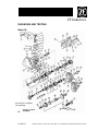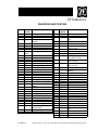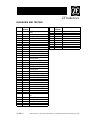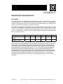
1
TRANSMISSION ZF S5-42
TROUBLESHOOTING GUIDE-SERVICE TIPS
ZF Industries
DESCRIPTION AND OPERATION
Description
The model number for the ZF transmission (7003) is S5-42. This model number can be divided
into three parts. First, “S” designates a synchronized transmission. Second, “5” designates the
number of forward gears. Finally, “42” is the approximate maximum input torque capacity in tens
of ft-lb. In this case 42 equals 420 ft-lb. input torque capacity.
The S5-42 ZF transmission is available in both wide ratio and close ratio versions. The wide
ratio version is available for all F-Series vehicles over 8500 lbs GVW, all engines (6007), except
F-Super Duty Commercial Stripped Chassis equipped with a diesel engine. The close ratio
version is available only in F-Series vehicles with a 7.3L diesel engine and a GVW over 8500
lbs. The ratios are as follow:
Close Ratio
(Diesel)
Wide Ratio
(Gasoline / Diesel)
1st
4.14
2nd
2.37
3rd
1.42
4th
1.0
5th
0.77
Reverse
3.79
5.72
2.94
1.61
1.0
0.76
5.24
The transmission features an aluminum case (7005) with an integral clutch housing. Because of
the aluminum case, the tapered roller bearings of the transmission shafts must be fitted under
preload. This is because heat expansion of the aluminum case is greater than that of the steel
alloy mainshaft and countershaft cluster gear (7113). If the bearings were not pre-loaded, this
would result in excessive end play when the case in warm, loaded operating conditions. The
transmission also features shrink-fit gears on the countershaft cluster gear. Shrink-fit gears are
connected to the countershaft cluster gear by friction only, rather than connected trough splines.
The gear is heated and lightly pressed onto the countershaft cluster gear. The subsequent
cooling of the gear provides the shrink fitting. The countershaft cluster gear is serviced as an
assembly.
07-03B-1
1994 Econoline / F-150, F-250, F-350 / Bronco / F-Super Duty Powertrain, Drivertrain Aug 1993
TRANSMISSION ZF S5-42
TROUBLESHOOTING GUIDE-SERVICE TIPS
ZF Industries
DIAGNOSIS AND TESTING
Inspection and Verification
A troubleshooting guide has been put together to assist diagnosing transmission-related
problems. Use the transmission noise evaluation procedure and troubleshooting guides on the
following pages, or refer to Section 07-00 in the 1994 Ford Service Manual. Also refer to Section
08-00 in the 1994 Ford Service Manual. Remember, it is important to get an accurate description
of the complaint before any diagnosis can be performed. Ask questions as to whether it occurs
hot or cold, during shifting, driving at a particular speed or in a particular gear. If possible, have
the customer demonstrate the concern.
Cold Transmission
• Drive the truck in all gears (1-5 and reverse gears).
• Evaluate the noise in neutral. Check if there are any noise changes in a particular gear, i.e.,
4th gear. In 4th gear the countershaft is not under load.
• Check if the noise increases when the transmission is warming up.
• See if the noise is related to engine speed, road speed or gear selection.
Warm Transmission
• Check all gears plus reverse gear and make note of any noise changes in a particular gear.
• Check noise in neutral while parked. Check if the noise disappears at a certain engine rpm or
with the clutch pedal (7519) depressed.
• Drive in the gear in which the noise is most noticeable. Press in the clutch and leave the gear
engaged. If the noise changes or disappears, the noise may be amplified by the vibration of
the engine.
• Drive under the same condition again. Press the clutch pedal in and shift into neutral.
Release the clutch while the truck is coasting down the road. Evaluate the noise, as the rear
axle assembly (4006) turns the mainshaft.
07-03B-2
1994 Econoline / F-150, F-250, F-350 / Bronco / F-Super Duty Powertrain, Drivertrain Aug 1993
TRANSMISSION ZF S5-42
TROUBLESHOOTING GUIDE-SERVICE TIPS
ZF Industries
DIAGNOSIS AND TESTING
ADDITIONAL TESTING FOR 4X4 TRUCKS (Non-Electronic Shift)
• Check for any noise change when shifting the transfer case (7A195) between 4X2, 4 high, 4
low or into neutral.
• With the vehicle at a complete stop and the transfer case in neutral, shift through all the
gears and evaluate noise at different engine rpm. Check for any noises in neutral at different
engine rpm.
NOTE:
To isolate clutch concerns from transmission concerns, operate the transmission at no-load. On
4X4 models, place the transfer case in neutral. Remove the driveshaft on 4X2 models. Run the
engine at 3000 rpm and operate the transmission throughout ranges with the clutch engaged. If
hard shifting concern (power to transmission) disappears, the concern may be in the clutch
system. An improperly operating clutch can result in hard shifting that is most noticeable in 1st,
2nd and reverse. The hydraulic release mechanism must work properly. Continued operation
with a defective clutch system may result in premature wear or damage of synchronizer (7124).
Hard shifting or difficulty engaging gears may be the result of improper clutch function. Check
the release system travel. Minimum travel for the concentric slave cylinder bearing (4.9L and
5.8L engines) and the external system slave cylinder push rod (7.3L and 7.5L engines) is 11 mm
(7/16 inch). If system travel is less than 11 mm, this is an indication of problems in the release
system such as excessive flexing of the instrumental panel (04320), cracked instrumental panel
reinforcement at the clutch master cylinder mounting and air or water in the hydraulic clutch
hose (7T504). Refer to Section 08-00 in the 1994 Ford Service Manual.
If release system is greater than 11 mm, and the clutch is suspected, check for clutch reserve as
follow:
1. Set the parking brake control (2780) and put the transmission in neutral.
2. With the clutch pedal fully depressed, shift into reverse, then shift half way between reverse
and neutral to defeat the synchronizer.
3. Allow the clutch pedal to fully return and adjust the position of shift control selector lever and
housing (7210) to obtain light contact between the gear teeth. A slight grind will occur.
4. Slowly depress the clutch pedal until grinding stops. Measure the clutch pedal travel from
this position to the full down position (clutch reserve position).
This clutch reserve dimension should be at least 1 1/2 inches. If the reserve is less than 1 1/2
inches, and there are no hydraulic control system concerns, remove the transmission and check
for excessive clutch wear. On the 7.3L diesel and 7.5L engines, check for contamination of
clutch release hub and bearing (7548) and binding on the bearing retainer. Replace the clutch
assembly or clutch release hub and bearing as required.
NOTE:
On the 4.9L and 5.8L vehicles, the case is ribbed in order to reduce gear and gear roll-over
noises.
07-03B-3
1994 Econoline / F-150, F-250, F-350 / Bronco / F-Super Duty Powertrain, Drivertrain Aug 1993
TRANSMISSION ZF S5-42
TROUBLESHOOTING GUIDE-SERVICE TIPS
ZF Industries
DIAGNOSIS AND TESTING
Symptom Chart
Noise While Stopped — Transmission in Neutral
CONDITION
POSSIBLE CAUSE
ACTION
Noise present with clutch pedal
fully depressed.
• Engine noise.
• Refer to appropriate Shop
Manual for these areas.
• Clutch release hub and
bearing failure.
• Pilot bearing failure.
• Misaligned transmission.
Noise disappears when engine
RPM exceeds 1500 without
depressing clutch pedal.
Noise present at engine speeds
above idle.
• Neutral rollover is caused by
the engine firing pulses
transmitted through the gear
set. Some neutral rollover is
normal on the 7.5L
application. The dual mass
flywheel on the 7.3L Diesel
and the two stage clutch on
the 4.9L & 5.8L should
eliminate this concern on
these engines.
• Insufficient lubrication.
• Damaged tapered roller or
needle bearing.
• Scuffed gear tooth contact
surfaces.
07-03B-4
• Check engine idle quality and
speed. A rough or low idle will
aggravate this concern.
• Drain oil (when required) and
fill with the correct oil,
conforming to Ford’s
specification ESP M2C-166H.
Type “H” or MERCON®
(Motorcraft).
• Inspect for failure. Pay
special attention to the
mainshaft front bearing
(pocket bearing), located
between the input shaft and
mainshaft. Turn the gears on
the mainshaft to check for
failure of needle bearing
failure by feeling for
roughness.
• Disassemble transmission
and check gear tooth contact
surfaces. Replace gears as
required.
1994 Econoline / F-150, F-250, F-350 / Bronco / F-Super Duty Powertrain, Drivertrain Aug 1993
TRANSMISSION ZF S5-42
TROUBLESHOOTING GUIDE-SERVICE TIPS
ZF Industries
DIAGNOSIS AND TESTING
Symptom Chart
Noise While Stopped — Transmission in Neutral (Continued)
CONDITION
POSSIBLE CAUSE
ACTION
Noise on PTO equipped
• Incorrect PTO gear mash due • Check the mating teeth on
transmissions. Remove the PTO
to: Wrong model PTO,
transmission countershaft
and install a cover plate.
incorrect installation, defective
gear and also on the input
Evaluate for noise without PTO.
PTO.
shaft gear for damage. If any
parts are damaged, replace
damaged transmission parts.
Contact PTO
supplier/manufacturer to
verify model usage, shimming
and PTO quality.
CONDITION
Noise While Driving
POSSIBLE CAUSE
ACTION
Noise is present in all or several • Worn or rough mainshaft rear
gears. Noise occurs at high and
bearing.
low engine speeds and may vary
with engine speed.
• Needle bearing under
mainshaft gears damaged.
• Wrong preload on main or
cluster shaft bearing.
• PTO installed incorrectly.
‘Rattle’ noise when taking off
• ‘Lugging Rattle’.
from a stop and driving at less
than 1000 RPM.
‘Clunking’ noise when shifting or
speeding up or slowing down.
Condition is worse on bumpy
surface.
Noise while driving in one gear
increases with road speed.
07-03B-5
• Disassemble transmission
and install new output shaft
rear bearing on mainshaft.
• Replace needle bearing and
gear.
• Disassemble transmission
and correct preload.
• Check PTO installation.
• Operate truck without
‘lugging’. Condition will
shorten the life of the
transmission.
• Freeplay in the system (clutch • Check for excessive axle
through axle and fuel injector
backlash. Clunk cannot be
shutoff timing). Some clunk is
corrected by repairing
normal with the 4.9L & 5.8L
transmission unless a
engines.
transmission defect is
evident.
• Loose yoke nut.
• Install a new Spiral Locknut.
No staking required. Tighten
to 270 Nm or 200 ft-lb.
• Worn, imperfect or chipped
• Replace affected mating
gear teeth on the affected
gears.
gear.
1994 Econoline / F-150, F-250, F-350 / Bronco / F-Super Duty Powertrain, Drivertrain Aug 1993
TRANSMISSION ZF S5-42
TROUBLESHOOTING GUIDE-SERVICE TIPS
ZF Industries
DIAGNOSIS AND TESTING
Symptom Chart
Noise While Driving (Continued)
CONDITION
POSSIBLE CAUSE
‘Whining’ noise at high engine
RPM in 3rd and 5th gear.
• Worn input shaft gear and
countershaft drive gear.
Shift lever ‘buzz’ present while
driving, not present during a
neutral engine run up while
parked.
• Upper shift lever damaged or
loose.
• Lower shift lever defective.
Shifter lever ‘rattle’ in neutral
engine run up, primarily diesel
4X4.
• Transfer case shift lever may
not have plastic bushing at
the pivot.
• Transmission lever boot
incorrectly installed.
07-03B-6
ACTION
• Check noise level in 4th gear
under same engine
conditions. If noise level is
less, replace the input shaft
and countershaft. Inspect and
replace other gears as
required.
• Change shift lever. If ‘buzz’ is
still present, see which gear
buzz occurs. Disassemble
and inspect specific gear.
Inspect and replace other
gears as required.
• Replace lower shift lever.
Shift lever E9TZ-7210-G is
less sensitive to vibration
than earlier design.
• Check by temporarily
removing the transfer case
shift lever. Replace if the
noise is gone.
• Lever boot must make air
tight seal to shift lever.
Replace boot if stretched or
sealing surface is damaged.
1994 Econoline / F-150, F-250, F-350 / Bronco / F-Super Duty Powertrain, Drivertrain Aug 1993
TRANSMISSION ZF S5-42
TROUBLESHOOTING GUIDE-SERVICE TIPS
ZF Industries
DIAGNOSIS AND TESTING
Symptom Chart
Noise While Driving (Continued)
CONDITION
POSSIBLE CAUSE
Moan or vibration on F-Super
• Aftermarket modifications to
Duty at road speeds greater than
frame or driveshaft.
50 MPH.
Hard shift (particularly 1st, 2nd & • Clutch not releasing
reverse).
completely.
• Operator not fully depressing
clutch pedal.
• Flexing of instrumental panel.
• Hydraulic clutch hose routed
too close to exhaust manifold.
• Air/water in hydraulic clutch
hose.
• Insufficient reserve of
synchronizer (a defective
clutch system can a result in
premature loss of
synchronizer reserve).
07-03B-7
ACTION
• Non-factory driveshafts
should be inspected for:
• Size
• 0 to 51 inches long - 3 inch
diameter tube is OK.
• Up to 55 inches long - 3 1/2
inch diameter tube is
required.
• Up to 59 inches long - 4 inch
diameter tube is required.
• Working angles greater than
1/2º but less than 3º.
• System balanced to within 0.4
in/oz at the ends and 0.8
in/oz at the driveshaft center
bearing bracket.
• See clutch procedure at the
end of this diagnosis guide, or
Section 08-00 in the 1994
Ford Service Manual.
• Interview operator.
• Repair instrumental panel.
• Move or shield hydraulic
clutch hose.
• Bleed clutch system.
• Replace complete
synchronizer and
corresponding gear, if
required.
1994 Econoline / F-150, F-250, F-350 / Bronco / F-Super Duty Powertrain, Drivertrain Aug 1993
TRANSMISSION ZF S5-42
TROUBLESHOOTING GUIDE-SERVICE TIPS
ZF Industries
DIAGNOSIS AND TESTING
Symptom Chart
Shift Concerns
POSSIBLE CAUSE
CONDITION
Notchy shifting.
• Some notchiness is normal
(especially in 3rd gear).
‘Grinding’ noise during shifting.
•
•
•
Walking or jumping out on rough •
roads.
•
Note whether the unit walks out •
of gear under drive or on a coast •
load. Also, does the ‘walkout’
occur on smooth or only on
rough roads? A number of items •
that would prevent full
engagement of gears are:
07-03B-8
ACTION
• For excessive notchiness
replace with revised
synchronizers:
1/2 FOTZ-7124-D
3/4 FOTZ-7124-E
5/R FOTZ-7124-C
Synchronizer cone too
• Do 3 to 5 hard shifts with high
smooth (after a few thousand
engine RPM. If noise is still
miles).
present, disassemble and
check for damage (darkened
patches OK). Refer to
Synchronizer Ring /
Synchronizer Body Wear.
Synchronizer ring defective.
• Change synchronizer.
Insufficient wear limit of
• Change synchronizer.
synchronizer ring.
Interference or resistance in
• Remove and disassemble
the mechanism preventing full
transmission and check
engagement of the sliding
profile of internal grooves in
collar.
the sliding sleeve.
If sliding collar has been
• Check for shift lever
shifted completely into
interference. The stub lever,
position, some other
gear shift finger or shift forks
malfunction could move
could be worn. Remove
sliding collar and shift control
transmission and replace
selector lever out of its proper
damaged parts.
location.
Worn or loose engine mounts. • Check engine mounts.
Shift fork pads or groove in
• Remove and disassemble
sliding collar worn
transmission and replace
excessively.
damaged parts.
Transmission and engine out • Make sure transmission is
of alignment either vertically
tightly bolted to the engine.
or horizontally.
1994 Econoline / F-150, F-250, F-350 / Bronco / F-Super Duty Powertrain, Drivertrain Aug 1993
TRANSMISSION ZF S5-42
TROUBLESHOOTING GUIDE-SERVICE TIPS
ZF Industries
DIAGNOSIS AND TESTING
Symptom Chart
CONDITION
Shift Concerns (Continued)
POSSIBLE CAUSE
ACTION
Walk or jump out on rough roads. • Use of heavy shift lever
extensions.
Excessive shift control selector
lever movement in 3rd gear.
Gear cannot be engaged.
07-03B-9
• Use original equipment shift
lever and housing. Install
heavy duty detent springs
(E8TZ-7E218-A).
• Shift interlock springs broken • Remove detent spring plug
or missing.
on detent and replace shifter
interlock springs.
• Detent spring cap not pressed • Replace with new detent
in property.
spring plug and press in 1
mm (3/64 inch).
• No preload in drive gear,
• Remove and disassemble
mainshaft or countershaft,
transmission and replace
caused by worn bearings.
defective bearings (necessary
to reset bearing preload).
• Grated selector teeth.
• Change synchronizer and
gear.
• 3-4 synchronizer body snap
• Disassemble and replace
ring not seated in groove on
affected parts, paying special
output and fifth gear
attention to 3-4 synchronizer,
driveshaft.
input gear, input shaft pocket
bearing and shift fork.
• Clutch not releasing (see hard • Check clutch per procedure
shift).
at the end of this diagnosis
guide, or Section 08-00 in the
1994 Ford Service Manual.
• Gear selector interlock sleeve • If bent or damaged, replace
jammed in transmission.
the gear selector interlock
sleeve.
• Damage to teeth on sliding
• Replace or correct
collar or improper installation
synchronizer. Check for
(dog teeth worn).
damage on the corresponding
mainshaft gear in clutch teeth
area. Replace as required.
• Jammed pressure pieces in
• Remove and disassemble
synchronizer.
transmission and replace
pressure pieces.
• Shift rails out of proper
• Replace all shift rails, detents
position.
and gear selector interlock
sleeve.
1994 Econoline / F-150, F-250, F-350 / Bronco / F-Super Duty Powertrain, Drivertrain Aug 1993
TRANSMISSION ZF S5-42
TROUBLESHOOTING GUIDE-SERVICE TIPS
ZF Industries
DIAGNOSIS AND TESTING
Symptom Chart
CONDITION
Sticking in gear.
Stuck in gear.
High shift efforts.
07-03B-10
Shift Concerns (Continued)
POSSIBLE CAUSE
ACTION
• Clutch not releasing (see hard • Check clutch per procedure
shift above).
at the end of this diagnosis
guide, or Section 08-00 in the
1994 Ford Service Manual.
• Gear selector interlock sleeve • If bent or damaged, replace
jammed in transmission.
the gear selector interlock
sleeve.
• Sliding collar tight on splines • Remove and disassemble
(dog teeth damaged).
transmission.
• Shift rails out of proper
• Replace all shift rails, detents
position.
and gear selector interlock
sleeve.
• Lack of lubricant or wrong
• Inspect through the PTO
lubricate used, causing buildopenings. If sludge is present,
up of sticky and sludgy
remove and clean the
deposits on splines of sliding
transmission.
collar.
• Case bushing rough, or
dragging.
• Clutch not releasing (see hard • Place transmission in 4th
gear and rotate the mainshaft
shift above).
by hand while the clutch is
depressed. If a roughness is
felt, remove the case
bushing, inspect and replace
the bearing and input shaft, if
required (input bearing
preload must be reset if input
shaft is replaced).
• Install a new input shaft and
• Damaged input shaft pocket
input shaft pocket bearing
bearing.
(necessary to reset bearing
preload).
1994 Econoline / F-150, F-250, F-350 / Bronco / F-Super Duty Powertrain, Drivertrain Aug 1993
TRANSMISSION ZF S5-42
TROUBLESHOOTING GUIDE-SERVICE TIPS
ZF Industries
DIAGNOSIS AND TESTING
Symptom Chart
CONDITION
Shift Concerns (Continued)
POSSIBLE CAUSE
ACTION
High shift effort in one gear only. • Sliding sleeve tight on splines. • Remove transmission and
replace affected
synchronizer.
• Synchronizer teeth chipped or
badly mutilated.
• Remove and disassemble
transmission and replace
damaged parts.
• Binding or interference of shift
control selector lever with
• Check shift operation in cab.
other objects or rods inside
the cab.
• Mainshaft gears, seized or
galled on either the thrust
• Remove and disassemble
face or diameters.
transmission, replace
synchronizer and other
affected parts.
• Synchronizer (wear limit too
low, fractures).
• Remove and disassemble
transmission, replace
synchronizer and other
affected parts.
• Synchronizer cone
smoothness.
• Make 3 and 5 hard shifts with
high engine RPM.
High shift efforts in cold weather, • Incorrect hi-viscosity fluid.
• Install Type H or MERCON®
all gears.
fluid. Road test the vehicle to
identify possible damage
caused by the wrong fluid.
Synthetic MERCON® E6AZ19582-B will improve cold
weather shiftability.
07-03B-11
1994 Econoline / F-150, F-250, F-350 / Bronco / F-Super Duty Powertrain, Drivertrain Aug 1993
TRANSMISSION ZF S5-42
TROUBLESHOOTING GUIDE-SERVICE TIPS
ZF Industries
DIAGNOSIS AND TESTING
Symptom Chart
CONDITION
Leak at case cover.
Leak at transmission case plug.
Leak at transfer case cover.
Leak at detent spring plug.
Leak Concerns
POSSIBLE CAUSE
• Re-used or damaged case
cover gasket.
• Sealing ring missing from
transmission case plugs
(transmissions with an E9TA
prefix or later have a sealing
surface machined on the
housing).
• (Transmissions with an F4TA
prefix have a sealing ring on
the plug with rubber centering
feature for improved sealing).
• Bolts loose or damaged
transmission case deflector
gasket.
• Re-used or damaged detent
spring plugs.
Leak at large welch plug inside
clutch housing. Look for cracks
around the hole.
• Improper assembly.
Leak at input shaft bearing oil
passage plug (inside clutch
housing w/7.5L & 7.3L engines
and on left side w/4.9L & 5.8L
engines).
Leak at output shaft oil seal.
• Improper assembly.
Leak at input oil seal.
• Improper assembly. Seal lip
may have rolled during
assembly, garter spring may
have become dislodged
during a previous repair.
07-03B-12
• Output yoke nut loose or
improperly staked (4X2,
except F-Super Duty).
ACTION
• Replace with new case cover
gasket. Never use RTV.
• Install a new sealing ring.
• Install a new sealing ring.
• Replace transmission case
deflector gasket, tighten bolts
to 38 Nm (28 ft-lb).
• Use new detent spring plugs
when reassembling. Do not
deform case around detent
spring plug to retain.
• Reseal, using anaerobic
sealant E2AZ-19562-B
(WSK-M2G348-A5). If
cracked, replace flywheel
housing.
• Reseal, using anaerobic
sealant E2AZ-19562-B
(WSK-M2G348-A5). If
cracked, replace flywheel
housing.
• Replace seal, using a new
locknut. Torque to 270 Nm
(200 ft-lb).
Caution: Do not re-use locknut.
• Replace front pump support
seal using extreme caution
that input shaft does not
contact the oil seal during
reassembly (if the seal lip is
rolled, leaking may not occur
for several hundred miles).
1994 Econoline / F-150, F-250, F-350 / Bronco / F-Super Duty Powertrain, Drivertrain Aug 1993
TRANSMISSION ZF S5-42
TROUBLESHOOTING GUIDE-SERVICE TIPS
ZF Industries
DIAGNOSIS AND TESTING
Symptom Chart
CONDITION
Leak Concerns (Continued)
POSSIBLE CAUSE
Leak between quill pipe and
flywheel housing (7.3L and 7.5L
engines only).
• Damaged O-ring during
assembly.
Leak at case joint.
• Damaged mating surfaces or
assembly error.
CONDITION
Cracked flywheel housing.
Miscellaneous Concerns
POSSIBLE CAUSE
• Drivetrain vibration:
• Caused by assembly error.
• Vehicle modification
(driveshaft lengthened or
shortened).
Cracked rear engine mount
transmission attachment ears.
• Broken front engine mounts.
• Vibration caused by a
driveline imbalance.
• Rear mount upper flange not
flat.
07-03B-13
ACTION
• Remove quill pipe, inspect
sealing surfaces and replace
O-ring. Lubricate O-ring prior
to assembly to prevent
damage.
• Repair or replace damaged
case. Reseal with anaerobic
sealant E2AZ-19562-B
(WSK-M2G348-A5). Torque
bolt to 22 Nm (16 ft-lb).
ACTION
• Check the integrity of
driveshaft attachment.
• Non-factory driveshafts
should be inspected for:
• Size
• 0 to 51 inches long - 3 inch
diameter tube is OK.
• Up to 55 inches long - 3 1/2
inch diameter tube is
required.
• Up to 59 inches long - 4 inch
diameter tube is required.
• Working angles greater than
1/2º but less than 3º.
• System balanced at 3000
RPM to within 0.4 in/oz at the
ends and 0.8 in/oz at the
center support.
• Inspect and replace front
engine mounts if required.
• See above.
• Replace rear mount.
1994 Econoline / F-150, F-250, F-350 / Bronco / F-Super Duty Powertrain, Drivertrain Aug 1993
TRANSMISSION ZF S5-42
TROUBLESHOOTING GUIDE-SERVICE TIPS
ZF Industries
DIAGNOSIS AND TESTING
Symptom Chart
Bearing Failure
POSSIBLE CAUSE
CONDITION
NOTE: The service life of
most transmissions is
governed by the life of the
bearings. The majority of
bearing failures can be
related to driveline vibration
or contamination of the fluid.
Additional reasons for
bearing failures are:
Extended start-up idle in extreme
cold may lead to wear of input shaft
pocket bearing.
•
•
Any combination of operation at or
above GVW in high ambient
temperatures, on steep grades, or
vehicles with high frontal areas
(exceeding 60 square feet) can affect
all bearings due to temperature
build-up.
•
Input shaft pocket bearing not
lubricated due to missing, damaged
or misinstalled front bearing oil scoop
ring.
NOTE: This guide does not
apply to vehicles equipped
with IDI turbo diesel engines.
•
•
Input shaft pocket bearing not
lubricated due to damaged oil baffle.
•
•
Damage due to towing a vehicle
greater than 50 miles or at speeds
exceeding 35 MPH with the
driveshaft installed. Third gear
bearings are especially susceptible
to damage.
Vibration break-up of retainer and
brinelling of races-fretting corrosion.
•
Incorrect preload causes faster
wearing of the bearings, due to
incomplete contact area.
Lack of lubricant or wrong type.
•
Acid etch of bearing due to water in
lube.
Worn out due to other part failure.
•
•
•
•
•
•
07-03B-14
ACTION
•
•
•
•
•
Synthetic MERCON® E6AZ-19562-B
(ESR-M2C 163-AZ) provides
improved lubrication when
transmission temperatures remain
below minus 20º F for extended
periods.
Heat build-up may cause break down
of the ATF. Synthetic MERCON®
can withstand higher operating
temperatures.
Replace damaged components and
make sure of proper installation of
front bearing oil scoop ring. Check
for proper installation of the snap
ring, which retains the 3-4
synchronizer, on the mainshaft next
to the front bearing oil scoop ring.
Replace damaged components
making sure the front bearing oil
scoop ring is not damaged during
reassembly.
Provide correct towing procedures to
tow operator.
Refer to restrictions of mainshaft in
the Miscellaneous Concern chart of
this diagnosis guide.
Be sure to follow preload setting
procedure in this section.
Check for leaks and repair as
required. Replace with correct fluid.
Identify and correct source of water
entry.
Remove, disassemble and clean the
transmission then replace damaged
parts (necessary to reset bearing
preload if any input shaft bushings
are replaced).
1994 Econoline / F-150, F-250, F-350 / Bronco / F-Super Duty Powertrain, Drivertrain Aug 1993
TRANSMISSION ZF S5-42
TROUBLESHOOTING GUIDE-SERVICE TIPS
ZF Industries
DIAGNOSIS AND TESTING
Model S5-
* Serviced as a complete
sub assembly
42
07-03B-15
1994 Econoline / F-150, F-250, F-350 / Bronco / F-Super Duty Powertrain, Drivertrain Aug 1993
TRANSMISSION ZF S5-42
TROUBLESHOOTING GUIDE-SERVICE TIPS
ZF Industries
DIAGNOSIS AND TESTING
Item
1
2
3
4
5
6
7
8
9
Part
Number
7277
7D152
N603264
7262
10
11
12
13
14
15
16
17
18
19
20
21
22
23
24
7207
7210
7C371
—
7A443 &
7C015
7203
7E218
7185
7F194
7234
7B096
7B096
7L013
7N120
7247
7005
7L018
7A010
7B602
7166
25
26
27
28
29
30
31
32
33
34
7165
304650
15520
7L101
7A010
—
7D362
7288
7080
7052
35
36
7029
7040
07-03B-16
Description
Gearshift Lever Boot
Snap Ring
Capscrew
Gearshift Lever Boot
Retainer
Gasket
Shift Control Selector Lever
Guide Piece
Guide Piece
Hex Bolts and Washers
Shift Control Housing
Shift Detent Plunger Assy
Gasket
5th-Reverse Interlock
Shifter Interlock Spring
Interlock Roll Pin
Interlock Roll Pin
Detent Spring Plug
Spring
Shift Rail Detent Plunger
Case
Case Plug
Transmission Case Plug
Clutch Release Lever Stud
Transmission Case PTO
Gasket
PTO Cover
Bolt
Backup Lamp Switch
Sealing Ring
Transmission Case Plug
ID Plate (Part of 7003)
Central Shift Rail Bearing
Shifter Shaft Seal
Release Bearing Guide Tube
Input Shaft and Extension
Housing Seal
Input Bearing Front Shim
Oil Baffle
Item
Part
Description
Number
37 7025
Case Bearing
38 7017
Input Shaft
38A 7046
Front Bearing Oil Scoop
Ring
39 7120
Input Shaft Pocket Ring
40 7B331
Small Parts Repair Kit
41 —
Gear Synchronizer Ring
(Part of 7124)
42 —
Ball (Part of 7B331)
43 7124
Synchronizer
44 —
Spring (Part of 7B331)
45 —
3rd Gear Synchronizer
Body (Part of 7124)
46 —
3rd Gear Synchronizer Ring
(Part of 7124)
47 —
3rd-4th Sliding Sleeve
(Part of 7124)
48 7186
3rd Gear
49 7133
Caged Needle Roller
Bearing
50 7173
3rd Speed Bearing Spacer
51 7114
Thrust Washer
52 7103
2nd Gear
53 7133
1st Speed Gear Bearing
54 7B331
Small Parts Repair Kit
55 7124
2nd Gear Synchronizer Ring
56 7124
Ball
57 7124
Pressure Piece
58 7124
Spring
59 7124
1st-2nd Synchronizer Body
60 7124
1st Gear Synchronizer Ring
61 7124
1st-2nd Sliding Sleeve
62 7100
1st Gear
63 7127
3rd Gear Bearing
64 7061
Mainshaft
65 7127
Reverse Gear Baering
66 7142
Output Shaft Reverse Gear
67 7124
Reverse Gear Synchronizer
Ring
68 7124
Ball
69 7124
Pressure Piece
70 7124
Spring
1994 Econoline / F-150, F-250, F-350 / Bronco / F-Super Duty Powertrain, Drivertrain Aug 1993
TRANSMISSION ZF S5-42
TROUBLESHOOTING GUIDE-SERVICE TIPS
ZF Industries
DIAGNOSIS AND TESTING
Item
71
72
73
74
75
76
77
78
79
80
81
82
83
84
85
86
87
88
89
90
91
92
93
94
95
96
97
98
99
100
101
102
103
105
106
108
109
Part
Description
Number
7124
5th-Reverse Synchronizer
Body
7124
5th Gear Synchronizer Ring
7124
5th-Reverse Sliding Sleeve
7B331
Small Parts Repair Kit
7121
5th Gear Bearing
7158
5th Gear
7R205
Output Shaft Rear Bearing
7072
Spacer
7D362
Central Shift Rail Bearing
7E290
Magnet
—
Dowel (Part of 7003)
7A443
Bolt
7A039
Extension Housing (4X2)
7052
Input Shaft and extension
Housing Seal
7089
Output Yoke (4X2)
7045
Output Yoke Locknut (4X2)
7A039
Extension Housing (4X4)
7B331
Small Parts Repair Kit
7052
Input Shaft and Extension
Housing Seal
7119
Thrust Washer
7065
Output Shaft Bearing
7064
Output Shaft Snap Ring
7113
Countershaft Drive Gear
7113
Countershaft 3rd Gear
7113
Countershaft Cluster Gear
7113
Countershaft 5th Gear
7064
Output Shaft Snap Ring
7065
Output Shaft Bearing
7140
Reverse Idler Gear Shaft
7E139
Reverse Idler Gear Bearing
7141
Reverse Idler Gear
7214
Reverse Idler Gear Shaft
Bolt
7K267
Sealing Ring
7240
Main Gear Shift Rail
7243
Gear Shift Finger
7B096
Roll Pin
7B096
Roll Pin
07-03B-17
Item
110
111
112
113
114
115
116
117
118
119
Part
Number
7230
7241
7242
7231
7B096
7A443
7K201
7B096
7358
7239
Description
3/4 Shifter Fork
3/4 Reverse Shift Rail
5/Rev Shift Rail
5/Rev Shift Fork
Roll Pin
Bolt (3)
Gear Selector Interlock Plate
Roll Pin
1/2 Shift Rail
1/2 Shift Fork
1994 Econoline / F-150, F-250, F-350 / Bronco / F-Super Duty Powertrain, Drivertrain Aug 1993