1
US 8,689,376 B2
Page 2
(56)
References Cited
W0
WO 01/85085 A2
11/2001
W0
WO 2004/093023 A2
10/2004
U.S. PATENT DOCUMENTS
4,882,566 A
OTHER PUBLICATIONS
11/1989 Koerber, Sr. et al.
4’907’845 A
3/1990 WOOd
4,998,939 A
3/1991
8/1992 Nonon
3/1993 Travis
regarding PCT/US06/043290, the international counterpart to the
present application that includes the same claims as the present
5,276,432 A
5,319,355 A
1/1994 Travis
6/1994 Russek
application.
Stryker Adel 500XL Childbearing Bed Service Manual, Adel Medi
5,319,363 A *
6/1994 Welch et al. ................. .. 340/8.1
cal Ltd, 1986‘
5 137 033 A
531953198 A
2
PCT Written Opinion of the International Searching Authority
Potthast et al.
.
g?ggégggiln et 31
5,450,639 A
2003
9/ 1997 Bell et al,
11/1997 Laganiere et al.
2
Advantage Stretchers Stryker Patient Handling, May 1994.
Stryker Medical Labor & Delivery Model 5000 Series, Oct. 1996.
EnlrllIlCh et 31' l
6’014’346 A *
10000 133108;): et a '
6,014,784 A
1/2000
*
6,240, 579 B1
.
Adel Maternity Bed Model 4700 & 5012 Operations Manual, Oct.
9/1995 Weismiller 61 al.
5,664,270 A
5,689,839 A
.
Hausted Gemini Series, Hausted, Inc., Oct. 1993.
368/10
Taylor et al. .................... .. 5/713
6/2001 Hanson et 31,
Stryker Adel 2100EC Childbearing Bed, Stryker Patient Care, Jan.
1994
_
_
_
Adel 500XL Chlldbearlng Bed, Stryker Pat1ent Care, May 1995.
6,320,510 B2 *
11/2001 Menkedick et al. ..... .. 340/686.1
Singaporean Of?ce Action mailed Mar. 19, 2010 for Serial No. 2008/
6,822,571 B2
11/2004 Conway
03045.4. a foreign counterpart to the present application (including
6,829,796 B2 *
12/2004 salvatini et 3L ~~~~~~~~~~~~~~~~ ~~ 5/713
7’533’429 B2
7,594,286 B2 *
8,1 17,701 B2
8,464,380 B2
5/2009 Ménkedlck et al'
9/2009
Wllllams ........................ ..
2000 Bobey et al‘
6/2013 Bobey et al‘
5/424
Austrian Patent Of?ce Written Opinion),
The current claims of Singapore Application No. 2008/03045.4.
_
_
_
_
_
An Of?ce Action for Singaporean patent application serial No.
200803045 .4 Which is the foreign counterpart to the present applica
2002/0059679 A1 *
5/2002 Weismiller et al. ............. .. 5/610
2004/ 0103475 A1
6/ 2004 Ogawa et al.
Search report and written opinion of EP Application No. 068275965,
2005/0035871 A1*
2/2005 Dixon et al. ............. .. 340/686.1
dated May10,2010,
2006/0049936 A1 *
2006/0101581 A1*
2006/0279427 A1
2007/0076852 A1
2007/0210917 A1
3/2006 Colllns et al~ ~~
5/2006
ti°n~
Claims of EP 068275965, as ofMay 10, 2010.
Blanchard et al. .............. .. 5/713
12/2006 B e Cker et 31
4/2007 Ishikawa et 'aL
9/2007 Collins, Jr. 61 al.
FORETGN PATENT DOCUMENTS
,
and Low-Air-Loss Therapy, and Mattress Replacement Systems,
May 2005
Plexus Medical Service Manual for 02 Zoned C4000 Portable Rota
tion System and CareMedx C5000 Multi-Zoned Low Air Loss
Therapy System, Apr. 2003.
EP
W0
1477 110 A1
11/2004
WO 01/75834 A1
10/2001
.
Gayrnar AIRE-TWIN Operator s Manual for Alternating Pressure
* cited by examiner
US. Patent
Apr. 8, 2014
Sheet 1 0f 11
US 8,689,376 B2
US. Patent
Apr. 8, 2014
Sheet 2 0f 11
US 8,689,376 B2
US. Patent
Apr. 8, 2014
US 8,689,376 B2
Sheet 3 0f 11
74
FOOTBOARD
CONTROL PANE
@
l
l
l
I
92
72
NORMAL LAMP
j SIDERAIL
CONTROL
II
PANEL
W
UPPER
50
PORTION
70
CONTROLLER
J SIDERAII-
LOWER
BED
I
i
i[—'—'—'—
“
'—
FIRST
I}
SWITCH
“h
H
\56
“
II SECOND
II SIDERAIL
|\ SWITCH
'''' "_ ' — ' — ' — ' — '
THIRD
H SIDERAIL
I
l
PANEL
I
I
\Q/‘P PORTION ‘
CONTROL
l
I
48
OUTS|DE
l
‘
114!
86
INSIDE
|
NETWORK
INTERFACE —
_ ' — ' —
HEIGHT
|
5.14
I
\
=_
l
— ' — ' — ' — ' — “min—1
BED
‘
\
SIDERAIL
SBEiIAS'EER
HEIGHT
POT
\ \
\56
K58
k“
I‘ I\
SWITCH
‘
T
-
FOURTH
SIDERAIL
SWITCH
I \
I \
\
US. Patent
Apr. 8, 2014
Sheet 4 0f 11
US 8,689,376 B2
108w7
68
IZIEI J
@@
@J
110
FIG - 5
B: Status Alert =1
Side Rail
Brake
0: Status Alert :1
Ii) Bed Q:
:9
<1
LowHeight
le 4; eli> Exit Q]
74/
FIG - 6A
It} a @l
\74
0: Status Alert <:>]
7“
LowHeight
ILL-h
FIG - GB
US. Patent
Apr. 8, 2014
Sheet 5 0f 11
FIG - 7A
US 8,689,376 B2
FIG - 75
G: Status Alert <2]
CD
(,5
0: Status Alert E]
Brake
\74
FIG - 8A
-)
4
\74
FIG - 8B
[E Status Alert :1
Ii>
74
[E Status Alert :J
Side Rail I}
74
US. Patent
Apr. 8, 2014
Sheet 6 0f 11
US 8,689,376 B2
FIG - 9A
[I Status Alert :1
\74
FIG - 9B
[':> Status Alert :0
US. Patent
Apr. 8, 2014
Sheet 7 0f 11
US 8,689,376 B2
US. Patent
Apr. 8, 2014
Sheet 8 0f 11
7‘4
(
108\
*
|
l
'
\
l
'
l €:>Main Menu
Gain / Loss
'
US 8,689,376 B2
1I
A
Change Weight
Backlighting
1
EXlT
A
X
V
ENTER
I
"
V
\
1|
,
108
74
\
I
(
[:> Message
1J.H A5?
Do Not
Touch Bed
FIG-13
US. Patent
Apr. 8, 2014
Sheet 9 0f 11
Nurse Call System
US 8,689,376 B2
I
I
I
I
I
I
_____________________________ __I
l
|
El
Messaging
I
lnten‘
:
(HW/
|
Wireless Router/
Access Point
““““““ 3 -Wi-Fi (802.11a,b,g)
Digital
l
'
I
IE
Access Point
Wireless
:
-Wi-Fi (802.11a,b,g)
I
I
(
Netwqu (LAN)
‘
)
97
116
a?"
_
Asset
Tracking
Remote
Computer
Medical Records
FIG - 14
elCU
ADT System
US. Patent
Apr. 8, 2014
FIG - 15
Sheet 10 0f 11
US 8,689,376 B2
112
US. Patent
Apr. 8, 2014
Sheet 11 0f 11
EG
BwEa?w;
s_o{0Em6gm:?ka .
mvl2cejsi3g\uz%mNgw?f
52N2\ 9%
0t:.32oiw1lE:mxu2!rocqU
vrfm
E:owremnhvP
m;.
OE
O
cm:A wa?m:xmgm_\
2%2%._$
Em:
v66.“VEOJ.‘
smewzo~
US 8,689,376 B2
US 8,689,376 B2
1
2
PATIENT HANDLING DEVICE INCLUDING
patient and a plurality of sensors supported by the frame for
LOCAL STATUS INDICATION, ONE-TOUCH
FOWLER ANGLE ADJUSTMENT, AND
generating a plurality of sensor signals, wherein each sensor
signal corresponds to one of the features of the device. A
user-selectable control produces a control signal to initiate
POWER-ON ALARM CONFIGURATION
monitoring of the patient handling device. A controller is in
communication with the sensors and the user-selectable con
CROSS REFERENCE TO RELATED
APPLICATION
trol for receiving the control signal, acquiring the sensor
signals from the sensors in response to receiving the control
signal, and generating initial sensor data from the sensor
This application claims the bene?t of US. Provisional
Patent Application Ser. No. 60/734,083 ?led Nov. 7, 2005,
signals based on the initial state of the sensors. The controller
which is hereby incorporated by reference.
also periodically acquires the sensor signals from the sensors
and generates current sensor data from the sensor signals
based on the current state of the sensors. The controller then
compares the current sensor data to the initial sensor data and
alarms in response to a substantial variation between the
current sensor data and the initial sensor data.
BACKGROUND OF THE INVENTION
1. Field of the Invention
The subject invention relates to a patient handling device
A third aspect of the invention provides a patient handling
such as a hospital bed and associated methods of operation.
2. Description of the Related Art
Modern patient handling devices are becoming increas
ingly integrated with advanced electronic devices, such as a
20
microprocessors, communication busses, network interfaces,
corresponding to one of the features of the patient handling
wireless networks, high-tech displays, and advanced sensors.
These electronic devices have the potential to greatly enhance
patient care. But too often, these electronic devices are com
plex and do not adequately address ease of use, which can be
device having a plurality of features for patient care and a
frame for supporting a patient. A plurality of sensors are
supported by the frame, wherein each sensor senses a feature
of the patient handling device and generates a sensor signal
device. The patient handling device further includes a con
troller in communication with the plurality of sensors for
25
periodically acquiring the sensor signals from the plurality of
sensors to generate current sensor data. The controller also
compares the current sensor data to predetermined data. An
essential for patient care by accounting for the stresses of a
hospital/medical environment. As a result, modern patient
alert lamp in communication with the controller produces
handling device controls and user interfaces may be difficult
to operate.
light in response to a substantial variation between the current
in order to produce an alarm should the components be in a
non-desired state. Another dif?culty is the ability to even
sensor data and the predetermined data. The light produced
by the alert lamp is viewable outward from the frame along at
least 180 degrees of a circle de?ned around the frame.
A fourth aspect of the invention provides a patient handling
notice when the patient handling device is alarming due to
device including a frame for supporting a patient above a
One dif?culty is the complexity involved in setting the
desired state of the components of the patient handling device
30
one or more components in a non-desired state. Yet another 35 surface. The frame includes an upper portion which is angu
larly adjustable with respect to the surface. An actuator is
operatively connected to the upper portion for adjusting the
upper portion between a plurality of angular positions relative
dif?culty is the ability to prevent a patient from lowering a
fowler of the patient handling device past prescribed angular
position, yet maintaining the ability for the patient to still
selectively adjust the fowler between a plurality of angular
positions above the prescribed angular position. Therefore,
to the surface. An actuator control generates an actuator con
40
frame for sensing the angular position of the upper portion
there is a need in the art for a patient handling device that can
address the dif?culties described above.
SUMMARY OF THE INVENTION AND
ADVANTAGES
trol signal and an angular position sensor is coupled to the
with respect to the surface. The patient handling device fur
ther includes a position lock control for generating a position
lock signal. A controller is in communication with the actua
45
tor control and the actuator for controlling the actuator to
selectively adjust the upper portion between the plurality of
angular positions. The controller is also in communication
with the position lock control and the angular position sensor
for preventing operation of the actuator and thereby prevent
A ?rst aspect of the present invention provides a method of
monitoring a patient handling device. The patient handling
device includes a plurality of sensors sensing a plurality of
features of the patient handling device and a controller in
communication with the sensors. The method includes the
step of receiving a control signal at the controller to initiate
50
In a ?fth aspect of the invention, a method of operating a
patient handling device is provided. The patient handling
monitoring of the patient handling device. Sensor signals are
acquired at the controller from the sensors in response to
receiving the control signal. Initial sensor data is generated
ing adjustment of the upper portion to at least one restricted
angular position in response to the position lock signal
55
device includes a frame for supporting a patient above a
surface. The frame includes an upper portion which is angu
from the sensor signals based on the initial state of the sensors
larly adjustable with respect to the surface and an actuator for
to establish a desired state of the patient handling device. The
adjusting the upper portion. The method includes the step of
receiving an actuator control signal to adjust the upper portion
between a plurality of angular positions relative to the sur
face. The method also includes the step of sensing an angular
position of the upper portion with respect to the surface.
When a position lock signal is received, operation of the
method continues with the steps of periodically acquiring the
sensor signals from the sensors after generating the initial
sensor data and generating current sensor data from the sen 60
sor signals based on the current state of the sensors. The
current sensor data is compared to the initial sensor data and
an alarm is generated in response to a substantial variation
actuator is prevented, which thereby prevents adjustment of
between the current sensor data and the initial sensor data.
the upper portion to at least on restricted angular position.
A second aspect of the invention provides a patient han
dling device having a plurality of features for patient care.
The patient handling device includes a frame for supporting a
65
The ?rst and second aspects of the invention allow a user of
the patient handling device to easily con?gure the desired
state of the patient handling device. This is accomplished by
US 8,689,376 B2
3
4
simply setting the patient handling device to the desired con
handling device 20 need not be utilized solely in a hospital,
but in any suitable environment.
The patient handling device 20 includes a frame 22 for
?guration (e.g., setting angles, heights, and siderail positions)
and turning the patient handling device on. The initial state of
the patient handling device is recorded and the patient han
dling device produces an alarm when the patient handling
supporting a patient (not shown). A mattress 24 is preferably
disposed on the frame 22 for comfortably supporting the
patient. However, those skilled in the art realize that the
patient handling device 20 may be implemented without the
device is no longer in this initial state.
The third aspect of the invention provides at least one alert
lamp which is viewable to alert the user when any of a number
of sensors indicates an alarm condition. The light produced
by the alert lamp is viewable at numerous locations around
the bed.
The fourth and ?fth aspects of the invention provide a
simple, one-touch lockout that allows a patient to adjust a
mattress 24 or with numerous alternatives for the mattress 24,
such as cushions. The mattress 24 could be a therapy mattress
such as that disclosed in US. patent application Ser. No.
11/260,452, ?led Oct. 27, 2005, which is hereby incorporated
by reference.
The patient handling device 20 also preferably includes a
plurality of wheels 26 supporting the frame 22. The wheels 26
allow the patient handling device 20 to be easily moved along
a surface 28 (i.e., the ?oor). Of course, the patient handling
device 20 may be implemented without the wheels 26, such
fowler of the patient handling device, but prevents the patient
from lowering the fowler past a certain point.
BRIEF DESCRIPTION OF THE DRAWINGS
that the patient handling device 20 is relatively stationary.
When implemented with the wheels 26, the patient handling
Other advantages of the present invention will be readily
appreciated, as the same becomes better understood by ref
erence to the following detailed description when considered
20
in connection with the accompanying drawings wherein:
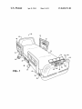
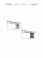
FIG. 1 is a perspective view of a patient handling device
with a mattress;
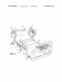
FIG. 2 is a perspective view of the patient handling device
25
inclined position;
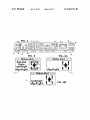
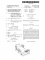
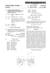
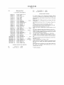
FIG. 3 is a schematic block diagram of the various electri
cal and electronic components of the patient handling device;
30
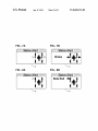
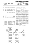
FIG. 5 is a detailed view of a display of the footboard
control panel showing an example of several alarms;
FIGS. 6A and 6B are detailed views of the display of the
35
The angular position of the upper portion 32 with respect to
footboard control panel showing a brake alarm;
the surface 28 is commonly referred to as a “fowler angle” or
FIGS. 8A and 8B are detailed views of the display of the
“fowler position”.
footboard control panel showing a siderail alarm;
40
footboard control panel showing a bed exit alarm;
FIG. 10 is a detailed view of an outside siderail control
panel;
FIG. 11 is a detailed view of an inside siderail control
panel;
45
FIG. 12 is a detailed view of the display of the footboard
control panel showing a menu;
FIG. 13 is a detailed view of the display of the footboard
control panel showing an instructional message;
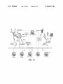
FIG. 14 is a schematic view of a healthcare facility with a
surface 28. This allows the patient to be positioned in a variety
of con?gurations as are well known to those skilled in the art.
FIGS. 7A and 7B are detailed views of the display of the
FIGS. 9A and 9B are detailed views of the display of the
referred to as a “fowler portion” or simply a “fowler”. The
upper and lower portions 32, 34 are angularly adjustable with
respect to the surface 28 between a plurality of angular posi
tions. Said another way, the upper and lower portions 32, 34
may be adjusted such that they are non-parallel with the
annunciator;
footboard control panel showing a low height alarm;
ing systems employed on patient handling devices are well
known in the art and any suitable system may be employed
here, thus the braking system is not described in detail.
Referring to FIG. 2, the frame 22 includes an upper portion
32 and a lower portion 34. The upper portion 32 is often
with the mattress removed to illustrate the upper portion in an
FIG. 4 is a detailed view of a footboard control panel and
device 20 preferably includes a brake for immobilizing at
least one of the wheels 26 and more preferably immobilizing
all of the wheels 26. The brake is applied via a brake pedal 30.
In alternative embodiments, the brake may be applied utilize
a handle, button, or other suitable activation technique. Brak
The frame 22 de?nes two sides 36 running lengthwise with
the arms and legs of a patient lying in the patient handling
device 20 and two ends (not labeled) transverse to the sides
36. A footboard 38 is disposed transverse to the sides 36 and
adjacent to one of the ends. Likewise, a headboard 40 may be
disposed transverse to the sides 36 and adjacent to the other
end of the frame 22. Obviously, the footboard 38 is typically
disposed near the feet of a patient lying on the patient han
dling device 20 while the headboard 40 is disposed near the
head of the patient.
50
network and a patient handling device bay ID system;
The patient handling device 20 also includes at least one
siderail 42 disposed adjacent one of the sides 36 of the frame
22. The siderail 42 is moveable between an up position and a
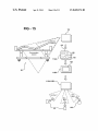
FIG. 15 is a schematic view of alternative room modules in
the patient handling device bay ID system illustrating their
down position. In the up position, the siderail 42 prevents the
communication with the patient handling device and non
patient from accidentally rolling off the patient handling
patient handling device devices; and
55
FIG. 16 is a display representation at a remote computer
illustrating a user interface of the present invention.
device 20 or easily exiting the patient handling device 20. It is
preferred that the siderail 42 include a locking mechanism
(not shown) to lock the siderail 42 in the up position, such that
it may not be easily lowered by the patient. In the preferred
DETAILED DESCRIPTION OF THE INVENTION
embodiment, the at least one siderail is implemented as a
60
Referring to the Figures, wherein like numerals indicate
corresponding parts throughout the several views, a patient
handling device 20 is shown in FIG. 1. Those skilled in the art
realize that the patient handling device 20 of the present
invention may be implemented as a gurney, stretcher, surgical
table, examination table, wheel chair, ambulance cot, or other
suitable device as is known to the art. Furthermore, the patient
65
plurality of siderails, and more preferably as four siderails:
two adjacent the upper portion 32 with one on each side 36 of
the frame 22 and two adjacent the lower portion 34 with one
on each side 36 of the frame 22. In FIGS. 1 and 2, three of the
siderails 42 are shown in the up position and one (not shown)
is in the down position.
Referring now to FIG. 3, the patient handling device 20
includes a controller 44 for controlling operation of the
US 8,689,376 B2
6
5
patient handling device 20 and monitoring various features of
the patient handling device 20. The controller 44 is preferably
a height sensor 60 for sensing the height of the frame 22
with respect to the surface 28.
an upper portion potentiometer 62 for sensing an angular
position of the upper portion 32 with respect to the
a microprocessor-based device, such as a microcontroller.
However, those skilled in the art realize that other suitable
surface 28;
a lower portion potentiometer 64 for sensing an angular
position of the lower portion 34 with respect to the
surface 28;
at least one load cell 66, and preferably four load cells 66,
for sensing the weight, presence, and/ or position of the
patient on the patient handling device 20; and
implementations may be employed for the controller 44. The
patient handling device 20 also includes a variety of electrical
and electronic components (not shown) interfaced with or
integrated into the controller 44 for enabling operation of the
controller 44 and communication with the controller 44.
These components may include, but are not limited to, power
supplies, communication interface circuits, networking cir
an arm/ disarm signal from a bed exit system.
Those skilled in the art will realize numerous techniques for
cuits, ampli?ers, multiplexers, logic gates, resistors, capaci
tors, inductors, and diodes. At least one analog-to-digital
converter 46 (ADC) is electrically connected to the controller
44 to convert analog signals from variable voltage/current
devices to digital signals which are usable by the controller
44. The at least one ADC 46 may be separate (i.e., stand
alone) from the controller 44 and/or integrated within the
controller 44. Furthermore, the patient handling device 20
may also include a plurality of distributed nodes (not shown)
implementing the sensors 54 with the patient handling device
20. For example, in the preferred embodiment, the siderail
switches 56 are implemented as mechanical rocker-type
switches. However, the siderail switches 56 may alternatively
be implemented as inductive or capacitive sensing proximity
switches, photosensitive detectors, etc. Furthermore, those
20
skilled in the art will realize that additional sensors that may
electrically connected to the controller 44 and various elec
be utilized to monitor a feature of the patient handling device
20.
trical/electronic devices as described herein. The distributed
nodes facilitate communication between the devices and the
controller 44 while reducing overall wiring costs and com
handling device 20 and/ or detects a position of the patient on
the patient handling device 20. Such a bed exit system is
The bed exit system detects patient exit from the patient
25
plexity.
described in Us. Pat. No. 5,276,432, which is hereby incor
The patient handling device 20 includes an upper portion
actuator 48 operatively connected to the upper portion 32.
porated by reference. The bed exit system is preferably incor
porated as one or more software routines in the controller 44
The upper portion actuator 48 moves the upper portion 32 to
adjust the upper portion 32 between a plurality of angular
positions. The upper portion actuator 48 is in communication
with the controller 44 to receive control signals from the
controller 44. The upper portion actuator 48 is preferably a
bi-directional motor such that the upper portion actuator 48
can increase and decrease the angular position of the upper
portion 32 with respect to a horizontal surface 28 such as the
30
to track the patient’s center of gravity. By knowing the
patient’s center of gravity, pressure ulcer management can be
performed by knowing that the patient hasn’t moved or
turned. Furthermore, the load cells 66, via the bed exit system,
35
actuator 50 operatively connected to the lower portion 34 for
actuator 50 is electrically connected to the controller 44 and is
preferably a bi-directional motor and operates similarly to the
upper portion actuator 48 described above. The patient han
dling device 20 also includes a lifting mechanism 52 opera
40
45
patient handling device 20. Of course, the footboard control
panel 68 may use different styles of pushbuttons, switches, or
knobs as is well known to those skilled in the art. The foot
50
board control panel 68 also includes a display 74 for display
ing information regarding the patient handling device 20 to a
user (e.g., nurse, doctor, technician, etc.). The display 74 in
the preferred embodiment is a back-lit liquid crystal-type
device, however, other types of displays 74, including touch
patient handling device 20. The actuators 48, 50 and lifting
screen displays 74 for accepting user input, are known to
those skilled in the art. A cover 76 is pivotally hinged to the
footboard 38 adjacent to the footboard control panel 68 for
mechanism 52 are well known to those skilled in the art and
any suitable actuator 48, 50 or lifting mechanism 52 may be
implemented; therefore, the actuators 48, 50 and lifting
communication with the controller 44. In the preferred
embodiment, the patient handling device 20 includes a foot
board control panel 68 disposed in the footboard 38 of the
patient handling device 20. The footboard control panel 68, as
shown in detail in FIG. 4, includes a plurality of membrane
style pushbuttons for controlling various features of the
tively connected to the frame 22 for lifting and lowering the
frame 22 with respect to the surface 28. The lifting mecha
nism 52 is electrically connected to the controller 44 and
preferably includes a bi-directional motor. Of course, those
skilled in the art realize that the patient handling device 20
may include other actuators for operating features of the
may be utilized to predict a bed exit before it occurs.
Referring again to FIG. 1, the patient handling device 20
also preferably includes several control panels 68, 70, 72 in
?oor upon which the patient handling device 20 is supported.
The patient handling device 20 also includes a lower portion
moving the lower portion 34 to adjust the lower portion 34
between a plurality of angular positions. The lower portion
and utilizes the preferred four load cells 66 as described
above. The load cells 66, via the bed exit system, may be used
55
concealing and protecting the footboard control panel 68
mechanism 52 are not described in further detail.
when closed. The cover 76 may include a window (not
A plurality of sensors 54 are supported by the patient
handling device 20 with each sensor 54 being associated with
the various features of the patient handling device 20. Each
shown) to allow viewing of the display 74 when the cover 76
is closed.
sensor 54 senses at least one feature of the patient handling
device 20 and generates a sensor signal corresponding to that
The patient handling device 20 also preferably includes at
60
least one outside siderail control panel 70, shown in detail in
FIG. 10, and at least one inside siderail control panel 72,
shown in detail in FIG. 11. The inside siderail control panel 72
is disposed on the inside (i.e., close to the patient) of at least
65
patient handling device 20 and an interface to other off-bed
feature of the patient handling device 20. These sensors 54
include, but are not limited to:
at least one siderail switch 56 for sensing the position of
each siderail 42, speci?cally, whether each siderail 42 is
in the up position;
a brake sensor 58 for sensing the activation of the brake;
one of the siderails 42 to allow convenient control of the
features (e.g., television control, nurse call, etc.). The outside
siderail control panel 70 is disposed on the outside (i.e., away
US 8,689,376 B2
7
8
from the patient) of at least one of the siderails to allow
state to an undesired state. Of course, the amount of variation
convenient control of the patient handling device 20 by users
other than the patient. The siderail control panels 70, 72
between the current and initial sensor data that results in
triggering the alarm may be adjusted, depending on the nature
of the data. For example, a variation of a few pounds in the
weight of the patient (between initial and current sensor data)
need not trigger the alarm, but a variation of ?fty pounds
preferably include membrane-style pushbuttons, but other
alternatives are known to those skilled in the art.
The patient handling device 20 includes an upper portion
control 78, a lower portion control 80, and a height control 82,
each control electrically connected to the controller 44. Each
of these controls 78, 80, 82 is preferably implemented as a
pair of membrane-style pushbuttons (one for up and one for
down). In the preferred embodiment, the upper and lower
portion controls 78, 80 are disposed on each of the control
panels 68, 70, 72 while the height control 82 is disposed on
the outside siderail control panel 70 and the footboard control
panel 68, i.e., not on the inside siderail control panel 72. The
upper portion control 78 generates an upper portion control
signal, the lower portion control 80 generates a lower portion
control signal, and the height control 82 generates a height
control signal. Each of these control signals is communicated
to the controller 44. The controller 44 typically responds to
could. Furthermore, the step of periodically acquiring the
sensor signals may be described as the controller 44 routinely
examining the sensor signals to determine the current state of
the sensors 54. Alternatively, the step of periodically acquir
ing the sensor signals may be described as being immediately
triggered by a state change, such as, but not limited to, the
presence of an interrupt signal at the controller 44.
Alternative methods to issuing the alarm are contemplated
within the scope of the invention. In one method, the current
sensor data is compared to predetermined data. This prede
termined data may be set by the manufacturer of the patient
handling device 20 or may be set by the user. In an embodi
20
each control signal by controlling the actuator corresponding
to the control signal in the appropriate direction. A patient or
user of the patient handling device 20 can then use the con
trols 78, 80, 82 to selectively adjust the height, upper portion
angular position, and/or lower portion angular position of the
patient handling device 20.
25
The patient handling device 20 includes a user-selectable
control for producing a control signal. In the preferred
embodiment, the user-selectable control is a power button 84,
preferably as part of the footboard control panel 68, as shown
in FIG. 4. However, other controls for producing the control
signal and other locations for the power button 84 are also
instance, the alarm may be conveyed by activating an alert
lamp which produces light. Referring to FIGS. 1 and 2, in the
preferred embodiment, the patient handling device 20
30
acceptable. The power button 84 produces the control signal,
35
One side alert lamp 88 is disposed on one side 36 of the
40
patient handling device 20 while the other side alert lamp 88
is disposed on the other side 36 of the patient handling device
20. The alert lamps 86, 88 are positioned such that the light
produced by the alert lamp is viewable outward from the
patient handling device 20 along at least 180 degrees of a
power button 84 also controls the ?ow of power to the patient
handling device 20. Furthermore, the power button 84 cannot
be activated (i.e., power will not ?ow to the patient handling
device 20) unless the brake has been set to immobilize the
patient handling device 20.
The controller 44 receives the control signal and begins to
circle de?ned around the patient handling device 20 and more
preferably viewable at least 270 degrees of the circle de?ned
by the patient handling device 20. Since the headboard 40 of
initiate the monitoring of the patient handling device 20.
Speci?cally, in response to receiving the control signal, the
controller 44 acquires the sensor signal from each of the
sensors 54 that is to be monitored. The controller 44 generates
initial sensor data based on the initially acquired sensor sig
nals. This initial sensor data then becomes the “setpoint” and
is stored in a memory of the controller 44, thus establishing a
45
50
56, the brake sensor 58, and the load cells 66, then the position
of each siderail 42 and the brake and the weight measured by
color typically has a wavelength in the range of 577 to 597
55
nanometers. Furthermore, it is preferred that the alert lamp
?ash on and off, to emphasize the alarm condition. Those
skilled in the art will realize other locations, con?gurations,
current con?guration of the arm/ disarm signal (e.g., armed or
colors, and wavelengths for the alert lamps 86, 88. The alert
lamps 86, 88 are deactivated, i.e., turned off, when there is no
disarmed) are stored in the memory. Thus, the initial sensor
data is based on the position of the components being moni
tored when the power button 84 is depressed.
After generating the initial sensor data, the controller 44
then will periodically acquire the sensor signal from each of
dling device 20. Furthermore, alert lamps may be positioned
such that light is viewable at any point (i.e., 360 degrees)
around the patient handling device 20.
Preferably, the alert lamps 86, 88 are light emitting diodes
(LEDs) such that replacement of the alert lamps 86, 88 is a
rarity. It is also preferred that the alert lamps 86, 88 produce
an amber (or yellow) colored light. Light having an amber
the load cells 66 are stored in the memory. If the sensors 54 to
be monitored are the four siderail switches 56, the brake
sensor 58, and the arm/disarm signal from the bed exit sys
tem, then the position of each siderail 42 and the brake and the
the patient handling device 20 is traditionally positioned
against a wall, the light produced by the alert lamps 86, 88 is
viewable no matter where a user is aron the patient han
desired state of the patient handling device. For example, if
the sensors 54 to be monitored are the four siderail switches
includes a plurality of alert lamps: at least one footboard alert
lamp 86 and a pair of side alert lamps 88. The footboard alert
lamp 86 is coupled to the footboard 38 and disposed in a
footboard lamp housing 90 located below the footboard con
trol panel 68.
which is sent to the controller 44 to initiate monitoring of the
patient handling device 20. In the preferred embodiment, the
ment in which the predetermined data is set by the user,
con?guration controls are provided as part of the footboard
control panel 68. Those skilled in the art realize that the initial
sensor data may be considered to be the predetermined data
since the initial sensor data is set (i.e., predetermined) by the
user’ s act of turning the patient handling device 20 on via the
power button 84.
The alarm may be conveyed in several forms. In one
60
substantial variation between the current sensor data and the
predetermined data (or initial sensor data).
To deactivate the alarm and the alert lamps 86, 88, a user
the monitored sensors 54 to generate current sensor data. This
may simply correct the problem (e.g., raise a siderail that was
current sensor data is then compared to the initial sensor data.
lowered). Alternatively, deactivating the alert lamps 86, 88
An alarm may be then issued in response to a substantial 65 may be accomplished by simply turning off power to the
variation between the current sensor 54 data and the initial
patient handling device 20 by pressing the power button 84
sensor data. This variation indicates a change from the desired
and then turning power back on, by again pressing the power
US 8,689,376 B2
10
embodiment provides several results. First, the lower portion
button 84. When the patient handling device 20 is restarted,
the initial sensor data will be set to the current (and desired)
actuator 48 is actuated to position the lower portion to a
state.
horizontal position (i.e., parallel with the surface 28). Next,
The patient handling device 20 may also include a normal
lamp 92 which is activated (i.e., illuminated) when there is no
the normal lamp 92 is illuminated when there is no alarm. The
the upper portion actuator 48 is actuated to position the upper
portion 32 outside of a restricted range of angular positions of
the upper portion 32 In the preferred embodiment, this
restricted range is between 0 and 30 degrees with respect to
the surface 28. However, different ranges of angular positions
normal lamp 92 is also preferably disposed within the foot
board lamp housing 90. The normal lamp 92 produces a light
having a wavelength different from the wavelength of the
may also be utilized. For example, in one alternative embodi
ment, the restricted range may be between 0 and 45 degrees.
In another alternative embodiment, the restricted range may
light produced by the alert lamp. Preferably, the normal lamp
be any angular position greater than 45 degrees. If the upper
portion 32 is already positioned outside the restricted range of
angular positions, then no actuation takes place. The control
ler 44 receives feedback (i.e., the current position of the upper
portion 32) from the upper position sensor 54.
Finally, activation of the position lock control 1 06 results in
preventing the operation of the upper portion actuator 48
utilizing the upper portion control 78 into the restricted range
substantial variation between the current sensor data and the
predetermined data (or initial sensor data). Said another way,
92 is at least one LED that produces a green colored light.
Those skilled in the art realize that green color light has a
wavelength in the range of 492 to 577 nanometers. The nor
mal lamp 92 is deactivated, i.e., turned off, when there is a
substantial variation between the current sensor data and the
predetermined data (or initial sensor data), i.e., when the
patient handling device 20 is in the undesired state.
Thus, in the preferred embodiment, it is easy for a user
20
(e.g., nurse, doctor, orderly, etc.) to quickly determine if there
is a problem with the patient handling device 20 that needs to
be addressed. The user need simply notice whether the patient
handling device 20 is producing a green light or a ?ashing
amber light.
tion control 78. This allows a simple and convenient tech
nique for a user to place the patient in an inclined position and
25
keep the patient in that position. In some embodiments, how
ever, even when the position lock control 106 is actuated, the
upper portion 32 can be adjusted through a plurality of per
mitted angular positions that fall outside the restricted range
of angular positions, such as those positions above 30 degrees
In another instance, the alarm may be conveyed to a user by
sounding an audible signal. The patient handling device 20
may include a speaker 94 in communication with the control
ler 44 for sounding this audible signal.
In yet another instance, the alarm may be conveyed by
of angular positions. Thus, in the preferred embodiment, the
patient (or otheruser) is not able to lower the upper portion 32
under 30 degrees utilizing the pushbuttons of the upper por
30
with respect to the surface 28. Those skilled in the art realize
transmitting alarm data to a remote computer 95, external
that certain medical conditions necessitate positioning
from the patient handling device 20. The controller 44 of the
patients in these permitted positions for extended periods of
patient handling device 20 is in communication with a net
time. Those skilled in the art realize other restricted range of
work interface 96. The network interface 96 may then com
municate the alarm data (as well as other data) to the remote
computer 95 over a network 97. Those skilled in the art realize
that the network 97 may be a hardwired network (e. g., Eth
35
are related to the commonly known Trendelenberg position
(where the patient’ s feet are disposed higher than their head)
and the knee gatch position. Of course, if CPR is to be initi
ernet) or a wireless network (e.g., WiFi., cellular telephone,
GSM, Bluetooth, etc.).
The alarm my also be conveyed by transmitting a nurse call
ated, a CPR button allows immediate movement of the upper
40
known to those skilled in the art, but typically lack function
ality for detailed data handling. Rather, nurse call systems
typically provide a simple on/off signal to alert the user (e.g.,
45
The patient handling device 20 of the present invention also
of angular positions of other portions of the patient handling
device 20, such as, but not limited to, the lower portion 34.
The patient handling device 20 also includes an annuncia
tor 110 for quickly alerting the user to status conditions of the
provides functionality for limiting (or locking out) operation
of the patient handling device 20. The footboard control panel
68 includes an upper portion lockout control 98, a lower
portion lockout control 100, a height lockout control 102, and
and lower portions of the bed to a fully horizontal position.
In the preferred embodiment described above, the position
lock control 106 restricted the range of angular positions of
the upper portion 32. In other embodiments, however, the
position lock control 106 may alternatively restrict the range
signal to a nurse call system. Nurse call systems are well
a nurse) to a problem.
angular positions that have clinical or operational signi?
cance. Two examples of restricted ranges of angular positions
50
patient handling device 20. The annunciator 110 is preferably
located adjacent to and below the footboard control panel 68,
however other locations may also be acceptable. The annun
a motion lockout control 104. Each of these lockout controls
98, 100, 102, 104 is electrically connected to the controller 44
ciator 110 includes annunciator lamps (not shown) electri
and sends a corresponding lockout control signal to the con
troller 44 when activated. For example, when the lower por
cally connected to the controller 44. A cover plate is af?xed
tion lockout control 98 is activated, the lower portion actuator
over the annunciator lamps, such that messages are illumi
55
50 will not function when the lower portion controls 80 on the
siderails 42 and/or the footboard control panel 68 are
not limited to:
Motion Lockout Set
Siderail Lockout Set
depressed. The same reasoning extends to the upper portion
lockout control 100, the height lockout control 102, and the
motion lockout control 104.
Low Height
60
The patient handling device 20 of the present invention also
the controller 44. The position lock control 106 generates a
Brake Set
Bed Exit Alarm
Zero Weight Alarm
provides a position lock control 106. The position lock con
trol 106 is preferably a membrane-style pushbutton located in
the footboard control panel 68 and electrically connected to
position lock signal which is received by the controller 44.
The activation of the position lock control 106 in the preferred
nated when appropriate. These messages may include, but are
Siderail Alarm
Power On
65
One advantageous feature of the annunciator 110 is that it
remains visible to the user, even when the cover 76 of the
footboard control panel 68 is closed.
US 8,689,376 B2
11
12
The display 74 of the footboard control panel 68 is used as
network 97. This data may include, but is not limited to, any
an interface between a user of the patient handling device 20
data collected by the controller 44 of the patient handling
device 20, alarm data, location ID data, and non-bed device
and the controller 44. As shown in FIG. 4, the display may
provide information to the user, such as the upper portion
data from non-bed devices 122 in communication with the
angular position and the lower portion angular position.
patient handling device 20. This data may also be utilized by
Referring to FIG. 5, the display 74 may provide a graphical
other systems present on the network 97. For instance, the
data may be automatically transmitted to an electronic medi
cal record system 99. Furthermore, the controller 44 of the
patient handling device 20 may receive commands initiated at
the remote computer 95.
Referring to FIG. 16, one possible con?guration of a dis
play 124 at the remote computer 95 is shown. As shown, the
representation and/ or a schematic map of the patient handling
device 20 to indicate which component is triggering an alarm.
The triggering component may be blinking or otherwise indi
cated as is known to those skilled in the art. For example,
FIGS. 6A and 6B will alternate on the display 74, creating a
blinking effect to inform the user that the height of the patient
handling device 20 is low (i.e., lower than the desired state).
remote computer 95 includes a touch-sensitive user interface
FIGS. 7A and 7B will alternate on the display 74 to show the
user that the brake is no longer set. Likewise, FIGS. 8A and
8B show that one of the siderails 42 is out of position and
FIGS. 9A and 9B indicate that a bed exit alarm is tripped.
As shown in FIG. 12, the display may provide a menu from
which the user can con?gure features of the patient handling
device, by utiliZing user interface controls 108 located on the
footboard control panel 68. The display 74 can also convey
(not labeled) that allows hospital personnel such as a nurse to
not only view the patient handling device data transmitted to
the network 97 from the patient handling device 20, but also
remotely activate features of the patient handling device 20
such as a scale, the bed exit system, brakes, articulation locks,
20
and the like. The user interface may also include con?gura
tion controls to allow the users to set the desired state of the
patient handling device 20.
non-alarm messages to the user, such as in FIG. 13, instruct
ing the user not to touch the bed (e.g., while the patient is
As shown in FIG. 16, the user interface also includes a bed
weighed).
con?guration interface 180. This interface 180 includes mul
Referring now to FIG. 14, the patient handling device 20 of
25 tiple buttons 182 that allow a user such as a nurse to establish
the present invention may be a part of a location detection
the “desired” con?guration of the bed or patient handling
device 20 by setting the conditions to be monitored. As each
of the buttons 182 are selected, various options are provided
system (not labeled). The location detection system locates
patient handling devices 20 in a facility such as a hospital.
Such a location detection system is described in Us. patent
application Ser. No. ll/277,838, ?led on Mar. 29, 2006,
to the user to establish the “desired” bed con?guration. For
30
which is hereby incorporated by reference.
The location detection system includes a locator 112
mounted at each bay location in each room of the hospital.
The locator 112 is programmed with a location ID to transmit
to the patient handling device 20 once the patient handling
device 20 has “docked” with the locator 112. The locator 112
could be mounted on the ceiling, wall, ?oor, or any location
that permits the locator 112 to carry out its intended function.
Referring to FIG. 15, the locator 112 could also include
additional features to provide an intelligent room module
112A. For instance, the intelligent room module 112A may
include interface buttons 118 for operator selection that cor
35
When the bed height button is selected, the user may be able
40
to de?ne a range of bed heights as being within a “desired”
state, or the user may elect not to monitor bed height. The
fowler angle can also be similarly monitored using the fowler
angle button. Other bed conditions may be monitored based
respond to the patient handling device 20 or room being clean,
dirty, empty, occupied, ready for occupancy, etc. An altema
tive intelligent room module 112B may also include a graphic
display 120 such as a touch-screen display with multiple
example, when the brakes button is selected, the user may
have the option to add or delete brake monitoring as a moni
tored bed condition, or the user may elect “brakes on” as a
“desired” state. When the side rails button is selected, the user
may be able to select which, if any, side rails are included as
monitored bed conditions and whether the “desired” state is
up, down, or an intermediate position. When the bed exit
button is selected, the user may de?ne whether bed exit is to
be monitored, and whether bed exit armed is a “desired” state.
on the speci?c needs of the user or facility in which the bed is
45
located. Lastly, prede?ned “desired” bed con?gurations may
also be stored on the hospital network 97 or in the bed net
nested user screens to access or transmit patient data, patient
handling device data, or room data. The intelligent room
work. These prede?ned “desired” bed con?gurations may be
module 112A, 112B may transmit this information, e.g.,
clean/dirty, etc., directly or indirectly to the hospital network
97 using wired and/or wireless communication paths. Com
based on events such as surgery, or clinical conditions of the
selectable at the bed con?guration interface 180 and may be
50
induced pneumonia (VIP), as described further below.
The bed status monitored can also be armed with an acti
vation button on the footboard. This embodiment allows for
the nurse or other clinician to con?gure the bed physically, as
munication can occur from the intelligent room modules
112A, 112B directly to the hospital network 97, from the
intelligent room modules 112A, 112B to other patient han
dling devices and then to the hospital network 97 or to more
patient such as when a ventilator is in use to prevent ventilator
55
they normally would, and then identify this as the desired
than one available hospital network, or directly from the
intelligent room modules 112A, 112B to the computer 95 or
state by activating the monitoring system.
to more than one computer 95. The intelligent room modules
indicators activated in the same manner as the alert and nor
The display 124 may also include amber 126 and green 128
mal lamps 86, 92 on the patient handling device 20. Audible
112A, 112B may also be con?gured as access points between
the patient handling devices 20 and multiple non-bed devices
122 such as patient monitoring devices, patient treatment
devices, diagnostic devices, and the like, or the intelligent
60
other locations to indicate whether the patient handling
device 20 is in a desired or undesirable state or con?guration.
The remote computer 95 may be in communication with a
room modules 112A, 112B may be con?gured as access
points between the hospital network 12 and the non-bed
devices 122.
As stated above, data may be transmitted to the remote
computer 95 from the patient handling device 20 via the
alarms may also be provided at the remote computer 95 or
portable device (e.g., cellular phones, PDAs, pagers, etc.) to
65
deliver information about one or more patient handling
devices 20 to a user. This information may include not only
that an alarm has occurred, but the exact nature of the alarm.
US 8,689,376 B2
14
13
For instance, the portable device may display data similar to
that displayed on the display 74 of the footboard control panel
and providing a uni?ed indication that said bed is in a
68.
their desired state or providing an indication that said
bed is in an undesired con?guration when at least one of
said conditions deviates from its desired state.
desired con?guration when each of said conditions is in
Obviously, many modi?cations and variations of the
present invention are possible in light of the above teachings.
The invention may be practiced otherwise than as speci?cally
described within the scope of the appended claims.
What is claimed is:
9. The bed of claim 8, wherein said uni?ed indication
comprises a lamp in communication with said controller, said
controller illuminating said lamp to provide said uni?ed indi
1. A bed comprising:
cation that said bed is in a desired con?guration.
a frame for supporting a patient;
a plurality of side rails movable between raised and low
10. The bed of claim 9, further including another lamp in
communication with said controller, said controller adapted
ered positions;
to cause a change in an illumination state of said other lamp
when said controller provides said indication that that said
bed is in said undesired desired con?guration.
11. The bed of claim 9, wherein said lamp produces a green
colored light when illuminated to provide said uni?ed indi
cation that said bed is in a desired con?guration.
12. The bed of claim 8, wherein said uni?ed indicator
comprises a lamp, said controller illuminating said lamp to
a plurality of wheels adapted to support said frame;
a brake for immobiliZing at least one of said plurality of
wheels;
a lifting mechanism adapted to raise and lower said frame;
a bed exit system adapted to detect when a patient has
exited the bed; and
a controller with a monitoring system in communication
with said brake, said bed exit system, and said plurality
20
provide an indication that that said bed is in an undesired
of side rails, said monitoring system monitoring said
desired con?guration.
brake, said side rails, and said bed exit system, and said
controller determining whether each of said brake, said
13. The bed of claim 12, further including another lamp in
communication with said controller, said controller adapted
side rails, and said bed exit system is in a desired state so
that the bed is in a desired con?guration or whether any
to cause a change in an illumination state of said other lamp
25
of said brake, said side rails, and said bed exit system
deviates from their desired state so that the bed is in an
undesired con?guration, and said controller generating a
uni?ed indication when said bed is in said desired con
?guration and generating another indication when said
bed is in said undesired con?guration.
2. The bed of claim 1 wherein said controller is further
30
when said controller provides said indication that that said
bed is in said undesired desired con?guration.
14. The bed of claim 12, wherein said lamp produces a
yellow or amber colored light when illuminated to provide
said indication that said bed is in an undesired con?guration.
15. The bed of claim 8, further comprising a bed exit
system, wherein one of said conditions comprises a bed occu
pancy condition detected by said bed exit system.
adapted to allow a user to select if said bed exit system is to be
16. The bed of claim 15, further comprising a user input
monitored, wherein if said bed exit system is monitored said
device to allow a user to select if said bed exit system is to be
controller will generate said other indication or a third indi
35
cation when said bed exit system is disarmed.
3. The bed of claim 1 wherein said uni?ed indication com
prises a lamp, wherein said controller causes a change in
illumination state of said lamp when at least one of said brake,
said lifting mechanism, and said side rails are changed to an
40
undesired state.
4. The bed of claim 1 wherein said uni?ed indication com
prises a lamp, wherein said frame further includes an upper
portion and a lower portion, said upper portion adapted to be
angularly adjustable; and wherein said controller is further
45
adapted to allow a user to select if an angle of said upper
portion is to be monitored, said controller causing a change in
illumination state of said if said angle is monitored and if said
angle changes to an undesired state.
5. The bed of claim 3 wherein said lamp is positioned
50
beneath a foot end of said bed and spaced from said control
panel, said bed including no indicia adjacent said lamp indi
cating a condition associated with said lamp.
6. The bed of claim 3 said lamp comprising a ?rst lamp,
further including a second lamp in communication with said
monitored.
17. The bed of claim 15, wherein said user input actuates
said bed exit system, when said bed exit system is activated
said controller monitors said bed exit system and when said
bed exit system is not activated said controller does not moni
tor said bed exit system.
18. The bed of claim 9, wherein said lamp is positioned at
a foot end of said bed and is viewable by a caregiver spaced
from the foot end of the bed.
19. The bed of claim 8, further comprising a side rail
movable between raised and lowered positions, wherein one
of said conditions comprises whether said rail is moved.
20. The bed of claim 8, further comprising a plurality of
wheels adapted to support said patient support and a brake for
immobiliZing at least one of said plurality of wheels, wherein
one of said conditions comprises whether brake is actuated.
21. The bed of claim 8, further comprising a deck with a
?rst portion and a second portion, said ?rst portion adapted to
be angularly adjustable; and
wherein one of said conditions comprises said angle of said
55
?rst portion.
controller, said controller adapted to cause a change in an
22. The bed of claim 8, wherein said controller is adapted
illumination state of said second lamp when said controller
causes a change in the illumination state of said ?rst lamp.
7. The bed of claim 6 wherein said ?rst lamp and said
second lamp are both positioned at a foot end of said bed.
to acquire the sensor signal from each of the sensors that is to
be monitored and generate initial sensor data based on the
initially acquired sensor signals.
60
23. The bed of claim 22, wherein said initial sensor data is
8. A bed comprising:
a patient support for supporting a patient;
stored as a setpoint in a memory device.
a plurality of sensors for generating a plurality of sensor
signals, said sensors associated with a set of conditions
comprises a memory device of controller or a network.
associated with said bed for being monitored; and
a controller in communication with said sensors for moni
toring whether said set of conditions is in a desired state
24. The bed of claim 23, wherein said memory device
65
25. The bed of claim 22, wherein said conditions comprise
conditions of components of said bed, and said initial sensor
data is based on the position of the components being moni
tored when a user actuates a user input device.
US 8,689,376 B2
15
16
26. The bed of claim 22, wherein said controller periodi
cally acquires the sensor signal from each of the monitored
sensors to generate current sensor data and compares the
current sensor data to the initial sensor data and generates said
indication that said bed
is in an undesired desired con?guration in response to a
substantial variation between the current sensor data and the
initial sensor data.
27. The bed of claim 26, wherein the amount of variation
between the current and initial sensor data that results in said
indication that that said bed is in an undesired desired con
?guration may be adjusted.
*
*
*
*
*