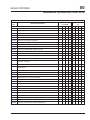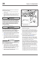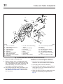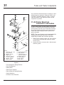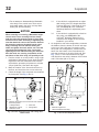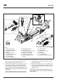
1
COLUMBIA MAINTENANCE MANUAL
Models: CL112
CL120
STI-409-2 (2/10P)
Published by
Daimler Trucks North America LLC
4747 N. Channel Ave.
Portland, OR 97217
Printed in U.S.A.
Foreword
Scheduled maintenance provides a key element for the safe operation of your vehicle. A proper
maintenance program also helps to minimize downtime and to safeguard warranties. This
maintenance manual provides information necessary for years of safe, reliable, and cost-efficient
vehicle operation.
IMPORTANT: The maintenance operations in this manual are not all-inclusive. Also
refer to other component and body manufacturers’ instructions for specific inspection
and maintenance instructions.
Perform the operations in this maintenance manual at scheduled intervals. Perform the pretrip
and post-trip inspections, and daily/weekly/monthly maintenance, as outlined in the vehicle
driver’s manual. Major components, such as engines, transmissions, and rear axles, are covered
in their own maintenance and operation manuals, that are provided with the vehicle. Perform any
maintenance operations listed at the intervals scheduled in those manuals. Your Freightliner
Dealership has the qualified technicians and equipment to perform this maintenance for you.
They can also set up a scheduled maintenance program tailored specifically to your needs.
Optionally, they can assist you in learning how to perform these maintenance procedures.
IMPORTANT: Descriptions and specifications in this manual were in effect at the time of
printing. Freightliner Trucks reserves the right to discontinue models and to change
specifications or design at any time without notice and without incurring obligation.
Descriptions and specifications contained in this publication provide no warranty,
expressed or implied, and are subject to revision and editions without notice.
Refer to www.Daimler-TrucksNorthAmerica.com and www.FreightlinerTrucks.com for more
information, or contact Daimler Trucks North America LLC at the address below.
Environmental Concerns and Recommendations
Whenever you see instructions in this manual to discard materials, you should attempt to reclaim
and recycle them. To preserve our environment, follow appropriate environmental rules and
regulations when disposing of materials.
NOTICE: Parts Replacement Considerations
Do not replace suspension, axle, or steering parts (such as springs, wheels, hubs, and steering
gears) with used parts. Used parts may have been subjected to collisions or improper use and
have undetected structural damage.
© 2001–2010 Daimler Trucks North America LLC
All rights reserved. No part of this publication, in whole or in part, may be translated, reproduced,
stored in a retrieval system, or transmitted in any form by any means, electronic, mechanical,
photocopying, recording, or otherwise, without the prior written permission of Daimler Trucks
North America LLC. Daimler Trucks North America LLC is a Daimler company.
Daimler Trucks North America LLC
Service Systems and Documentation (POC-SSD)
P.O. Box 3849
Portland, OR 97208–3849
Introduction
Descriptions of Service Publications
Daimler Trucks North America LLC distributes the following major service publications in paper and electronic
(via ServicePro®) formats.
Workshop/Service
Manual
Workshop/service manuals contain service and repair information for all vehicle
systems and components, except for major components such as engines, transmissions, and rear axles. Each workshop/service manual section is divided into
subjects that can include general information, principles of operation, removal,
disassembly, assembly, installation, and specifications.
Maintenance Manual
Maintenance manuals contain routine maintenance procedures and intervals for
vehicle components and systems. They have information such as lubrication
procedures and tables, fluid replacement procedures, fluid capacities, specifications, and procedures for adjustments and for checking the tightness of fasteners. Maintenance manuals do not contain detailed repair or service information.
Driver’s/Operator’s
Manual
Driver’s/operator’s manuals contain information needed to enhance the driver’s
understanding of how to operate and care for the vehicle and its components.
Each manual contains a chapter that covers pretrip and post-trip inspections,
and daily, weekly, and monthly maintenance of vehicle components.
Driver’s/operator’s manuals do not contain detailed repair or service information.
Service Bulletins
Service bulletins provide the latest service tips, field repairs, product improvements, and related information. Some service bulletins are updates to information in the workshop/service manual. These bulletins take precedence over
workshop/service manual information, until the latter is updated; at that time, the
bulletin is usually canceled. The service bulletins manual is available only to
dealers. When doing service work on a vehicle system or part, check for a valid
service bulletin for the latest information on the subject.
IMPORTANT: Before using a particular service bulletin, check the current
service bulletin validity list to be sure the bulletin is valid.
Parts Technical Bulletins
Parts technical bulletins provide information on parts. These bulletins contain
lists of parts and BOMs needed to do replacement and upgrade procedures.
Web-based repair, service, and parts documentation can be accessed using the following applications on the
AccessFreightliner.com website.
ServicePro
ServicePro® provides Web-based access to the most up-to-date versions of the
publications listed above. In addition, the Service Solutions feature provides diagnostic assistance with Symptoms Search, by connecting to a large knowledge
base gathered from technicians and service personnel. Search results for both
documents and service solutions can be narrowed by initially entering vehicle
identification data.
PartsPro
PartsPro® is an electronic parts catalog system, showing the specified vehicle’s
build record.
EZWiring
EZWiring™ makes Freightliner, Sterling, Western Star, Thomas Built Buses, and
Freightliner Custom Chassis Corporation products’ wiring drawings and floating
pin lists available online for viewing and printing. EZWiring can also be accessed from within PartsPro.
Columbia Maintenance Manual, February 2010
I–1
Introduction
Descriptions of Service Publications
Warranty-related service information available on the AccessFreightliner.com website includes the following
documentation.
Recall Campaigns
Recall campaigns cover situations that involve service work or replacement of
parts in connection with a recall notice. These campaigns pertain to matters of
vehicle safety. All recall campaigns are distributed to dealers; customers receive
notices that apply to their vehicles.
Field Service Campaigns
Field service campaigns are concerned with non-safety-related service work or
replacement of parts. All field service campaigns are distributed to dealers; customers receive notices that apply to their vehicles.
I–2
Columbia Maintenance Manual, February 2010
Introduction
Page Description
For an example of a Columbia Maintenance Manual page, see Fig. 1.
A
B
C
20
Cooling
20−01 Coolant Replacement
20−02 Cooling Fan Inspection
Columbia Maintenance Manual, December 2001
D
E
11/28/2001
A.
B.
C.
D.
E.
f020127
Maintenance Operation Number consists of the Group Number followed by the Sequence Number
Group Title
Group Number
Release Date
Group Number/Page Number
Fig. 1, Example of a Columbia Maintenance Manual Page
Columbia Maintenance Manual, February 2010
I–3
Introduction
Maintenance Manual Contents
Group No.
Group Title
00 . . . . . . . . . . . . . . . . . . . . . . General Information
01 . . . . . . . . . . . . . . . . . . . . . . . . . . . . . . . . Engine
09 . . . . . . . . . . . . . . . . . . . . . . . . . . . . . . Air Intake
13 . . . . . . . . . . . . . . . . . . . . . . . . . Air Compressor
15 . . . . . . . . . . . . . . . . . . . Alternators and Starters
20 . . . . . . . . . . . . . . . . . . . Engine Cooling/Radiator
25 . . . . . . . . . . . . . . . . . . . . . . . . . . . . . . . . Clutch
26 . . . . . . . . . . . . . . . . . . . . . . . . . . . Transmission
31 . . . . . . . . . . . . . Frame and Frame Components
32 . . . . . . . . . . . . . . . . . . . . . . . . . . . . Suspension
33 . . . . . . . . . . . . . . . . . . . . . . . . . . . . . Front Axle
35 . . . . . . . . . . . . . . . . . . . . . . . . . . . . . Rear Axle
40 . . . . . . . . . . . . . . . . . . . . . . . . Wheels and Tires
41 . . . . . . . . . . . . . . . . . . . . . . . . . . . . . . Driveline
42 . . . . . . . . . . . . . . . . . . . . . . . . . . . . . . . . Brakes
46 . . . . . . . . . . . . . . . . . . . . . . . . . . . . . . . Steering
47 . . . . . . . . . . . . . . . . . . . . . . . . . . . . . . . . . Fuel
49 . . . . . . . . . . . . . . . . . . . . . . . . . . . . . . . Exhaust
72 . . . . . . . . . . . . . . . . . . . . . . . . . . . . . . . . Doors
83 . . . . . . . . . . . . . . . . . Heater and Air Conditioner
I–4
Columbia Maintenance Manual, February 2010
General Information
00
Index, Alphabetical
Title of Maintenance Operation (MOP)
MOP Number
Determining Scheduled Maintenance Intervals. . . . . . . . . . . . . . . . . . . . . . . . . . . . . . . . . . . . . . . . . . . . . 00–01
Initial Maintenance (IM) Operations. . . . . . . . . . . . . . . . . . . . . . . . . . . . . . . . . . . . . . . . . . . . . . . . . . . . . 00–05
Lubrication and Fluid Level Check . . . . . . . . . . . . . . . . . . . . . . . . . . . . . . . . . . . . . . . . . . . . . . . . . . . . . 00–04
M1 Maintenance Interval Operations. . . . . . . . . . . . . . . . . . . . . . . . . . . . . . . . . . . . . . . . . . . . . . . . . . . . 00–06
M2 Maintenance Interval Operations. . . . . . . . . . . . . . . . . . . . . . . . . . . . . . . . . . . . . . . . . . . . . . . . . . . . 00–07
M3 Maintenance Interval Operations. . . . . . . . . . . . . . . . . . . . . . . . . . . . . . . . . . . . . . . . . . . . . . . . . . . . 00–08
Maintenance Operation Sets Table . . . . . . . . . . . . . . . . . . . . . . . . . . . . . . . . . . . . . . . . . . . . . . . . . . . . . 00–09
Metric/U.S. Customary Conversion Tables. . . . . . . . . . . . . . . . . . . . . . . . . . . . . . . . . . . . . . . . . . . . . . . . 00–12
Noise Emission Controls Maintenance. . . . . . . . . . . . . . . . . . . . . . . . . . . . . . . . . . . . . . . . . . . . . . . . . . . 00–10
Service Schedule Table . . . . . . . . . . . . . . . . . . . . . . . . . . . . . . . . . . . . . . . . . . . . . . . . . . . . . . . . . . . . . 00–02
Torque Specifications Tables. . . . . . . . . . . . . . . . . . . . . . . . . . . . . . . . . . . . . . . . . . . . . . . . . . . . . . . . . . 00–13
Vehicle Maintenance Schedule Tables. . . . . . . . . . . . . . . . . . . . . . . . . . . . . . . . . . . . . . . . . . . . . . . . . . . 00–03
Verification of Inspections Log. . . . . . . . . . . . . . . . . . . . . . . . . . . . . . . . . . . . . . . . . . . . . . . . . . . . . . . . . 00–11
Columbia Maintenance Manual, February 2010
00
General Information
Determining Scheduled Maintenance Intervals: 00–01
Determining Scheduled
Maintenance Intervals
Performing regular maintenance on your Freightliner
will help ensure that your Freightliner delivers safe
reliable service and optimum performance for years
to come. Failure to follow a regular maintenance program can result in inefficient operation and unscheduled down time.
To determine the correct maintenance intervals for
your vehicle you must first determine the type of service or conditions the vehicle will be operating in.
Generally, most vehicles operate under conditions
that fall within one of the four types of service described. Before placing your new vehicle in service,
determine the type of service (Service Schedule I, II,
III, or IV) that applies to the intended use of the vehicle. After determining the vehicle’s type of service,
refer to the service schedule table or the vehicle
maintenance schedule table, to determine how often
maintenance should be performed.
When the vehicle reaches the distance given for a
maintenance interval, see the Maintenance Interval
Operation Table for a list of the maintenance operations to be performed at that maintenance interval.
Use the maintenance operation reference numbers to
find detailed instructions in the manual on each operation.
Types of Service
Service Schedule I (severe service) applies to vehicles that annually travel less than 6000 miles (10
000 kilometers) or that operate under severe conditions. Examples of severe service, Schedule I usage
include: operation on extremely poor roads or where
there is heavy dust accumulation; constant exposure
to extreme hot, cold, salt-air, or other extreme climates; frequent short-distance travel; constructionsite operation; city operation (fire truck); or farm
operation.
(100 000 kilometers) with minimal city or stop-and-go
operation. Examples of Schedule III usage are: regional delivery that is mostly freeway miles; interstate
transport; or any road operation with high annual
mileage.
Service Schedule IV (long haul transport for Optimized Vehicle Configuration) is for vehicles that annually travel over 60,000 miles (100 000 km) and
meet the following qualifications:
• Meritor 15-1/2 inch dampened/ceramic Lite
Pedal LTD clutch with sealed release bearing.
• Synthetic transmission fluid used in transmission.
• Meritor FF–961 or FF–981 front axle (12,000 lb.
capacity) with synthetic lubricant.
• Front suspension with maintenance-free rubber
bushings for 12,000 lb. capacity suspension.
• Meritor RPL series, or Dana Spicer SPL series
driveline U-joints.
• Synthetic lubricant used in rear axle.
• Equipped with any Freightliner AirLiner suspension.
• Equipped with Meritor Q-Plus extended-lube
cam brakes and automatic slack adjusters, front
and rear.
• Standard brake system package including Bendix AD-9 air dryer—mounted on the right-hand
frame rail, located directly behind the front
bumper—with heater, and a Bendix air compressor.
• TRW TAS65 power steering.
NOTE: Maintenance instructions in this manual
are based on average vehicle use and normal
operating conditions. Unusual vehicle operating
conditions may require service at more frequent
intervals.
Service Schedule II (short-haul transport) applies to
vehicles that annually travel less than 60,000 miles
(100 000 kilometers) and operate under normal conditions. Examples of Schedule II usage are: operation primarily in cities and densely populated areas;
local transport with infrequent freeway travel; or high
percentage of stop-and-go travel.
Service Schedule III (long-haul transport) is for vehicles that annually travel more than 60,000 miles
Columbia Maintenance Manual, February 2010
00/1
00
General Information
Service Schedule Table: 00–02
Service Schedule
Schedule I*
(Severe Service)
vehicles that annually travel less
than 6000 miles (10 000 km)
Schedule II†
(Short-Haul Transport)
vehicles that annually travel less
than 60,000 miles (100 000 km)
Schedule III†
(Long-Haul Transport)
vehicles that annually travel over
60,000 miles (100 000 km)
Schedule IV†
(Long-Haul Transport for
Optimized Vehicle Configuration)
vehicles that annually travel over
60,000 miles (100 000 km)
Maintenance Interval Operation
Maintenance Interval
Frequency
Miles
km
Hours
Initial Maintenance (IM)
first
1000
1600
50
Maintenance 1 (M1)
every
1000
1600
50
Maintenance 2 (M2)
every
5000
8000
500
Maintenance 3 (M3)
every
15,000
24 000
1500
Initial Maintenance (IM)
first
10,000
16 000
Maintenance 1 (M1)
every
10,000
16 000
Maintenance 2 (M2)
every
50,000
80 000
Maintenance 3 (M3)
every
150,000
240 000
Initial Maintenance (IM)
first
25,000
40 000
Maintenance 1 (M1)
every
25,000
40 000
Maintenance 2 (M2)
every
100,000
161 000
Maintenance 3 (M3)
every
300,000
483 000
Initial Maintenance (IM)
first
25,000
40 000
Maintenance 1 (M1)
every
25,000
40 000
Maintenance 2 (M2)
every
100,000
161 000
Maintenance 3 (M3)
every
300,000
483 000
—
—
—
* For Schedule I (severe service) vehicles equipped with an hourmeter, use maintenance intervals based on hours of operation rather than distance traveled.
† Use Schedule I (severe service) maintenance intervals for vehicles that operate under severe conditions, such as extremely poor roads, heavy dust accumu-
lation, extreme climate, frequent short distance travel, construction-site operation, city operation (garbage truck), or farm operation.
Table 1, Service Schedule
00/2
Columbia Maintenance Manual, February 2010
00
General Information
Vehicle Maintenance Schedule Tables: 00–03
1st through 30th Maintenance for Service Schedules I and II
Maint. No.
Maintenance
Interval
1st
IM and M1
Service
Date
Service Schedule I
Service Schedule II
Miles
km
Hours
Miles
km
1000
1600
100
10,000
16 000
2nd
M1
2000
3200
200
20,000
32 000
3rd
M1
3000
4800
300
30,000
48 000
4th
M1
4000
6400
400
40,000
64 000
5th
M1 and M2
5000
8000
500
50,000
80 000
6th
M1
6000
9600
600
60,000
96 000
7th
M1
7000
11 200
700
70,000
112 000
8th
M1
8000
12 800
800
80,000
128 000
9th
M1
9000
14 400
900
90,000
144 000
10th
M1 and M2
10,000
16 000
1000
100,000
160 000
11th
M1
11,000
17 600
1100
110,000
176 000
12th
M1
12,000
19 200
1200
120,000
192 000
13th
M1
13,000
20 800
1300
130,000
208 000
14th
M1
14,000
22 400
1400
140,000
224 000
15th
M1, M2, and M3
15,000
24 000
1500
150,000
240 000
16th
M1
16,000
25 600
1600
160,000
256 000
17th
M1
17,000
27 200
1700
170,000
272 000
18th
M1
18,000
28 800
1800
180,000
288 000
19th
M1
19,000
30 400
1900
190,000
304 000
20th
M1 and M2
20,000
32 000
2000
200,000
320 000
21st
M1
21,000
33 600
2100
210,000
336 000
22nd
M1
22,000
35 200
2200
220,000
352 000
23rd
M1
23,000
36 800
2300
230,000
368 000
24th
M1
24,000
38 400
2400
240,000
384 000
25th
M1 and M2
25,000
40 000
2500
250,000
400 000
26th
M1
26,000
41 600
2600
260,000
416 000
27th
M1
27,000
43 200
2700
270,000
432 000
28th
M1
28,000
44 800
2800
280,000
448 000
29th
M1
29,000
46 400
2900
290,000
464 000
30th
M1, M2, and M3
30,000
48 000
3000
300,000
480 000
Table 2, 1st through 30th Maintenance for Service Schedules I and II
Columbia Maintenance Manual, February 2010
00/3
00
General Information
Vehicle Maintenance Schedule Tables: 00–03
31st through 60th Maintenance for Service Schedules I and II
Maint. No.
Maintenance
Interval
31st
M1
Service
Date
Service Schedule I
Service Schedule II
Miles
km
Hours
Miles
km
31,000
49 600
3100
310,000
496 000
32nd
M1
32,000
51 200
3200
320,000
512 000
33rd
M1
33,000
52 800
3300
330,000
528 000
34th
M1
34,000
54 400
3400
340,000
544 000
35th
M1 and M2
35,000
56 000
3500
350,000
560 000
36th
M1
36,000
57 600
3600
360,000
576 000
37th
M1
37,000
59 200
3700
370,000
592 000
38th
M1
38,000
60 800
3800
380,000
608 000
39th
M1
39,000
62 400
3900
390,000
624 000
40th
M1 and M2
40,000
64 000
4000
400,000
640 000
41st
M1
41,000
65 600
4100
410,000
656 000
42nd
M1
42,000
67 200
4200
420,000
672 000
43rd
M1
43,000
68 800
4300
430,000
688 000
44th
M1
44,000
70 400
4400
440,000
704 000
45th
M1, M2, and M3
45,000
72 000
4500
450,000
720 000
46th
M1
46,000
73 600
4600
460,000
736 000
47th
M1
47,000
75 200
4700
470,000
752 000
48th
M1
48,000
76 800
4800
480,000
768 000
49th
M1
49,000
78 400
4900
490,000
784 000
50th
M1 and M2
50,000
80 000
5000
500,000
800 000
51st
M1
51,000
82 000
5100
510,000
820 000
52nd
M1
52,000
83 700
5200
520,000
837 000
53rd
M1
53,000
85 300
5300
530,000
853 000
54th
M1
54,000
86 900
5400
540,000
869 000
55th
M1 and M2
55,000
88 500
5500
550,000
885 000
56th
M1
56,000
90 100
5600
560,000
901 000
57th
M1
57,000
91 700
5700
570,000
917 000
58th
M1
58,000
93 300
5800
580,000
933 000
59th
M1
59,000
94 900
5900
590,000
949 000
60th
M1, M2, and M3
60,000
96 500
6000
600,000
965 000
Table 3, 31st through 60th Maintenance for Service Schedules I and II
00/4
Columbia Maintenance Manual, February 2010
00
General Information
Vehicle Maintenance Schedule Tables: 00–03
61st through 90th Maintenance for Service Schedules I and II
Maint. No.
Maintenance
Interval
61st
M1
Service
Date
Service Schedule I
Service Schedule II
Miles
km
Hours
Miles
km
61,000
98 200
6100
610,000
982 000
62nd
M1
62,000
99 800
6200
620,000
998 000
63rd
M1
63,000
101 400
6300
630,000
1 014 000
64th
M1
64,000
103 000
6400
640,000
1 030 000
65th
M1 and M2
65,000
104 600
6500
650,000
1 046 000
66th
M1
66,000
106 200
6600
660,000
1 062 000
67th
M1
67,000
107 800
6700
670,000
1 078 000
68th
M1
68,000
109 400
6800
680,000
1 094 000
69th
M1
69,000
111 000
6900
690,000
1 110 000
70th
M1 and M2
70,000
112 700
7000
700,000
1 127 000
71st
M1
71,000
114 300
7100
710,000
1 143 000
72nd
M1
72,000
115 900
7200
720,000
1 159 000
73rd
M1
73,000
117 500
7300
730,000
1 175 000
74th
M1
74,000
119 100
7400
740,000
1 191 000
75th
M1, M2, and M3
75,000
120 700
7500
750,000
1 207 000
76th
M1
76,000
122 300
7600
760,000
1 223 000
77th
M1
77,000
123 900
7700
770,000
1 239 000
78th
M1
78,000
125 500
7800
780,000
1 255 000
79th
M1
79,000
127 100
7900
790,000
1 271 000
80th
M1 and M2
80,000
128 700
8000
800,000
1 287 000
81st
M1
81,000
130 400
8100
810,000
1 304 000
82nd
M1
82,000
132 000
8200
820,000
1 320 000
83rd
M1
83,000
134 000
8300
830,000
1 340 000
84th
M1
84,000
135 200
8400
840,000
1 352 000
85th
M1 and M2
85,000
137 000
8500
850,000
1 370 000
86th
M1
86,000
138 400
8600
860,000
1 384 000
87th
M1
87,000
140 000
8700
870,000
1 400 000
88th
M1
88,000
141 600
8800
880,000
1 416 000
89th
M1
89,000
143 200
8900
890,000
1 432 000
90th
M1, M2, and M3
90,000
144 800
9000
900,000
1 448 000
Table 4, 61st through 90th Maintenance for Service Schedules I and II
Columbia Maintenance Manual, February 2010
00/5
00
General Information
Vehicle Maintenance Schedule Tables: 00–03
91st through 100th Maintenance for Service Schedules I and II
Maint. No.
Maintenance
Interval
91st
M1
Service Schedule I
Service
Date
Service Schedule II
Miles
km
Hours
Miles
km
91,000
146 500
9100
910,000
1 465 000
92nd
M1
92,000
148 100
9200
920,000
1 481 000
93rd
M1
93,000
150 000
9300
930,000
1 500 000
94th
M1
94,000
151 300
9400
940,000
1 513 000
95th
M1 and M2
95,000
153 000
9500
950,000
1 530 000
96th
M1
96,000
155 000
9600
960,000
1 550 000
97th
M1
97,000
156 100
9700
970,000
1 561 000
98th
M1
98,000
157 700
9800
980,000
1 577 000
99th
M1
99,000
159 300
9900
990,000
1 593 000
100th
M1 and M2
100,000
160 900
10,000
1,000,000
1 609 000
Table 5, 91st through 100th Maintenance for Service Schedules I and II
1st through 20th Maintenance for Service Schedules III and IV
00/6
Maint. No.
Maintenance Interval
1
2
Service
Date
Service Schedules III and IV
Miles
km
IM and M1
25,000
40 000
M1
50,000
80 000
3
M1
75,000
121 000
4
M1 and M2
100,000
161 000
5
M1
125,000
201 000
6
M1
150,000
241 000
7
M1
175,000
281 000
8
M1 and M2
200,000
322 000
9
M1
225,000
362 000
10
M1
250,000
402 000
11
M1
275,000
443 000
12
M1, M2, and M3
300,000
483 000
13
M1
325,000
523 000
14
M1
350,000
563 000
15
M1
375,000
604 000
16
M1 and M2
400,000
644 000
17
M1
425,000
684 000
18
M1
450,000
724 000
19
M1
475,000
764 000
Columbia Maintenance Manual, February 2010
00
General Information
Vehicle Maintenance Schedule Tables: 00–03
1st through 20th Maintenance for Service Schedules III and IV
Maint. No.
Maintenance Interval
20
M1 and M2
Service
Date
Service Schedules III and IV
Miles
km
500,000
805 000
Table 6, 1st through 20th Maintenance for Service Schedules III and IV
21st through 40th Maintenance for Service Schedules III and IV
Maint. No.
Maintenance Interval
21
22
Service
Date
Service Schedules III and IV
Miles
km
M1
525,000
845 000
M1
550,000
885 000
23
M1
575,000
925 000
24
M1, M2, and M3
600,000
966 000
25
M1
625,000
1 005 800
26
M1
650,000
1 046 000
27
M1
675,000
1 086 000
28
M1 and M2
700,000
1 127 000
29
M1
725,000
1 167 000
30
M1
750,000
1 207 000
31
M1
775,000
1 248 000
32
M1 and M2
800,000
1 287 000
33
M1
825,000
1 328 000
34
M1
850,000
1 368 000
35
M1
875,000
1 408 000
36
M1, M2, and M3
900,000
1 448 000
37
M1
925,000
1 490 000
38
M1
950,000
1 529 000
39
M1
975,000
1 569 000
40
M1 and M2
1,000,000
1 609 000
Table 7, 21st through 40th Maintenance for Service Schedules III and IV
Columbia Maintenance Manual, February 2010
00/7
00
General Information
Lubrication and Fluid Level Check: 00–04
Maintenance Operation 00–04, Lubrication and Fluid
Level Check Operation Table 8 summarizes all operations that must be performed to complete the Lubrication and Fluid Level Check operation 00–04
called for as an M1 maintenance interval for Service
Schedule I, II, and III vehicles, and as an M2 maintenance interval for Service Schedule IV vehicles.
Maintenance operation numbers given in the table
are reference numbers used to help you find detailed
instructions in the manual on the lubrication or fluid
check.
Maintenance Operation 00–04
Lubrication and Fluid Level Check for Service Schedules I, II, III, and IV
Maint.
Operation
Number
Operation Description
Service
Schedules I, II,
and III (at M1)
Service
Schedule IV
(at M2)
25–01
Eaton Fuller Clutch Release Bearing Lubrication
25–02
Clutch Release Cross-Shaft Lubrication
•
25–03
Sleeve Assembly Bronze Bushing Lubrication
•
26–02
Transmission Fluid Level Inspection
31–02
Fifth Wheel Lubrication
•
31–04
Trailer Electrical Connector Lubrication
•
32–02
Suspension Lubrication
•
33–01
Knuckle Pin Lubrication, Meritor Axles
•
33–03
Tie Rod Lubrication, Meritor Axles
•
33–05
Knuckle Pin Lubrication, Dana Spicer Axles
•
33–06
Tie Rod Lubrication, Dana Spicer Axles
•
35–02
Axle Breather and Axle Lubricant Level Inspection
41–02
Driveline Lubrication
•
42–05
Dana Spicer Camshaft Bracket Lubrication
•
42–06
Dana Spicer, Haldex, and Gunite Slack Adjuster
Lubrication
•
46–03
Power Steering Fluid Level Inspection
46–04
Power Steering Gear Lubrication
•
46–05
Drag Link Lubrication
•
46–06
Rack and Pinion Inspection
•
72–01
Door Seal, Door Latch, and Door Hinge Lubrication
Check
•
•
•
•
•
•
Table 8, Maintenance Operation 00-04, Lubrication and Fluid Level Check for Service Schedules I, II, III, and IV
00/8
Columbia Maintenance Manual, February 2010
00
General Information
Initial Maintenance (IM) Operations: 00–05
The Initial Maintenance table lists all maintenance
operations that are to be performed at the initial
maintenance (IM) interval. Maintenance operation
numbers are reference numbers used to help you
find detailed instructions in this manual on the mainMaintenance
Operation Number
tenance operations to be performed. All operations
listed in the table, along with the operations listed in
the applicable M1 maintenance interval table, must
be performed to complete the initial maintenance
(IM).
Initial Maintenance (IM) Operations for Service Schedules I, II, III, and IV
00–06
Perform all M1 Operations
31–03
Frame Fastener Torque Check
32–03
Suspension U-Bolt Torque Check
33–04
All-Axle Alignment Check
40–01
Wheel Nut Check
47–03
Fuel Tank Band-Nut Tightening
Check
Table 9, Initial Maintenance (IM) Operations for Service Schedules I, II, III, and IV
Columbia Maintenance Manual, February 2010
00/9
00
General Information
M1 Maintenance Interval Operations: 00–06
The M1 Maintenance Interval Operations tables list
all maintenance operations that are to be performed
at the M1 maintenance interval. Maintenance operation numbers are reference numbers used to help
you find detailed instructions in this manual on the
maintenance operations to be performed.
Maintenance
Operation Number
00–04
IMPORTANT: After performing all operations listed in
this table, perform all daily, weekly, and monthly
maintenance operations listed in the "Pretrip and
Post-Trip Inspections and Maintenance" chapter of
the Columbia® Driver’s Manual.
M1 Maintenance Interval Operations for Service Schedules I, II, and III
Check
Lubrication and Fluid Level Check (includes the following)
• Eaton Fuller Clutch Release Bearing Lubrication
• Fifth Wheel Lubrication
• Trailer Electrical Connector Lubrication
• Suspension Lubrication
• Knuckle Pin Lubrication, Dana Spicer Axles
• Tie Rod Lubrication, Dana Spicer Axles
• Driveline Lubrication
• Dana Spicer Camshaft Bracket Lubrication
• Dana Spicer, Haldex, and Gunite Slack Adjuster Lubrication
• Door Seal, Door Latch, and Door Hinge Lubrication
13–01
Bendix Air Compressor Inspection
20–03
Fan Clutch Check (noise emission control)
31–01
Fifth Wheel Inspection
41–01
Driveline Inspection
42–11
Brake Inspection
49–01
Exhaust System Inspection (noise emission control)
Table 10, M1 Maintenance Interval Operations for Service Schedules I, II, and III
Maintenance
Operation Number
M1 Maintenance Interval Operations for Service Schedule IV
13–01
Bendix Air Compressor Inspection
20–03
Fan Clutch Check (noise emission control)
31–01
Fifth Wheel Inspection
31–02
Fifth Wheel Lubrication
31–04
Trailer Electrical Connector Lubrication
42–11
Brake Inspection
49–01
Exhaust System Inspection (noise emission control)
72–01
Door Seal, Door Latch, and Door Hinge Lubrication
Check
Table 11, M1 Maintenance Interval Operations for Service Schedule IV
00/10
Columbia Maintenance Manual, February 2010
00
General Information
M2 Maintenance Interval Operations: 00–07
The M2 Maintenance Interval Operations tables list
all maintenance operations that are to be performed
at the M2 maintenance interval. Maintenance operation numbers are reference numbers used to help
Maintenance
Operation Number
you find detailed instructions in this manual on the
maintenance operations to be performed. Perform all
M1 maintenance interval operations at the M2 maintenance interval.
M2 Maintenance Interval Operations for Service Schedules I, II, and III
00–06
Perform All M1 Operations
01–01
Engine Support Fasteners Check (noise emission control)
01–02
Engine Drive Belt Inspection
15–01
Alternator, Battery, and Starter Check
20–01
Pressure Relief Cap Check
25–02
Clutch Release Cross-Shaft Lubrication
25–03
Sleeve Assembly Bronze Bushing Lubrication
25–04
Meritor Clutch Release Bearing Lubrication
26–02
Transmission Fluid Level Inspection
26–03
Manual Transmission Air Filter/Regulator Check, Cleaning, or Replacement
32–01
Suspension Inspection
32–03
Suspension U-Bolt Torque Check
33–01
Knuckle Pin Lubrication, Meritor Axles
33–02
Tie Rod Inspection
33–03
Tie Rod Lubrication, Meritor Axles
33–07
Basic Inspection, Meritor Unitized Wheel Ends
33–08
End-Play Check, Meritor Unitized Wheel Ends
35–02
Axle Breather and Axle Lubricant Level Inspection
40–01
Wheel Nut Check
42–01
Air Brake System Valve Inspection
42–03
Air Dryer Inspection
42–04
Alcohol Evaporator Cleaning and Inspection
42–07
Meritor Camshaft Bracket Lubrication
42–08
Meritor Slack Adjuster Lubrication
46–01
Drag Link Inspection
46–03
Power Steering Fluid Level Inspection
46–04
Power Steering Gear Lubrication
46–05
Drag Link Lubrication
46–06
Rack and Pinion Steering Inspection
47–01
Fuel Filter Replacement
47–02
Fuel Separator Sight Bowl Cleaning and Element Replacement
83–01
Air Conditioner Inspection
Columbia Maintenance Manual, February 2010
Check
00/11
00
General Information
M2 Maintenance Interval Operations: 00–07
Maintenance
Operation Number
M2 Maintenance Interval Operations for Service Schedules I, II, and III
Check
Air Filter Replacement*
83–02
* Replace the HVAC filters every 6 months regardless of mileage.
Table 12, M2 Maintenance Interval Operations for Service Schedules I, II, and III
Maintenance
Operation Number
00–04
M2 Maintenance Interval Operations for Service Schedule IV
Check
Lubrication and Fluid Level Check (includes the following)
• Clutch Release Cross-Shaft Lubrication
• Sleeve Assembly Bronze Bushing Lubrication
• Transmission Fluid Level Inspection
• Knuckle Pin Lubrication, Meritor Axles
• Tie Rod Lubrication, Meritor Axles
• Axle Breather and Axle Lubricant Level Inspection
• Driveline Lubrication
• Power Steering Fluid Level Inspection
• Power Steering Gear Lubrication
• Drag Link Lubrication
00/12
00–06
Perform All M1 Operations
01–01
Engine Support Fasteners Check (noise emission control)
01–02
Engine Drive Belt Inspection
15–01
Alternator, Battery, and Starter Check
20–01
Pressure Relief Cap Check
26–03
Manual Transmission Air Filter/Regulator Check, Cleaning, or Replacement
32–01
Suspension Inspection
32–03
Suspension U-Bolt Torque Check
33–02
Tie Rod Inspection
33–07
Basic Inspection, Meritor Unitized Wheel Ends
33–08
End-Play Check, Meritor Unitized Wheel Ends
40–01
Wheel Nut Check
41–01
Driveline Inspection
42–01
Air Brake System Valve Inspection
42–03
Air Dryer Inspection
42–04
Alcohol Evaporator Cleaning and Inspection
46–01
Drag Link Inspection
46–06
Rack and Pinion Steering Inspection
47–01
Fuel Filter Replacement
47–02
Fuel Separator Sight Bowl Cleaning and Element Replacement
Columbia Maintenance Manual, February 2010
00
General Information
M2 Maintenance Interval Operations: 00–07
Maintenance
Operation Number
M2 Maintenance Interval Operations for Service Schedule IV
83–01
Air Conditioner Inspection
83–02
Air Filter Replacement*
Check
* Replace the HVAC filters every 6 months regardless of mileage.
Table 13, M2 Maintenance Interval Operations for Service Schedule IV
Columbia Maintenance Manual, February 2010
00/13
00
General Information
M3 Maintenance Interval Operations: 00–08
The M3 Maintenance Interval Operations table lists
all maintenance operations that are to be performed
at the M3 maintenance interval. Maintenance operation numbers are reference numbers used to help
Maintenance
Operation Number
you find detailed instructions in this manual on the
maintenance operations to be performed. Perform all
M1 and M2 maintenance interval operations at the
M3 maintenance interval.
M3 Maintenance Interval Operations for Service Schedules I, II, III, and IV
00–06
Perform All M1 Operations
00–07
Perform All M2 Operations
09–01
Air Cleaner Element Inspection and Replacement
20–02
Radiator Pressure-Flushing and Coolant Change
26–01
Manual Transmission Fluid Change, and Magnetic Plug Cleaning (synthetic lubricant)
35–01
Axle Lubricant and Filter Change, and Magnetic Strainer Cleaning (synthetic lubricant)
42–02
Bendix AD–9 Air Dryer Desiccant Replacement
42–09
Bendix AD–IS Air Dryer Desiccant Replacement
42–10
Bendix E–6 Foot Control Valve Inspection and Lubrication
46–02
Power Steering Fluid and Filter Change
Check
Table 14, M3 Maintenance Interval Operations for Service Schedules I, II, III, and IV
00/14
Columbia Maintenance Manual, February 2010
00
General Information
Maintenance Operation Sets Table: 00–09
Maintenance Operation Sets for Groups 00 through 83
Maint.
No.
Operation Description
Service Schedules
I, II, and III
Service Schedule
IV
IM
M1
M2
M3
IM
M2
M3
•
•
•
•
•
•
M1
00–04
Lubrication and Fluid Level Check
01–01
Engine Support Fasteners Check (noise emission control)
•
•
•
•
01–02
Engine Drive Belt Inspection
•
•
•
•
01–03
Pacbrake Inspection and Lubrication*
09–01
Air Cleaner Element Inspection and Replacement
13–01
Bendix Air Compressor Inspection
15–01
•
•
•
Alternator, Battery, and Starter Check
•
20–01
Pressure Relief Cap Check
•
20–02
Radiator Pressure-Flushing and Coolant Change
20–03
Fan Clutch Check (noise emission control)
•
•
•
•
25–01
Eaton Fuller Clutch Release Bearing Lubrication
•
•
•
•
25–02
Clutch Release Cross-Shaft Lubrication
•
25–03
Sleeve Assembly Bronze Bushing Lubrication
•
25–04
Meritor Clutch Release Bearing Lubrication
•
•
26–01
Manual Transmission Fluid Change, and Magnetic Plug Cleaning
(Synthetic Lubricant)
26–02
Transmission Fluid Level Inspection
•
•
•
•
26–03
Manual Transmission Air Filter/Regulator Check, Cleaning, or
Replacement
•
•
•
•
31–01
Fifth Wheel Inspection
•
•
•
•
•
•
•
•
31–02
Fifth Wheel Lubrication
•
•
•
•
•
•
•
•
31–03
Frame Fastener Torque Check
•
31–04
Trailer Electrical Connector Lubrication
•
•
•
•
•
•
•
32–01
Suspension Inspection
•
•
•
•
32–02
Suspension Lubrication
•
•
•
32–03
Suspension U-Bolt Torque Check
•
•
•
•
•
33–01
Knuckle Pin Lubrication, Meritor Axles
•
•
•
•
33–02
Tie Rod Inspection
•
•
•
•
33–03
Tie Rod Lubrication, Meritor Axles
•
•
•
•
33–04
All-Axle Alignment Check
•
33–05
Knuckle Pin Lubrication, Dana Spicer Axles
•
•
•
•
33–06
Tie Rod Lubrication, Dana Spicer Axles
•
•
•
•
33–07
Basic Inspection, Meritor Unitized Wheel Ends†
•
•
•
•
33–08
End-Play Check, Meritor Unitized Wheel Ends‡
•
•
•
•
Columbia Maintenance Manual, February 2010
•
•
•
•
•
•
•
•
•
•
•
•
•
•
•
•
•
•
•
•
•
•
•
•
•
•
•
•
•
•
•
•
00/15
00
General Information
Maintenance Operation Sets Table: 00–09
Maintenance Operation Sets for Groups 00 through 83
Maint.
No.
Operation Description
Service Schedules
I, II, and III
Service Schedule
IV
IM
IM
M1
M2
M3
M1
M2
M3
35–01
Axle Lubricant and Filter Change, and Magnetic Strainer Cleaning
(synthetic lubricant)
35–02
Axle Breather and Axle Lubricant Level Inspection
40–01
Wheel Nut Check
•
41–01
Driveline Inspection
•
41–02
Driveline Lubrication
•
42–01
Air Brake System Valve Inspection
42–02
Bendix AD–9 Air Dryer Desiccant Replacement
42–03
Air Dryer Inspection
•
•
•
•
42–04
Alcohol Evaporator Cleaning and Inspection
•
•
•
•
•
•
•
•
•
•
•
•
•
•
•
•
•
•
•
•
•
•
•
•
•
•
•
•
•
•
•
42–05
Dana Spicer Camshaft Bracket Lubrication
•
•
•
•
42–06
Dana Spicer, Haldex, and Gunite Slack Adjuster Lubrication
•
•
•
•
42–07
Meritor Camshaft Bracket Lubrication
•
•
42–08
Meritor Slack Adjuster Lubrication
•
•
42–09
Bendix AD–IS Air Dryer Desiccant Replacement
•
•
42–10
Bendix E–6 Foot Control Valve Inspection and Lubrication
•
•
42–11
Brake Inspection
46–01
Drag Link Inspection
46–02
Power Steering Fluid and Filter Change
46–03
•
•
•
•
•
•
•
•
•
•
•
•
Power Steering Fluid Level Inspection
•
•
•
•
46–04
Power Steering Gear Lubrication
•
•
•
•
46–05
Drag Link Lubrication
•
•
•
•
46–06
Rack and Pinion Steering Inspection
•
•
•
•
47–01
Fuel Filter Replacement
•
•
•
•
47–02
Fuel Separator Sight Bowl Cleaning and Element Replacement
•
•
•
•
47–03
Fuel Tank Band-Nut Tightening
•
•
•
•
49–01
Exhaust System Inspection (noise emission control)
•
•
•
•
•
•
•
•
72–01
Door Seal, Door Latch, and Door Hinge Lubrication
•
•
•
•
•
•
•
•
83–01
Air Conditioner Inspection
•
•
•
•
83–02
Air Filter Replacement§
* No specific lubrication interval. See MOP 01–03 for more information.
† Inspect Meritor Unitized Wheel Ends at 200,000 miles (321 869 km), and then every 50,000 miles (80 467 km).
‡ Check the end play at 200,000 miles (321 869 km), and then every subsequent 200,000 miles (321 869 km).
§ Replace the HVAC filters every 6 months regardless of mileage.
Table 15, Maintenance Operation Sets for Groups 00 through 83
00/16
Columbia Maintenance Manual, February 2010
00
General Information
Noise Emission Controls Maintenance: 00–10
Noise Emission Control
Maintenance
Federal Law, Part 205:
Transportation Equipment Noise
Emission Controls
Part 205, Transportation Equipment Noise Emission
Controls, requires the vehicle manufacturer to furnish, with each new vehicle, such written instructions
for the proper maintenance, use, and repair of the
vehicle by the ultimate purchaser to provide reasonable assurance of the elimination or minimization of
noise-emission-control degradation throughout the
life of the vehicle. In compliance with the law, the
noise emission controls maintenance information in
each applicable group of this manual, in conjunction
with the vehicle workshop manual, provides these
instructions to owners.
Recommendations for
Replacement Parts
Replacement parts used for maintenance or repair of
noise emission controls should be genuine Freightliner parts. If other than genuine Freightliner parts
are used for replacement or repair of components
affecting noise emission control, the owner should be
sure that such parts are warranted by their manufacturer to be equivalent to genuine Freightliner parts in
performance and durability.
Freightliner Noise Emission
Controls Warranty
the purpose of noise control, prior to its sale or
delivery to the ultimate purchaser, or while it is in
use.
2. The use of the vehicle after such device or element of design has been removed or rendered
inoperative by any person.
Among those acts presumed to constitute tampering are the acts listed below:
A. Removal of engine noise-deadening panels.
B. Removal of cab-tunnel or hood noisedeadening panels.
C. Removal of, or rendering inoperative, the engine speed governor so as to allow engine
speed to exceed manufacturer’s specifications.
D. Removal of, or rendering inoperative, the fan
clutch, including bypassing the control on
any thermostatic fan drive to cause it to operate continuously.
E. Removal of the fan shroud.
F.
Removal of, or rendering inoperative, exhaust components, including exhaust pipe
clamping.
G. Removal of air intake components.
Maintenance Instructions
Scheduled intervals are in the maintenance tables in
this group. A "Verification of Inspections Log (Groups
01, 20, and 49)" follows, and should be filled in each
time noise emission controls on the vehicle are maintained or repaired.
Refer to the vehicle owner’s warranty information
book for warranty information concerning noise emission controls.
Tampering with Noise Controls is
Prohibited
Federal law prohibits the following acts or the causing thereof:
1. The removal or rendering inoperative by any person (other than for purposes of maintenance,
repair, or replacement) of any device or element
of design incorporated into any new vehicle for
Columbia Maintenance Manual, February 2010
00/17
00
General Information
Verification of Inspections Log: 00–11
Verification of Inspections Log
Verification of Inspections Log, Group 01
Verification of Inspections Log — Group 01 — Engine Mounts
Date
Mileage
Item
Cost
Maintenance Facility
Verification of Inspections Log, Group 20
Verification of Inspections Log — Group 20 — Fan Clutch
Date
00/18
Mileage
Item
Cost
Maintenance Facility
Columbia Maintenance Manual, February 2010
00
General Information
Verification of Inspections Log: 00–11
Verification of Inspections Log, Group 49
Verification of Inspections Log — Group 49 — Exhaust System Components
Date
Mileage
Columbia Maintenance Manual, February 2010
Item
Cost
Maintenance Facility
00/19
00
General Information
Metric/U.S. Customary Conversion Tables: 00–12
When You Know U.S.
Customary
Multiply
By
To Get Metric
When You
Know Metric
Multiply
By
To Get U.S. Customary
Length
inches (in)
25.4
millimeters (mm)
0.03937
inches (in)
inches (in)
2.54
centimeters (cm)
0.3937
inches (in)
feet (ft)
0.3048
meters (m)
3.281
feet (ft)
yards (yd)
0.9144
meters (m)
1.094
yards (yd)
miles (mi)
1.609
kilometers (km)
0.6215
miles (mi)
square inches (in2)
645.16
square millimeters (mm2)
0.00155
square inches (in2)
square inches (in2)
6.452
square centimeters (cm2)
0.155
square inches (in2)
square feet (ft2)
0.0929
square meters (m2)
10.764
cubic inches (in3)
16387.0
cubic millimeter (mm3)
0.000061
cubic inches (in3)
cubic inches (in3)
16.387
cubic centimeters (cm3)
0.06102
cubic inches (in3)
cubic inches (in3)
0.01639
liters (L)
61.024
cubic inches (in3)
fluid ounces (fl oz)
29.54
milliliters (mL)
0.03381
pints (pt)
0.47318
liters (L)
2.1134
pints (pt)
quarts (qt)
0.94635
liters (L)
1.0567
quarts (qt)
Area
square feet (ft2)
Volume
fluid ounces (fl oz)
gallons (gal)
3.7854
liters (L)
0.2642
cubic feet (ft3)
28.317
liters (L)
0.03531
cubic feet (ft3)
gallons (gal)
cubic feet (ft3)
0.02832
cubic meters (m3)
35.315
cubic feet (ft3)
Weight/Force
ounces (av) (oz)
28.35
grams (g)
0.03527
ounces (av) (oz)
pounds (av) (lb)
0.454
kilograms (kg)
2.205
pounds (av) (lb)
U.S. tons (t)
907.18
kilograms (kg)
0.001102
U.S. tons (t)
U.S. tons (t)
0.90718
metric tons (t)
1.1023
U.S. tons (t)
Torque/Work Force
inch–pounds (lbf·in)
11.298
Newton–centimeters (N·cm)
0.08851
inch–pounds (lbf·in)
foot–pounds (lbf·ft)
1.3558
Newton–meters (N·m)
0.7376
foot–pounds (lbf·ft)
3.37685
kilo Pascals (kPa)
0.29613
inches of mercury (inHg)
kilo Pascals (kPa)
0.14503
pounds per square inch (psi)
Pressure/Vacuum
inches of mercury (inHg)
pounds per square inch (psi) 6.895
Table 16, Metric/U.S. Customary Conversion
When You Know
Subtract
Then
Divide By
degrees Fahrenheit (°F)
32
1.8
To Get
When You
Know
degrees Celcius (°C)
Multiply
By
Then
Add
To Get
1.8
32
degrees Fahrenheit (°F)
Table 17, Temperature Conversion
00/20
Columbia Maintenance Manual, February 2010
00
General Information
Torque Specifications Tables: 00–13
Torque Values for U.S. Customary Thread Fasteners With Lubricated* or Plated Threads†
Regular Hex
Thread
Diameter–
Pitch
Grade 5
Bolt
Grade 5 or
B Nut
Torque: lbf·ft (N·m)
f230003
f230002
Flanged
Grade 8 or
8.2 Bolt
Grade 8 or
C Nut
Torque: lbf·ft (N·m)
f230004
f230005
Grade 5
Bolt
Grade B
Nut
Torque: lbf·ft (N·m)
f230006
f230007
Grade 8 or
8.2 Bolt
Grade G
Nut
Torque: lbf·ft (N·m)
f230009
f230008
1/4–20
7 (9)
8 (11)
6 (8)
10 (14)
1/4–28
8 (11)
9 (12)
7 (9)
12 (16)
5/16–18
15 (20)
16 (22)
13 (18)
21 (28)
5/16–24
16 (22)
17 (23)
14 (19)
23 (31)
3/8–16
26 (35)
28 (38)
23 (31)
37 (50)
3/8–24
30 (41)
32 (43)
25 (34)
42 (57)
7/16–14
42 (57)
45 (61)
35 (47)
60 (81)
7/16–20
47 (64)
50 (68)
40 (54)
66 (89)
1/2–13
64 (87)
68 (92)
55 (75)
91 (123)
1/2–20
72 (98)
77 (104)
65 (88)
102 (138)
9/16–12
92 (125)
98 (133)
80 (108)
130 (176)
9/16–18
103 (140)
110 (149)
90 (122)
146 (198)
5/8–11
128 (173)
136 (184)
110 (149)
180 (244)
5/8–18
145 (197)
154 (209)
130 (176)
204 (277)
3/4–10
226 (306)
241 (327)
200 (271)
320 (434)
3/4–16
253 (343)
269 (365)
220 (298)
357 (484)
7/8–9
365 (495)
388 (526)
320 (434)
515 (698)
7/8–14
402 (545)
427 (579)
350 (475)
568 (770)
1–8
—
582 (789)
—
—
1–12
—
637 (863)
—
—
1–14
—
652 (884)
—
—
* Freightliner recommends that all plated and unplated fasteners be coated with oil before installation.
† Use these torque values if either the bolt or nut is lubricated or plated (zinc-phosphate conversion-coated, cadmium-plated, or waxed).
Table 18, Torque Values for U.S. Customary Thread Fasteners With Lubricated or Plated Threads
Columbia Maintenance Manual, February 2010
00/21
00
General Information
Torque Specifications Tables: 00–13
Torque Values for U.S. Customary Thread Fasteners With Dry (Unlubricated)* Plain (Unplated) Threads†
Regular Hex
Thread
Diameter–
Pitch
Grade 5 Bolt
Grade 5 or B
Nut
Torque: lbf·ft (N·m)
Grade 8 or C
Nut
Torque: lbf·ft (N·m)
f230003
f230002
Flanged
Grade 8 or 8.2
Bolt
f230004
Grade 8 or 8.2
Bolt
Grade G Nut
Torque: lbf·ft (N·m)
f230005
f230009
f230008
1/4–20
8 (11)
10 (14)
—
1/4–28
9 (12)
12 (16)
—
5/16–18
15 (20)
22 (30)
22 (30)
5/16–24
17 (23)
25 (34)
—
3/8–16
28 (38)
40 (54)
40 (54)
3/8–24
31 (42)
45 (61)
—
7/16–14
45 (61)
65 (88)
65 (88)
7/16–20
50 (68)
70 (95)
—
1/2–13
70 (95)
95 (129)
95 (129)
1/2–20
75 (102)
110 (149)
—
9/16–12
100 (136)
140 (190)
140 (190)
9/16–18
110 (149)
155 (210)
—
5/8–11
135 (183)
190 (258)
190 (258)
5/8–18
155 (210)
215 (292)
—
3/4–10
240 (325)
340 (461)
340 (461)
3/4–16
270 (366)
380 (515)
—
7/8–9
385 (522)
540 (732)
—
7/8–14
425 (576)
600 (813)
—
1–8
580 (786)
820 (1112)
—
1–12
635 (861)
900 (1220)
—
1–14
650 (881)
915 (1241)
—
* Threads may have residual oil, but will be dry to the touch.
† Male and female threads (bolt and nut) must both be unlubricated and unplated; if either is plated or lubricated, use Table 18. Freightliner recommends that
all plated and unplated fasteners be coated with oil before installation.
Table 19, Torque Values for U.S. Customary Thread Fasteners With Dry (Unlubricated) Plain (Unplated) Threads
00/22
Columbia Maintenance Manual, February 2010
00
General Information
Torque Specifications Tables: 00–13
Torque Values for Metric Thread Fasteners With Lubricated* or Plated Threads†
Class 8.8 Bolt
Class 8 Nut
Thread
Diameter–Pitch
Torque: lbf·ft (N·m)
8.8
Class 10 Nut
Torque: lbf·ft (N·m)
10.9
8
f230010
Class 10.9 Bolt
f230011
10
f230012
f230013
M6
5 (7)
7 (9)
M8
12 (16)
17 (23)
M8 x 1
13 (18)
18 (24)
M10
24 (33)
34 (46)
M10 x 1.25
27 (37)
38 (52)
M12
42 (57)
60 (81)
M12 x 1.5
43 (58)
62 (84)
M14
66 (89)
95 (129)
M14 x 1.5
72 (98)
103 (140)
M16
103 (140)
148 (201)
M16 x 1.5
110 (149)
157 (213)
M18
147 (199)
203 (275)
M18 x 1.5
165 (224)
229 (310)
M20
208 (282)
288 (390)
M20 x 1.5
213 (313)
320 (434)
M22
283 (384)
392 (531)
M22 x 1.5
315 (427)
431 (584)
M24
360 (488)
498 (675)
M24 x 2
392 (531)
542 (735)
M27
527 (715)
729 (988)
M27 x 2
569 (771)
788 (1068)
M30
715 (969)
990 (1342)
M30 x 2
792 (1074)
1096 (1486)
* Freightliner recommends that all plated and unplated fasteners be coated with oil before installation.
† Use these torque values if either the bolt or nut is lubricated or plated (zinc-phosphate conversion-coated,
cadmium-plated, or waxed).
Table 20, Torque Values for Metric Thread Fasteners With Lubricated or Plated
Threads
Columbia Maintenance Manual, February 2010
00/23
Engine
01
Index, Alphabetical
Title of Maintenance Operation (MOP)
MOP Number
Engine Drive Belt Inspection. . . . . . . . . . . . . . . . . . . . . . . . . . . . . . . . . . . . . . . . . . . . . . . . . . . . . . . . . . 01–02
Engine Support Fasteners Check . . . . . . . . . . . . . . . . . . . . . . . . . . . . . . . . . . . . . . . . . . . . . . . . . . . . . . 01–01
Pacbrake Inspection and Lubrication. . . . . . . . . . . . . . . . . . . . . . . . . . . . . . . . . . . . . . . . . . . . . . . . . . . . 01–03
Columbia Maintenance Manual, January 2007
01
Engine
01–01 Engine Support
Fasteners Check
Front and rear engine supports for vehicles built from
January 2007 require no periodic maintenance.
Mounts should be inspected when the engine is removed for service. For vehicles manufactured prior to
January 2007, perform the following check.
Check the rear engine support fasteners (see Fig. 1,
Ref. 4) for tightness. Tighten the 3/4-inch fasteners
215 to 265 lbf·ft (292 to 359 N·m).
Check the front engine support fasteners for tightness. Tighten the 5/8-inch fasteners 125 lbf·ft (170
N·m).
NOTE: At engine overhaul, and whenever the
engine has been removed, inspect the lower
and upper isolators (Refs. 1 and 6), and replace
them if they are worn. See Group 01 of the
Columbia® Workshop Manual for procedures.
2
6
4
1.
2.
3.
4.
5.
6.
3
f220047a
Lower Isolator
Engine Support Washer
3/4–10 Capscrew
3/4–10 Hexnut
Engine Mount
Upper Isolator
Fig. 1, Engine Rear Mount
01–02 Engine Drive Belt
Inspection
Worn or loose drive belts may cause premature
bearing failure or engine overheating. Excessive ten-
Columbia Maintenance Manual, January 2007
1. Inspect the belt for glazing. See Fig. 2 , Ref. A.
Glazing is represented by shiny sidewalls, and is
caused by friction created when a loose belt slips
in the pulleys. It can also be caused by oil or
grease on the pulleys.
2. Check the belt for ply separation. See Fig. 2,
Ref. B. Oil, grease, or belt dressing can cause
the belt to fall apart in layers. Repair any oil or
coolant leaks that are affecting the belts before
replacing the drive belts. Do not use belt dressing on any belt.
4. Check for tensile breaks (breaks in the cord
body). See Fig. 2, Ref. D. Cuts in a belt are usually caused by foreign objects in the pulley, or by
prying or forcing the belt during removal or installation.
2
10/05/94
Visual Inspection
3. Check the belt for a jagged or streaked sidewall.
See Fig. 2, Ref. C. Jagged or streaked sidewalls
are the result of foreign objects, such as sand or
gravel in the pulley, or a rough pulley surface.
1
5
sion, or too little tension on the belt may result in excessive and premature belt wear. Poly-V belts, or
serpentine belts, are retained by a belt tensioner that
requires no tension adjustment. Replace the drive
belt if any conditions described in "Visual Inspection"
are found. V-belts are installed as individual belts,
and as matched sets. When replacing matched sets
of belts, always replace both belts at the same time.
Matched belts must be from the same manufacturer.
To inspect a belt, gently twist it to view the belt sidewalls and bottom. Inspect all belts for the following
conditions, then perform the "Belt Tension Inspection."
5. Check for uneven ribs on serpentine (poly-V)
belts. See Fig. 2, Ref. E. Foreign objects in the
pulley will erode the undercord ribs, causing the
belt to lose its gripping power.
6. Check the drive belts for cracks. See Fig. 2, Ref.
F. Small irregular cracks are usually signs of an
old belt.
7. Inspect the pulleys for excessive play or wobble.
Excessive play or wobble indicates a failure of
the pulley bearing. Check for belt squealing or
squeaking. Replace the bearings as necessary.
NOTE: If it is difficult to distinguish the location
of a supposed bearing noise, place a stetho-
01/1
01
Engine
A
D
B
E
C
F
11/21/94
A. Glazing
B. Separating Layers
C. Streaked Sidewalls
D. Tensile Break
f150010a
E. Uneven Ribs
F. Cracks
Fig. 2, Drive Belt Replacement Conditions
scope on the component being checked, not the
pulley, to isolate the area from outside interference.
2. Install a belt tension gauge at the center of the
belt’s longest free-span. Check belt tension. See
Table 1 for belt tension specifications.
8. Inspect all pulleys for foreign objects, oil, or
grease in the grooves.
3. If belt tension is not correct, see Group 01 of the
Columbia® Workshop Manual to adjust belt tension.
Belt Tension Inspection
Threaded-Adjustment Type
1. Apply the parking brakes and chock the tires.
Drive Belt Tensions
Engine
Cummins ISB, ISC, ISM
Mercedes-Benz MBE900
Component
Refrigerant Compressor
Belt Tension: lbf (kg)
100 (45)
Fan and Alternator
29.5 (27.9)
Refrigerant Compressor
30.0 (28.4)
Table 1, Drive Belt Tensions
01/2
Columbia Maintenance Manual, January 2007
Engine
01
Spring-Tension Type
On belts equipped with a spring tensioner, belt tension is automatically adjusted. Check that the tensioner is holding tension on the belt by inserting the
end of a breaker bar in the 1/2-inch square hole on
the forward face of the tensioner, and rotating the
tensioner away from the belt. When the breaker bar
is slowly released, the tensioner should return to its
original position. The tensioner should rotate
smoothly with no binding. If not, see Group 01 of the
Columbia® Workshop Manual for replacement instructions.
NOTE: The following engines, which appear in
Table 1, are provided with automatic tensioners
for the fan and alternator belts.
01–03 Pacbrake Inspection and
Lubrication
With frequent use, the Pacbrake Exhaust Brake will
operate maintenance-free. If the vehicle is used inconsistently or seasonally, it will be necessary to perform preventative maintenance. If the vehicle is exposed to excess moisture, or is used only for
periodic or seasonal use, perform the following steps:
1. With the engine off, use any oil-free or nonpetroleum-based high-heat lubricant, and spray
or coat a sufficient amount on the restrictor valve
shaft and the attaching locations at each end of
the actuation cylinder.
2. With your hands or a pair of pliers, motion the
valve several times to distribute the lubricant
down the shaft and the attaching locations.
NOTE: Operation of the Pacbrake could be affected by starting the engine and idling for short
periods of time. During a cold engine start-up,
moisture occurs in the engine and the exhaust
system that creates a corrosion hazard. The
brake housing may trap water in the valve shaft
bore causing corrosion, resulting in an improperly functioning or non-functioning brake. If it is
necessary to periodically start the engine, attain
normal operating temperatures before shutting
down the engine.
Columbia Maintenance Manual, January 2007
01/3
Air Intake
09
Index, Alphabetical
Title of Maintenance Operation (MOP)
MOP Number
Air Cleaner Element Inspection and Replacement . . . . . . . . . . . . . . . . . . . . . . . . . . . . . . . . . . . . . . . . . . 09–01
Columbia Maintenance Manual, February 2004
Air Intake
09
09–01 Air Cleaner Element
Inspection and
Replacement
Method 1
Replace the air cleaner element at the recommended
interval or when the air restriction indicator reaches
20 inH2O on a vehicle with a Detroit Diesel engine,
22 inH2O on a vehicle with an MBE engine, or 25
inH2O on a vehicle with a Caterpillar or Cummins
engine. For replacement instructions, see Group 09
of the Columbia® Workshop Manual. Reset the air
restriction indicator.
Each time the air cleaner is replaced, perform the
procedures in MOP 13–01.
If the maximum restriction is not reached, record the
air restriction value. If the value is higher than the
previous recording, reset the air restriction indicator.
If the value is lower than the previous recording, inspect the air cleaner and air cleaner element of
cracks, leaks, or any other damage.
If the air cleaner or air cleaner element is damaged,
replace it and reset the air restriction indicator.
Method 2
Replace the air cleaner element at the recommended
interval or when the air restriction indicator reaches
20 inH2O on a vehicle with a Detroit Diesel engine,
22 inH2O on a vehicle with an MBE engine, or 25
inH2O on a vehicle with a Caterpillar or Cummins
engine. For replacement instructions, see Group 09
of the Columbia® Workshop Manual. Reset the air
restriction indicator.
Each time the air cleaner is replaced, perform the
procedures in MOP 13–01.
If the maximum restriction is not reached, inspect the
air cleaner and air cleaner element for cracks, leaks,
or any other damage. If the air cleaner or air cleaner
element is damaged, replace it and reset the air restriction indicator.
Columbia Maintenance Manual, February 2004
09/1
Air Compressor
13
Index, Alphabetical
Title of Maintenance Operation (MOP)
MOP Number
Bendix Air Compressor Inspection. . . . . . . . . . . . . . . . . . . . . . . . . . . . . . . . . . . . . . . . . . . . . . . . . . . . . . 13–01
Columbia Maintenance Manual, May 2002
Air Compressor
13
13–01 Bendix Air Compressor
Inspection
Inspect the air intake line, oil supply and return lines,
and coolant supply and return hoses for tight connections and general condition. Tighten the connections
and replace the lines and hoses as needed. If the
compressor intake-air adapter is loose, remove the
adapter, replace the adapter gaskets, and securely
install the adapter.
Check the cooling fins on the compressor crankcase.
Clean the fins if they are clogged with dirt or grease.
Columbia Maintenance Manual, May 2002
13/1
Alternators and Starters
15
Index, Alphabetical
Title of Maintenance Operation (MOP)
MOP Number
Alternator, Battery, and Starter Connections Check . . . . . . . . . . . . . . . . . . . . . . . . . . . . . . . . . . . . . . . . . 15–01
Columbia Maintenance Manual, October 2008
15
Alternators and Starters
15–01 Alternator, Battery, and
Starter Connections
Check
4.2
Inspect the retainer assembly or battery
hold-downs, and the battery box. Replace
worn or damaged parts. Remove any corrosion with a wire brush, and wash with a
weak solution of baking soda and water.
Flush with clean water, and dry. Paint the
retainer assembly if needed, to prevent
rusting.
Batteries generate explosive gas as a by-product
of their chemical process. Do not smoke when
working around batteries. Put out all flames and
remove any source of sparks or intense heat in
the vicinity of the battery compartment. Make sure
the battery compartment has been completely
vented before disconnecting or connecting the
battery cables.
4.3
Check that foreign objects such as
stones, bolts, and nuts are removed from
the battery box.
4.4
After cleaning, connect the cables to the
batteries and tighten them to the torque
specifications listed on the battery, generally 10 to 15 lbf·ft (14 to 20 N·m).
Battery acid is extremely harmful if splashed in
the eyes or on the skin. Always wear a face shield
and protective clothing when working around
batteries.
4.5
Coat the battery terminals with dielectric
grease.
WARNING
1. Check the tightness of the alternator bracket fasteners; tighten the fasteners as needed. For
torque values, see Group 15 of the Columbia®
Workshop Manual.
2. Check the belt tension of the alternator drive
belt. Place a tension gauge at the belt’s widest
span, and adjust the belt tension to specification.
5. Check the alternator wiring for missing insulation,
kinks, and heat damage. Replace or repair as
needed.
6. Check the terminals on the battery shut-off
switch and the magnetic switch. Make sure the
terminal connections are clean and tight. Coat
the terminal connections with dielectric red
enamel after cleaning.
See Group 01 for belt tension specifications.
Some engines are equipped with dual alternator
belts; always check both belts for correct tension.
Check that the tensioner operates smoothly without binding. Engines equipped with a serpentine,
or poly-V belt have automatic belt tensioners and
do not require belt tension inspection.
3. Check that all electrical connections at the alternator and starter are clean. Clean and tighten all
charging system electrical connections, including
the connections at the starter B terminal and
ground terminal, and where the alternator charging cable terminates.
4. Inspect the battery cables for wear, and replace
them if they are damaged. Clean the cable connector terminals with a wire brush. See Group
54 of the Columbia® Workshop Manual for
troubleshooting instructions, and for adjustment,
repair, or replacement instructions.
4.1
Clean and tighten the battery ground
cable, terminal, and clamps.
Columbia Maintenance Manual, October 2008
15/1
Engine Cooling/Radiator
20
Index, Alphabetical
Title of Maintenance Operation (MOP)
MOP Number
Fan Clutch Check (Noise Emission Control) . . . . . . . . . . . . . . . . . . . . . . . . . . . . . . . . . . . . . . . . . . . . . . 20–03
Pressure Relief Cap Check. . . . . . . . . . . . . . . . . . . . . . . . . . . . . . . . . . . . . . . . . . . . . . . . . . . . . . . . . . . 20–01
Radiator Pressure-Flushing and Coolant Change. . . . . . . . . . . . . . . . . . . . . . . . . . . . . . . . . . . . . . . . . . . 20–02
Columbia Maintenance Manual, January 2007
20
Engine Cooling/Radiator
20–01 Pressure Relief Cap
Check
3. There is a second valve in the radiator cap that
opens under vacuum. This prevents the collapse
of hoses and other parts that are not internally
supported when the system cools. Inspect the
vacuum-relief valve to be sure it is not stuck.
WARNING
Do not remove or loosen the surge tank cap until
the engine and cooling system have completely
cooled. Use extreme care when removing the cap.
A sudden release of pressure from removing the
cap prior to the system cooling can result in a
surge of scalding coolant that could cause serious personal injury.
1. Remove the fill cap, first, to relieve the cooling
system pressure, then remove the SAE cap.
2. Using a radiator-cap tester, check the pressure
cap to see if it maintains pressure to within 10%
of the pressure rating marked on the cap. If it
doesn’t, replace the cap. See Fig. 1. Make sure
that the replacement radiator cap is correctly
rated for the cooling system of the vehicle.
1
4. Make sure that the cap seals properly on the
coolant filler neck seat, and that the radiator cap
gasket is not damaged. On vehicles with
screw-on caps with O-rings, make sure that the
O-ring is not cracked or deteriorated. Replace
the cap if the gasket shows deterioration or damage.
20–02 Radiator PressureFlushing and Coolant
Change
NOTE: For additional instructions on cleaning
and flushing the engine cooling system, see the
2
3
06/08/95
f500244
1. Low-Coolant-Level Sensor
2. SAE Cap (for coolant overflow pressure relief only)
3. Fill Cap
Fig. 1, Surge Tank
Columbia Maintenance Manual, January 2007
20/1
20
Engine Cooling/Radiator
applicable engine manufacturer’s maintenance
and operation manual.
1. Park the vehicle and apply the parking brakes.
Tilt the hood.
2. Place a suitable container under the elbow of the
radiator outlet pipe and the radiator. The container should hold at least 60 quarts (59 liters) of
fluid.
1
WARNING
Do not remove or loosen the surge tank cap until
the engine and cooling system have completely
cooled. Use extreme care when removing the cap.
A sudden release of pressure from removing the
cap prior to the system cooling can result in a
surge of scalding coolant that could cause serious personal injury.
3. Remove the surge tank cap.
1
06/29/95
f011008
NOTE: Cummins engine shown.
1. Coolant Drain Plug
Fig. 2, Coolant Drain Plug Location
WARNING
Do not attempt to drain the cooling system until
the coolant and engine are cool. Draining the
cooling system prior to the system cooling could
cause severe personal injury due to scalding.
4. Remove the drain plugs at the radiator side tank
and at the lower radiator outlet pipe elbow. See
Fig. 2. Allow the coolant to drain.
5. Disconnect the radiator upper and lower hoses,
and install the surge tank cap. Attach the flushing
gun nozzle to the radiator at the lower radiator
hose opening. Run the water until the radiator is
full.
CAUTION
When flushing the radiator, do not apply more
than 15 psi (100 kPa) air pressure. Excessive pressure can damage the radiator.
6. Gradually, apply air pressure to help dislodge
sediment built up in the radiator core. Do not
apply more than 15 psi (100 kPa) air pressure to
the radiator. Pressures exceeding 15 psi (100
kPa) could damage the radiator core.
7. Shut off the air at the pressure gun nozzle and
allow the radiator to refill with water.
20/2
8. Repeat the previous two steps until clean water
flows from the radiator.
9. Remove the radiator side-tank drain plug and
allow the radiator to drain. Install and tighten the
side-tank drain plug and the radiator outlet pipe
drain plug after the radiator has been drained.
Do not overtighten the plugs.
10. Connect the hoses. Your hose clamps can be
either T-bolt clamps (see Fig. 3) or Breeze
Constant-Torque clamps (see Fig. 4).
When working with T-bolt hose clamps, tighten
the clamps 55 lbf·in (620 N·cm). These clamps
are now standard on hoses with an inside diameter greater than 2 inches (51 mm).
When installing Breeze Constant-Torque hose
clamps, the clamps must be tightened to the correct torque. The screw tip of the clamp must extend about 1/4 inch (6 mm) from the clamp housing, and the Belleville washer stacks must be
collapsed almost flat. Use a torque wrench to
install these clamps correctly. The correct installation torque is as follows:
For Breeze Constant-Torque clamps with a 5/16inch tightening screw hex: 55 lbf·in (620 N·cm).
For Breeze Constant-Torque clamps with a 3/8inch tightening screw hex: 90 lbf·in (1020 N·cm).
Columbia Maintenance Manual, January 2007
20
Engine Cooling/Radiator
IMPORTANT: On vehicles with EPA07 compliant
engines, the coolant capacity varies depending
on the engine and accessory installation. After
servicing the cooling system, always verify that
the coolant level is between the MIN and MAX
lines on the surge tank.
f200326
02/28/96
Fig. 3, T-Bolt Type Hose Clamp
A
08/15/94
B
1
f200286
A. The screw tip must extend about 1/4 inch (6 mm).
B. Belleville washers must collapse almost flat.
1. Tightening Screw Hex
Fig. 4, Breeze Constant-Torque Hose Clamp Installation
NOTE: All hose clamps will lose torque after
installation due to "compression set." However,
when correctly installed, Breeze ConstantTorque clamps will hold enough torque to automatically adjust and keep consistent sealing
pressure. During vehicle operation and shutdown, the screw tip may adjust according to
temperature and pressure changes. The torque
may need to be adjusted for individual applications.
11. Place a pan under the coolant filter to catch engine coolant.
12. Remove the coolant filter with a strap or chain
wrench. Install a new coolant filter and tighten.
Columbia Maintenance Manual, January 2007
13. Fill the cooling system with new coolant. See
Table 1 for the vehicle’s coolant capacity. Certain
equipment such as fuel heaters, water filters, and
auxiliary heaters may increase the coolant capacity and require additional coolant. The cooling
system is filled when the coolant level reaches
the MAX line on the surge tank. Freightliner recommends the use of a precharged and premixed
antifreeze when refilling the cooling system. See
Table 2 for a list of some of the precharged antifreeze available. Use of an equivalent antifreeze
to those listed in the table is also acceptable.
Always check that the antifreeze meets Freightliner’s specifications and is at the proper concentration for protection in the vehicle operating
area. See Table 3 for antifreeze protection information. Freightliner specifies that antifreeze must
be an ethylene glycol solution that meets GM
6038 M Engineering Standards or a ethylene glycol solution that has less than 0.1% anhydrous
sodium metasilicate, and meets either GM 1825
M or GM 1899 M Engineering Standards. If
supplemental coolant additives are being used,
add the supplements to the coolant as necessary. See the coolant additive manufacturer’s
instructions for the correct amount of additive
required. Don’t forget to consider the volume of
the supplemental coolant additive being added to
the system when determining the amount of
coolant required to refill the system.
Engine Coolant Capacity (pre-EPA07 engines)
Engine
Capacity with 1000 Capacity with 1200
sq. inch Radiator: sq. inch Radiator:
CAT C10/C12
39.5 qt (37.4 L)
40.6 qt (38.5 L)
CAT
53.2 qt (50.4 L)
54.1 qt (51.5 L)
Cummins
39.0 qt (37.0 L)
40.2 qt (38.1 L)
DDE S60
54.8 qt (51.9 L)
56.0 qt (53.0 L)
Table 1, Engine Coolant Capacity (pre-EPA07
engines)
20/3
20
Engine Cooling/Radiator
Manufacturer
Antifreeze
Type
Caterpillar
Caterpillar Diesel Engine Antifreeze/Coolant
Contains supplement additives. Available as a
premixed solution.
Cummins
Fleetguard® Compleat Premix
Premixed solution with supplement additives
Detroit Diesel
Detroit Diesel Power Cool
Premixed solution with supplement additives
Old World Industries Fleet Charge™
With supplement additives
Table 2, Approved Antifreeze
Maximum Coolant Protection in °F (°C) at Various Antifreeze ConcentrationS
Cooling
System
Capacity
gal (L)*
ETHYLENE-GLYCOL-BASE ANTIFREEZE REQUIRED
gallons (liters)
2 (8)
3 (11)
4 (15)
5 (19)
6 (23)
7 (26)
8 (30)
9 (34)
10
(38)
11
(42)
10 (38)
16 (–9) 4 (–16) –12 (–24) –34 (–37) –62 (–52)†
11 (42)
18 (–8) 8 (–13)
–6 (–21)
–23 (–31)
–47 (–44)
–62 (–52)†
12 (45)
19 (–7) 10 (–12)
0 (–18)
–15 (–26)
–34 (–37)
–57 (–49)
13 (49)
21 (–6) 13 (–11)
3 (–16)
–9 (–23)
–25 (–31)
–45 (–43)
–62 (–52)†
14 (53)
15 (–9)
6 (–14)
–5 (–19)
–18 (–28)
–34 (–37)
–54 (–48)
15 (57)
16 (–9)
8 (–13)
0 (–18)
–12 (–24)
–26 (–32)
–43 (–42)
–62
(–52)†
16 (61)
17 (–8)
10 (–12)
2 (–17)
–8 (–22)
–19 (–28)
–34 (–37)
–52
(–47)
–62
(–52)†
17 (64)
18 (–8)
12 (–11)
5 (–15)
–4 (–20)
–14 (–26)
–27 (–33)
–42
(–41)
–58
(–50)
18 (68)
19 (–7)
14 (–10)
7 (–14)
0 (–18)
–10 (–23)
–21 (–29)
–34
(–37)
–50
(–46)
–62
(–52)†
19 (72)
20 (–7)
15 (–9)
9 (–13)
2 (–17)
–7 (–22)
–16 (–27)
–28
(–33)
–42
(–41)
–56
(–49)
16 (–9)
10 (–12)
4 (–16)
–3 (–19)
–12 (–24)
–22
(–30)
–34
(–37)
–48
(–44)
20 (76)
12
(45)
–62
(–52)†
* For cooling system capacities not shown, the required amount of antifreeze can be calculated, using the following: Ethylene-glycol-base antifreeze in a 25%
solution protects to 10°F (12°C), 33% to 0°F (–18°C), 40% to –12°F (–24°C), 50% to –34°F (–37°C), and 60% to –62°F (–52°C).
† 60% ethylene-glycol-base antifreeze and 40% water by volume gives maximum coolant protection (–62°F [–52°C]). Exceeding 60% antifreeze diminishes
coolant protection; concentrated ethylene-glycol-base antifreeze will freeze at approximately 0°F (–18°C).
Table 3, Maximum Coolant Protection in °F (°C) at Various Antifreeze Concentrations
NOTE: You can mix purple-pink coolant (precharged with a borate/nitrate-based additive)
with the common green coolant, although some
color change will be apparent.
14. Replace the surge tank cap(s).
temperature. Check the radiator and hoses for
leaks. Repair as needed.
17. Shut off the engine, then check the coolant level
in the surge tank. Add coolant if the level isn’t
between MIN and MAX lines on the surge tank.
15. Return the hood to the operating position.
16. Start the engine and turn on the cab heater.
Allow the engine to warm up to normal operating
20/4
Columbia Maintenance Manual, January 2007
20
Engine Cooling/Radiator
20–03 Fan Clutch Check (Noise
Emission Control)
3
5
2
Horton Advantage® Fan Clutch
NOTE: If any part of the fan clutch needs to be
repaired or replaced, after performing the
checks below, see Group 20 of the Columbia®
Workshop Manual.
1. Disconnect the batteries at the negative terminals. Drain all air from the air system. If
equipped with an air starter, drain the air starter
reservoir.
1
2. Inspect the electrical connections and wires to
the fan clutch solenoid. Secure the connection if
loose; replace wires and connectors if damaged.
3. Clean the fan clutch air solenoid valve filter, if
equipped.
3.1
Unscrew the fan clutch solenoid valve air
filter and remove its element.
3.2
Clean the filter element with cleaning solvent.
3.3
Reassemble the clutch valve solenoid air
filter, then install it.
f200290
08/08/94
1. System Sentry® Fuse
2. Safeguard Hole
3. Friction Facing
WARNING
If the engine starts during this procedure, the fan
could cause personal injury. If the vehicle is
equipped with an air starter, be sure that the air
starter reservoir is drained.
4
4. Piston Friction Disc
5. Air Chamber
Fig. 5, Horton Advantage Fan Clutch
down the engine. Separate the halves of the fan
solenoid connector. The fan clutch should engage.
If the fan does not operate correctly, see Group
20 of the Columbia® Workshop Manual for
troubleshooting and repair procedures.
8. With the air system charged to 120 psi (827
kPa), and with the fan solenoid connector halves
separated, check the fan clutch for audible air
leaks, using a suitable listening device.
9. If a leak is detected, remove the fan blade. Using
a soapy water solution, check the fan clutch at
the following locations to find the source of the
leak. Install a new seal kit. See Group 20 of the
Columbia® Workshop Manual for repair procedures.
4. Check the fan for bent, cracked, or damaged
blades. Replace if damaged. Check for adequate
clearance between the fan and other components.
9.1
Check for a leak at the bleed hole on the
fan pilot. Air leakage means the cartridge
assembly (Fig. 6, Ref. 16) or face seal
(Ref. 17) is damaged.
5. Check the fan belt for wear, tension, and alignment. Correct as needed.
9.2
Check for air leaks between the air chamber and the piston friction disc. Air leakage means the large O-ring (Ref. 14) is
damaged.
9.3
Check for air leaks around the safeguard
hole on the piston friction disc. Air leakage means the small O-ring (Ref. 18) is
damaged.
9.4
Check for air leaking from the System
Sentry® fuse. Leaking air means the
clutch has gotten so hot the lead alloy in
6. Check for wear on the friction facing. See Fig. 5.
Replace the friction facing if it is worn to a 1/16inch (1.6-mm) thickness or less. Also check the
facing for signs of oil contamination or burn
marks. If evidence of oil or burn marks are
found, replace the friction facing.
7. Connect the battery cables. Start the engine, and
charge the air system to 120 psi (827 kPa). Shut
Columbia Maintenance Manual, January 2007
20/5
20
Engine Cooling/Radiator
8
7
6
19
5
20
18
4
17
3
1
14
2
21
22
23
15
13
16
12
11
9
10
24
03/30/95
f200194a
9.
10.
11.
12.
13.
14.
15.
16.
1. Mounting Bracket
2. Rear Sheave Bearing
3. Inner and Outer Bearing
Spacers
4. Forward Sheave Bearing
5. Sheave
6. Friction Facing
7. Journal Spacer
8. Socket-Head Capscrew
17.
18.
19.
20.
21.
22.
23.
24.
Rear Hub Bearing
Bearing Spacer
Splined Hub
Forward Hub Bearing
Piston Friction Disc
Large O-Ring
Locknut
Cartridge Assembly
Face Seal
Small O-Ring
Air Chamber
Socket-Head Capscrew
Stud Bolt
Lockwasher
Hexnut
Piston Assembly
Fig. 6, Horton Advantage Fan Clutch Components
the fuse melted. This released the clutch
before the heat could damage the clutch
bearings. Before replacing the fuse, find
and repair the source of the heat.
10. If equipped with an override toggle switch on the
dash, check fan clutch operation as follows:
10.1
Connect the halves of the fan solenoid
connector.
10.2
Turn off the air conditioner.
10.3
Start the engine and charge the air system to 120 psi (827 kPa). Tests must be
performed with the engine temperature
below 205°F (96°C) for Caterpillar engines, and below 200°F (93°C) for Cummins and Detroit Diesel engines.
20/6
10.4
Set the toggle switch to ON; the fan
clutch should engage.
10.5
Apply the foot brake, and release the
parking brakes.
10.6
Set the toggle switch to AUTO or OFF; air
should exhaust and the fan clutch should
disengage. Replace the switch if necessary.
11. If the fan stays engaged at all times on a Detroit
Diesel engine, check the circuit breaker labeled
"engine fan."
Columbia Maintenance Manual, January 2007
20
Engine Cooling/Radiator
Kysor K22RA Fan Clutch
the retaining plate to the forward-most edge of
the fan belt pulley.
1. Disconnect the batteries at the negative terminals. Drain all air from the air system. If
equipped with an air starter, drain the air starter
reservoir.
WARNING
5. Compare the two measurements; if the difference
between the two measurements exceeds 0.150
inches (3.8 mm), the clutch lining is worn and
must be replaced. See Group 20 of the
Columbia® Workshop Manual for clutch lining
replacement instructions.
If the engine starts during this procedure, the fan
could cause personal injury. If the vehicle is
equipped with an air starter, be sure that the air
starter reservoir is drained.
6. Release the air pressure, then disconnect the
shop hose from the air inlet of the air cylinder.
Connect the vehicle air hose to the inlet.
2. Measure the distance from the back surface of
the fan clutch retaining plate to the forward-most
edge of the fan belt pulley. See Fig. 7, Ref. A.
Horton DriveMaster® Fan Clutch
3
2
7. Connect the battery cables. Start the engine.
NOTE: If any part of the fan clutch needs to be
repaired or replaced after performing the checks
below, see Group 20 of the Columbia® Workshop Manual.
1. Disconnect the batteries at the negative terminals. Drain all air from the air system. If
equipped with an air starter, drain the air starter
reservoir.
1
4
WARNING
Make sure the batteries are disconnected before
checking the fan clutch. If the engine starts during
this procedure, the fan could engage, which could
result in serious personal injury.
5
6
A
f200237a
05/27/93
With the fan clutch engaged, measure the distance at A;
measure it again with the fan clutch disengaged.
1.
2.
3.
4.
Bearing Housing
Retaining Plate
Fan Pulley
Air Inlet (from solenoid
valve)
5. Air Cylinder
6. Fan
2. Inspect the electrical connections and wires to
the fan clutch solenoid. Secure the connection if
loose; replace wires and connectors if damaged.
3. Clean the fan clutch air solenoid valve filter, if
equipped.
3.1
Unscrew the fan clutch solenoid valve air
filter assembly and remove the filter element.
3.2
Clean the filter element with cleaning solvent.
3. Disconnect the line from the air inlet of the air
cylinder. Connect a shop air hose to the inlet.
3.3
Using a clean, lint-free cloth, wipe off any
excess solvent.
4. Apply a minimum of 100 psi (690 kPa) air pressure to the air cylinder—the bearing housing will
move backwards, disengaging the clutch. Again,
measure the distance from the back surface of
3.4
Reassemble the clutch valve solenoid air
filter, then install it on the vehicle.
Fig. 7, Kysor K22RA Fan Clutch Lining Wear Check
Columbia Maintenance Manual, January 2007
20/7
20
Engine Cooling/Radiator
4. Check the fan for bent, cracked, or damaged
blades. Replace if damaged. Check for adequate
clearance between the fan and other components.
9. If a leak is detected, remove the fan blade. Install a new seal kit. See Group 20 of the
Columbia® Workshop Manual for repair procedures.
5. Check the fan belt for wear, tension, and alignment. Correct if necessary.
10. Check the fan drive for discoloration or any other
signs of slipping or overheating.
6. Check for wear on the friction facing. Replace
the friction facing if it is worn to a 3/16-inch (4.8mm) thickness or less. Also check the facing for
signs of oil contamination or burn marks. If evidence of oil or burn marks are found, replace the
friction facing.
NOTE: The fan clutch may slip if the air supply
pressure is below 70 psi (483 kPa) or if there is
a leak inside the fan clutch. Any leak must be
remedied.
7. Connect the battery cables. Start the engine, and
charge the air system to 120 psi (827 kPa).
Manually engage and disengage the fan clutch.
Check the fan and fan clutch from a distance.
Look for vibration, fan blade contact, fan clutch
slippage, and overall fan clutch operation.
If the fan clutch does not operate correctly, see
Group 20 of the Columbia® Workshop Manual
for troubleshooting and repair procedures.
8. With the air system charged to 120 psi (827
kPa), check the fan clutch for audible air leaks,
using a suitable listening device.
11. Check the fan clutch bearings.
11.1
Turn the fan in both directions and feel
for worn hub bearings.
11.2
If possible, remove the drive belt and
check for worn sheave bearings by turning the sheave in both directions.
11.3
If either the hub or sheave bearings are
worn, replace them, using a Horton DriveMaster Super Kit.
For instructions and kit part number, see
Group 20 of the Columbia® Workshop
Manual.
Check at the solenoid valve, the air filter assembly, and the air hoses and fittings. See Fig. 8.
Using a wet finger or a soapy water solution,
check for a leak in the same areas.
05/30/2002
f200581
Fig. 8, Checking for Air Leaks (Horton DriveMaster)
20/8
Columbia Maintenance Manual, January 2007
Clutch
25
Index, Alphabetical
Title of Maintenance Operation (MOP)
MOP Number
Clutch Release Cross-Shaft Lubrication. . . . . . . . . . . . . . . . . . . . . . . . . . . . . . . . . . . . . . . . . . . . . . . . . . 25–02
Eaton Fuller Clutch Release Bearing Lubrication . . . . . . . . . . . . . . . . . . . . . . . . . . . . . . . . . . . . . . . . . . . 25–01
Meritor Clutch Release Bearing Lubrication. . . . . . . . . . . . . . . . . . . . . . . . . . . . . . . . . . . . . . . . . . . . . . . 25–04
Sleeve Assembly Bronze Bushing Lubrication . . . . . . . . . . . . . . . . . . . . . . . . . . . . . . . . . . . . . . . . . . . . . 25–03
Columbia Maintenance Manual, April 2005
25
Clutch
25–01 Eaton Fuller Clutch
Release Bearing
Lubrication
The standard clutch release bearing is not sealed,
and requires lubrication. If the vehicle is not
equipped with an optional sealed clutch release bearing, lubricate the bearing as follows:
1. Park the vehicle on a level surface. Apply the
parking brakes, and chock the rear tires.
2. Remove the clutch inspection plate.
NOTE: Some clutch release bearings are
equipped with a lubrication extension that extends outside of the clutch housing. It is not
necessary to remove the clutch inspection plate
when the lubrication extension is used.
NOTE: For lubrication of the release bearing,
Eaton Fuller recommends a lithium-base hightemperature grease that meets the NLGI grade
one or two specification.
05/27/93
f250081a
Fig. 1, Release Bearing Grease Fitting
3. Wipe any dirt away from the grease fitting. See
Fig. 1. Using a pressure-type grease gun
equipped with the recommended grease, lubricate the bearing until excess grease purges from
the rear of the release bearing (toward the
transmission).
1
CAUTION
Do not over-lubricate the clutch release bearing.
Over-lubrication could contaminate the clutch internally, causing clutch slippage and premature
failure. Do not use chassis grease or multipurpose
lubricants.
4. Wipe off excess grease and apply to both the
yoke finger and sleeve bushing contact points.
See Fig. 2.
5. Install the clutch inspection plate, then remove
the chocks.
25–02 Clutch Release CrossShaft Lubrication
The clutch release cross-shaft is equipped with two
grease fittings in the transmission clutch housing.
Columbia Maintenance Manual, April 2005
2
f250444
08/10/2009
1. Sleeve Bushing Contact Point
2. Yoke Finger Contact Points
Fig. 2, Grease the Contact Points
See Fig. 3 and Fig. 4. Wipe any dirt from the grease
fittings, and lubricate with multipurpose chassis
grease.
25–03 Sleeve Assembly Bronze
Bushing Lubrication
Vehicles equipped with the sealed clutch release
bearing require lubrication of the bronze bushing located between the clutch bearing housing and the
transmission input shaft. Use a pressure-type grease
25/1
25
Clutch
1. Park the vehicle on a level surface. Apply the
parking brakes, and chock the rear tires.
2. Remove the clutch inspection plate.
NOTE: Some clutch release bearings are
equipped with a lubrication extension that extends outside of the clutch housing. It is not
necessary to remove the clutch inspection plate
when the lubrication extension is used.
1
2
10/19/93
NOTE: For lubrication of the release bearing,
Meritor recommends a lithium-base hightemperature grease that meets the NLGI grade
three specification.
f250048a
1. Clutch Release Cross-Shaft
2. Grease Fitting
Fig. 3, Cross-Shaft Grease Fitting, Left-Side
3. Wipe any dirt from the grease fitting. See Fig. 1.
Using a pressure-type grease gun equipped with
recommended grease, lubricate the bearing until
excess grease purges from the rear of the release bearing (toward the transmission).
CAUTION
Do not over-lubricate the clutch release bearing.
Over-lubrication could contaminate the clutch internally, causing clutch slippage and premature
failure. Do not use chassis grease or multipurpose
lubricants.
4. Wipe off excess grease, and apply it to both the
yoke finger and sleeve bushing contact points.
See Fig. 2.
5. Install the clutch inspection plate, then remove
the chocks.
05/27/93
f260146a
Fig. 4, Cross-Shaft Grease Fitting, Right-Side
gun equipped with high-temperature grease only, and
lubricate until grease flows from the release bearing
housing. Depress the clutch pedal a couple of times
before starting the engine.
25–04 Meritor Clutch Release
Bearing Lubrication
The standard clutch release bearing is not sealed,
and requires lubrication. If the vehicle is not
equipped with an optional sealed clutch release bearing with a grease fitting, lubricate the bearing as
follows:
25/2
Columbia Maintenance Manual, April 2005
Transmission
26
Index, Alphabetical
Title of Maintenance Operation (MOP)
MOP Number
Manual Transmission Air Filter/Regulator Check, Cleaning, or Replacement . . . . . . . . . . . . . . . . . . . . . . . 26–03
Manual Transmission Fluid Change, and Magnetic Plug Cleaning (Synthetic
Lubricant)
. . . . . . . . . . . . . . . . . . . . . . . . . . . . . . . . . . . . . . . . . . . . . . . . . . . . . . . . . . . . . . . . . . . . . . . . 26–01
Transmission Fluid Level Inspection . . . . . . . . . . . . . . . . . . . . . . . . . . . . . . . . . . . . . . . . . . . . . . . . . . . . 26–02
Columbia Maintenance Manual, April 2005
26
Transmission
26–01 Manual Transmission
Fluid Change, and
Magnetic Plug Cleaning
(Synthetic Lubricant)
formance, change the filter each time that the
fluid is changed.
5. For a transmission equipped with a transmission
fluid filter(s), replace the fluid filter(s).
5.1
Place a drain pan under the transmission
fluid filter.
CAUTION
Operating a transmission with the fluid level
higher or lower than recommended can result in
transmission damage. Do not overfill the transmission. Overfilling will force fluid out of the case
through the main shaft openings.
Do not mix types and brands of fluid, because of
possible incompatibility. Do not use fluid additives, friction modifiers, extreme-pressure gear
fluids, or multiviscosity lubricants.
CAUTION
To prevent skin burns from hot transmission fluid,
wear protective gloves when removing the filter.
5.2
Place a strap or chain wrench around the
filter canister, and rotate it in a counterclockwise motion to separate the filter
from the mounting. Carefully spin the filter
off the mount and remove it from the vehicle.
NOTE: Fluid change intervals are extended to
500,000 miles (800 000 km) on any vehicles
filled with synthetic transmission fluid.
5.3
Apply a light coat of transmission fluid to
the O-ring gasket on the new filter. Fill the
filter with specified transmission fluid, and
spin the filter onto the mount.
1. Drain the transmission when the fluid is warm. If
not already warm, run the engine until the transmission fluid reaches operating temperature.
Shift the transmission to neutral (N) and shut
down the engine.
NOTE: The filter fills slowly, so be patient to
ensure the proper fluid level has been set.
5.4
2. Park the vehicle on level ground, apply the parking brakes, and chock the rear tires. Place a
large drain pan under the transmission.
3. Clean the area around the fill plug, and remove it
from the side of the gear case. Remove each
drain plug from the bottom of the case.
4. Clean the fill and drain plugs. For magnetic
plugs, use a piece of key stock or any other convenient steel slug to short the two magnetic
poles and divert the magnetic field.
Once the filter makes contact with the
mount, use a strap wrench to rotate the
canister an additional 180 to 270 degrees
to firmly tighten the filter. Wipe the filter
clean of any fluid after it is tightened.
6. Add fluid until it is level with the lower edge of
the fill opening. See Fig. 1. If the transmission
has two fill openings, add fluid to the level of
both openings. See Table 1 for approved transmission lubricants. See Table 2 for Meritor transmission lubricant capacities and Table 3 for
Eaton Fuller transmission lubricant capacities.
Install and tighten each drain plug 50 lbf·ft (68
N·m).
NOTE: The optional transmission fluid filter is a
remote-mount, spin-on type, and is located between the transmission and the fluid cooler. The
filter bracket is attached to the frame rail or
some other near-by location. The filter is
mounted in a vertical position, and should be
filled with fluid before installation to assure the
proper fluid level. For optimum transmission per-
Columbia Maintenance Manual, April 2005
B
A
05/27/93
A. Full
f260006a
B. Low
Fig. 1, Checking Transmission Fluid Level
26/1
26
Transmission
Approved Manual Transmission Lubricants
Transmission
Model
Temp.
SAE
Range Viscosity
Lubricant Type*
Eaton Fuller Transmissions†
All Eaton
Fuller
MobilTrans SHC 50
(RN 2952 E-5)
All
All other
Meritor
Synthetic engine oil
meeting Meritor spec
0–81, or MIL–L–2104D
or –2104E
Refill Capacity:* qt (L)
7-Speed T Series
All Models
18.0 (17.0)
All 9-Speed Series
50W
All
50W
13.5 (12.8)
All 10-Speed Manual (except deep reduction)
FR and FRO Series
Meritor Transmissions
MobilTrans SHC 50
(RN 2952 E-5)
Transmission Model
All Models
Synthetic transmission
lubricant approved by
Eaton
FreedomLine
Eaton Fuller Transmission Lubricant Capacities
All
50W
11.75 (11.0)
RT and RTX Series
13.0 (12.3)
RTLO Series
14.0 (13.2)
10-Speed Deep Reduction
All
50W
RTO–14908LL
14.0 (13.2)
RTO–16908LL
* Do not mix types or brands of fluid. Multi-weight and extreme-pressure
gear fluids are not recommended.
† Call 1-800-826-4357 for a complete list of Eaton approved lubricants.
Table 1, Approved Manual Transmission Lubricants
10-Speed Automated
Lightning Top 2 (all)
13.5 (12.8)
10-Speed Autoshift AS2 (all)
13.0 (12.3)
13-Speed RTLO Series
Meritor Transmission Lubricant Capacities
Transmission Model
14.0 (13.2)
15-Speed RTO Series
Refill Capacity:* qt (L)
All Models
Meritor M/MO Series
M/MO (all)
All Models
All 18-Speed Series
10.25 (9.7)
ZF Meritor FreedomLine
All 12-Speed Models
11.6 (11.0)
All 16-Speed Models
12.5 (11.8)
* Quantities listed are approximate. Fill transmission until lubricant is level
with bottom of fill hole with vehicle in normal operating position.
Table 2, Meritor Transmission Lubricant Capacities
NOTE: In all cases, the correct fluid level is established by checking at the fill opening.
7. Operate the engine for five minutes after filling
the transmission, then check the fluid level again.
14.0 (13.2)
RTLO Series
18-Speed Autoshift AS2 (all)
14.0 (13.2)
* Quantities listed are approximate. Fill transmission until lubricant is level
with bottom of fill hole with vehicle in normal operating position.
Table 3, Eaton Fuller Transmission Lubricant
Capacities
• 44 lbf·ft (60 N·m) for all ZF Meritor
FreedomLine automated transmissions.
• 35 to 50 lbf·ft (48 to 67 N·m) for all other
Meritor transmissions.
9. Operate the vehicle to check for correct operation.
8. Clean the fill plug, then install it in the transmission. Tighten the plug as follows:
• 25 to 35 lbf·ft (34 to 48 N·m) for Eaton
Fuller transmissions with 3/4-inch pipe
threads.
• 60 to 75 lbf·ft (81 to 102 N·m) for Eaton
Fuller transmissions with 1-1/4-inch pipe
threads.
26/2
Columbia Maintenance Manual, April 2005
26
Transmission
26–02 Transmission Fluid
Level Inspection
CAUTION
Operating a transmission with the fluid level
higher or lower than recommended can result in
transmission damage. Do not overfill the transmission. Overfilling will force fluid out of the case
through the main shaft openings.
Do not mix types and brands of fluid, because of
possible incompatibility. Do not use fluid additives, friction modifiers, extreme-pressure gear
fluids, or multiviscosity lubricants.
With the transmission at operating temperature, and
the vehicle on a level surface, check the fluid level in
the transmission.
1. Clean the area around the fill plug, and remove it
from the side of the gear case.
26–03 Manual Transmission Air
Filter/Regulator Check,
Cleaning, or
Replacement
Eaton Fuller
1. Apply the parking brakes, and chock the rear
tires. Drain the air reservoirs.
WARNING
Drain the air supply; if the air supply is not
drained before the air filter/regulator is serviced,
serious injury and component damage could result.
2. Clean the outside of the air filter/regulator with
cleaning solvent. See Fig. 2.
2. Using your finger or a bent pipe cleaner, see if
the fluid is level with the fill opening. See Fig. 1.
3. If the fluid level is low, check the transmission for
leaks, and correct as needed.
4. If needed, add the recommended fluid, until it is
level with the lower edge of the fill opening. See
Table 1 for approved transmission lubricants.
5. Clean the fill plug, then install it. Tighten the plug
as follows:
• 25 to 35 lbf·ft (34 to 48 N·m) for transmissions with 3/4-inch pipe threads.
• 60 to 75 lbf·ft (81 to 102 N·m) for transmissions with 1-1/4-inch pipe threads.
• 44 lbf·ft (60 N·m) for all ZF Meritor
FreedomLine automated transmissions.
• 35 to 50 lbf·ft (48 to 67 N·m) for all other
Meritor transmissions.
05/27/93
f260037a
Fig. 2, Air Filter/Regulator Location (Eaton Fuller
transmission shown)
3. Remove the end cap, large O-ring, and filter element from the filter housing. See Fig. 3. Remove
the small O-ring from the end cap.
Columbia Maintenance Manual, April 2005
26/3
26
Transmission
2
3
4
5
6
7
7. Start the engine, and build pressure in the air
system. Check for air leaks at the filter housing
and air line connections; repair any leaks.
Meritor
NOTE: This procedure does not apply to
FreedomLine transmissions.
1. Park the vehicle on a level surface. Apply the
parking brakes, and chock the rear tires.
1
f260052a
10/17/2001
1.
2.
3.
4.
Air Regulator
Housing
Large O-Ring
Filter Element
5. Small O-Ring
6. End Cap
7. Plug
Fig. 3, Eaton Fuller Transmission Air Filter/Regulator
Components
NOTE: Do not remove, disassemble, or adjust
the air regulator. If the air regulator is not keeping air pressure between 58 and 63 psi (400 to
435 kPa), replace the air filter/regulator. It cannot be repaired.
WARNING
2. Remove the element from the air filter/regulator
assembly. Inspect the O-rings in the end cap;
replace worn or damaged O-rings. Inspect the
element for fluid contamination. If fluid is present,
replace the element. Inspect the air supply system for the source of the fluid, and service it as
needed.
3. Install the element in the filter/regulator assembly.
4. Apply a light coat of silicone grease, or an
equivalent grease to the O-rings in the end cap.
Install and tighten the end cap 10 to 15 lbf·ft (14
to 20 N·m).
5. Build air pressure in the system, check for leaks,
and make any needed repairs.
Wear safety goggles when using compressed air
to clean parts, as permanent harm to eyes could
result from flying debris.
4. Clean the filter element by dipping it in alcohol or
other cleaning solvent. Blow compressed air
through the element (inside to outside) to loosen
surface dirt and to dry the element. If it is not
damaged, the sintered metallic filter element will
last the life of the vehicle.
Wipe out the filter housing with a clean, dry, lintfree rag. Clean and inspect the O-rings and end
cap. Replace any parts that are damaged.
5. Install the large O-ring, then the filter element
(small end first) into the filter housing.
6. Install the small O-ring in the end cap, then install the end cap and tighten it until firm.
CAUTION
A leaking air filter or air lines can cause slow or
hard shifting of the transmission, and eventual
transmission damage.
26/4
Columbia Maintenance Manual, April 2005
Frame and Frame Components
31
Index, Alphabetical
Title of Maintenance Operation (MOP)
MOP Number
Fifth Wheel Inspection . . . . . . . . . . . . . . . . . . . . . . . . . . . . . . . . . . . . . . . . . . . . . . . . . . . . . . . . . . . . . . 31–01
Fifth Wheel Lubrication. . . . . . . . . . . . . . . . . . . . . . . . . . . . . . . . . . . . . . . . . . . . . . . . . . . . . . . . . . . . . . 31–02
Frame Fastener Torque Check . . . . . . . . . . . . . . . . . . . . . . . . . . . . . . . . . . . . . . . . . . . . . . . . . . . . . . . . 31–03
Trailer Electrical Connector Lubrication . . . . . . . . . . . . . . . . . . . . . . . . . . . . . . . . . . . . . . . . . . . . . . . . . . 31–04
Columbia Maintenance Manual, October 2008
31
Frame and Frame Components
31–01 Fifth Wheel Inspection
WARNING
All fifth wheel maintenance, adjustment, and rebuilding must be done only by a qualified mechanic. Improper or incomplete procedures could
result in a possible disengagement of the trailer
from the tractor, which could result in personal
injury or property damage.
Parts are under spring compression. Wear safety
goggles while servicing the fifth wheel. Failure to
do so can result in personal injury, due to parts
ejecting with force.
Fontaine
1. Disconnect the tractor from the trailer. For instructions, see Chapter 10 of the Columbia®
Driver’s Manual.
8.2
Release the lock by tripping the release
latch at the bottom of the throat.
8.3
Adjust the wedge stop at the end of the
wedge to approximately 1/4-inch (6-mm)
clearance by turning the wedge stop rod
located on the right side of the top plate.
9. Replace cracked, worn, or damaged parts with
new parts. Replace all loose mounting bolts with
5/8–11 SAE grade 8 bolts, grade C locknuts, and
hardened washers. Do not re-use bolts, nuts,
and washers on fifth wheel mountings.
10. After inspecting the fifth wheel, lubricate all moving parts with a chassis or multipurpose grease.
Apply a generous coating of grease to the top
plate to fill the grooves, or depressions, on the
top plate. See Maintenance Operation 31–02
for lubrication instructions.
Holland
2. Thoroughly steam clean the fifth wheel.
1. Disconnect the tractor from the trailer. For instructions, see the Columbia® Driver’s Manual.
3. Look for cracks in the fifth wheel assembly,
mounting brackets, and mounting parts.
2. Thoroughly steam clean the fifth wheel.
4. Check the jaw and stationary jaw for mushrooming, and check that the serrations at the jaw and
wedge are in good condition.
5. Test the safety lock latch for ease of operation.
NOTE: The safety lock latch is located at the
front of the fifth wheel on the top plate.
6. Check for loose nuts or bolts on the fifth wheel
and the mounting. See Fig. 1. Set a torque
wrench to the maximum torque value for the bolt
being checked, and confirm that the torque is to
specification. Do not loosen the bolt to check the
torque. See Group 00 for bolt torque
specifications.
7. Check all springs to see if they are securely fastened, and are not deformed.
WARNING
3. Check for loose nuts or broken bolts on the fifth
wheel assembly.
4. Inspect for cracks or wear on the mounting bolts.
5. Inspect for improper locking action and for cracks
or wear on the jaw locking mechanism.
6. Check the depth of the grease grooves. If the
depth of the grooves is 1/8 inch or less, replace
the fifth wheel top plate. See Group 31 of the
Columbia® Workshop Manual.
7. Check the condition of the X-pattern cast into the
underside of the fifth wheel top plate. See Fig. 2.
The fifth wheel top plate must be removed to
check the X-pattern.
7.1
Remove the roll pins from the bushing
pins. Remove the bushing pins from the
slide mount. Using a hoist, lift the fifth
wheel top plate off of the vehicle.
7.2
Turn the fifth wheel top plate over with
the locks open. Check the condition of
the X-pattern in the pockets. If the
X-pattern is worn away, replace the fifth
wheel top plate.
7.3
Install the fifth wheel top plate, bushing
pins, and roll pins.
Do not disassemble the fifth wheel to inspect the
springs. The springs are under extreme pressure,
and could cause serious injury.
8. Check wedge adjustment.
8.1
Open the kingpin lock, and vertically insert a 2-inch (50-mm) diameter shaft.
Columbia Maintenance Manual, October 2008
31/1
31
Frame and Frame Components
13
14
10
15
1
11
12
3
2
16
14
9
4
17
18
1
1
21
22
19
2
3
20
21
23
4
25
5
21
8
23
6
1
6
7
26
24
f310476
09/18/95
1.
2.
3.
4.
5.
6.
7.
8.
9.
10.
3/16" x 1" Cotter Pin
Lower Bracket Retainer Pin
Grease Fitting
Lower Bracket Pin
Wedge Stop Rod
Flatwasher
Wedge Stop Rod Spring
Wedge Stop Rod Nut
Side Release Upper Assembly
Leaf Spring
11. 1/4–20 x 3/8" Thread-Cutting
Screw
12. Step Jaw and Wedge
13. Jaw Spring
14. 1/4" x 3" Cotter Pin
15. Timer
16. Wedge Spring
17. Pull Handle
18. Bumper Handle Spring
19.
20.
21.
22.
23.
24.
25.
1/2–13 x 2" Bumper Pivot Bolt
Bumper
Flatwasher
5/16" Bumper Pivot Bushing
1/2–13 Locknut
7/16" Handle Pivot Bushing
Operating Handle (side-release
only)
26. 1/2–13 x 2" Handle Pivot Bolt
Fig. 1, Fontaine H5092 Series Fifth Wheel (left-side-release shown)
8. Inspect for fatigue or cracked welds.
9. Replace cracked, worn, or damaged parts with
new parts. Replace all loose mounting bolts with
5/8–11 SAE grade 8 bolts, grade C locknuts, and
hardened washers. Do not re-use bolts, nuts,
and washers on fifth wheel mountings.
10. After inspecting the fifth wheel, lubricate all moving parts with a chassis or multipurpose grease.
See Maintenance Operation 31–02 for lubrication instructions.
31/2
Castloc II and Simplex Series
1. Disconnect the tractor from the trailer. For instructions, see the Columbia® Driver’s Manual.
2. Thoroughly steam clean the fifth wheel.
3. Check the fifth wheel plate for cracks. Check for
sharp edges on top; the chamfer should be 1/8
to 1/4 inch (3 to 6 mm).
4. When the wheel is locked, the safety latch must
swing free and fall freely into position. See
Fig. 3.
Columbia Maintenance Manual, October 2008
31
Frame and Frame Components
1
2
3
18
4
17
5
15
6
10
7
16
8
9
15
14
14
11
08/29/95
1.
2.
3.
4.
5.
6.
Locknut, 3/4–16
Washer
Rubber Washer
Lock Adjustment Tag
Yoke Shaft
Yoke Sub-Assembly
13
12
13
7.
8.
9.
10.
11.
12.
f310472
Torsion Spring
Roll Pin
Secondary Lock, Right-Hand
Cam Plate
Lock Guard
Pin
13.
14.
15.
16.
17.
18.
Lock Pin
Lock Jaw
Washer
Right-Hand Release Handle
Left-Hand Release Handle
Secondary Lock, Left-Hand
Fig. 2, Holland Fifth Wheel
5. The lever bar and operating handle must be in
proper alignment. See Fig. 4. Compare the lever
bar and operating handle alignment to a new, or
a properly operating lever bar and operating
handle. Replace any bent or misaligned lever bar
or operating rod.
Columbia Maintenance Manual, October 2008
6. Check all cotter pins for cracking or damage. Replace any cotter pin that shows any signs of
damage.
7. Level the fifth wheel plate to a horizontal position. Measure the height from a stationary
mounting point (see Fig. 5, Ref. 3), such as the
31/3
31
Frame and Frame Components
A
1
2
3
5
1
4
2
3
4
11/28/95
f310353b
1. Lubricant Grooves
2. Safety Latch
3. Lock Control Handle
4. Mount
Fig. 3, Simplex Series Fifth Wheel
1
08/31/95
A.
1.
2.
3.
4.
5.
f310475
Extended Top Plate Lift Height
Fifth Wheel Top Plate
Fifth Wheel Frame Mount
Frame Rail
Lifting Point
Static Top Plate Height
Fig. 5, Measuring Fifth Wheel Top Plate Lift
NOTE: Do not measure plate lift immediately
after a trailer has been uncoupled from the fifth
wheel. The rubber may have taken a temporary
set, which will normally recover after being uncoupled for a short period of time.
2
8. Check all mounting bolts for signs of fatigue, and
tighten them to the proper torque. For torque
specifications, see Group 00. Inspect all angles,
plates, and brackets for cracks or other damage.
2. Lever Bar
9. Replace cracked, worn, or damaged parts with
new parts. Replace all loose mounting bolts with
5/8–11 SAE grade 8 bolts, grade C locknuts, and
hardened washers. Do not re-use bolts, nuts,
and washers on fifth wheel mountings.
f310470
09/15/95
1. Operating Handle
Fig. 4, Lever Bar and Operating Handle Alignment
frame rail to the top of the fifth wheel plate (Ref.
1). Pry up on the fifth wheel plate (Ref. 4) below
the pin boss, and measure the vertical movement (Ref. 5). The bracket connection provides a
9/32-inch (7-mm) vertical clearance to provide
cushioning and to avoid downward pin-loading
while retaining minimum plate lift. If the plate lift
(Ref. A) exceeds 5/16 inch (8 mm) as a result of
wear or rubber deterioration, install new, standard or oversized bracket-shoe rubber pads; see
Group 31 of the Columbia® Workshop Manual
for replacement instructions.
31/4
10. After inspecting the fifth wheel, lubricate all moving parts with a chassis or multipurpose grease.
See Maintenance Operation 31–02 for lubrication instructions.
31–02 Fifth Wheel Lubrication
To maintain proper fifth wheel operation, always lubricate the fifth wheel after an inspection has been
performed.
IMPORTANT: Lubricate the fifth wheel:
• After power washing, or steam cleaning.
Columbia Maintenance Manual, October 2008
31
Frame and Frame Components
• If the vehicle operates in harsh conditions such
as salt spray from road surfaces, or in extremely dusty environments.
• After any service that requires removal of lubrication from the fifth wheel head or components.
WARNING
Failure to properly lubricate the fifth wheel could
result in a possible disengagement of the trailer
from the tractor, which could result in personal
injury or property damage.
Fontaine
Use a multipurpose extreme pressure (EP) chassis
grease to lubricate all moving parts on the fifth
wheel. When lubricating the top plate at the grease
fittings for the bracket bearing area, tilt the top plate
forward and backward to evenly distribute the
grease. Using a pry tool, separate the jaw and
wedge and lubricate the serrations using a brush to
distribute the grease. On slide-mount applications,
lubricate the slide rail and tapered wedges for
smooth operation.
Once the moving parts of the fifth wheel are lubricated, apply a liberal coating of grease to the top
plate and the trailer kingpin plate.
Once the fifth wheel’s moving parts are lubricated,
apply a heavy coat of grease to the top plate, either
through the grease fittings located on the underside
of the top plate, or by direct application. On slidemount applications, lubricate the slider lock pockets
and the slider bracket.
31–03 Frame Fastener Torque
Check
Frame brackets and components secured with Huckbolt® fasteners do not require a torque check, however, they should be inspected for damage. Frame
brackets and components secured with conventional
bolts and nuts are to be checked at Initial Maintenance (IM). See Fig. 6 for pre-EPA2007 engine
mounts. Check the torque of frame fasteners to offset the effects of "bedding in" (or seating). When
checking torque, torque the nut, not the bolt head
whenever possible. This will give a true torque reading by eliminating bolt-body friction. When checking
the torque of frame fasteners, inspect the frame for
cracks and other damage. Set a click-type torque
wrench to the maximum torque of the fastener you
are checking. Apply pressure until the torque wrench
clicks. Do not loosen the bolt to check the torque.
See the applicable torque table in Group 00 for
torque specifications.
Holland
Lubricate all moving parts with a multipurpose chassis grease. Lubricate the two grease fittings located
on either side of the top plate with a multipurpose
chassis grease.
Once the fifth wheel’s moving parts are lubricated,
apply a heavy coat of grease to the top plate by direct application. On slide-mount applications, lubricate the baseplate rails and the plungers for smooth
operation.
Castloc II and Simplex Series
Use a chassis or multipurpose grease to lubricate the
two grease fittings located on either side of the fifth
wheel top plate. Lubricate the two grease fittings located in the grease grooves on the fifth wheel top
plate. Lubricate the two grease fittings located below
the top plate mounting pins. Lubricate the lock
mechanism.
CAUTION
Make sure frame fasteners are properly tightened.
Continued vehicle operation with loose fasteners
could result in bracket or frame damage.
NOTE: Engine supports on vehicles built from
January 2007 do not require checking.
Check the fasteners at the following locations:
• Axle Stops
• Deck Plates
• Engine Trunnion Supports
• Equalizer Brackets
• Exhaust Brackets
• Fifth Wheel Legs
• Fifth Wheel Mountings
• Frame Crossmembers and Gussets
• Front Frame Brackets
Columbia Maintenance Manual, October 2008
31/5
31
Frame and Frame Components
Any component that shows signs of cracking or other
damage must be repaired or replaced. Refer to the
Columbia® Workshop Manual for repair or replacement information in the respective section for the
component in question.
1
4
2
5
31–04 Trailer Electrical
Connector Lubrication
3
In some cases, failure of trailer cables occurs due to
intrusion of chloride-based road deicing chemicals
into the trailer connector. Once inside the connector,
the chloride-based chemicals corrode the brass terminals and create bridging between positive and
ground terminals.
6
5
8
7
NOTE: The use of soap is not recommended for
cleaning the electrical connector, as some
soaps may increase the corrosion process.
9
10
1. Wash out any existing grease, dirt, and corrosion
on the trailer connectors with electrical contact
cleaner spray.
11
13
2. Grease the trailer connector with a lithium-based
dielectric grease.
10
2
12
f220054
03/30/95
1. Capscrew, 3/4– x 4.5
Inch, Grade 8
2. Washer, 3/4 Inch
3. Engine Leg
4. Capscrew, 1/2–13 x
1.5 Inch, Grade 8
5. Washer, 1/2 Inch
6. Upper Isolator
7. Rear Engine Mount
8. Nut, 5/16–18
9. Capscrew, 5/8–11 x
2.5 Inch, Grade 8
10. Washer, 5/8 Inch
11. Lower Isolator
12. Nut, 3/4–10
13. Nut, 5/8–11
Fig. 6, Rear Engine Mount Assembly (pre-EPA07
engines)
• Front Suspension Spring Brackets
• Fuel Tank Brackets
• Radius Rods
• Rear Engine Supports
• Rear Suspension Spring Brackets
• Shock Absorbers
• All Other Frame Fasteners
31/6
Columbia Maintenance Manual, October 2008
Suspension
32
Index, Alphabetical
Title of Maintenance Operation (MOP)
MOP Number
Suspension Inspection . . . . . . . . . . . . . . . . . . . . . . . . . . . . . . . . . . . . . . . . . . . . . . . . . . . . . . . . . . . . . . 32–01
Suspension Lubrication. . . . . . . . . . . . . . . . . . . . . . . . . . . . . . . . . . . . . . . . . . . . . . . . . . . . . . . . . . . . . . 32–02
Suspension U-Bolt Torque Check . . . . . . . . . . . . . . . . . . . . . . . . . . . . . . . . . . . . . . . . . . . . . . . . . . . . . . 32–03
Columbia Maintenance Manual, February 2010
32
Suspension
32–01 Suspension Inspection
Front Suspension Check
WARNING
A
Do not replace individual leaves of a damaged leaf
spring assembly; replace the complete spring assembly. Visible damage (cracks or breaks) to one
leaf causes hidden damage to other leaves. Replacement of only the visibly damaged part(s) is
no assurance that the spring is safe. On front
spring assemblies, if cracks or breaks exist in the
two top leaves, a loss of vehicle control could
occur. Failure to replace a damaged spring assembly could cause an accident resulting in property
damage, serious personal injury, or death.
Inspect the front spring assemblies for cracked, broken, or abnormally bent leaves. If any of these conditions exist, replace the spring assembly. See Group
32 of the Columbia® Workshop Manual for instructions.
Composite Springs
The Commercial Vehicle Safety Alliance (CVSA) defines a crack that causes out-of-service conditions for
composite spring assemblies, as a separation in any
axis, which passes completely through the composite
spring material.
For additional information, refer to the CVSA, Out of
Service (OOS) Criteria, for composite spring assemblies, Section 9, Suspension, Pages 44 to 45.
Inspect the Liteflex spring for cracks that result in an
out-of-service condition as follows (see Fig. 1):
• a side to side crack extending beyond 3/4 of the
length of the spring;
• a top to bottom crack extending beyond 3/4 of
the length of the spring;
• intersecting cracks of any length.
The Liteflex composite spring should also be removed from service if splintering has occured to the
point where noticeable vehicle ride height loss has
occurred.
Columbia Maintenance Manual, February 2010
B
C
08/14/2008
f321135
A. Side to side crack extending beyond 3/4 of the
length of the spring
B. Top to bottom crack extending beyond 3/4 of the
length of the spring
C. Intersecting cracks of any length
Fig. 1, Out-of-Service Conditions, Composite Spring
Shock Absorber Check, Front
and Rear Suspensions
Make sure the shock absorber brackets are tight,
and the shock absorber is not striking or rubbing the
frame or some other part of the chassis. Striking or
rubbing the frame is characterized by chafe marks on
the shock absorber body and the frame rail. See Fig.
2. Check the rubber mounting bushings for cracks,
cuts, swelling, and dry rot. Also, check the bushings
for missing pieces. Replace the bushings as needed.
Inspect the shock absorber for oil leakage. If the
shock absorber is damaged or leaking, replace it with
a new one. See Group 32 of the Columbia® Workshop Manual for replacement instructions.
32/1
32
Suspension
NOTICE
Failure to replace the suspension crossmember or
gussets if they are cracked, worn, or otherwise
damaged could result in damage to the vehicle
chassis.
3. Without detaching the torque arms, attempt to
move (by hand) each radius-rod end up, down,
in, and out. If there is any movement, replace the
torque arm. If a torque arm needs to be replaced, see Group 32 of the Columbia® Workshop Manual for instructions.
11/27/95
f320465
Fig. 2, Direct-Acting Shock Absorber (front suspension
shown)
Rear Suspension Check
Freightliner Spring Suspension
4. Inspect the weld seams between the torque arm
tube and the shorter bushing tubes. If there are
cracks, replace the torque arm. Do not weld the
torque arm for any reason.
5. Inspect the rubber bushing ends. See Fig. 3. Replace the torque arm for any of the following reasons:
• if there are gaps between the rubber bushing and the pin or outer steel sleeve;
WARNING
• if either bushing end contacts a torque arm
pin mounting bolt;
Do not replace individual leaves of a damaged leaf
spring assembly; replace the complete spring assembly. Visible damage (cracks or breaks) to one
leaf causes hidden damage to other leaves. Replacement of only visibly damaged parts is no assurance that the spring is safe. Failure to replace
a damaged spring assembly could cause an accident, resulting in serious personal injury or property damage.
• if there are cracks in the bushing;
• if part of the rubber bushing extends beyond the outer circumference of the outer
bushing sleeve.
Replace worn, cracked, or damaged spring
brackets. Failure to do so could result in bracket
breakage, possibly leading to loss of vehicle control and resulting in personal injury or property
damage.
1. Inspect the forward and rear spring brackets and
equalizer brackets for wear, cracks, and other
damage. If any of these conditions exist, replace
the damaged bracket(s). See Group 32 of the
Columbia® Workshop Manual for instructions.
2. Inspect the tandem-axle frame crossmember and
gussets for wear, cracks, and other damage. If
any of these conditions exist, replace the damaged parts. See Group 32 of the Columbia®
Workshop Manual for instructions.
32/2
05/27/93
f320021a
Fig. 3, Torque Arm Bushings
6. Block up the frame enough to take chassis
weight off the springs. Attempt to move the
equalizer up and down, using a pry bar between
the top of the equalizer and top of the equalizer
Columbia Maintenance Manual, February 2010
32
Suspension
bracket; apply hand pressure only. See Fig. 4. If
movement at the center of the equalizer exceeds
1/8 inch (3 mm), replace the equalizer bushings.
See Group 32 of the Columbia® Workshop
Manual for instructions.
1
2
1
A
A
3
3
4
5
05/27/93
A.
1.
2.
3.
2
05/27/93
f320022a
A. Measure the change in gap at this point.
1. Equalizer Bracket
3. Pry Bar
2. Equalizer
1/8" (3 mm) Clearance
Frame Fasteners
Frame Rail
Pry Bar
f320023a
4. Equalizer
5. Equalizer Bracket
Fig. 5, Top View of the Equalizer
ditions exist, replace the damaged bracket(s). See
Group 32 of the Columbia® Workshop Manual for
instructions.
Fig. 4, Side View of the Equalizer
7. With the vehicle unloaded, attempt to move the
equalizer side to side, using a pry bar between
the equalizer and frame rail. Apply hand pressure
only. See Fig. 5. If clearance between the equalizer assembly and any frame component or fastener is less than 1/8 inch (3 mm), replace the
equalizer bushings. See Group 32 of the
Columbia® Workshop Manual for instructions.
Freightliner AirLiner Suspension
WARNING
Do not replace individual leaves of a damaged leaf
spring assembly; replace the complete spring assembly. Visible damage (cracks or breaks) to one
leaf causes hidden damage to other leaves. Replacement of only the visibly damaged part(s) is
no assurance that the spring is safe. On front
spring assemblies, if cracks or breaks exist in the
two top leaves, a loss of vehicle control could
occur. Failure to replace a damaged spring assembly could cause an accident resulting in property
damage, serious personal injury, or death.
Inspect the forward and rear spring brackets for
wear, cracks, and other damage. If any of these con-
Columbia Maintenance Manual, February 2010
WARNING
Replace worn, cracked, or damaged spring
brackets. Failure to do so could result in bracket
breakage, possibly leading to loss of vehicle control and resulting in personal injury or property
damage.
Inspect the crossmember(s) and gussets for wear,
cracks, and other damage. If any of these conditions
exist, replace the damaged parts. See Group 32 of
the Columbia® Workshop Manual for instructions.
IMPORTANT: Before checking the AirLiner suspension height, make sure there is no load on
the chassis, and the trailer is unhitched.
IMPORTANT: To prevent voiding the warranty
on Barksdale height-control valves, note the following:
• Do not overtighten the bolts in the Barksdale
height-control valve housing. The bolts should
not be loose, and should not require tightening.
Only if necessary, tighten the valve housing
bolts 45 lbf·in (500 N·cm). Any damage to the
valve housing will void the warranty.
32/3
32
Suspension
• Do not attempt to disassemble the Barksdale
valve body or the control lever. There are no
serviceable parts in the valve, and any disassembly will void the warranty.
3.1
If the vehicle is equipped with an adjustable leveling valve, the length should be
8 inches (200 mm). If the length is incorrect, see Group 32 of the Columbia®
Workshop Manual for adjustment procedures.
3.2
If the vehicle is equipped with a fixed leveling valve, see Group 32 of the
Columbia® Workshop Manual for the
overtravel lever length for the rear axle
installed in your vehicle.
NOTICE
When removing or loosening a Barksdale heightcontrol valve from a mounting bracket, always
hold the valve-side mounting studs in place with
an Allen wrench while loosening or tightening the
nuts that attach the valve to the bracket. Because
the mounting studs are threaded into the valve
body, loosening the nuts without holding the
studs can tighten the studs, which can crush the
valve body and damage the valve. Conversely,
tightening the nuts without holding the studs can
back the studs out, causing a separation of the
two halves of the valve body, and possibly a leak.
1. Park the vehicle on a level surface, using a light
application of the brakes. Do not apply the parking brakes. Shift the transmission into neutral,
and build the secondary air pressure to at least
100 psi (690 kPa). Shut down the engine.
4. On single-drive rear axle configurations, measure
the distance from the bottom of the left axle stop
to the top of the U-bolt pad. On tandem (dualdrive) rear axle configurations, measure the distance from the bottom of the forwardmost left
axle stop to the top of the axle U-bolt pad. See
Fig. 7, Ref. A. The correct distance for single
and dual-drive rear axles is between 2-3/8 inches
and 2-7/8 inches (60 to 73 mm).
1
2. Mark the location of the front and rear tires on
the floor, and chock the tires on one axle only.
3. Check the length of the overtravel lever between
its pivot points. See Fig. 6, Ref. A.
A
A
4
1
3
2
5
05/15/95
f320410
A. Measure the length of the overtravel lever between
these two points.
1. V-Shaped Mark
4. Cotter Pin
2. Adjustment Locknut
5. Linkage Rod
3. Overtravel Lever
Fig. 6, AirLiner Overtravel Lever and Linkage Rod
Measurement
32/4
08/16/96
f320453
A. Measure height here.
1. Left Forwardmost Axle Stop
Fig. 7, AirLiner Axle Stop Measurement
Columbia Maintenance Manual, February 2010
32
Suspension
5. If the axle stop measurement is not correct, see
Group 32 of the Columbia® Workshop Manual
for adjustment procedures.
1
6. Apply the parking brakes, and remove the
chocks.
Chalmers Suspension
1. Chock the front tires, place the transmission in
neutral, and release the parking brakes.
A
2. Power wash the suspension, or clean it with a
hard-bristle brush before performing a visual inspection.
B
3. Inspect the rubber bushings for cracks or other
damage.
Try to move the torque rod ends using your
hands only, and check for any free-play. If freeplay is felt, replace the torque rod end bushing.
Do not use a pry bar to check for free-play. Use
of a pry bar may lead to premature bushing replacement.
4. Lift the rear of the vehicle and support the frame
on jack stands to unload the suspension components. The vehicle is lifted high enough when the
beam ends are off of the saddles.
Inspect the walking beam for cracks or other
damage. If damage is found, replace the walking
beam.
Keep the vehicle supported by the jack stands
for the next operation.
5. Manipulate the walking beam so that a micrometer, vernier, or dial caliper can be used to determine the wear area thickness on the bottom
face. See Fig. 8. Measurements should be taken
a minimum of 1/2 inch from the beam flange
edges to eliminate any edge wear that may have
occurred. Subtract the wear area thickness (see
Fig. 8, Ref. B) from the thickness at the nonwear area (see Fig. 8, Ref. A) to determine the
amount of wear.
If the beams show any wear greater than 0.062
inch (1.5 mm), a Chalmers wear plate must be
installed, or the walking beam must be replaced.
6. Rotate the restrictor cans 360 degrees and inspect the cans for cracks, severe corrosion, and
distortion. If any of these conditions are present,
or the restrictor can is missing, replace the restrictor can.
Columbia Maintenance Manual, February 2010
f320432
09/27/95
A. Non-Wear Area
1. Walking Beam
B. Wear Area
Fig. 8, Walking Beam End Wear Thickness
WARNING
Replace all cracked or missing restrictor cans.
Failure to do so could lead to loss of vehicle control, which could result in property damage, serious personal injury, or death.
32–02 Suspension Lubrication
Front Suspension
Wipe all dirt away from the grease fittings (if
equipped) on the spring-eye bushings. Apply multipurpose chassis grease with a pressurized grease
gun until old grease is forced out.
NOTE: Service Schedule IV vehicles equipped
with a 12,000 lb (5452 kg) front axle are fitted
with maintenance-free rubber bushings, and do
not require lubrication.
32/5
32
Suspension
Rear Suspension
the bushings and pins to allow the proper flow of
lubricant around them.
Chalmers
No lubrication is required on the Chalmers rear
suspension.
Freightliner Spring
Single Axle
No lubrication is required on Freightliner single axle
rear suspensions.
3. Use a multipurpose chassis grease and lubricate
the bronze, ball-indented bushings in the spring
eyes at the grease fitting. See Fig. 10. Continue
to lubricate until grease exits both ends of the
bushing. If the pin will not accept lubricant, remove the pin and clean the lubrication channels
where lubricant may have hardened. Remove the
safety stands.
4
Tandem Axle
2
Lubricate the equalizer cap-and-tube assembly bushings by applying multipurpose chassis grease at the
grease fitting until old grease is forced out from the
cap-and-tube assembly. See Fig. 9.
3
1
A
2
4
1
09/15/95
1. Bronze Bushing
2. Lubrication Hole
1
05/27/93
320020a
A. Lubricate here.
1. Cap-and-Tube Assembly Bushing
Fig. 9, Equalizer Assembly Lubrication
Hendrickson
The Hendrickson RS Series suspension does not
require lubrication.
For Hendrickson RT2 and RTE2 Series, lubricate the
bronze, ball-indented bushings in the spring eye, as
follows:
1. Park the vehicle on a level surface, apply the
parking brakes, and chock the front tires.
2. Raise the rear of the vehicle until the rear wheels
are suspended in the air, then support the vehicle with safety stands. This relieves the load on
32/6
f320424
3. Grease Fitting
4. Lubrication Groove
Fig. 10, Hendrickson RT2 and RTE2 Series Bushing
Lubrication
Neway
No lubrication is required on Neway rear suspensions.
Reyco
No lubrication is required on Reyco rear suspensions.
32–03 Suspension U-Bolt
Torque Check
CAUTION
Failure to retorque the U-bolt nuts could result in
spring breakage and abnormal tire wear.
Columbia Maintenance Manual, February 2010
32
Suspension
1. Park the vehicle on a flat surface and apply the
parking brakes. Chock the tires.
2. Check the U-bolt torque in a diagonal pattern.
Set a click-type torque wrench to the highest
torque value for the fastener being checked. See
Table 1 for U-bolt torque specifications. Turn the
wrench in a clockwise motion (looking up) until
the torque wrench clicks.
3. Remove the chocks.
Spring Assembly U-Bolt High Nut Torque Values*
Size
Torque: lbf·ft (N·m)
5/8–18
Stage
Stage
Stage
Stage
1:
2:
3:
4:
Hand Tighten
60 (81)
200 (271)
180 to 230 (245 to 313)
3/4–16
Stage
Stage
Stage
Stage
1:
2:
3:
4:
Hand Tighten
60 (81)
200 (271)
270 to 330 (367 to 449)
7/8–14
Stage
Stage
Stage
Stage
1:
2:
3:
4:
Hand Tighten
60 (81)
200 (271)
420 to 500 (571 to 680)
1–14
Stage
Stage
Stage
Stage
1:
2:
3:
4:
Hand tighten
60 (81)
200 (271)
520 to 600 (707 to 816)
* Tighten in a diagonal pattern as shown in Fig. 11.
Table 1, Spring Assembly U-Bolt High Nut Torque
Values
01/05/99
4
1
2
3
f320783
Fig. 11, Tightening Pattern for U-Bolt High Nuts
Columbia Maintenance Manual, February 2010
32/7
Front Axle
33
Index, Alphabetical
Title of Maintenance Operation (MOP)
MOP Number
All-Axle Alignment Check . . . . . . . . . . . . . . . . . . . . . . . . . . . . . . . . . . . . . . . . . . . . . . . . . . . . . . . . . . . . 33–04
Basic Inspection, Meritor Unitized Wheel Ends . . . . . . . . . . . . . . . . . . . . . . . . . . . . . . . . . . . . . . . . . . . . 33–07
End-Play Check, Meritor Unitized Wheel Ends. . . . . . . . . . . . . . . . . . . . . . . . . . . . . . . . . . . . . . . . . . . . . 33–08
Knuckle Pin Lubrication, Dana Spicer Axles. . . . . . . . . . . . . . . . . . . . . . . . . . . . . . . . . . . . . . . . . . . . . . . 33–05
Knuckle Pin Lubrication, Meritor Axles. . . . . . . . . . . . . . . . . . . . . . . . . . . . . . . . . . . . . . . . . . . . . . . . . . . 33–01
Tie Rod Inspection . . . . . . . . . . . . . . . . . . . . . . . . . . . . . . . . . . . . . . . . . . . . . . . . . . . . . . . . . . . . . . . . . 33–02
Tie Rod Lubrication, Dana Spicer Axles. . . . . . . . . . . . . . . . . . . . . . . . . . . . . . . . . . . . . . . . . . . . . . . . . . 33–06
Tie Rod Lubrication, Meritor Axles. . . . . . . . . . . . . . . . . . . . . . . . . . . . . . . . . . . . . . . . . . . . . . . . . . . . . . 33–03
Columbia Maintenance Manual, October 2004
33
Front Axle
33–01 Knuckle Pin Lubrication,
Meritor Axles
CAUTION
Use regulated pressure when lubricating the
knuckle assemblies, otherwise damage could result to the knuckle caps.
cross-tube socket members indicates that the
tie-rod end assembly must be replaced.
2. The threaded portion of the tie-rod end assembly
must be inserted all the way into the cross-tube
split for adequate clamping. See Fig. 2. Replace
the components if this cannot be done. For instructions, refer to Group 33 of the Columbia®
Workshop Manual.
When lubricating knuckle pin bushings, do not raise
the front axle. Wipe the lube fittings clean, and apply
multipurpose chassis grease, NLGI Grade 1 (6% 12hydroxy lithium stearate grease) or NLGI Grade 2
(8% 12-hydroxy lithium stearate grease) until new
grease is seen at the bushing grease seal opposite
the fittings. The grease seal will accept grease pressure without damage, and is designed to have
grease pumped out through it during lubrication.
Even if grease leaks out around the top, or bottomplate gasket, continue pumping until new grease is
seen at the bushing seal opposite the grease fitting.
See Fig. 1.
OK
1
OK
1
f320033a
02/27/2007
NOTE: Shown without pinch bolt to provide clarity.
A
1. Cross-Tube Split
Fig. 2, Tie-Rod End Adjustment
33–03 Tie Rod Lubrication,
Meritor Axles
1
09/06/96
f320032a
A. Grease Exit
1. Grease Fitting
Fig. 1, Meritor Knuckle Pin Lubrication
33–02 Tie Rod Inspection
For any Meritor axle that requires lubrication of the
tie-rod ends, wipe the grease fittings clean, then
pump multipurpose chassis grease, NLGI Grade 1
(6% 12-hydroxy lithium stearate grease) or NLGI
Grade 2 (8% 12-hydroxy lithium stearate grease),
into the tie-rod ends until all used grease is forced
out and fresh grease is seen at the ball stud neck.
Inspect the tie-rod ends as follows:
1. Shake the cross-tube. A loose fit, or movement
between the tapered shaft of the ball and the
Columbia Maintenance Manual, October 2004
33/1
33
Front Axle
33–04 All-Axle Alignment
Check
A
Drive Axle Alignment Checking
Check the axle alignment, parallelism, and thrust
angle measurements for the rear drive axles. Use the
applicable procedure and specifications in Group 35
of the Columbia® Workshop Manual.
Toe-In Inspection
For vehicle alignment to be accurate, the shop floor
must be level in every direction. The turn plates for
the front wheels must rotate freely without friction,
and the alignment equipment must be calibrated
every three months by a qualified technician from the
equipment manufacturer. Freightliner dealers must
have proof of this calibration history.
1. Apply the parking brakes and chock the rear
tires.
B
f330082a
08/29/94
NOTE: B minus A equals toe-in.
Fig. 3, Wheel Toe-In (overhead view)
7. Place the trammel bar at the front of the tires
(see Fig. 4) and adjust the scale end so that the
pointers line up with the scribe lines. See Fig. 5.
2. Raise the front of the vehicle until the tires clear
the ground. Place safety stands under the axle.
3. Using spray paint or a piece of chalk, mark the
entire center rib of each front tire.
4. Place a scribe or pointed instrument against the
marked center rib of each tire, and turn the tires.
The scribe must be held firmly in place so that a
single straight line is scribed all the way around
each front tire.
5. Place a turn-plate or turntable under both front
tires. Remove the safety stands and lower the
vehicle. Remove the lock-pins from the gauges;
make sure the tires are exactly straight ahead.
NOTE: If turn-plates or turntables are not available, lower the vehicle. Remove the chocks
from the rear tires and release the parking
brakes. Move the vehicle backward, then forward about six feet (two meters).
f330014a
08/30/94
Fig. 4, Trammel Bar Positioning
8. Read the toe-in from the scale, and compare it to
the toe-in specification in Group 33 of the
Columbia® Workshop Manual. If corrections are
needed, refer to Group 33 of the Columbia®
Workshop Manual for instructions on adjusting
the toe-in.
6. Place a trammel bar at the rear of the front tires;
locate the trammel pointers at spindle height,
and adjust the pointers to line up with the scribe
lines on the center ribs of the front tires. See
Fig. 3. Lock in place. Check that the scale is set
on zero.
33/2
Columbia Maintenance Manual, October 2004
33
Front Axle
1
A
1
f330129
11/21/95
A. Grease Exit
1. Grease Fitting
Fig. 6, Dana Spicer Knuckle Pin Lubrication
33–06 Tie Rod Lubrication,
Dana Spicer Axles
f400100a
08/30/94
Fig. 5, Setting Trammel Bar Pointers
33–05 Knuckle Pin Lubrication,
Dana Spicer Axles
CAUTION
Use regulated pressure when lubricating the
knuckle assemblies, otherwise damage could result to the knuckle caps.
Park the vehicle on a level surface, apply the parking
brakes, and chock the tires. When lubricating upper
and lower knuckle assemblies, do not raise the front
axle. Wipe the fittings clean, then apply multipurpose
chassis grease, NLGI Grade 1 (6% 12-hydroxy
lithium stearate grease) or NLGI Grade 2 (8% 12hydroxy lithium stearate grease), until new grease is
seen at the junctions of the axle beam and knuckles.
See Fig. 6. Knuckle pins without grease fittings are
permanently lubricated.
For any Dana Spicer axle that requires lubrication of
the tie-rod ends, wipe the grease fittings clean, then
pump multipurpose chassis grease, NLGI Grade 1
(6% 12-hydroxy lithium stearate grease) or NLGI
Grade 2 (8% 12-hydroxy lithium stearate grease),
into the tie-rod ends until all used grease is forced
out and fresh grease is seen at the ball stud neck.
33–07 Basic Inspection, Meritor
Unitized Wheel Ends
1. Park the vehicle on a level surface, set the parking brakes, shut down the engine, and chock the
rear tires.
2. Raise the vehicle until the front tires are clear of
the ground. Support the vehicle with safety
stands.
WARNING
Never work under a vehicle that is supported only
by a jack. Jacks can slip, causing the vehicle to
fall. This could result in serious injury or death.
IMPORTANT: A clicking sound while rotating the
wheel end (hub) is normal and does not indicate
a problem.
Columbia Maintenance Manual, October 2004
33/3
33
Front Axle
3. Rotate the tire and hub assembly. They should
rotate smoothly and without noise. Grasp the
brake chamber while rotating the hub to detect
any hub vibration.
If the hub rotates smoothly, go to the next step.
If the tire and hub assembly do not rotate
smoothly, or you hear noise during rotation, go to
"End-Play Check, Meritor Unitized Wheel Ends."
4. Grasp the tire and hub assembly at the 3 o’clock
and 9 o’clock positions. Using about 50 pounds
(23 kg) of force, check for vertical and horizontal
movement.
5. If no movement or looseness is detected, raise
the vehicle to remove the safety stands, lower
the vehicle, and remove the chocks from the
tires.
If any movement or looseness is detected, go to
the next step.
6. Check the wheel-to-hub mounting. Make sure the
wheel and tire assembly is mounted correctly
and that all hardware is secure.
7. Apply the service brakes to lock the hub and
axle spindle together. Check again for movement
and looseness.
If movement is detected, the king pin or king pin
bushings are probably worn.
If applying the service brake eliminates the
movement, the problem is probably caused by
incorrect wheel bearing end-play. Go to "EndPlay Check, Meritor Unitized Wheel Ends."
4. Remove the tire and wheel assembly.
NOTE: It is normal for small amounts of grease
to be visible around the inner and outer wheel
bearings.
5. Remove the brake drum. If needed, back off the
slack adjuster.
6. Attach the magnetic base of a dial indicator to
the end of the axle spindle.
7. Touch the dial indicator stem to the surface of
the hub, making sure the stem is perpendicular
to the surface of the hub.
8. Set the dial indicator to zero.
9. Without rotating the hub, grasp it at the 3 and 9
o’clock positions, and push it straight in. Note the
reading on the dial indicator.
Pull the hub straight out. Note the reading on the
dial indicator.
The difference between the two measurements is
the end-play.
10. If the end-play is less than 0.003 inch (0.08 mm),
go to the step for installing the hub cap.
If the end-play is 0.003 inch (0.08 mm) or
greater, go to the next step.
11. Remove the outer locknut and tabbed washer
from the axle spindle.
12. Loosen, but don’t remove, the inner locknut.
13. While rotating the hub a minimum of five rotations, tighten the inner locknut 600 lbf·ft (813
N·m).
33–08 End-Play Check, Meritor
Unitized Wheel Ends
14. Install the tabbed washer and outer locknut.
Tighten 250 lbf·ft (339 N·m).
1. Park the vehicle on a level surface, set the parking brakes, shut down the engine, and chock the
rear tires.
16. If end-play is greater than 0.003 inch (0.08 mm)
but less than 0.006 inch (0.15 mm), record it in
the vehicle maintenance log. Go to the next step.
2. Remove the hub cap.
3. Raise the vehicle until the front tires clear the
ground. Support the vehicle with safety stands.
WARNING
Never work under a vehicle that is supported only
by a jack. Jacks can slip, causing the vehicle to
fall. This could result in serious injury or death.
33/4
15. Repeat the procedure for checking end-play.
If end-play is 0.006 inch (0.15 mm) or greater,
replace the entire wheel end assembly. For instructions, see Group 33 of the Columbia®
Workshop Manual.
17. Check the rotation of the hub. If it doesn’t rotate
smoothly and without noise, replace the entire
wheel end assembly. For instructions, see Group
33 of the Columbia® Workshop Manual.
Columbia Maintenance Manual, October 2004
33
Front Axle
If the hub rotates smoothly and without noise, go
to the next step.
18. Bend an opposing tab of the tabbed washer over
a flat of the outer locknut.
19. Install the wheel and tire assembly. Hand-tighten
the wheel nuts.
NOTE: If you cannot tighten the hub cap to
the correct torque value, or if it makes a
popping sound while being tightened, replace it with a new one.
24. Remove the chocks from the tires.
20. Raise the vehicle, remove the jackstands, then
lower the vehicle.
21. Tighten the wheel nuts 500 lbf·ft (678 N·m).
22. Install the hub cap.
If installing a metal hub cap, go to the next step.
If installing a plastic hub cap, do the following:
22.1
Apply a continuous 1/8-inch (3-mm) bead
of RTV silicone sealant to the outside first
thread of the hub cap. Apply the sealant
around the entire circumference.
IMPORTANT: Use only the following RTV
sealants on the hub cap:
• Meritor part number 2297-Z-7098
• Three Bond®
• Loctite® Ultra Grey Adhesive Sealant 18581
22.2
Install the hub cap by hand until it is
seated.
NOTE: Disregard the torque value embossed on the hub cap.
22.3
Using a torque wrench, tighten the hub
cap 75 lbf·ft (102 N·m).
If you cannot tighten the hub cap to the
correct torque value, or if it makes a popping sound while being tightened, replace
it with a new one.
23. If installing a metal hub cap, do the following:
23.1
Using a wire brush, clean the unitized
wheel-end inner threads and the hub cap
external threads.
23.2
Apply Loctite 17430 gasket sealant to the
external hub cap threads.
23.3
Install the hub cap by hand until it is
seated.
23.4
Using a torque wrench, tighten the hub
cap 350 lbf·ft (475 N·m).
Columbia Maintenance Manual, October 2004
33/5
Rear Axle
35
Index, Alphabetical
Title of Maintenance Operation (MOP)
MOP Number
Axle Breather and Axle Lubricant Level Inspection. . . . . . . . . . . . . . . . . . . . . . . . . . . . . . . . . . . . . . . . . . 35–02
Axle Lubricant and Filter Change, and Magnetic Strainer Cleaning (Synthetic
Lubricant)
. . . . . . . . . . . . . . . . . . . . . . . . . . . . . . . . . . . . . . . . . . . . . . . . . . . . . . . . . . . . . . . . . . . . . . . . 35–01
Columbia Maintenance Manual, July 2005
35
Rear Axle
35–01 Axle Lubricant and Filter
Change, and Magnetic
Strainer Cleaning
(Synthetic Lubricant)
CAUTION
Failure to change the axle lubricant at more frequent intervals, when adverse operating conditions require, could result in axle damage.
For all axles, including tandem-drive axles and twospeed axles, do the procedures under the heading,
"All Axle Models." For a two-speed axle with a shift
unit, also change the shift unit lubricant. See under
the heading, "Two-Speed Axles With Shift Unit."
All Axle Models
recommended drive axle lubricant) must be
changed at the Maintenance 2 (M2) interval,
instead of the Maintenance 3 (M3) interval recommended in the Maintenance Operation Chart
for axles that require only those lubricants recommended in Table 1.
1. Park the vehicle on level ground, set the parking
brakes, and chock the front tires.
2. Remove the axle carrier fill plug. Then remove
the drain plug from the bottom of the housing.
Completely drain the lubricant while the unit is
warm, to allow the lubricant to drain faster.
On tandem-drive axles, it is also necessary to
remove the plug at the bottom of the interaxle
differential housing to drain that lubricant.
3. If equipped with an oil pump, remove the axle oil
filter. Use a suitable filter strap wrench. See
Fig. 1. Discard the old filter.
Meritor®
IMPORTANT: On Meritor axles, the oil change
interval for Schedule III and IV vehicles is extended to 500,000 miles (800 000 km) for axles
using synthetic lubricant with a pump and filter
system.
On single-drive axles so equipped, the traction equalizer may slip or stick. When this happens, you will
hear intervals of shrill noises when the vehicle operates at low speed, or when the vehicle makes sharp
turns. Use a "limited-slip friction modifier" to correct
this slip/stick condition. Add 1.6 ounces (35 mL) of
additive for each pint (0.5 L) of lube capacity.
For all GL-5 oils, add one of the following limited-slip
friction modifiers:
• Lubrizol No. 6178 (Lubrizol Corporation)
• DSL-178 (Guardsman Products)
• Equa-Torque No. 2411 (Sta-Lube Corporation)
• Equa-Torque No. 2414 (Sta-Lube Corporation)
IMPORTANT: These friction modifiers generally
deteriorate faster than conventional extremepressure additives, so the lubricant change
schedule must be shortened when using these
additives. The traction equalizer additive (and
Columbia Maintenance Manual, July 2005
f350119a
05/27/93
Fig. 1, Meritor Axle Oil Filter Removal
NOTE: There may be about one pint (0.5 L) of
lubricant remaining in the filter. Be careful not to
spill it when removing the filter.
4. Using the recommended drive axle lubricant,
coat the face of the gasket on the new oil filter, if
one was removed. Install the filter over the
adapter, and tighten the filter one full turn after
the gasket contacts the base; do not overtighten.
See Table 1 for recommended lubricants.
35/1
35
Rear Axle
Meritor Drive Axle Recommended Lubricant
Recommended
Lubricant Type
Synthetic Gear Oil
Lubricant SAE
Viscosity Grade
Ambient Temperature
Meritor Specification
–40°F (–40°C) and Up*
75W–90
0–76–N
–40°F (–40°C) and Up*
75W–140
0–76–M
* There is no upper limit on these outside temperatures, but axle sump temperature must never exceed 250°F (121°C).
Table 1, Meritor Drive Axle Recommended Lubricant
5. Clean the fill and drain plugs. Change them if
necessary.
5.1
For magnetic plugs, use a piece of key
stock or any other convenient steel slug
to short the two magnetic poles and divert
the magnetic field.
5.2
Check the drain plug for metal particles
every 100,000 miles (160 000 km). Clean
away the collected material deposited on
each pole. Magnets will rapidly lose their
effectiveness as collected material
bridges the gap between the two poles.
5.3
Each time the oil is changed, replace any
magnetic drain plug that does not meet
the minimum pickup capacity.
NOTE: Meritor recommends plugs with elements having a minimum pickup capacity of
1.5 pounds (0.7 kg) of low-carbon steel.
A
B
f350061a
08/17/2009
A. Correct (lube level at bottom of fill hole)
B. Incorrect (lube level below fill hole)
Fig. 2, Axle Lubricant Level Inspection
Meritor Drive Axle Lubricant Capacities
Capacity:* pt (L)
Axle Model
Single-Drive, Single Reduction†
After cleaning, install the drain plug(s)
and tighten to 35 lbf·ft (47 N·m).
RS–21–160
39.5 (18.7)
RS–23–160
39.5 (18.7)
6. Fill the axle with recommended lubricant. See
Table 2 for drive axle lubricant capacities.
RS–23–161
37.2 (17.6)
RS–23–185
47.3 (22.4)
RS–25–160
37.2 (17.6)
5.4
NOTE: Some Meritor axles have a small
tapped and plugged hole near and below the
housing lubricant fill hole. This smaller hole
is for a lubricant temperature indicator only,
and should not be used as a fill or level
hole.
6.1
With the vehicle on a level surface, fill the
axle through the oil fill hole. Lubricant
should be level with the bottom of the oil
fill hole. To check fluid level, see Fig. 2.
Tandem-Drive, Single Reduction
RT–40–145, RT–40–145A,
RT–40–145P
RT–44–145, RT–44–145P
RT–46–160, RT–46–160P
Forward
30.2 (14.3)
Rear
25.8 (12.2)
Forward
29.3 (13.9)
Rear
25.1 (11.9)
Forward
39.1 (18.5)
Rear
34.4 (16.3)
* Quantities listed are approximate. Fill axle until lubricant is level with bottom of fill hole with vehicle on level ground.
† See "Traction Equalizer Additives" in the text.
Table 2, Meritor Drive Axle Lubricant Capacities
35/2
Columbia Maintenance Manual, July 2005
35
Rear Axle
6.2
Install and tighten the fill plug 35 lbf·ft (47
N·m).
7. Whenever the interaxle differential housing has
been drained, add an additional 2 pints (0.9 L) of
the recommended lubricant directly into the interaxle differential housing.
8. Remove the chocks, then drive the vehicle, unloaded, for 1 or 2 miles (2 or 3 km) at speeds
not to exceed 25 mph (40 km/h), to thoroughly
circulate lubricant throughout the carrier and
housing assemblies.
Freightliner
IMPORTANT: On Freightliner axles, the oil
change interval for Schedule III and IV vehicles
is extended to 500,000 miles (800 000 km) for
axles with weight ratings of 34,000 to 40,000 lb
(15 000 to 18 000 kg) using synthetic lubricant.
Oil must be changed at least every four years,
and more often if the axle is exposed to high
temperatures and steep grades.
1. Park the vehicle on level ground, set the parking
brakes, and chock the tires.
IMPORTANT: Freightliner rear axles do not require the use of friction modifiers.
2. Clean the fill plug and the area around it. In the
axle housing rear cover, remove the plug from
the oil fill hole.
3. Place a drain pan under the rear axle drain plug.
Drain the oil when it is warm. At this temperature, the oil will run more freely and ensure that
the axle is flushed.
4. Clean the fill and drain plugs. Change them if
necessary.
4.1
For magnetic plugs, use a piece of key
stock or any other convenient steel slug
to short the two magnetic poles and divert
the magnetic field.
4.2
Clean away the collected material deposited on each pole. Magnets will rapidly
lose their effectiveness as collected material bridges the gap between the two
poles.
4.3
After the first oil is changed, inspect the
drain plug each time for large quantities
of metal particles.
Columbia Maintenance Manual, July 2005
4.4
After cleaning, install the drain plug(s)
and tighten to 41 lbf·ft (55 N·m).
5. Fill the axle with the recommended lubricant.
See Table 3 for recommended drive axle lubricants and drive axle lubricant capacities.
Freightliner Rear Axle Approved Lubricant Type and
Capacity
Lubricant Type
80W/90 Gear Oil
75W/90 Synthetic
Gear Oil
80W/90 Gear Oil
75W/90 Synthetic
Gear Oil
Axle
Oil Capacity:
Quarts (liters)
Hubs
Full
Hubs
Dry
Forward
Tandem
14.3
(13.5)
15.9
(15.0)
Single & Rear
Tandem
10.6
(10.0)
12.2
(11.5)
Table 3, Freightliner Rear Axle Approved Lubricant
Type and Capacity
NOTE: Some Freightliner axles have a small
tapped and plugged hole near and below the
housing oil fill hole. This smaller hole is for a
lubricant temperature indicator only, and
should not be used as a fill or level hole.
5.1
With the vehicle on a level surface, fill the
axle through the oil fill hole. Lubricant
should be level with the bottom of the oil
fill hole. To check fluid level, see Fig. 2.
5.2
Install and tighten the fill plug 41 lbf·ft (55
N·m).
Dana® Spicer®
IMPORTANT: The use of friction modifiers is not
approved in Dana drive axles.
1. Park the vehicle on level ground, set the parking
brakes, and chock the tires.
2. Clean the fill plug and the area around it. In the
axle housing rear cover, remove the plug from
the oil fill hole (or standpipe, if installed in the oil
fill hole). See Fig. 3.
3. Place a drain pan under the rear axle drain plug.
See Fig. 3. Drain the oil at normal operating
temperature, 150°F to 200°F (65°C to 93°C). At
35/3
35
Rear Axle
1
2
2
1
05/27/93
f350018a
1. Oil Fill Plug
2. Oil Drain Plug
Fig. 3, Axle Housing Drain and Fill Plugs
this temperature, the oil will run more freely and
ensure that the axle is flushed.
NOTE: Some tandem-drive axles are equipped
with a cylindrical magnetic strainer, located
below the lube pump on the front of the power
divider cover. All rear axles are fitted with magnetic drain and fill plugs.
05/27/93
1. Magnetic Strainer
Remove the magnetic strainer from the
power divider cover.
5.1
For magnetic plugs, use a piece of key
stock or any other convenient steel slug
to short the two magnetic poles and divert
the magnetic field.
5.2
Clean away the collected material deposited on each pole. Magnets will rapidly
lose their effectiveness as collected material bridges the gap between the two
poles.
5.3
After the first oil is changed, inspect the
drain plug each time for large quantities
of metal particles.
5.4
After cleaning, install the drain plug(s)
and tighten to 40 to 60 lbf·ft (54 to 81
N·m).
WARNING
Always wear eye protection when using compressed air to clean parts, as flying debris could
cause permanent damage to unprotected eyes. Do
not point the air stream in the direction of other
persons.
4.2
Wash the strainer in solvent, and blow it
dry with compressed air to remove oil and
metal particles.
4.3
Install and tighten the magnetic strainer
40 to 60 lbf·ft (54 to 81 N·m).
2. Power Divider
Fig. 4, Dana Spicer Tandem-Drive Axle Magnetic
Strainer
4. At each axle oil change, remove and clean the
magnetic strainer, if equipped. See Fig. 4.
4.1
f350017a
6. Fill the axle with the recommended lubricant.
See Table 4 for recommended drive axle lubricants, and Table 5 for drive axle lubricant capacities.
5. Clean the fill and drain plugs. Change them if
necessary.
35/4
Columbia Maintenance Manual, July 2005
35
Rear Axle
the standpipe opening. To check fluid
level, see Fig. 2.
Dana Spicer Drive Axle Recommended Lubricant
Lubricant Type
Condition
Dana Spicer
Roadranger®
Synthetic Drive Axle
Lubricants, or
Equivalent with
Military Specification
MIL–L–2105D
Lubricant SAE
Viscosity
Grade
Over-the-Road
Service
75W–90
6.2
Install and tighten the fill plug 40 to 60
lbf·ft (54 to 81 N·m).
Two-Speed Axles With Shift Unit
Dana Spicer and Meritor
Off-Highway
Equipment, or
Under Extra
Heavy Loads
80W–140
Table 4, Dana Spicer Drive Axle Recommended
Lubricant
1. Remove the shift unit housing cover. See Fig. 5.
Drain and discard the old lubricant. Discard the
housing cover gasket.
Dana Spicer Drive Axle Lubricant Capacities
Axle Type
Axle Model
Capacity:*
Pints (liters)
1
Single-Drive Axle Installation
Single
Reduction
23080S, 23080D
40 (18.9)
23105S, 23105D
48 (22.7)
Tandem-Drive Axle Installation
Single
Reduction
2-Speed (dualrange)
Double
Reduction
DD404, DD404–P
31 (14.7)†
DS404, DS404–P
39 (18.5)†
DS461–P
43 (20.3)†
DT402, 402–P
34 (16.1)†
DT451–P
39 (18.5)†
DT461–P
43 (20.3)†
DP451–P
34 (16.1)†
DP461–P
43 (20.3)†
* Quantities listed are approximate. Fill axle until lubricant is level with bot-
tom of fill hole with vehicle on level ground.
† Add 2 pints (1 L) of additional lubricant to the power divider.
Table 5, Dana Spicer Drive Axle Lubricant Capacities
NOTE: Some Dana Spicer axles have a
small tapped and plugged hole near and
below the housing oil fill hole. This smaller
hole is for a lubricant temperature indicator
only, and should not be used as a fill or level
hole.
6.1
With the vehicle on a level surface, fill the
axle through the oil fill hole or standpipe
opening. Lubricant should be level with
the bottom of the oil fill hole, or the top of
Columbia Maintenance Manual, July 2005
3
2
08/06/93
f350021a
1. Housing Cover Gasket
2. Oil Fill Plug
3. Shift Unit Housing Cover
Fig. 5, Two-Speed-Axle Shift Unit
2. Thoroughly wash the axle shift parts and housing
cover, and allow them to air dry.
3. Install the housing cover and a new cover gasket. Tighten the housing cover capscrews 90 to
110 lbf·in (1020 to 1240 N·cm), then remove the
oil fill plug from the cover.
IMPORTANT: When the ambient temperature is
above 0°F (–18°C), use SAE 10 heavy-duty engine oil, API service classification SD (sulfated
ash content must not exceed 1.85%). When the
ambient temperature is below 0°F (–18°C), use
one part kerosene to three parts SAE 10 heavyduty engine oil, API service classification SD
(sulfated ash content must not exceed 1.85%).
This cold-weather mixture can be safely used
up to 32°F (0°C).
35/5
35
Rear Axle
Commercially available automatic transmission
fluid may be used in place of SAE 10 engine oil.
Automatic transmission fluid can be used for all
temperatures; do not mix it with kerosene. To
prevent component damage, do not mix engine
oil and automatic transmission fluid.
4. Using the recommended lubricant, fill the shift
unit housing through the oil fill hole until the lubricant is level with the bottom of the opening.
5. Coat the threads of the fill plug with a small
amount of Loctite® 242, or equivalent sealant.
Install the fill plug finger-tight in the rear axle shift
unit housing. Using a wrench, tighten it an additional 1-1/2 turns.
temperature indicator only, and should not be
used as a fill or level hole.
3. Check that the lubricant is level with the bottom
of the fill hole. See Fig. 2. If low, check for oil
leaks, and correct as needed.
4. Install and tighten the fill plug 35 lbf·ft (47 N·m).
IMPORTANT: Always check the axle breather
whenever checking lubricant level. Check the
breather more frequently under adverse operating conditions.
5. Check the axle housing breather. Make sure that
it is open and unclogged. See Fig. 6. If the
breather is plugged or damaged, clean or replace it as needed.
35–02 Axle Breather and Axle
Lubricant Level
Inspection
1
For all axles, including tandem-drive axles and twospeed axles, do the procedures under the heading,
"All Axle Models." For a two-speed axle with a shift
unit, also change the shift unit lubricant. See under
the heading, "Two-Speed Axles With Shift Unit."
All Axle Models
Meritor®
CAUTION
2
3
06/07/94
Failure to keep the rear axle filled to the proper
level with the recommended lubricant can result in
rear axle damage.
1. Park the vehicle on level ground, set the parking
brakes, and chock the tires.
IMPORTANT: Oil level must be checked at each
M1 interval on Meritor axles.
2. Clean the fill plug and the area surrounding the
fill plug on the side of the axle carrier. Remove
the plug. Check lubricant level when the axle is
cold, or near room temperature.
NOTE: Some Meritor axles have a small tapped
and plugged hole near and below the housing
oil fill hole. This smaller hole is for a lubricant
35/6
f350062a
1. Axle Housing
Breathers
2. Carrier Oil Fill Plugs
3. Interaxle Differential
Fig. 6, Meritor Axle Housing Breathers
6. On non-drive axles using oil-lubricated wheel
bearings, check the oil level at the wheels, and
add oil if low. Use the same lubricant recommended for the drive axle.
NOTE: When adding to or checking the oil level,
make certain the hub cap and plug are clean
before removing the plug; this will minimize the
possibility of dirt and road grime entering the
assembly.
Columbia Maintenance Manual, July 2005
35
Rear Axle
Dana® Spicer®
Freightliner
CAUTION
CAUTION
Failure to keep the rear axle filled to the proper
level with the recommended lubricant can result in
rear axle damage.
Failure to keep the rear axle filled to the proper
level with the recommended lubricant can result in
rear axle damage.
1. Park the vehicle on level ground, set the parking
brakes, and chock the tires.
1. Park the vehicle on level ground, set the parking
brakes, and chock the tires.
IMPORTANT: After 300,000 miles (500 000 km),
oil level must be checked at each M1 interval on
Freightliner axles.
2. If the vehicle has just been driven, allow a few
minutes for the lubricant to settle.
2. Clean the fill plug and the area surrounding the
fill plug on the side of the axle carrier. Remove
the plug. Check lubricant level when the axle is
cold, or near room temperature.
3. Clean the oil fill plug and the area surrounding it.
See Fig. 7. Remove the plug from the fill hole (or
standpipe, if installed in the oil fill hole).
NOTE: Some Freightliner axles have a small
tapped and plugged hole near and below the
housing oil fill hole. This smaller hole is for a
lubricant temperature indicator only, and should
not be used as a fill or level hole.
1
3. Check that the lubricant is level with the bottom
of the fill hole. See Fig. 2. If low, check for oil
leaks, and correct as needed.
2
4. Install and tighten the fill plug 41 lbf·ft (55 N·m).
IMPORTANT: Always check the axle breather
whenever checking lubricant level. Check the
breather more frequently under adverse operating conditions.
5. Check the axle housing breather. Make sure that
it is open and unclogged. If the breather is
plugged or damaged, clean or replace it as
needed.
3
06/07/94
f350002a
1. Axle Housing Breather
2. Fill Plug
3. Temperature Indicator Plug
Fig. 7, Dana Spicer Axle Housing Breather
6. On non-drive axles using oil-lubricated wheel
bearings, check the oil level at the wheels, and
add oil if low. Use the same lubricant recommended for the drive axle.
IMPORTANT: A lubricant level close enough to
be seen or touched is not sufficient. It must be
level with the bottom of the fill hole, or the top of
the standpipe opening.
NOTE: When adding to or checking the oil level,
make certain the hub cap and plug are clean
before removing the plug; this will minimize the
possibility of dirt and road grime entering the
assembly.
4. Check that the lubricant is level with the bottom
of the fill hole, or with the top of the standpipe
opening. See Fig. 2. If low, check for oil leaks,
and correct as needed.
5. Install and tighten the fill plug 40 to 60 lbf·ft (54
to 81 N·m).
IMPORTANT: Always check the axle breather
whenever checking lubricant level. Check the
Columbia Maintenance Manual, July 2005
35/7
35
Rear Axle
breather more frequently under adverse operating conditions.
unit housing. Using a wrench, tighten it an additional 1-1/2 turns.
6. Check the axle housing breather. Make sure that
it is unclogged and free from corrosion. See
Fig. 7. If the breather is plugged or damaged,
clean or replace it as needed.
7. Remove the chocks from the tires.
Two-Speed Axles With Shift Unit
Dana Spicer and Meritor
CAUTION
Failure to keep lubricant at the specified level
could cause damage to the axle shift unit.
1. Clean the shift unit oil fill plug, and the area surrounding the plug. See Fig. 5. Turn the fill plug
counterclockwise to remove it.
2. Insert a finger or pipe cleaner into the fill plug
hole and check the fluid level. The lubricant
should be level with the bottom of the fill hole. If
low, add the recommended lubricant.
CAUTION
Before adding additional lubricant, make sure of
the type currently in the shift unit. To prevent
component damage, do not mix engine oil with
automatic transmission fluid.
IMPORTANT: When the ambient temperature is
above 0°F (–18°C), use SAE 10 heavy-duty engine oil, API service classification SD (sulfated
ash content must not exceed 1.85%). When the
ambient temperature is below 0°F (–18°C), use
one part kerosene to three parts SAE 10 heavyduty engine oil, API service classification SD
(sulfated ash content must not exceed 1.85%).
This cold-weather mixture can be safely used
up to 32°F (0°C).
Commercially available automatic transmission
fluid may be used in place of SAE 10 engine oil.
Automatic transmission fluid can be used for all
temperatures; do not mix it with kerosene.
3. Coat the threads of the fill plug with a small
amount of Loctite® 242, or equivalent sealant.
Install the fill plug finger-tight in the rear axle shift
35/8
Columbia Maintenance Manual, July 2005
Wheels and Tires
40
Index, Alphabetical
Title of Maintenance Operation (MOP)
MOP Number
Wheel Nut Check. . . . . . . . . . . . . . . . . . . . . . . . . . . . . . . . . . . . . . . . . . . . . . . . . . . . . . . . . . . . . . . . . . 40–01
Columbia Maintenance Manual, April 2005
40
Wheels and Tires
40–01 Wheel Nut Check
IMPORTANT: After a wheel has been installed,
the wheel nut torque must be rechecked after
50 to 100 miles (80 to 160 km) of operation.
See Table 1 for disc wheel nut torque specifications,
and see Fig. 1 for the wheel nut tightening sequence.
CAUTION
Insufficient wheel nut (rim nut) torque can cause
wheel shimmy, resulting in wheel damage, stud
breakage, and extreme tire tread wear. Excessive
wheel nut torque can break studs, damage
threads, and crack discs in the stud hole area.
Use the recommended torque values, and follow
the tightening sequence shown in Fig. 1.
When checking wheel nuts on a dual disc assembly,
remove one outer nut at a time, tighten the inner nut,
then reinstall and tighten the outer nut. Repeat this
procedure for all wheel nuts, using the tightening sequence shown in Fig. 1.
2
1
10
1
8
7
4
3
6
5
6
5
4
3
7
8
A
2
B
09/18/2001
9
f400164
A. 8-Stud Disc Wheel
B. 10-Stud Disc Wheel
Fig. 1, Wheel Nut Tightening Sequence
Disc Wheel Fastener Torques
Description
Nut Size
Wheel Manufacturer
Torque: lbf·ft (N·m)
10-Hole and 8-Hole Hub-Piloted Disc Wheel With Two-Piece Flange Nuts*
Front and Rear Wheel Nut
M22 x 1.5
All
450–500 (610–678)
Nuts on Double-Threaded Wheel Studs
M22 x 1.5
All
390–450 (529–610)
3/4–16
All
175–200 (235–270)
Double-Threaded Wheel Stud Retainer Nut
10-Hole Stud-Piloted Disc Wheel With Inner and Outer Nuts†
Front Wheel Nut
1-1/8–16
All
450–500 (610–678)
Rear Wheel Inner Nut
3/4–16
All
450–500 (610–678)
Rear Wheel Outer Nut
1-1/8–16
All
450–500 (610–678)
* Torque values for hub-piloted wheels are given for lubricated threads. Lubricate threads with SAE 30W engine oil. Do not apply thread lubricant to ball seats
of the nuts and wheels. Wipe it off if it is applied accidentally.
† Torque values for stud-piloted wheels are given for clean, dry threads.
Table 1, Disc Wheel Fastener Torques
Columbia Maintenance Manual, April 2005
40/1
Driveline
41
Index, Alphabetical
Title of Maintenance Operation (MOP)
MOP Number
Driveline Inspection . . . . . . . . . . . . . . . . . . . . . . . . . . . . . . . . . . . . . . . . . . . . . . . . . . . . . . . . . . . . . . . . 41–01
Driveline Lubrication. . . . . . . . . . . . . . . . . . . . . . . . . . . . . . . . . . . . . . . . . . . . . . . . . . . . . . . . . . . . . . . . 41–02
Columbia Maintenance Manual, March 2000
41
Driveline
41–01 Driveline Inspection
1. Park the vehicle on a flat, level surface, apply
the parking brakes, and chock the tires.
CAUTION
Due to the extreme load occurring at high-speed
rotation, a loose or broken capscrew at any point
in the driveline will weaken the driveline connection, which could eventually result in serious vehicle damage. Do not over-tighten bearing-cap
capscrews or yoke-strap capscrews.
2. For driveline universal joints with bearing caps,
tighten bearing-cap capscrews 43 lbf·ft (49 N·m).
See Fig. 1, Ref. 1.
For RPL series universal joints, tighten bearingcap capscrews 125 lbf·ft (169 N·m). See Fig. 2.
For driveline universal joints with yoke straps,
tighten yoke-strap capscrews 125 lbf·ft (169
N·m). See Fig. 3.
1
1
f410155a
04/13/98
1. Self-Locking
Capscrew
2. Adhesive Band
Fig. 1, Meritor U-Joint Fasteners for Bearing Caps
3. Check the driveline yokes for cracks, and check
end-yokes for looseness. See Fig. 3.
Replace cracked yokes.
Columbia Maintenance Manual, March 2000
Fig. 2, Meritor RPL Series U-Joint
If any end-yoke can be moved in or out on its
shaft, or can be rocked on its shaft, disconnect
the driveshaft and U-joint from the yoke, then
check the drive component’s shaft seal for leakage or other visible damage that may have been
caused by the loose yoke. Replace the seal if
needed, then tighten the yoke nut. Refer to
Group 41 of the Columbia® Workshop Manual
for torque specifications. If the yoke is still loose
after tightening the yoke nut, replace the endyoke and yoke nut.
4. Check U-joint assemblies for wear by moving the
driveshaft up and down, and from side to side. If
any movement of the U-joint cross in the bearings can be felt or seen, replace the U-joint assembly.
R I T OR
1
f410182
Replace the prevailing torque locknut (end-yoke
nut) if it was removed for yoke replacement, seal
replacement, or any other reason.
2
ME
12/09/97
5. Check if the midship bearing and mounting are
loose or have deteriorated, by attempting to
move the driveshaft up and down, and from side
to side. If the bearing is loose on its shaft, or
rattles, replace it. If the bearing mount is loose
on the frame, tighten the mounting fasteners to
the proper torque value. See Group 41 of the
Columbia® Workshop Manual for torque specifications. Replace the midship bearing assembly if
the rubber cushion is deteriorated or oil-soaked.
6. Check slip joints for spline wear by moving the
sleeve-yoke and splined shaft back and forth.
See Fig. 4. If the slip joint can be twisted in a
clockwise, or counterclockwise movement
41/1
41
Driveline
14
15
13
3
9
8
7
16
12
11
1
2
10
6
5
4
3
05/01/95
f410067b
NOTE: Not all fasteners are shown.
1. Transmission
2. Transmission Output-Shaft
End-Yoke (yoke-strap type)
3. U-Joint Assembly
4. Bearing Cap Self-Locking
Capscrew
5. Bearing Cap
6.
7.
8.
9.
10.
11.
U-Joint Cross
Bearing Cup (for yoke strap)
Yoke Strap and Capscrew
Slip-Joint Assembly
Sleeve-Yoke (bearing-cap type)
Dust Cap
12.
13.
14.
15.
Splined Stub Shaft
Driveshaft Tube
Tube-Yoke (bearing-cap type)
Axle Input-Shaft End-Yoke
(yoke-strap type)
16. Rear Axle
Fig. 3, Components of a Basic Driveline
greater than 0.007 inch (0.18 mm), replace both
the sleeve-yoke and the splined shaft.
7. Visually examine the driveshaft tubes for dents,
bends, twists, or other damage. If any tube appears to be damaged, refer to Group 41 of the
Columbia® Workshop Manual for repair and replacement instructions.
9. For driveshafts with slip joints, check to be sure
the yoke plug is not loose or missing. See Fig. 5,
Ref. 2. Repair or replace the yoke plug as
needed. If the yoke plug is missing, the splined
shaft may be hitting the plug and knocking it out;
contact your Regional Service Office for assistance in determining the correct driveshaft
length.
8. Examine the driveshaft for evidence of missing
balance weights, and for build-up of foreign material. Remove any foreign material. If there is
any evidence that balance weights are missing,
remove the driveshaft and have it balanced.
41/2
Columbia Maintenance Manual, March 2000
41
Driveline
5
1
2
f410012a
05/27/93
7
3
4
3
6
Attempt to move the sleeve-yoke and splined shaft back
and forth.
8
Fig. 4, Slip Joint Spline Wear Checking
3
41–02 Driveline Lubrication
A
Universal Joint Lubrication
NOTE: Vehicles equipped with Meritor RPL Series drivelines do not require periodic lubrication.
1. Park the vehicle on a flat surface, apply the parking brakes, and chock the tires.
2. Wipe all old grease and dirt from each U-joint
grease fitting. See Fig. 5, Ref. 8.
3. Use a hand-type grease gun, or a high-pressure
gun with a low-pressure adapter, to lubricate
U-joints. If a low-pressure adapter is not used,
U-joints may not receive enough grease.
Using lithium 12-Hydroxy stearate grease (NLGI
Grade 1 or Grade 2, with EP additives), lubricate
until new grease can be seen at all four U-joint
seals. Fresh grease must be seen escaping from
all four bearing-cap seals of each U-joint. On
yokes equipped with a yoke-bearing cap, if most
of the grease being added to a U-joint can be
seen escaping from just one of the U-joint seals,
check the torque on the capscrews at that seal.
4. Tighten the bearing-cap capscrews 43 lbf·ft (49
N·m). If the capscrews were already tight, or all
of the U-joint seals still do not purge, remove the
bearing cap at that seal, and examine the seal
for damage. If the seal is damaged, replace the
complete U-joint.
1
10/20/93
f410050a
A. After grease appears, cover the pressure-relief hole
while continuing to lubricate.
1. Slip Joint Grease Fitting (with grease gun attached)
2. Yoke Plug
3. Grease
4. Half-Round Yoke
5. Yoke Plug Pressure-Relief Hole
6. Slip Joint Seal
7. Full-Round Yoke
8. U-Joint Grease Fitting
Fig. 5, Slip Joint and U-Joint Lubrication
with a plastic or rawhide mallet on the side opposite the dry seal, while continuing to lubricate. If
grease still does not appear, loosen the capscrews at the bearing with the dry seal, to relieve
seal tension. Lubricate the U-joint until new
grease is seen at the seal, then tighten the capscrews to the correct torque specifications. If the
bearing will not take grease, replace the U-joint.
Refer to Group 41 of the Columbia® Workshop
Manual for replacement instructions.
6. Check the purged grease. If it appears rusty,
gritty, or burned, replace the U-joint.
7. Wipe the purged grease from the seals, and any
excess grease from the grease fitting.
5. If grease does not appear at one seal, use a prying tool to pry the U-joint trunnion away from the
non-purging seal, or tap the driveshaft or yoke
Columbia Maintenance Manual, March 2000
41/3
41
Driveline
Slip Joint Spline Lubrication
NOTE: Vehicles equipped with Meritor RPL Series drivelines do not require periodic lubrication.
1. If equipped with a grease fitting, wipe all old
grease and dirt from the slip joint grease fitting.
See Fig. 5, Ref. 1.
2. Use a hand-type grease gun or a high-pressure
gun with a low-pressure adapter, to lubricate the
slip joint. Add multipurpose chassis grease
(lithium 12-hydroxy stearate, NLGI Grade 1 or
Grade 2, with EP additives) until it appears at the
pressure-relief hole in the yoke plug. Then cover
the relief hole with your finger, while continuing
to apply gun pressure until new grease appears
at the slip joint seal. See Fig. 5. This ensures
complete lubrication of the splines.
3. Wipe the purged grease from the pressure-relief
hole and slip joint seal, and any excess grease
from the grease fitting.
41/4
Columbia Maintenance Manual, March 2000
Brakes
42
Index, Alphabetical
Title of Maintenance Operation (MOP)
MOP Number
Air Brake System Valve Inspection . . . . . . . . . . . . . . . . . . . . . . . . . . . . . . . . . . . . . . . . . . . . . . . . . . . . . 42–01
Air Dryer Inspection . . . . . . . . . . . . . . . . . . . . . . . . . . . . . . . . . . . . . . . . . . . . . . . . . . . . . . . . . . . . . . . . 42–03
Alcohol Evaporator Cleaning and Inspection . . . . . . . . . . . . . . . . . . . . . . . . . . . . . . . . . . . . . . . . . . . . . . 42–04
Bendix AD–9 Air Dryer Desiccant Replacement. . . . . . . . . . . . . . . . . . . . . . . . . . . . . . . . . . . . . . . . . . . . 42–02
Bendix AD–IS Air Dryer Desiccant Replacement . . . . . . . . . . . . . . . . . . . . . . . . . . . . . . . . . . . . . . . . . . . 42–09
Bendix E-6 Foot Control Valve Inspection and Lubrication . . . . . . . . . . . . . . . . . . . . . . . . . . . . . . . . . . . . 42–10
Dana Spicer Camshaft Bracket Lubrication . . . . . . . . . . . . . . . . . . . . . . . . . . . . . . . . . . . . . . . . . . . . . . . 42–05
Dana Spicer, Haldex, and Gunite Slack Adjuster Lubrication . . . . . . . . . . . . . . . . . . . . . . . . . . . . . . . . . . 42–06
Meritor Camshaft Bracket Lubrication . . . . . . . . . . . . . . . . . . . . . . . . . . . . . . . . . . . . . . . . . . . . . . . . . . . 42–07
Meritor Slack Adjuster Lubrication. . . . . . . . . . . . . . . . . . . . . . . . . . . . . . . . . . . . . . . . . . . . . . . . . . . . . . 42–08
Columbia Maintenance Manual, January 2008
42
Brakes
42–01 Air Brake System Valve
Inspection
NOTE: There is no scheduled air valve maintenance on vehicles equipped with Bendix air
valves and a Bendix air dryer if the air dryer
desiccant is replaced at 350,000 miles (563 000
km). If the desiccant is not changed at 350,000
miles (563 000 km), or if the vehicle is equipped
with another air dryer, maintenance will have to
be performed to the air brake valves. See
Group 42 of the Columbia® Workshop Manual
for procedures.
42–02 Bendix AD–9 Air Dryer
Desiccant Replacement
1. Park the vehicle on a level surface and apply the
parking brakes. Shut down the engine. Chock
the tires.
2. Completely drain all air reservoirs. Air pressure
gauges should read 0 psi (0 kPa).
CAUTION
The compressor discharge line may still contain
residual air pressure.
3. Identify, tag, and disconnect the three air lines
from the end cover.
CAUTION
Clamping the end cover or housing in a vise could
seriously compromise the air dryer’s ability to
hold air pressure, which could cause a failure in
the brake system.
10. Twist the end cover counterclockwise to release
the cartridge from the end cover. Rotate the end
cover until it completely separates from the desiccant cartridge.
NOTE: A substantial torque, up to 50 lbf·ft (68
N·m), may be necessary to remove the desiccant cartridge.
11. Inspect the condition of the O-ring seals. If they
are cracked, crimped, or otherwise damaged,
replace them to ensure an airtight seal. Clean
the O-ring grooves of any dirt or obstruction.
CAUTION
Dirt or obstructions in the O-ring grooves can
cause an O-ring failure that will result in an air
leak.
12. Lubricate the O-rings with silicone or lithium
grease and install them in the end cover.
13. Install the desiccant cartridge on the end cover.
Turn the cartridge clockwise until the desiccant
cartridge makes contact with the end cover.
4. Disconnect the harness connector from the
heater and thermostat assembly.
14. Place the desiccant cartridge in a vise, and turn
the end cover clockwise an additional 180 to 225
degrees to fully tighten the desiccant cartridge to
the end cover.
5. Loosen the capscrew that secures the upper
mounting bracket strap.
NOTE: Desiccant cartridge torque should not
exceed 50 lbf·ft (68 N·m).
6. Remove the two capscrews that secure the air
dryer to the lower mounting bracket. Mark the
position of the mounting bracket to the end cover
and mark the capscrews to ease installation.
15. Place the housing over the desiccant cartridge
and align the mounting holes with the end cover.
7. Remove the upper mounting bracket strap capscrew, and remove the air dryer from the vehicle.
8. Place the air dryer on a bench and remove the
remaining 6 capscrews, 12 washers, 6 Nylok®
nuts, and the air dryer housing. See Fig. 1. Discard the Nylok nuts. Remove the end-cover-tohousing O-ring.
9. Clamp the desiccant cartridge in a vise.
Columbia Maintenance Manual, January 2008
IMPORTANT: Replace, do not reuse the Nylok
nuts on the air dryer cover.
16. Install the 6 capscrews, 12 washers, and 6 new
Nylok nuts. Torque the capscrews in a star pattern 270 to 385 lbf·in (3060 to 4340 N·cm). See
Fig. 2.
17. Install the air dryer on the lower mounting
bracket. Install the two previously marked capscrews, four washers, and two new Nylok nuts.
Torque the two remaining capscrews 270 to 385
42/1
42
Brakes
1
2
11
9
3
4
25
5
10
8
10
14
12
10
10
10
10
23
8
6
13
10
24
22
15
7
8
21
20
18
17
19
16
08/09/95
1. 5/16 x 4-1/2-Inch Upper
Mounting Bracket Capscrew
2. Upper Mounting Bracket Strap
3. 5/16-Inch Lockwasher
4. 5/16-Inch Nylok® Nut
5. Upper Mounting Bracket
6. Housing
7. Nylok Nut
8. 3/8-Inch Special Washer
f421383
9.
10.
11.
12.
13.
14.
15.
16.
17.
Desiccant Cartridge
O-Ring
Safety Valve
Lower Mounting Bracket
3/8-Inch Capscrew (long)
Check Valve Assembly
Purge Valve Assembly
Purge Valve Bolt
Exhaust Diaphragm
18.
19.
20.
21.
22.
23.
24.
25.
Purge Valve
1/4-Inch Tapping Screw
Purge Valve Housing
Heater and Thermostat
Housing
Return Spring
Purge Piston
3/8-Inch Capscrew
End Cover
Fig. 1, AD-9 Air Dryer (exploded view)
lbf·in (3060 to 4340 N·cm). Install the capscrew,
two washers, and a new Nylok nut in the upper
mounting bracket strap. Torque the upper mounting bracket strap capscrew 80 to 120 lbf·in (904
to 1356 N·cm).
leaks are present, see Group 42 of the
Columbia® Workshop Manual for diagnosis and
repair information.
20. Remove the chocks from the tires.
18. Connect and tighten the three air lines. Connect
the harness connector to the heater and thermostat assembly until the lock tab snaps in place.
19. Start the engine, build the air pressure, and
check the air brake system for leaks. If any air
42/2
Columbia Maintenance Manual, January 2008
42
Brakes
6
weeks of operation may be needed to fully
dry the system.
2
4
5
1&9
3
7
8
09/20/94
3. Inspect the air dryer for external damage, and
check that the unit is tightly mounted on the
frame. If the air dryer mounting is loose, See
Group 42 of the Columbia® Workshop Manual
for mounting instructions.
4. Turn on the ignition switch, but do not start the
engine.
f420544a
Fig. 2, End Cover to Housing Torque Pattern
42–03 Air Dryer Inspection
1. Park the vehicle on a level surface and apply the
parking brakes. Shut down the engine. Chock
the tires.
2. Check for moisture in the air brake system by
opening the reservoir drain cocks. Examine the
discharge. Some trace of water in the discharge
is normal. A discharge of a milky gray liquid indicates excessive moisture is present in the air
system and the desiccant cartridge needs to be
replaced. See Group 42 of the Columbia® Workshop Manual for troubleshooting procedures. The
following conditions could cause small amounts
of moisture to be found in the air system:
• An outside air source has been used to
charge the air brake system. This air did
not pass through the drying bed.
• Air usage is unusually high and not normal.
This may be due to accessory air demands
or some unusual air requirement that does
not allow the compressor to load and unload in a normal fashion. Check for air system leaks.
• The air dryer has been installed on a system that had previously been operated
without an air dryer. This type of system
will be saturated with moisture, and several
Columbia Maintenance Manual, January 2008
• The temperature range in your area fluctuates more than 30 degrees in one day.
Small amounts of water can accumulate in
the air brake system due to condensation.
Under these conditions, the presence of
moisture is normal and should not be considered an indication of poor air dryer performance.
5. Disconnect the harness connector from the air
dryer.
6. Connect a voltmeter to circuit 94 on the air dryer’s harness connector and to a body ground
point. Check for battery voltage. If voltage is not
found, check and repair the open or short to
ground in wire 94.
7. Connect a voltmeter between the two terminals
on the air dryer’s harness connector. If voltage is
not found, repair the open in the ground circuit
wiring.
8. Use an ohmmeter to check resistance between
the terminals on the end cover. See Fig. 3. The
end cover contains the heater/thermostat. If the
heater/thermostat is between 40 and 90°F (5 and
32°C), the heater/thermostat measured resistance will be infinite ohms. If the measured resistance is less than infinity, replace the
heater/thermostat.
9. Remove the heater/thermostat assembly and
place it in a freezer for about five minutes to cool
it below 40°F (5°C). Remove the cold
heater/thermostat assembly and check resistance between the heater/thermostat terminals.
Resistance should be 1.5 to 3.0 ohms. As the
temperature of the heater/thermostat assembly
increases, the ohm reading will increase. When
the temperature goes above 45°F (7°C) measured resistance should be infinite ohms. If the
heater/thermostat does not operate as outlined,
replace it. If it does operate as outlined, install it,
then remove the chocks from the tires.
42/3
42
Brakes
Freeze Season Reactivation
1. Park the vehicle on a level surface and apply the
parking brakes. Shut down the engine. Chock
the tires.
2. Remove the filler cap, and check the cap tetraseal.
3. Remove the capscrews and reservoir from the
cover.
4. Remove the cover tetraseal.
5. Drain the air tank, and disconnect the line from
the evaporator outlet. Remove the check-valve
retainer, spring, and disc.
6. Install the disc, spring, and check-valve retainer,
and connect the line to the evaporator outlet.
1
7. Install the cover tetraseal.
8. Install the reservoir on the cover and tighten the
capscrews.
2
f421384
06/04/96
1. End Cover Assembly
2. Heater/Thermostat Terminals
9. Fill the reservoir with 40 ounces (1183 mL) of
methyl alcohol, then install the filler cap.
10. Remove the chocks from the tires.
Fig. 3, End Cover Terminals Location
42–04 Alcohol Evaporator
Cleaning and Inspection
42–05 Dana Spicer Camshaft
Bracket Lubrication
Midland
IMPORTANT: Perform MOP 42–11 before lubricating the camshaft bracket.
Maintenance is required during both the freeze season and the off season to keep the alcohol evaporator in good working order.
Pump grease into the camshaft bracket until it appears at the slack adjuster end of the bracket. See
Fig. 4.
Off Season
Use an NLGI Grade 1 or Grade 2 multipurpose chassis grease. If grease leaks out under the camhead,
the camshaft bracket grease seal is worn or damaged; replace it. See Group 42 of the Columbia®
Workshop Manual for grease seal replacement
instructions.
During the off season, drain the unit of alcohol. At
regular engine service intervals, open the drain cock
to remove moisture from the alcohol evaporator. Before reactivating the evaporator for the next freeze
season, drain, disassemble, inspect, and steamclean the unit of any sludge that may have accumulated. It is advisable to replace any rubber parts
when assembling the alcohol evaporator. Perform
this service just before the freeze season.
42–06 Dana Spicer, Haldex,
and Gunite Slack
Adjuster Lubrication
IMPORTANT: Perform MOP 42–11 before lubricating the slack adjusters.
42/4
Columbia Maintenance Manual, January 2008
42
Brakes
1
1
3
2
A
05/28/93
A. Grease Exit
1. Brake Chamber
2. Slack Adjuster
2
f420011a
3. Non-Pressure-Relief
Grease Fitting
Fig. 4, Camshaft Bracket Lubrication
Automatic slack adjusters that have a grease fitting
must be lubricated periodically to ensure proper
brake operation.
WARNING
Failure to lubricate slack adjusters could lead to
dragging brakes or a brake failure, resulting in
property damage, personal injury, or death.
Dana Spicer and Haldex
CAUTION
Do not use moly-disulfide-loaded grease or oil.
Both the life and reliability of the slack adjuster
will be reduced if this type of grease is used.
Lubricate the automatic slack adjuster at the grease
fitting. See Fig. 5. Use standard chassis lubricant for
Haldex slack adjusters. Dana Spicer Low Lube slack
adjusters should be lubricated with SHC 460 synthetic lubricant.
Gunite
For operating temperatures of –20°F (–29°C) and
higher, use Texaco Multifak EP-2 or Mobil Grease
No. 77.
For operating temperatures between –20°F (–29°C)
and –40°F (–40°C), use Lubriplate Aero grease.
Columbia Maintenance Manual, January 2008
02/01/2001
1. Grease Fitting
f421649a
2. Slack Adjuster
Fig. 5, Dana Spicer Automatic Slack Adjuster
Lubricate a Gunite automatic slack adjuster at the
grease fitting until grease appears on the camshaft,
or flows from the grease relief. See Fig. 6.
The newest Gunite automatic slack adjusters are
produced without a grease relief. During lubrication
with a grease gun, lubricant is forced through the
drilled worm wheel onto the camshaft. Lubricate the
automatic slack adjuster at the grease fitting until
grease appears on the camshaft. See Fig. 6.
42–07 Meritor Camshaft
Bracket Lubrication
IMPORTANT: Perform MOP 42–11 before lubricating the camshaft bracket.
NOTE: If equipped with an extendedmaintenance Q Plus™ brake system, the camshaft bracket will not have a grease fitting.
These camshafts use a special NLGI grade synthetic polyurea grease and do not require lubrication for 3 years or 500,000 miles (800 000
km), whichever comes first. The extendedmaintenance camshaft bushings are lubricated
42/5
42
Brakes
is not replaced, the brake linings could become
contaminated with grease. The stopping distance
of the vehicle will be increased, which could result
in personal injury or property damage.
4
5
42–08 Meritor Slack Adjuster
Lubrication
6
7
3
IMPORTANT: Perform MOP 42–11 before lubricating the slack adjusters.
8
2
NOTE: If equipped with an extendedmaintenance Q Plus™ brake system, the slack
adjuster will not have a grease fitting. These
slack adjusters use a special NLGI grade synthetic polyurea grease and do not require lubrication for 3 years or 500,000 miles (800 000
km), whichever comes first. The extendedmaintenance slack adjusters are lubricated during the brake reline service interval. For service
and lubrication instructions, see Group 42 of
the Columbia® Workshop Manual.
9
1
10
f420653a
10/27/93
1. 7/16-Inch Adjusting
Nut
2. Grease Fitting
3. Boot
4. Link
5. Brake Chamber Piston
Rod
6.
7.
8.
9.
Clevis
1/2-Inch Clevis Pin
1/4-Inch Clevis Pin
Grease Relief
Opening
10. Slack Adjuster Spline
Fig. 6, Gunite Automatic Slack Adjuster
during the brake reline service interval. For service and lubrication instructions, see Group 42
of the Columbia® Workshop Manual.
For slack adjusters with grease fittings and for operating temperatures above –40°F (–40°C), use a
NLGI Grade 1 clay-base grease, or a NLGI Grade 1
or 2 lithium-base grease.
For slack adjusters with grease fittings and for operating temperatures below –40°F (–40°C) and above
–65°F (–54°C), use a NLGI Grade 2 synthetic oil,
clay-base grease.
Lubricate the slack adjuster at the grease fitting until
grease is forced past the pressure-relief capscrew or
past the gear splines around the inboard snap ring.
See Fig. 7.
For camshaft brackets with grease fittings, use an
NLGI Grade 1 or Grade 2 multipurpose chassis
grease.
42–09 Bendix AD–IS Air Dryer
Desiccant Replacement
Lubricate the camshaft bushings through the grease
fitting on the camshaft bracket or the spider until new
grease flows from the inboard seal. See Fig. 4
1. Park the vehicle on a level surface and apply the
parking brakes. Shut down the engine. Chock
the tires.
WARNING
If grease leaks out under the camhead, the camshaft bracket grease seal is worn or damaged. See
Group 42 in the Columbia® Workshop Manual for
grease seal replacement instructions. If this seal
42/6
2. Drain the air reservoirs.
3. Using a strap wrench or equivalent, loosen the
desiccant cartridge. Spin the cartridge off by
hand and discard it. See Fig. 8.
Columbia Maintenance Manual, January 2008
42
Brakes
IMPORTANT: Only use the silicone grease supplied with AlliedSignal replacement kits.
1
5. Screw the desiccant cartridge onto the body by
hand until the seal makes contact with the body.
Rotate the cartridge clockwise about one full
turn. Tighten the cartridge firmly.
2
6. Remove the chocks from the tires.
3
4
42–10 Bendix E-6 Foot Control
Valve Inspection and
Lubrication
5
7
6
10/20/93
f420012a
1.
2.
3.
4.
5.
Brake Chamber
Clevis
Actuator Rod
Boot
Pressure-Relief Capscrew, Gasket, Pawl Spring,
and Pawl
6. Manual Adjusting Nut
7. Grease Fitting (or plug)
1. Remove the brake valve from the vehicle. See
Section 42.10, Subject 110, of the Columbia®
Workshop Manual for instructions.
2. Remove the roll pin from the brake pedal pivot
pin. See Fig. 9.
2
5
Fig. 7, Meritor Automatic Slack Adjuster
6
1
3
4
7
8
1
2
09/10/2004
3
1.
2.
3.
4.
f421910
04/16/98
1. Desiccant Cartridge
2. Cartridge Sealing Ring
3. Threaded Base Post
Fig. 8, Desiccant Cartridge Replacement
4. On the new desiccant cartridge, lubricate the
sealing rings with silicone grease.
Columbia Maintenance Manual, January 2008
E-6 Foot Control Valve
Mounting Plate
Nut and Washer
Pivot Pin
f430405
5.
6.
7.
8.
Roll Pin
Roller
Roller Pin
Pedal
Fig. 9, Brake Pedal and Valve Assembly
3. Remove the brake pedal pivot pin.
4. Remove the brake pedal.
5. Check the brake pedal mounting plate adapter
for signs of wear or cracks at the bosses (the
42/7
42
Brakes
area from which the pivot pin was removed). Replace it if necessary.
6. Check the brake pedal rollers for signs of wear
or cracks. Replace it if necessary.
7. If the rollers are replaced, replace the roller pin,
install a new cotter pin, bend it to 90 degrees
and apply Torque Seal (OPG F900 White) to the
cotter pin.
8. Remove the plunger from the valve. Using alcohol, clean the existing grease from the plunger.
Check the plunger for signs of wear or cracks.
Replace it if necessary.
9. Lubricate the plunger with barium grease (BW
246671).
10. Insert the plunger in the valve.
11. Install the brake pedal with the pivot pin.
12. Install a new roll pin and apply Torque Seal
(OPG F900 White) to the roll pin.
13. Install the brake valve assembly. See Section
42.10, Subject 110, of the Columbia® Workshop
Manual for instructions.
14. Test the brakes before returning the vehicle to
service.
42/8
Columbia Maintenance Manual, January 2008
Steering
46
Index, Alphabetical
Title of Maintenance Operation (MOP)
MOP Number
Drag Link Inspection. . . . . . . . . . . . . . . . . . . . . . . . . . . . . . . . . . . . . . . . . . . . . . . . . . . . . . . . . . . . . . . . 46–01
Drag Link Lubrication . . . . . . . . . . . . . . . . . . . . . . . . . . . . . . . . . . . . . . . . . . . . . . . . . . . . . . . . . . . . . . . 46–05
Power Steering Fluid Level Inspection. . . . . . . . . . . . . . . . . . . . . . . . . . . . . . . . . . . . . . . . . . . . . . . . . . . 46–03
Power Steering Fluid and Filter Changing . . . . . . . . . . . . . . . . . . . . . . . . . . . . . . . . . . . . . . . . . . . . . . . . 46–02
Power Steering Gear Lubrication. . . . . . . . . . . . . . . . . . . . . . . . . . . . . . . . . . . . . . . . . . . . . . . . . . . . . . . 46–04
Rack and Pinion Steering Inspection. . . . . . . . . . . . . . . . . . . . . . . . . . . . . . . . . . . . . . . . . . . . . . . . . . . . 46–06
Columbia Maintenance Manual, February 2010
46
Steering
46–01 Drag Link Inspection
WARNING
All steering system components are critical for
safe operation of the vehicle. Failure to maintain
the steering system as specified may result in
loss of steering control, which could lead to personal injury and property damage.
Have someone turn the steering wheel from left to
right. Check for movement between the ball stud end
at both the pitman arm and the steering arm. Also
check if the ball stud nut is loose.
If the ball stud end is loose, replace the drag link. If
the ball stud nut is loose, replace the nut and cotter
key. See Group 00 for proper torque specifications.
Inspect the boot of the drag link at both the pitman
arm and the steering arm end for cracks, splits, or
other damage. Replace the boot as needed. See
Group 46 of the Columbia® Workshop Manual for
drag link removal and installation instructions.
Grasp the drag link near the pitman arm end, then
push and pull laterally to check for axial movement in
the ball stud end. If it is loose, replace the drag link.
See Group 46 of the Columbia® Workshop Manual
for replacement instructions. If there is 1/8-inch (3mm) movement or more, do not drive the vehicle
until the drag link is replaced.
46–02 Power Steering Fluid
and Filter Changing
WARNING
Fill only with approved clean fluid. Failure to use
the proper fluid could cause seal deterioration and
leaks. Fluid leaks could eventually cause loss of
power steering assist. This could lead to an accident resulting in personal injury or property damage. Wear eye protection when changing the fluid
and filter.
1. Apply the parking brakes and chock the rear
tires.
2. Place a drain pan under the power steering reservoir, and remove the steering gear-to-reservoir
return hose at the reservoir. Drain the power
Columbia Maintenance Manual, February 2010
steering fluid into the drain pan and dispose of
the fluid properly. Plug the return line fitting on
the reservoir.
3. Loosen the clamp and remove the cover along
with the filter spring and the filter top plate.
NOTE: Always replace the power steering reservoir filter when changing the fluid.
4. Remove the filter. It may be necessary to wiggle
the filter to remove it from its base. Do not use
pliers to aid in removal of the filter; pliers could
cause metal chips to enter the steering system.
Clean the inside of the reservoir, using a lint-free
cloth.
IMPORTANT: Do not start the engine while
draining the system.
5. Place the disconnected end of the steering gearto-reservoir hose in the drain pan. Raise the front
of the vehicle with a floor jack and support it with
jack stands. Have someone turn the steering
wheel to full lock left and right. Capture the fluid
flowing from the hose in the drain pan. Add fluid
to the reservoir as needed. When clean power
steering fluid flows from the hose, remove the
plug from the reservoir and reconnect the hose
to the reservoir. Remove the jack stands and
lower the vehicle.
6. With the larger opening at the top, install a new
filter in the reservoir.
7. Clean the reservoir cover and gasket. Inspect the
O-ring and the cover for cracks, deformities, or
damage. Replace the gasket seal or cover as
needed.
8. Install the reservoir cover along with the spring
and the top plate. Make sure the center of the
top plate fits into the opening at the top of the
filter.
9. Place the clamp over the flanges of the cover
and shell assembly, then tighten 25 to 30 lbf·ft
(35 to 40 N·m).
10. Fill the power steering reservoir with approved
power steering fluid to the FULL COLD mark.
See Table 1.
11. Start the engine and operate it at idle. Turn the
steering wheel to full lock left and right to adjust
the fluid level and remove any existing air from
the power steering pump and gear. Recheck the
fluid level. Add fluid as needed. The system is
46/1
46
Steering
properly bled when the steering pump does not
labor when turning the wheel.
12. Check for leaks in the power steering system
and repair as needed. Top off the power steering
fluid level as needed.
Approved Power Steering Fluids
Fluid Type*
Automatic Transmission
Fluid
Heavy-Duty Engine Oil
IMPORTANT: Do not use
heavy-duty engine oil on
vehicles built from
November 4, 2002.
Approved Fluid*
Dexron® II
Dexron® III
Shell Rotella T
Shell Rotella T
Chevron
Chevron Custom
Mobil Super
Texaco
Union
Union
Unocal Guardol
30W
SAE 30
10W-40
10W-40
10W-40
10W-40
10W-40
15W-40
15W-40
46–04 Power Steering Gear
Lubrication
Sheppard
Sheppard power steering gears manufactured without grease fittings are maintenance-free. If the power
steering gear has no grease fitting, then it requires
no periodic lubrication.
Sheppard power steering gears with grease fittings
must be lubricated periodically.
1. Wipe off debris from the bearing cap grease fitting. See Fig. 1.
* Do not mix oil types. Refer to the text in this group for a detailed warning
statement.
Table 1, Approved Power Steering Fluids
46–03 Power Steering Fluid
Level Inspection
1. Apply the parking brakes and chock the tires.
2. With the engine cool, use a shop towel or a
clean rag to clean the area around the power
steering reservoir fill cap. Twist the cap counterclockwise to remove it. Check the cold power
steering fluid level. The level should be between
ADD COLD and FULL COLD with the engine off.
3. Start the engine and run it at idle until it reaches
operating temperature. See Table 1 for recommended power steering fluids.
Remove the dipstick, and check that power
steering fluid is between ADD HOT and FULL
HOT. If the fluid level is low, add enough fluid to
bring the level up to the FULL HOT mark on the
dipstick.
Remove the chocks.
1
f460296a
05/28/93
1. Bearing Cap Grease Fitting
Fig. 1, Sheppard Bearing Cap Lubrication
2. Using a hand-type grease gun, apply multipurpose chassis grease until grease starts coming
out of the bearing cap dirt-and-water seal.
TRW TAS Series
CAUTION
Apply grease to the sector shaft only with a handtype grease gun. See Fig. 2. Use of a highpressure power grease gun will supply grease too
quickly and could affect the high pressure seal,
contaminating the hydraulic fluid.
Using a hand-type grease gun, apply NLGI Grade 2
or 3 multipurpose chassis grease until it starts to
come out past the sector shaft seal.
46/2
Columbia Maintenance Manual, February 2010
46
Steering
46–06 Rack and Pinion
Steering Inspection
1
WARNING
All steering system components are critical for
safe operation of the vehicle. Failure to maintain
the steering system as specified may result in
loss of steering control, which could lead to personal injury and property damage.
The rack and pinion steering system is designed to
be maintenance-free. Inspect the system as described below, and repair or replace any components
that are worn or damaged. Figure 4 shows the components of the rack and pinion steering system.
11/28/95
f461071
1. Sector Shaft Grease Fitting
Fig. 2, TRW TAS Series Sector Shaft Lubrication
46–05 Drag Link Lubrication
1. Park the vehicle on a level surface, and chock
the rear tires.
2. Check the steering I-Shaft U-joints for evidence
of looseness or binding. If any is found, replace
the I-Shaft.
1. Using a clean rag, wipe all dirt from both drag
link grease fittings. See Fig. 3.
3. Check the steering I-Shaft slip joint for evidence
of lateral movement, looseness, or binding. If any
is found, replace the I-Shaft.
2. Using a pressure gun, apply clean grease at the
grease fittings until old grease is forced out of
the socket. Use multipurpose chassis grease
NLGI Grade 2 (8% 12-hydroxy lithium stearate
grease) or NLGI Grade 1 (6% 12-hydroxy lithium
stearate grease). Grade 2 is preferred.
4. Jack up one axle end at a time, and move the
tire in and out by hand to check the tie rod ends
for free play. No free play is allowed. If the outer
tie rod ends are damaged or worn, replace them.
For repair procedures, see Group 46 of the
Columbia Workshop Manual.
5. Check the rack and pinion gear mounting bolts
for security.
6. Check that the outer tie rod castellated nuts are
tight, and the cotter pins are properly installed.
11/27/95
1
2
1. Grease Fitting at Pitman Arm
2. Grease Fitting at Axle Steering Arm
Fig. 3, Drag Link
f461072
IMPORTANT: Do not remove the rack and pinion bellows unless they are damaged and must
be replaced, or there is evidence of a loose
inner tie rod, or there is hydraulic fluid leaking
from the bellows.
7. Check the rack tie rod bellows for holes or tears.
If any are found, remove the bellows and check
the rack for evidence of corrosion. No corrosion
is allowed. If corrosion is found, replace the rack
and pinion unit. If there is no corrosion, replace
the damaged bellows with a new one.
8. Check the rack and pinion tie rod bellows for evidence of leakage from the bellows. If hydraulic
Columbia Maintenance Manual, February 2010
46/3
46
Steering
16
11
12
15
13
10
7
8
9
14
6
17
2
3
4
5
21
19
9
8
20
22 23
18
5
1
3
f462151
07/24/2009
1.
2.
3.
4.
5.
6.
7.
8.
9.
Steering Tie Rod Arm
Power Steering Fluid Lines
Large Bellows Clamp
Bellows
Small Bellows Clamp
Driver-Side Outer Tie Rod
Tie Rod Jam Nut
Inner Tie Rod Flat
Inner Tie Rod Ball Joint
4
10.
11.
12.
13.
14.
15.
16.
Input Shaft Seal Cover
I-Shaft Upper Yoke
I-Shaft Lower Yoke Boot Clamp
I-Shaft Lower Yoke Boot
I-Shaft Lower End Yoke
Transfer Line Tube Fittings
Power Steering Fluid Line
Fittings
17.
18.
19.
20.
21.
22.
23.
I-Shaft Slip Joint
Transfer Lines
Rack and Pinion Gear
Pinch Bolt
Tie Rod Clamp
Tie Rod Clamp Nut
Passenger-Side Outer Tie Rod
Fig. 4, Rack and Pinion Steering System
fluid is found to be leaking from within the bellows, replace the rack and pinion unit.
hoses. Repair or replace lines, hoses, and fittings as necessary.
9. Check the input shaft for any leakage around the
on-center cap. If there is evidence of leakage
from inside the on-center cap, remove the oncenter cap and replace the input shaft seal. See
Group 46 of the Columbia Workshop Manual for
instructions.
10. Check the tube fittings on the hard transfer lines
of the gear, see Fig. 4, Item 15. If there is leakage from either of the fittings, replace the rack
and pinion unit.
Check the steering system pressure and return
lines and fittings for leaks and damaged lines or
46/4
IMPORTANT: Tightening the tube fittings can
cause tearing of the O-ring seal and increased
fluid leakage.
Columbia Maintenance Manual, February 2010
Fuel
47
Index, Alphabetical
Title of Maintenance Operation (MOP)
MOP Number
Fuel Filter Replacement . . . . . . . . . . . . . . . . . . . . . . . . . . . . . . . . . . . . . . . . . . . . . . . . . . . . . . . . . . . . . 47–01
Fuel Separator Sight Bowl Cleaning and Element Replacement. . . . . . . . . . . . . . . . . . . . . . . . . . . . . . . . 47–02
Fuel Tank Band-Nut Tightening. . . . . . . . . . . . . . . . . . . . . . . . . . . . . . . . . . . . . . . . . . . . . . . . . . . . . . . . 47–03
Columbia Maintenance Manual, March 2000
47
Fuel
47–01 Fuel Filter Replacement
1
2
Refer to the engine manufacturer’s service manual
for removal and installation procedures.
47–02 Fuel Separator Sight
Bowl Cleaning and
Element Replacement
3
ConMet Fuel Separator Sight
Bowl Cleaning
3
The only maintenance necessary on ConMet fuel
separators is to clean the sight bowl, if equipped.
See Fig. 1.
4
5
WARNING
Diesel fuel is flammable and can ignite if exposed
to an open flame, intense heat, or other ignition
source. Do not drain fuel near, or expose fuel
vapor to open flame or intense heat. Exposure to
open flame or intense heat could start a fire, possibly resulting in personal injury or property damage. When working on a fuel system, have a fire
extinguisher within easy reach.
6
7
8
1. Drain the fuel separator.
2. Unscrew the sight bowl from the fuel separator.
3. Wipe the sight bowl clean, using a soft cloth.
9
4. Lubricate the gasket with a film of oil, and reinstall it on the sight bowl. If the gasket appears
dry-rotted or damaged, replace the gasket.
5. Lightly lubricate the threads on the sight bowl
with oil, then thread the sight bowl into the bottom of the fuel separator.
6. Hand-tighten until the gasket is in full contact
with the fuel separator, then tighten an additional
1/4 to 1/3 turn.
7. Check that the drain valve is tightened and
closed.
8. Prime the fuel separator.
8.1
Remove the vacuum breaker fitting and
fill the unit with diesel fuel.
8.2
Install and close the vacuum breaker fitting when the unit is full of fuel.
Columbia Maintenance Manual, March 2000
10
f470146
08/25/95
1. Vacuum Breaker/Drain
Valve
2. Reducer Bushing
3. Mounting Brackets
4. O-Ring (when
equipped with heater)
5. Stainless Steel
V-Clamp (when
equipped with heater)
6. Heater Assembly
7. Gasket
8. Sight Bowl Heater
Rod
9. Sight Bowl Assembly
10. Vacuum Breaker/Drain
Valve
Fig. 1, ConMet Fuel Separator
IMPORTANT: The fitting must be air-tight
and the valve closed.
47/1
47
Fuel
47–03 Fuel Tank Band-Nut
Tightening
Hold each fuel tank band retention nut with a wrench
while backing off its jam nut. Then tighten the retention nuts 30 to 35 lbf·ft (41 to 46 N·m). After the retention nuts have been tightened, hold each retention
nut with a wrench while tightening its jam nut 30 lbf·ft
(41 N·m).
IMPORTANT: Do not overtighten.
47/2
Columbia Maintenance Manual, March 2000
Exhaust
49
Index, Alphabetical
Title of Maintenance Operation (MOP)
MOP Number
Exhaust System Inspection (Noise Emission Control). . . . . . . . . . . . . . . . . . . . . . . . . . . . . . . . . . . . . . . . 49–01
Columbia Maintenance Manual, January 2007
49
Exhaust
49–01 Exhaust System
Inspection (Noise
Emission Control)
4. If leakage exists, tighten the nut on the V-band
coupling 85 lbf·in (940 N·cm). If leakage persists,
install a new V-band coupling.
In addition to inspecting the exhaust system at the
scheduled maintenance interval, inspect the exhaust
system if the noise level of the vehicle has increased. Replace parts that show leakage, wear, or
damage, with genuine Freightliner parts.
6. Check the U-bolt clamps for tightness, and
tighten as needed.
5. Inspect the turbo outlet pipe, and replace it as
needed.
7. Check the isolator at the base of the exhaust
stack elbow(s) (see Fig. 2), for cracking, damage, and dry rot. Replace as needed.
Pre-EPA07 Exhaust System
Inspecting
1. On all vehicles, check the condition of the muffler
body and the top stack. Check the inlet/outlet
tubes for leakage, dents, and corrosion, and
check for holes in the muffler. Replace parts as
required. Use new parts, equivalent to parts
originally installed on the vehicle. See Group 49
of the Columbia® Workshop Manual for replacement procedures.
1
2
2. Inspect the exhaust flex hose (see Fig. 1) for
leakage, wear, or damage. Replace with new
parts if replacement is needed.
3. Check for leakage at the V-band coupling, which
attaches the exhaust pipe to the turbocharger
exhaust outlet. See Fig. 2.
3
08/25/95
f490127
1. Exhaust Pipe
2. Exhaust Elbow Isolator
3. Mounting Nut
Fig. 2, Exhaust Elbow Isolator
2
8. Check for leakage at all wide-band exhaust
clamps. See Fig. 3.
If leakage exists, tighten the nuts 40 to 60 lbf·ft
(54 to 81 N·m). If leakage persists, inspect the
sealclamps. If necessary, install a new wide-band
exhaust clamp.
1
3
4
06/01/93
f490024a
1. Flex Hose
2. V-Band Coupling
3. Exhaust Pipe
4. Turbocharger Exhaust
Outlet
Fig. 1, V-Band Coupling and Flex Hose
Columbia Maintenance Manual, January 2007
EPA07 Exhaust System
Inspecting
IMPORTANT: The Environmental Protection
Agency’s 2007 regulations require lower exhaust emissions, thus requiring new exhaust
system components. See Fig. 4. In particular
the after-treatment device (ATD), which is part
of the after-treatment system (ATS), requires
special attention during regularly scheduled
49/1
49
Exhaust
maintenance inspections. If any discrepancies
are discovered, refer to the engine manufacturer’s service literature for repair instructions.
Definitions of ATS Components
Refer to the following list of definitions of ATS components.
• After-Treatment System (ATS)—the entire exhaust system from the turbocharger to the exhaust stack or tail pipe.
• After-Treatment Device (ATD)—a muffler-like
canister that houses a DPF, DOC, and sensors.
• Diesel Particulate Filter (DPF)—a filter that collects and holds particulate matter (soot and
ash).
• Diesel Oxidation Catalyst (DOC)—oxidizes hydrocarbons and reduces NOx.
• Sensors—detect temperatures and pressures in
the ATS.
Inspection
05/28/93
f490025a
Fig. 3, Donaldson Sealclamp Wide-Band Exhaust
Clamp
1. Check for leakage at the clamp that attaches the
exhaust pipe to the turbocharger exhaust outlet.
If leakage exists, tighten the nut on the clamp to
6
5
1
2
3
4
2
7
5
8
9
3
A
10/20/2006
A.
1.
2.
3.
4.
5.
Inspect this area of the canister for dents.
Marmon Fitting at Inlet from Turbocharger
DOC Temperature Sensor
ATD Mounting Band
DPF Intake Pressure Sensor
DPF V-Band Mounting Clamps
6.
7.
8.
9.
f490283
Sensor Housing
DPF Outlet Temperature Sensor
Exhaust Outlet Marmon Fitting
DPF Outlet Pressure Sensor
Fig. 4, Typical After-Treatment Device
49/2
Columbia Maintenance Manual, January 2007
Exhaust
49
the required torque. If leakage persists, install a
new clamp.
2. Check the exhaust pipe, bellows, and each exhaust seal clamp for leakage, wear, cracks, or
damage. Replace damaged components as
needed. If leakage exists at a clamp, tighten the
nuts to the required torque. If leakage persists,
install a new exhaust seal clamp. Do not reuse
seal clamps. Once a seal clamp is loosened or
removed, it must be replaced.
3. If present, check the condition of the insulation
material around the exhaust pipe between the
turbocharger and the ATD.
4. Check the ATD mounting bands for tightness.
Tighten to 30 lbf·ft (41 N·m) if needed. Do not
overtighten.
5. Check for leaks around the clamps that attach
the ATD in the ATS, and around the clamps that
retain the DPF in the ATD. No leaks are allowed
anywhere in the system.
6. Check all sensors attached to the ATD for leaks
or damaged wires. No leaks are allowed.
7. Check the DPF exterior surface for dents or
other damage. See Item A of Fig. 4. A dent over
3 inches (76 mm) in diameter and 1/4-inch (6mm) deep could cause internal damage to the
DPF, causing it to malfunction.
8. Check for heat discoloration on the surface of
the ATD. Heat discoloration may indicate internal
damage; especially around the DPF.
9. Check any wires, lines, or hoses within 4 inches
(10 cm) of the exhaust system for heat damage.
Repair or reroute as needed.
Columbia Maintenance Manual, January 2007
49/3
Doors
72
Index, Alphabetical
Title of Maintenance Operation (MOP)
MOP Number
Door Seal, Door Latch, Door Hinge, and Door Check Lubrication. . . . . . . . . . . . . . . . . . . . . . . . . . . . . . . 72–01
Columbia Maintenance Manual, October 2005
72
Doors
72–01 Door Seal, Door Latch,
Door Hinge, and Door
Check Lubrication
Door Seals
Lightly coat the door seals with a lubricant that is
safe for rubber.
Door Latches
Approved NLGI grade 2 greases or products for lubricating door latches are:
• Mobilgrease Moly 52
• Chemtool Alpha 2000
• Unirex Moly H
• Conoco Moly Poly
• Conoco Tachna 2000
Apply liberal amounts of an approved NLGI grade 2
grease to each moving joint of all door latch assemblies. Use an appropriate applicator that will not
leave material behind. Chemtool Alpha 2000 is the
preferred product for this application because it has
superior properties and it is white, unlike the molyimpregnated greases.
In general, light penetrating oils, such as WD–40,
should not be used because they wash out beneficial
factory-installed grease, and they evaporate.
Door Hinges
The door hinges on vehicles built before and after
8/1/2005 have different lubrication requirements. The
hinges on vehicles built before 8/1/2005 should be
lubricated, while those on vehicles built on or after
8/1/2005 should not be lubricated.
CAUTION
Door Hinges on Vehicles Built on
or After 8/1/2005
On vehicles built on or after 8/1/2005, the door
hinge center pin is recessed in the top loop of the
hinge bracket. There is a dimple in the top and bottom loop of the hinge bracket. See Ref. A of Fig. 1.
Do not lubricate this type of hinge. Lubrication could
adversely affect the performance of the bushings. In
addition, some lubricants may not be compatible with
the hinge bushings.
Door Hinges on Vehicles Built
Before 8/1/2005
On vehicles built before 8/1/2005, the door hinge
center pin is flush with the top of the top loop of the
hinge bracket. There is no dimple in the top or bottom loop of the hinge bracket. See Ref. B of Fig. 1.
Lubricate this type of hinge with approved NLGI
grade 2 greases or products, such as:
• Mobilgrease Moly 52
• Chemtool Alpha 2000
• Unirex Moly H
• Conoco Moly Poly
• Conoco Tachna 2000
Lubricate external hinges every six months. Using an
appropriate applicator, force a moly-impregnated
NLGI grade 2 grease into the hinge components.
Wipe off any excess grease.
In general, light penetrating oils, such as WD–40,
should not be used because they wash out beneficial
factory-installed grease, and they evaporate.
Door Checks
Lubricate door checks at installation and every six
months thereafter, with moly-impregnated NLGI
grade 2 grease.
Do not lubricate the door hinges on vehicles built
on or after 8/1/2005. Lubrication of these hinges
could adversely affect the performance of the
bushings.
To determine if the door hinges need to be lubricated, first identify the hinge by checking the top loop
of the hinge bracket. See Fig. 1.
Columbia Maintenance Manual, October 2005
72/1
72
Doors
A
B
f720613
8/24/2005
A. Hinge installed on or after 8/1/2005, with dimple in the top loop of the hinge bracket. Do not lubricate.
B. Hinge installed before 8/1/2005. Lubricate according to recommendations.
Fig. 1, Door Hinge Identification
72/2
Columbia Maintenance Manual, October 2005
Heater and Air Conditioner
83
Index, Alphabetical
Title of Maintenance Operation (MOP)
MOP Number
Air Conditioner Inspection. . . . . . . . . . . . . . . . . . . . . . . . . . . . . . . . . . . . . . . . . . . . . . . . . . . . . . . . . . . . 83–01
Air Filter Replacement . . . . . . . . . . . . . . . . . . . . . . . . . . . . . . . . . . . . . . . . . . . . . . . . . . . . . . . . . . . . . . 83–02
Columbia Maintenance Manual, October 2002
83
Heater and Air Conditioner
83–01 Air Conditioner
Inspection
WARNING
Wear eye protection, gloves, and protective clothing when working on the air conditioning system.
Leaking refrigerant from a damaged hose or line
could cause blindness or serious skin burns.
Preliminary Checks
1. Park the vehicle on a level surface, apply the
parking brakes, and chock the tires.
2. Check the appearance of the air conditioner
compressor pulley assembly. If the friction surface of the pulley shows signs of excessive
grooving due to belt slippage, replace both the
pulley and the drive plate. Inspect the refrigerant
compressor drive belt for damage and check that
the belt is set at the proper tension. Also check
the tightness of the compressor mounting fasteners. For instructions and torque values, see
Group 01 of the Columbia® Workshop Manual.
3. Inspect the drive plate. If the friction surface of
the drive plate shows visible signs of damage
due to excessive heat, replace the drive plate
and pulley assembly. For removal and installation
procedures, see Group 83 of the Columbia®
Workshop Manual.
4. On a Sanden A/C compressor, use a feeler
gauge to check that the drive plate clutch clearance is 0.016 to 0.030 inch (0.4 to 0.8 mm). See
Fig. 1. If the drive plate clutch requires adjustment, see Group 83 of the Columbia® Workshop
Manual.
On a Climate Control A/C compressor, place a
feeler gauge between the air conditioner compressor clutch and the pulley to check the compressor clutch clearance. Drive plate to pulley
clearance is 0.020 to 0.030 inch (0.6 to 0.8 mm).
If the clearance is not correct, see Group 83 of
the Columbia® Workshop Manual.
5. Inspect the compressor clutch coil wire. Check
that the connector is not damaged or loose. Replace the wire if it is damaged.
6. Check the overall condition of the air conditioning
hoses. Look for cracks, cuts, and abrasions on
Columbia Maintenance Manual, October 2002
f830641
08/25/94
Fig. 1, Drive Plate Clearance Inspection
the hoses. Replace damaged hoses. For replacement instructions, see Group 83 of the
Columbia® Workshop Manual. Also check for
loose fittings on all of the air conditioning components.
7. Check for a buildup of road debris on the condenser fins. For cleaning instructions, see Group
83 of the Columbia® Workshop Manual.
Refrigerant Checking
Check the color of the moisture indicator on the
receiver-drier. See Fig. 2.
If the indicator is blue, the refrigerant charge is dry.
If the indicator is not blue, the system is contaminated with water. If the system is contaminated, the
refrigerant must be recovered and the receiver-drier
must be replaced. For instructions, see Group 83 of
the Columbia® Workshop Manual.
83–02 Air Filter Replacement
Cab Fresh Air Filter
Replacement, Blend Air
If the vehicle is equipped with a cab fresh air filter, it
must be replaced every six months regardless of
mileage to permit proper operation of the HVAC
system.
CAUTION
If equipped with a fresh air filter, it should be replaced every six months. If the fresh air filter is
83/1
83
Heater and Air Conditioner
1
2
1
f831493
02/26/2002
1. Air Filter Cover
2. Wire Retainer
Fig. 3, HVAC Air Intake Plenum
6. Install the air filter and air filter cover in the
HVAC air intake plenum.
f830746
11/21/95
1. Moisture Indicator
Fig. 2, Receiver-Drier
not replaced every six months, damage to the
heater and air conditioner components could
occur.
IMPORTANT: When replacing the air filter, use
only a Freightliner-approved air filter.
1. Park the vehicle on a level surface. Apply the
parking brakes and chock the rear tires.
2. Lift the wire retainer on the air filter cover up and
over the upper edge of the cover and pull the
wire retainer down. See Fig. 3.
3. Note the direction of the arrow on the air filter
cover, then remove the cover and the attached
filter.
4. Remove the air filter from the air filter cover. Discard the air filter.
5. Attach a new air filter to the air filter cover. Make
sure the arrow on the filter is pointing in the
same direction as the arrow on the cover.
83/2
7. Pull the wire retainer up and over the upper edge
of the air filter cover.
8. Remove the chocks from the tires.
Cab Recirculation Air Filter
Replacement, Blend Air
The cab recirculation air filter must be replaced every
six months, regardless of mileage, to permit proper
operation of the HVAC system.
CAUTION
If the recirculation air filter is not replaced every
six months, damage to the heater and air conditioner components could occur. The HVAC system
should not be operated without the recirculation
air filter installed.
IMPORTANT: When replacing the air filter, use
only a Freightliner-approved air filter.
1. Park the vehicle on a level surface. Apply the
parking brakes and chock the rear tires.
2. Remove the heater and air conditioner cover and
the upper dash cover. For instructions, see Section 60.08 of the Columbia® Workshop Manual.
Columbia Maintenance Manual, October 2002
83
Heater and Air Conditioner
3. Remove the retainer that holds the recirculation
air filter in place. See Fig. 4.
1
2
1. Turn off the engine, apply the brakes, and chock
the tires.
2. Access the sleeper HVAC assembly by raising
the mattress and bunk panel to the locked position. If there is a baggage compartment, the
sleeper HVAC assembly may be accessed
through the baggage door on the right side of the
vehicle.
3. Slide the air filter out of the sleeper HVAC assembly. See Fig. 5.
1
02/26/2002
f831491
1. Retainer
2. Recirculation Air Filter
Fig. 4, Cab Recirculation Air Filter
4. Remove and discard the recirculation air filter.
5. Install a new recirculation air filter in the HVAC
assembly.
6. Install the retainer to hold the recirculation air
filter in place.
7. Install the heater and air conditioner cover and
the upper dash cover. For instructions, see Section 60.08 of the Columbia® Workshop Manual.
f831492
02/26/2002
1. Air Filter
Fig. 5, Sleeper HVAC Assembly
4. Discard the air filter.
5. Place a new air filter in the sleeper HVAC assembly. The edge of the filter should be flush
with the HVAC assembly.
6. Lower the bunk panel and mattress.
7. Remove the chocks from the tires.
Sleeper Air Filter Replacement,
Blend Air
Replace the air filter in the sleeper HVAC unit every
six months, regardless of mileage. The filter should
not be cleaned.
CAUTION
If the sleeper air filter is not replaced every six
months, damage to the heater and air conditioner
components could occur. The HVAC system
should not be operated without the recirculation
air filter installed.
Columbia Maintenance Manual, October 2002
83/3