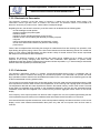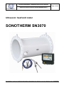
1
Product application, installation and service manual Page 1 of 24 ELIS PLZEŇ a. s. Ultrasonic heat/cold meter SONOTHERM SN3070 Ultrasonic heat/cold meter SONOTHERM SN3070 ELIS PLZEN a. s., Lucni 15, P. O. BOX 126, 304 26 Plzen, Czech Republic, tel.: +420/377 517 711, fax: +420/377 517 722 Es90474K/b Product application, installation and service manual Page 2 of 24 ELIS PLZEŇ a. s. Ultrasonic heat/cold meter SONOTHERM SN3070 CONTENT 1. APPLICATION .......................................................................................................................................................3 2. MEASUREMENT PRINCIPLES .............................................................................................................................3 3. TECHNICAL DESCRIPTION .................................................................................................................................5 2.1. 2.2. 3.1. 3.2. Measuring part of ultrasonic flow meter ................................................................................................................ 3 Measuring part of calorimeter ............................................................................................................................... 4 General description ............................................................................................................................................... 5 Meter connection to heating system ..................................................................................................................... 5 Fig. 2 - Meter connection to heating system .............................................................................................................5 3.3. Meter design ......................................................................................................................................................... 6 3.3.1. Ultrasonic sensor UC 7.0 .................................................................................................................................. 6 3.3.2. Electronic to flow meter .................................................................................................................................... 7 3.3.3. Calorimeter ....................................................................................................................................................... 7 4. TECHNICAL SPECIFICATIONS ............................................................................................................................8 5. METER APPLICATION DIRECTIONS AND RULES...........................................................................................11 6. METER ASSEMBLY AND INSTALLATION RULES ...........................................................................................14 7. OPERATIONAL START AND METER CONTROL .............................................................................................16 8. WARRANTY AND POST-WARRANTY SERVICES ............................................................................................20 9. TESTING ..............................................................................................................................................................21 4.1. 4.2. 4.3. 4.4. 5.1. 5.2. 5.3. 6.1. 6.2. 6.3. 6.4. 7.1. 7.2. 7.3. 8.1. 8.2. Rated inner diameters and limit flow rates for sensor UC 7.0 ............................................................................... 8 Technical parameters of Ultrasonic heat/cold meter SONOTHERM SN3070 ....................................................... 9 Communication ................................................................................................................................................... 10 Optional calorimeter accessories ........................................................................................................................ 10 Project design of systems including ultrasonic flow meters ................................................................................. 11 Data processing electronic unit ........................................................................................................................... 13 Resistance temperature sensor .......................................................................................................................... 13 Data processing electronic unit MTU 2.00 .......................................................................................................... 14 Electrical connections ......................................................................................................................................... 15 Ultrasonic sensor UC 7.0 .................................................................................................................................... 15 Mechanical connections ...................................................................................................................................... 15 Flow metering section ......................................................................................................................................... 16 Calorimetric section ............................................................................................................................................ 16 Displayed data and information ........................................................................................................................... 16 Warranty services ............................................................................................................................................... 20 Post-warranty services ........................................................................................................................................ 20 10. CALIBRATION AND VERIFICATION ..................................................................................................................21 11. ORDERING ..........................................................................................................................................................21 12. PACKING .............................................................................................................................................................21 13. PRODUCT ACCEPTANCE ..................................................................................................................................21 14. WARRANTY CONDITIONS .................................................................................................................................21 15. RATING PLATES.................................................................................................................................................22 ELIS PLZEN a. s., Lucni 15, P. O. BOX 126, 304 26 Plzen, Czech Republic, tel.: +420/377 517 711, fax: +420/377 517 722 Es90474K/b Product application, installation and service manual Page 3 of 24 ELIS PLZEŇ a. s. Ultrasonic heat/cold meter SONOTHERM SN3070 1. APPLICATION The meter system SONOTHERM SN3070 is intended for measurement of absolute heat/cold quantities (energy) transferred by water in closed-circle heating/cooling systems. It can be used as commercial meter to determine the heat/cold quantities used or transferred at heated/cooling premises, heat-exchanger stations or at heat/cold-generating plants. The system consists of a flow-measuring section (ultrasonic flow meter) and an electronic calorimeter including the necessary data processing and archiving facility. 2. MEASUREMENT PRINCIPLES 2.1. Measuring part of ultrasonic flow meter The flow meter section is based on a single-channel “transit-time” impulse method where the flow rate of the measured liquid is determined from the flight time of ultrasonic signal between the sensor probes. The ultrasonic signal is sent and flow-rate measurements are performed in turns in and against the flow direction whereby the error due to non-symmetric positions of the ultrasonic probes is eliminated. The ultrasonic signal propagation time in the flow direction in flow sensor UC 7.0 is defined by the equation t1 l l 1 c v.cos c 1 ULTRASONIC PROBE s FLOW SENSOR RATING PLATE FLOW DIRECTION Fig. 1 - Dimensional sketch of the measuring part where l c v l1 c1 - distance between the head parts of ultrasonic probes [m] - signal propagation speed in the given liquid [m/s] - flow speed of the measured liquid [m/s] - aggregate thickness of bottom parts of both probes [m] - signal propagation speed in the probe material [m/s] When the ultrasonic signal travels in the direction against the flow, the expression for the signal propagation time t2 differs from t1 in that the flow speed is negative: t2 l l 1 c v cos c 1 s Parameters l1 a c1 are constants for the given sensor probe. ELIS PLZEN a. s., Lucni 15, P. O. BOX 126, 304 26 Plzen, Czech Republic, tel.: +420/377 517 711, fax: +420/377 517 722 Es90474K/b Product application, installation and service manual Page 4 of 24 ELIS PLZEŇ a. s. Ultrasonic heat/cold meter SONOTHERM SN3070 The ultrasonic signal propagation speed can be expressed as follows: v 1 c v . cos for measurements in the flow direction v 2 c v . cos for measurements against the flow direction The difference between the ultrasonic signal propagation speeds in and against the flow direction is proportional to the liquid flow speed v [m/s]. v v1 v 2 2.cos The instantaneous flow rate can be determined using the equation: q v s k v where v s k(v) m / s 3 - liquid flow speed [m/s] - sensor cross-section [m2] - correction coefficient (a function of the instantaneous liquid speed). This coefficient modifies the resulting q with respect to the liquid flow speed profile in the sensor. 2.2. Measuring part of calorimeter The calculation of the heat power value uses the following formula; it is assumed that the heat exchanger is absolutely tight and no heating water is being extracted from the heating system. qt q m i1 t1 i2 t 2 q v t i1 t1 i2 t 2 with the following instantaneous parameter values: qt qm qv i1(t1) i2(t2) (t) t t1 t2 - heat power transferred by heating water - mass flow rate of heating water - volume flow rate of heating water - enthalpy of water in the feed piping - enthalpy of water in the return piping - specific density of heating water - water temperature at flow-rate measurement spot - water temperature (higher temperature of medium) - water temperature (lower temperature of medium) [J/h] [t/h] [m3/h] [J/kg] [J/kg] [kg/m3] [oC] [oC] [oC] The quantity of heat transferred Q is defined as the integral over time of the instantaneous heat power values: Q q t dt J t ELIS PLZEN a. s., Lucni 15, P. O. BOX 126, 304 26 Plzen, Czech Republic, tel.: +420/377 517 711, fax: +420/377 517 722 Es90474K/b Product application, installation and service manual Page 5 of 24 ELIS PLZEŇ a. s. Ultrasonic heat/cold meter SONOTHERM SN3070 3. TECHNICAL DESCRIPTION 3.1. General description The meter system SONOTHERM SN3070 determines the heat/cold quantity delivered or transferred by calculation in a calorimetric counter using data on the water volume passed through the ultrasonic flow meter and the water temperatures in the feed and return pipes. Type designation of meter systems and their component parts: System Accessory electronic unit SN3070 MTU 2.00 Flow sensor UC 7.0 The quantity of heating/cooling water passed through the feed or return piping is measured by means of an ultrasonic flow meter. The water temperatures in the feed and return pipes are measured by two resistance platinum temperature sensors Pt 100 or Pt 500. These measured data are processed in a calorimetric counter with LCD display. The operator can select the data to be displayed using a multifunction control button (see the table defining the display codes in either Operational or Testing modes on page 16 – Chapter 7). Electronic communication with the meter system is possible using either the M-Bus interface (EN 1434-4 standard) or the IR interface on the front panel. The M-Bus signals are connected to the meter terminal board. In the cases of a line voltage failure, the ultrasonic flow meter will discontinue operation but not the calorimeter where a back-up battery will supply the necessary power. The calorimeter will thus save all hitherto measured data and record the period of power down time. The calorimetric counter also has specific diagnostic functions; it can identify thermometer failures (shorts or open circuits) or their combinations – see the error codes on page 19. 3.2. Meter connection to heating system Fig. 2 - Meter connection to heating system Cooling system: Thermometers for measuring of cold have to be connected to the piping by opposite way. Description of connection is in chapter 6.2. ELIS PLZEN a. s., Lucni 15, P. O. BOX 126, 304 26 Plzen, Czech Republic, tel.: +420/377 517 711, fax: +420/377 517 722 Es90474K/b Product application, installation and service manual Page 6 of 24 Ultrasonic heat/cold meter SONOTHERM SN3070 ELIS PLZEŇ a. s. 3.3. Meter design 3.3.1. Ultrasonic sensor UC 7.0 The sensor body is a welded piece consisting of two end flanges to be connected to the piping, the main pipe section and two pipe branches holding the ultrasonic probes (see Fig. 1). In the standard sensor version the body is designed for operating pressure PN 10, made of high-quality steel and the flanges are according to standard ČSN EN 1092-1; the whole assembly is coated with powder epoxy paint KOMAXIT E 2310 of light grey hue (RAL 7035). On special request, the sensor body can be supplied: - in a stainless-steel version - with ANSI or JIS flanges - in version for PN 16 or PN 25 (piping sizes up to DN 500) Sensors for application in drinking-water supply systems are coated with powder epoxy paint KOMAXIT E 2110 of blue hue (RAL 5017). Fig. 3 - Dimensional sketch of the meter sensor DN 200 250 300 350 400 450 500 600 700 800 1000 1200 NPS 8“ 10“ 12“ 14“ 16“ 18“ 20“ 24“ 28“ 32“ 40“ 48“ L [mm] 600 650 700 750 800 850 900 700 800 850 1000 1150 D [mm] 340 395 445 505 565 615 670 780 895 1015 1230 1455 Weight [kg] 41,5 53,5 68 89 113 136 161 182 292 378 632 978 Table 1 - Sensor dimensions ELIS PLZEN a. s., Lucni 15, P. O. BOX 126, 304 26 Plzen, Czech Republic, tel.: +420/377 517 711, fax: +420/377 517 722 Es90474K/b Product application, installation and service manual Page 7 of 24 ELIS PLZEŇ a. s. Ultrasonic heat/cold meter SONOTHERM SN3070 3.3.2. Electronic to flow meter The electronic accessory to the flow meter is housed in a plastic box with internal metal coating. The calorimetric counter, type MTU 2.00, is located in the same box. The ultrasonic sensor is connected to its electronic accessory by means of two coaxial cables of adequate length. Regarding function, the electronic accessory to the flow meter can be divided into the following parts: - circuits isolating the meter probes - switches controlling the probe signals - ultrasonic sender - ultrasonic receiver including sensitivity-control circuitry - interface circuits communicating with the data processing computer - computer - output circuits generating impulses for the calorimetric counter - circuits of the serial communication line (the flow-meter setting) - power source. There is also an adaptive filter eliminating fast changes of instantaneous flow rate resulting from pulsation of the liquid flowing through the piping, actions of the flow-control elements and other disturbing events from outside the piping. In a flow meter of standard design, this filter causes a delay of several seconds of the sensor output data with respect to the actual flow rate in the sensor. However, the electronic accessory of the ultrasonic flow meter can be modified so as to ensure a very fast response to the quickly changing mass flow data. This modification finds application in systems where instantaneous flow rate needs be measured and monitored as fast as possible, e.g. in heat exchanger and transfer stations where fast regulation processes take place. 3.3.3. Calorimeter The electronic calorimetric counter is a modern microprocessor-based device used in combination with an ultrasonic flow meter to measure heat energy for commercial purposes. The calorimeter can process and store large quantities of data so that the user has detailed information on the current status of the measuring point as well as the measured data over long periods of time. The counter input receives signals from the impulse sender of the flow meter and two temperature sensors. With each impulse from the flow meter received, the temperatures of the incoming and outgoing liquid are measured. The temperature data and flow meter impulses are stored in the internal memory circuits of the counter. The heat energy data are calculated using the data on the temperature difference, flow rate and the associated thermal coefficients; these data are integrated in the counter memory and their aggregate values shown on the counter display. If the frequency of the output impulses from the flow meter is higher than 1Hz, the impulses (representing the flow volume passed through the meter) are cumulated and the heat measurements are taken once a second. If the interval between impulses exceeds 60s, each 60s temperature readings are taken and shown on the counter display; but the heat measurement/calculation takes place only after the next impulse from the flow meter is received. ELIS PLZEN a. s., Lucni 15, P. O. BOX 126, 304 26 Plzen, Czech Republic, tel.: +420/377 517 711, fax: +420/377 517 722 Es90474K/b Product application, installation and service manual Page 8 of 24 Ultrasonic heat/cold meter SONOTHERM SN3070 ELIS PLZEŇ a. s. 4. TECHNICAL SPECIFICATIONS 4.1. Rated inner diameters and limit flow rates for sensor UC 7.0 Using Table 2, select the correct sensor size with respect to the required measuring range. The data in the Table are taken from standard ČSN EN 14154-1. Rated piping diameter DN 200 250 300 350 400 450 500 600 700 800 1000 1200 Q4 overload flow rate Q3 permanent flow rate Q2 transitional flow rate Q1 minimum flow rate m3/h 1000 1200 1500 1800 2000 2300 2500 3000 3600 4100 5100 6100 G/min 4403 5283 6604 7925 8806 10127 11007 13209 15850 18052 22455 26857 m3/h 800 960 1200 1440 1600 1840 2000 2400 2880 3280 4080 4880 G/min 3522 4227 5283 6340 7045 8101 8806 10567 12680 14441 17964 21486 3 16 19,2 24 28,8 32 36,8 40 48 57,6 65,6 81,6 97,6 140,89 162,02 176,11 211,34 253,60 288,83 359,27 429,72 m /h G/min 70,44 3 15 18 20 23 25 30 36 41 51 61 52,83 66,04 79,25 88,06 101,27 110,07 132,09 158,5 180,52 224,55 268,57 2,3 3,6 5,1 7,0 9,1 11,5 14,2 15 18 20,5 25,5 30,5 10,1 15,8 22,4 30,8 40,1 50,6 62,5 66,0 79,2 90,2 112,3 134,3 l/imp 500 500 500 1000 1000 1000 2000 2000 5000 5000 10000 10000 G/imp 100 200 200 200 200 500 500 500 500 1000 1000 1000 G/min 44,03 3 m /h QNEC suppressed flow G/min Pulse output constant k i 105,67 126,80 12 m /h 10 84,53 Table 2 - Ranges of measured values for given piping sizes The threshold flow rate (QNEC) is the minimum flow rate at which the meter starts to indicate and process the fluid flow parameters. At the manufacturer’s plant, QNEC is set at a value corresponding to the flow velocity of 20mm/s. On customer’s request, the threshold flow rate can be set at any value within the range of QNEC = 0.1 25% Q4. The maximum permitted error in fluid volume measurements at flow rates between Q1 (including) and Q2 (excluding) is: 5% irrespective of the fluid temperature. The maximum permitted error in fluid volume measurements at flow rates between Q2 (including) and Q4 (including) is: 1% for the fluid temperature not exceeding 50°C, and 3% for the fluid temperature greater than 50°C. ELIS PLZEN a. s., Lucni 15, P. O. BOX 126, 304 26 Plzen, Czech Republic, tel.: +420/377 517 711, fax: +420/377 517 722 Es90474K/b Product application, installation and service manual Page 9 of 24 ELIS PLZEŇ a. s. Ultrasonic heat/cold meter SONOTHERM SN3070 4.2. Technical parameters of Ultrasonic heat/cold meter SONOTHERM SN3070 Piping I.D. DN200 to DN1200 Rated pressure PN 10, on request PN 16 or PN 25 for piping sizes DN200 to DN500 Measurement precision of flow meter ± 1% for flow rate Q > Q2 (see Table 2) and fluid temperature up to 50°C Fluid temperature 0 to +150°С Ambient temperature +5 to +50°С Ambient relative humidity not exceeding 80% Storage temperature -10 to 70 °C at relative humidity not exceeding 70 % Temperature difference t 3 to 120 °C Visual output via LCD, 7 + 2 digits from zero to nine Power source 90 to 260 V, 50/60 Hz Back-up power source Li battery 3 V (lifetime 5 years) Power requirement 12VA Line fuse T 250mA, 250V Protection against electric shock according to standard ČSN 332000-4-41 Protect. class; electronic unit Protect. class; sensor, probes Outputs automatic disconnection from power source in the TN – S network IP 65 IP 54 (on request IP 68) M-Bus (standard EN 1434-4, IEC 870) IR opto coupler Optional accessories extended range of fluid temperature (up to +180°C) sensor protection class IP 68 drinking-water meter version sensor flanges according to alternative standards (ANSI, JIS) Table 3 - flow meter specifications ELIS PLZEN a. s., Lucni 15, P. O. BOX 126, 304 26 Plzen, Czech Republic, tel.: +420/377 517 711, fax: +420/377 517 722 Es90474K/b Product application, installation and service manual Page 10 of 24 ELIS PLZEŇ a. s. Ultrasonic heat/cold meter SONOTHERM SN3070 4.3. Communication System SONOTHERM SN3070 is provided with communication interface M-Bus (standard EN1434-4) with the respective signals connected to the meter terminal board, and IR interface accessible via a window in the front panel. The measured data can be transferred using both interface systems. 4.4. Optional calorimeter accessories On request, the calorimetric counter can be supplied with the following optional devices/functions: - display with illuminated background When using other optional devices, it should be noted that there are two free terminals available (marked as “rez.” – reserve) where any of the following signals can be connected: - impulse output of the “heat energy” or “volume” signals (open-collector output, UCE max = 24 V, ICE max = 20 mA, impulse length 250 ms) - impulse input – impulse counter for “hot water” or other signals (contact input, fmax = 12 Hz, impulse length 40 ms, max. voltage 3 V) - communication interface SIOX-Bus (compatible with meters of the model series SWM 820, SWM 690 and other measuring systems based on such devices) - alarm signal (open-collector output, UCE max = 24 V, ICE max = 20 mA, impulse length 250 ms). - protection of sensor IP 67 ELIS PLZEN a. s., Lucni 15, P. O. BOX 126, 304 26 Plzen, Czech Republic, tel.: +420/377 517 711, fax: +420/377 517 722 Es90474K/b Product application, installation and service manual Page 11 of 24 Ultrasonic heat/cold meter SONOTHERM SN3070 ELIS PLZEŇ a. s. 5. METER APPLICATION DIRECTIONS AND RULES 5.1. Project design of systems including ultrasonic flow meters In designing any project it is necessary to observe specific rules concerning placement of the meter sensors in piping so that the measuring precision would not be adversely affected. In the case of the meter sensor UC7.0, the required lengths of straight piping sections before and after the meter sensor are 5DN and 3DN, respectively (see Fig. 4, 5). 5 DN 3 DN 5 DN FLOW DIRECTION 3 DN FLOW DIRECTION Fig. 4 - Minimum lengths of straight piping sections Fig. 5 - Minimum length of straight piping section at the input side of closing valve If there is a pump near the meter sensor, it should be located at the distance of at least 20DN from the sensor output (see Fig. 6). 20 DN FLOW DIRECTION Fig. 6 - Minimum length of straight piping section before a pump In cases where complete flooding of the piping cannot be guaranteed at all times, the meter sensor should be located so as to ensure meeting of this condition (see Fig. 7). 3 DN 5 DN 3 5 DN DN OW FL CT RE DI N IO FLOW DIRECTION Fig. 7 - Sensor locations ensuring complete flooding at all times ELIS PLZEN a. s., Lucni 15, P. O. BOX 126, 304 26 Plzen, Czech Republic, tel.: +420/377 517 711, fax: +420/377 517 722 Es90474K/b Product application, installation and service manual Page 12 of 24 ELIS PLZEŇ a. s. Ultrasonic heat/cold meter SONOTHERM SN3070 FLOW DIRECTION If the sensor is to be fitted into a vertical piping section, the fluid flow direction in such section shall be upwards (see Fig. 8). Fig. 8 - Sensor fitted into a vertical piping section FLOW DIRECTION FLOW DIRECTION Errorless meter operation cannot be guaranteed unless the sensor is completely filled with the measured fluid at all times. Therefore the sensor should not be located at the highest piping sections or in vertical piping sections if the fluid flow direction is downwards, in particular in situations where there is a piping outlet into open reservoirs or tanks anywhere near (see Fig. 9). Fig. 9 - Examples of incorrect sensor placement Another factor that may influence the meter function is the sensor angle position with respect to its longitudinal axis. Occasional air bubbles in the piping may get caught in the hollow welded-on probe holders where they would disrupt the measuring process. To effectively prevent this from occurring, the sensor probes should best be in the horizontal plane (see Fig. 10). If for any reason such position is not possible, the sensor body may be fitted in angular position where the probe plane and horizontal plane form an angle of not more than 30°. ELIS PLZEN a. s., Lucni 15, P. O. BOX 126, 304 26 Plzen, Czech Republic, tel.: +420/377 517 711, fax: +420/377 517 722 Es90474K/b Product application, installation and service manual Page 13 of 24 ELIS PLZEŇ a. s. Ultrasonic heat/cold meter SONOTHERM SN3070 30° PROBE 2 30° PROBE 1 Fig. 10 - Permitted range of the meter sensor rotation with respect to its longitudinal axis. 5.2. Data processing electronic unit In the cases of a commercial meter application, the data-processing electronic unit shall have an independent power supply line 230V, 50Hz with an over current circuit breaker (the recommended rating 6A) that can be sealed in the ON position. Arrangements should be made so that the power supply can only be disconnected by duly authorised staff. The recommended type of power supply cable is CYKY 3 x 1,5mm2, outer diameter 10.5mm. 5.3. Resistance temperature sensor The water temperature measurements can be made using thermometers including resistance temperature sensors Pt 100 or Pt 500, provided such thermometers have been type-tested and approved for use in Czech Republic. The thermometers used in commercial heat meters shall comply with the requirements in Code 505/1990 Coll., be type-approved, metrological verified by the National Metrological Centre and be supplied in pairs with the temperature reading differences over the whole range of measured temperatures not exceeding 0.05°C. Each temperature sensor shall be connected by two wires. Temperature sensors Pt 100 and Pt 500 Maximum length of connecting wires: 2.5m for wire cross-section 0.22mm2 5.0m for wire cross-section 0.50mm2 7.5m for wire cross-section 0.75mm2. Maximum current loading: 4μA RMS (for sensor Pt 100). ELIS PLZEN a. s., Lucni 15, P. O. BOX 126, 304 26 Plzen, Czech Republic, tel.: +420/377 517 711, fax: +420/377 517 722 Es90474K/b Product application, installation and service manual Page 14 of 24 ELIS PLZEŇ a. s. Ultrasonic heat/cold meter SONOTHERM SN3070 6. METER ASSEMBLY AND INSTALLATION RULES The meter assembly and installation work shall be done in strict observance of the directions and principles listed in this Manual. To prevent electric interference, the power cables shall be led at least 25cm away from all signal cables associated with the flow meter (i.e. the coaxial cables connecting sensor UC 7.0, the cables from temperature sensors, M-Bus interface signal cables and all input and output impulse signal cables). Should any signal cables need be extended, the connections shall be done by soldering and the soldered joints shall be protected from climatic or mechanical stresses by placing in a suitable installation box. All cables shall be led outside the thermal insulation layers on the water piping. The temperature sensors shall be connected by shielded conductors. The shields shall be connected to the earth potential on one side only, on the terminal board X10 of the electronic accessory. Sensor must be grounded properly. For grounding use a conductor with minimum cross section area 4 mm2 and connect the conductor to grounding bolts of evaluation electronic and flow sensor (see figure here below). Earthing connection between the MTU 2.00 electronic unit and the flow sensor. Fig. 11 - Earthing connection between the MTU 2.00 electronic unit and the flow sensor. 6.1. Data processing electronic unit MTU 2.00 The electronic unit shall be mounted in a perpendicular position on a wall or support plate by means of an assembly frame. The electrical connections between the electronic unit and the flow sensor UC 7.0 shall be done as described in Section 6.2 below. The difference in lengths of the connecting coaxial cables shall not be greater than 0.1m. ELIS PLZEN a. s., Lucni 15, P. O. BOX 126, 304 26 Plzen, Czech Republic, tel.: +420/377 517 711, fax: +420/377 517 722 Es90474K/b Product application, installation and service manual Page 15 of 24 ELIS PLZEŇ a. s. Ultrasonic heat/cold meter SONOTHERM SN3070 6.2. Electrical connections Use the schematic drawing below to connect the MTU 2.00 electronic unit to the flow sensor probes. Pay particular attention to the probe 1 and 2 positions with respect to the flow direction. Schematic drawing of electrical connections between MTU 2.00 and associated devices Fig. 12 - Electrical connections Heating system: T1 - thermometer in the feed piping (higher temperature, F) T2 – thermometer in the return piping (lower temperature, R) Cooling system: T1 - thermometer in the return piping (higher temperature, R) T2 – thermometer in the feed piping (lower temperature, F) Connection of thermometers Pt100 and Pt500 is identical. Connector CANON 9 for RS 232 shall be used only for meter servicing purposes. 6.3. Ultrasonic sensor UC 7.0 The ultrasonic flow sensor shall be mounted directly on the piping, with the thermal insulation removed. The connecting coaxial cables shall not be attached to the hot-water piping. When installing the sensor into the piping, make sure that the inner sensor space be completely filled with water at all times. During measurement, water shall not leave the sensor space nor air be allowed to enter it. If the sensor is mounted in a vertical position, the only permitted water flow direction is upwards. Disregarding the meter installation principles listed in Section 5 may result in measurement errors. 6.4. Mechanical connections The ultrasonic sensor shall be fitted into the fluid piping by means of flanges ensuring exact match with the respective counter-flanges on the piping ends (see the specifications on the flange circumference). Unless required otherwise, the sensor shall be supplied with flanges according to standard ČSN EN 1092-1 (the alternative solutions are ANSI or JIS flanges). The box housing the electronic accessory can be mounted onto a vertical support plate using four bolts of diameter 5 mm. ELIS PLZEN a. s., Lucni 15, P. O. BOX 126, 304 26 Plzen, Czech Republic, tel.: +420/377 517 711, fax: +420/377 517 722 Es90474K/b Product application, installation and service manual Page 16 of 24 ELIS PLZEŇ a. s. Ultrasonic heat/cold meter SONOTHERM SN3070 7. OPERATIONAL START AND METER CONTROL 7.1. Flow metering section As soon as the flow sensor has been installed in the piping and the electrical connections between the sensor and its electronic unit have been made, the system can be connected to power. Within a short time the flow meter starts its measuring functions. Connector X4 is reserved for calibration purposes, parameter setting in production and servicing. Ultrasonic sensor UC 7.0 is connected to the associated data processing unit by means of two coaxial cables (see the respective schematic diagram). If the system is used as a standard meter, switch S3 located under the box lid provided with the official mark and one half of switch S2 are used in production and for metrological purposes. The functions of the remaining half of switch S2 are described in the following table. Switches S3 and S2: setting combinations Measurement mode S3:2 in position OFF Servicing mode Programming mode S3:2 in position OFF S3:2 in position ON S2:1 in position OFF S2:2 in position OFF S2:2 in position ON S2:2 in position OFF Table 4 - Switches S3 and S2 7.2. Calorimetric section As soon as the temperature sensors have been installed and electrically connected, the calorimeter functions can be tested using the respective display code table. Upon delivery, the calorimeter will be set at the “transport mode” where no measurements are performed and only the real time function is operative. With the transport mode selected, the display shows the word “no” in the upper left corner. To select the “operation mode”, depress the display push-button and hold in the depressed position for about 5s. 7.3. Displayed data and information The upper-line symbol identifies the measured quantity displayed. Display code This symbol flashes once for each flow meter impulse received Symbol stays lighted in the case of error ELIS PLZEN a. s., Lucni 15, P. O. BOX 126, 304 26 Plzen, Czech Republic, tel.: +420/377 517 711, fax: +420/377 517 722 Es90474K/b Product application, installation and service manual Page 17 of 24 ELIS PLZEŇ a. s. Ultrasonic heat/cold meter SONOTHERM SN3070 Data and information measured/transferred * Accumulated (heat/cold) energy * Quantity of impulses at both additional impulse inputs (optional solution on customer order) * Error code and duration of actual error * Instantaneous power * Instantaneous flow rate * Input temperature * Output temperature * Temperature difference * Operational period * Meter number * Production series number * Real time and function date * Litres per impulse parameter * Flow meter location (feed or return piping) * Readings on the selected date when the following data are stored in the system memory - calendar date - accumulated energy - accumulated flow volume measured by flow meter - accumulated flow volume used in energy calculations - accumulated number of impulses at impulse inputs (optional meter configuration) - error code (if any) of error occurring at the time of data storage action * Accumulated flow volume measured by flow meter * Accumulated flow volume used in energy calculations * Total period of error duration * Previous error code – error type and duration * Up to 37 monthly memory registers where each register contains the same type of data as those listed under „Readings on the selected date“ * Recommended battery replacement date ELIS PLZEN a. s., Lucni 15, P. O. BOX 126, 304 26 Plzen, Czech Republic, tel.: +420/377 517 711, fax: +420/377 517 722 Es90474K/b Product application, installation and service manual Page 18 of 24 ELIS PLZEŇ a. s. Ultrasonic heat/cold meter SONOTHERM SN3070 Display codes on the system LCD in the “operating” and “testing” modes of operation DISPLAY CODE 10 11 12 13 14 15 16 20 21 22 23 24 30 31 32 33 34 35 36 37 40 41 42 43 44 45 46 47 50 51 52 53 60 AX BX 63 64 70 71 72 73 74 75 DISPLAYED DATA OR INFORMATION Operating mode Accumulated energy Accumulated flow volume measured by flow meter LCD test Impulse register 1 – accumulated value (on customer order) Impulse register 2 – accumulated value (on customer order) Error code Error duration – total time of actual error Instantaneous power Instantaneous flow rate Input temperature (T1) Output temperature (T2) Temperature difference (T) Readings on selected data (Date of memory storage) Accumulated energy Accumulated flow volume measured by flow meter Accumulated flow volume used in energy calculations Impulse register 1 – accumulated value Impulse register 2 – accumulated value Error code (any error existing on date of data memory storage) Total error time (if any) Regular monthly readings – date of data memory storage Accumulated energy Accumulated flow volume measured by flow meter Accumulated flow volume used in energy calculations Impulse register 1 – accumulated value Impulse register 2 – accumulated value Error code (any error existing on date of data memory storage) Total period of error duration (if any) Meter operation time Actual date Actual time Recommended battery replacement date Communication address Meter number Production series number Flow meter impulse input setting – litres per impulse Flow meter location in piping branch T2 (L) or T1 (H) Accumulated flow volume used in energy calculations Last recorded and communicated value of accumulated energy Time of last communication Error duration – total period of actual error duration Previous error code Total period of previous error duration Table 5 - Display codes FORMAT Minutes RRMMDD Minutes RRMMDD Minutes Hours RRMMDD HHMM RRMMDD Litres/impulse L,H Hour Minutes Minutes To switch over between code groups, depress the push-button and hold it depressed for longer time. To switch from one code to the next within a code group depress the push-button shortly. Display format explanation: RRMMDD RR ... last two digits of year, MM ... month, DD ... day in the month HHMM HH ... hours, MM ... minutes ELIS PLZEN a. s., Lucni 15, P. O. BOX 126, 304 26 Plzen, Czech Republic, tel.: +420/377 517 711, fax: +420/377 517 722 Es90474K/b Product application, installation and service manual Page 19 of 24 ELIS PLZEŇ a. s. Ultrasonic heat/cold meter SONOTHERM SN3070 Comments/explanations: 1) The calorimetric counter has two registers to store data on accumulated flow volume; register 11 contains data on the total accumulated flow volume passed through the flow meter, register 70 contains data on the accumulated flow volume used in heat value calculations. Differences in the data stored in these registers can help identify errors in the temperature sensors whose signals are used for energy calculations. 2) To display the next reading on specified date, depress the push-button until you arrive at change of date. After passing through display code 37, the last reading on specified date will be displayed. Then depress the push-button to return to the normal display mode. 3) To display the next monthly reading on specified date, depress the push-button until you arrive at change of date. After passing through display code 47, the last monthly reading on specified date will be displayed. Then depress the push-button to return to the normal display mode. 4) The right character (X) in the display code AX is a supplementary number to the meter number. 5) The right character (X) in the display mode BX is a supplementary number to the production series number. Error code There are available three error display modes: - in display code “15” ... actual error - in display code “36” ... error existing at the time of data reading and storage - in display code “46” ... error existing at the time of regular monthly reading. Error codes Error code 0001 0002 0003 0004 0005 0006 0007 0008 0009 000A 000b 000c 000d 000e 000F 0010 0011 - 001F 0020 0021 - 003F 0040 0041 - 007F 0080 0081 - 00FF 0100 0101 - 01FF Type of error Output thermometer (T2), open circuit Output thermometer (T2), short circuit Errors 0001 + 0002 * Input thermometer (T1), open circuit Errors 0001 + 0004 Errors 0002 + 0004 Errors 0001 + 0002 + 0004 * Input thermometer (T1), short circuit Errors 0001 + 0008 Errors 0002 + 0008 Errors 0001 + 0002 + 0008 * Errors 0004 + 0008 * Errors 0001 + 0004 + 0008 * Errors 0002 + 0004 + 0008 * Errors 0001 + 0002 + 0004 + 0008 * Electronic unit (error in EEPROM) Combination of error 0010 and any above error(s) Electronic unit (error in “Inter-Bus”) Combination of error 0020 and any above error(s) Low flow rate Combination of error 0040 and any above error(s) Power supply failure - line voltage 230V or bus power Combination of error 0080 and any above error(s) Recommended battery replacement date not observed Combination of error 0100 and any above error(s) Table 6 - Error codes ELIS PLZEN a. s., Lucni 15, P. O. BOX 126, 304 26 Plzen, Czech Republic, tel.: +420/377 517 711, fax: +420/377 517 722 Es90474K/b Product application, installation and service manual Page 20 of 24 ELIS PLZEŇ a. s. Ultrasonic heat/cold meter SONOTHERM SN3070 The most frequent errors in the table are printed in bold type. The remaining errors may occur only rarely. Errors marked with “*“ will not occur if the electronic accessory works correctly. Instantaneous values Instantaneous power value (display code 20) and instantaneous flow rate (display code 21) are calculated only subsequently. If the impulses from the flow meter arrive in intervals longer than 4 seconds, the values of instantaneous power and flow rate are calculated after each new impulse. If this interval is shorter than 4 seconds, the impulses are cumulated and the instantaneous value calculations are carried out every 4 seconds. 8. WARRANTY AND POST-WARRANTY SERVICES 8.1. Warranty services Warranty services are understood to be repairs of products executed free of charge during the contractually agreed warranty period. Such repairs can either be performed at the manufacturer’s plant or at that of any authorised partner of the manufacturer. Warranty repair is understood to be repair of any product defects due to faulty materials, parts or product design, executed free of charge within a period agreed between the customer/user and the meter manufacturer. Should any meter defect be proved irreparable due to the above reasons, the manufacturer shall replace it by a new faultless product of the same type. Warranty services can only be performed by the manufacturer (ELIS PLZEN a.s.) or a duly authorised service centre or a product distributor who have received valid authorisation in writing and have been trained in the necessary skills by the manufacturer. Warranty services shall not be applicable to: - products with damaged company or metrological seals - defects due to incorrect product assembly and/or installation - defects due to incorrect product application - product theft or pilferage - defects due to force majeure circumstances Any requirement regarding warranty services shall be made known to the manufacturer in writing (using Email, fax or registered letter). Should the manufacturer not acknowledge the user’s warranty claim as justified, it shall inform the user accordingly in writing and invoice to the same the repair costs involved. In the cases of any warranty repairs performed on standard meters, the meter parameters shall consequently be verified at the respective National Metrological Centre. 8.2. Post-warranty services Post-warranty services are understood to be repairs of any and all product defects originating after the mutually agreed warranty period. Such repair, whether performed at the manufacturer’s plant or elsewhere, as directed by the customer, shall be invoiced to the customer who shall be obliged to pay the invoiced sums. In the cases of post-warranty repairs of standard meters, the meter parameters shall consequently be verified at the respective National Metrological Centre. Any requirement regarding post-warranty services shall be made known to the manufacturer in writing (using E-mail, fax or registered letter). ELIS PLZEN a. s., Lucni 15, P. O. BOX 126, 304 26 Plzen, Czech Republic, tel.: +420/377 517 711, fax: +420/377 517 722 Es90474K/b Product application, installation and service manual Page 21 of 24 ELIS PLZEŇ a. s. Ultrasonic heat/cold meter SONOTHERM SN3070 9. TESTING On every product, the manufacturer performs a detailed inspection of the product completeness and quality in reference to the respective quality assurance standards. Following this inspection the product is subject to tests performed in compliance with the agreed test specifications. Prior to release from the test station, every product is subject to a test run over a minimum period of 15 hours. 10. CALIBRATION AND VERIFICATION In the cases of standard meters, the manufacturer shall provide for primary verification of the correct design of the flow meter and calorimetric sections at the Authorized Metrological Centre. The ultrasonic flow meter is tested and metrological verified at three specified operational modes within the required flow rate range. On customer’s request and/or in the cases of higher precision requirements, the calibration measurements can be performed at as many as 9 modes within the measuring range. Important notice: It is recommended that the calibration measurements and verification of the flow meter section of SONOTHERM SN3070 at a certified testing centre be performed on a test stand in a continuous mode of operation. 11. ORDERING In ordering a product, the customer shall use the enclosed Product Order Form. 12. PACKING The product packing shall ensure safe domestic and international transport, taking into account the delivery conditions agreed to with the customer. The packing shall comply with the internal standards of the manufacturer (ELIS PLZEN a. s.). 13. PRODUCT ACCEPTANCE Upon delivery, the goods shall be checked for completeness with respect to the delivery note and subject to visual inspection. A typical scope of delivery includes a complete system SONOTHERM SN3070, operation and maintenance manuals, product compliance certificate and delivery note. 14. WARRANTY CONDITIONS Unless agreed within the commercial contract otherwise, the standard product warranty period is 12 months from the date of sale. Within the warranty period all product defects due to material and/or part faults shall be repaired free of charge. The warranty period shall be extended by the time the product was inoperative due to a warranty repair. Warranty shall not be applicable to any product defects due to incorrect system assembly and/or installation, intentional damage, pilferage, theft or any faults due to circumstances classified as force majeure. ELIS PLZEN a. s., Lucni 15, P. O. BOX 126, 304 26 Plzen, Czech Republic, tel.: +420/377 517 711, fax: +420/377 517 722 Es90474K/b Product application, installation and service manual Page 22 of 24 ELIS PLZEŇ a. s. Ultrasonic heat/cold meter SONOTHERM SN3070 15. RATING PLATES Flow sensor label Electronic unit label ELIS PLZEŇ a. s. ELIS PLZEŇ a. s. TYPE S/N DIMENSION DN m kg PROTEC. PRESS.PN MPa LIQUID TEMPERATURE 0 ÷ 150 oC MEDIUM FLOW DIRECT. TYPE SUPPLY VOLTAGE INPUT POWER PROTECTION S/N 230 V/50 Hz 6W IP 65 System label SYSTEM LABEL SN3070 SERIES NUMBER: CERTIFICATE No. COM. ADRESS NOMINAL HEAT/COLD RATE o C MEASURED SYSTEM NOMINAL HEAT/COLD DIFFERENCE o C Qmax OF FLOW METER MINIMUM HEAT/COLD DIFFERENCE o C PLACING OF FLOW METER CLASS OF ACCURACY TEMP. SENSOR 3 m /h FLOW SENSOR piping PROD. No. ELIS PLZEN a. s., Lucni 15, P. O. BOX 126, 304 26 Plzen, Czech Republic, tel.: +420/377 517 711, fax: +420/377 517 722 Es90474K/b Product application, installation and service manual Page 23 of 24 ELIS PLZEŇ a. s. Ultrasonic heat/cold meter SONOTHERM SN3070 ELIS PLZEŇ a.s. Product order form SN3070 Project: Measurement location: Project item: Required type of system Parameter to be specified Parameter value Units Minimum flow rate m3/hour Maximum flow rate m3/hour Type of measured liquid Temperature range of measured liquid °C Rated pressure of measured liquid 16 Rated inner diameter of sensor UC 7.0 DN 40 * Chapter 4.1 Length of cables to sensor UC 7.0 m Placing of flow meter Feed piping (F) Return piping (R) Communication via M-Bus Yes No * M-Bus communication address (range 1 to 250) Yes No * Optional accessories required Yes No * Chapter 4.4 Display with illuminated background Yes No * Stainless version of sensor UC 7.0 Yes No * Impulse output - energy Yes No * GJ/imp Impulse output - volume Yes No * m3/imp Impulse input Yes No * imp. number Communication via SIOX-Bus Yes No * Alarm signal Yes No * Counter flanges, packing and connecting parts and materials Yes No * (Enclose detailed specification) Flow meter verification in more than three operational modes within the measuring range Yes No - Customer address Company identification number Bank contact Contact person Telephone Fax Table 7 - Product order form Comment: The response time of the accessory electronic unit (if required in any particular application) can be modified on agreement with the customer. The standard meter configuration includes an adaptive filter. * Cross out if inapplicable ELIS PLZEN a. s., Lucni 15, P. O. BOX 126, 304 26 Plzen, Czech Republic, tel.: +420/377 517 711, fax: +420/377 517 722 Es90474K/b Product application, installation and service manual Page 24 of 24 ELIS PLZEŇ a. s. Ultrasonic heat/cold meter SONOTHERM SN3070 Manufacturer’s address: ELIS PLZEN a. s. Lucni 15, P. O. BOX 126 304 26 Plzen Czech Republic Tel.: +420/377 517 711 Fax: +420/377 517 722 e-mail: [email protected] http://www.elis.cz Issue No. 3 Date 18/12/2012 ELIS PLZEN a. s., Lucni 15, P. O. BOX 126, 304 26 Plzen, Czech Republic, tel.: +420/377 517 711, fax: +420/377 517 722 Es90474K/b