1
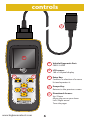
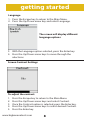
www.bigbananatools.com
BB700 instruction manual
contents
Table of Contents
Safety Precautions
Vehicle Inspection
Tool Description
Controls
Getting Started
Main Menu Settings
Language
Contrast
Display Test
Keypad Test
Units of Measurement
Where’s the Vehicle’s OBD?
Connecting the BB700
Operation Instructions
Diagnostics
Reading Trouble Codes
Erasing Trouble Codes
View Live Data
View Freeze Frame Data
I/M Status
Vehicle Information
Oxygen Sensor Test
Mode 6 Test
EVAP Systems Test
Update / Warranty & Servicing
Appendix a
Appendix b
Appendix c
www.bigbananatools.com
2
2
3
4
5
6
7
7
8
9
9
9
10
10
11
12
11
14
16
17
18
19
20
21
24
25
26
27
29
30
SAFETY FIRST!
For your safety, read this user manual before using the scan tool. Read your
vehicle’s service manual and follow all safety precautions.
DO NOT CONNECT, OR DISCONNECT, THE
SCAN TOOL TO YOUR VEHICLE WHILE THE
IGNITION IS ON. DOING SO CAN DAMAGE
YOUR VEHICLE’S ELECTRONICS.
Make sure the parking brake is engaged. For an automatic transmission, make sure
the transmission is in park. For manual transmissions, make sure the transmission
is in neutral and the parking brake is set.
The ignition must be in the OFF position prior to connecting/ disconnecting the
scan tool. Failure to do so could damage the scan tool and the vehicle’s electronic
components.
When the engine is turned on, operate the vehicle in a well-ventilated area.
Wear protective gear such as ANSI safety glasses, proper clothing, and gloves.
Be aware of fast moving parts such as belts, fans, and other moving components.
Always remain at a safe distance while the engine is running.
Do not touch hot engine parts. Serious burns can happen if proper protective gear
(safety gloves, safety glasses) are not worn.
Never smoke or have open flames around a vehicle that is being tested. Fuel and
battery fumes are extremely flammable and can cause an explosion.
Never leave tools on a vehicle’s battery.
When working around airbag components or wiring, follow the vehicles’ safety
manual for instructions. Unintended deployment of an airbag can cause serious
injuries and even death. Be aware that an airbag can still deploy several minutes
after the ignition is turned off.
To preserve the electronics of your handheld scanner, only connect one device at
a time to your vehicle’s Data Link Connector (DLC) port. Using another device, with
more than a 10 megohm impedance, can damage your scan tool and vehicle.
3
www.bigbananatools.com
vehicle inspection
This scan tool is designed to read your vehicle’s emissions-related
faults and retrieve fault codes related to a malfunction with these
systems.
Simple mechanical problems can cause poor engine performance and
trigger fault codes. Look for low oil levels, damaged hoses, broken or
loose wiring & electrical connectors, dirty air filters and spark plugs. All
known mechanical problems should be resolved before an accurate
test is administered. Refer to your vehicle’s service manual or consult a
certified service technician for additional information.
Check the following before performing any tests:
Check the engine coolant, power steering, transmission and other
critical fluids for accurate levels.
Inspect the air filters and filter housings, check for holes, rips and
cracks or other objects that may block airflow.
Inspect the engine belts for proper operation.
Inspect all the engine sensors are connected correctly.
Inspect all spark plugs.
Check for damaged, loose, disconnected or lost electrical wiring.
Ensure all electrical harnesses are connected properly and no wiring is
exposed.
Inspect the battery terminals and ensure they are clean.
Ensure that the battery and the charging voltages are at a proper level.
If necessary, perform a compression, vacuum, or timing test.
www.bigbananatools.com
4
tool description
Functionality:
•
Compatible with all 1996 and newer cars, light trucks and SUV’s.
•
Communicates with all OBD II protocols: VPW, PWM, ISO, KWP 2000, and CAN
•
Temporarily resets and clears the check engine light (CEL).
•
Displays diagnostic trouble codes (DTC).
•
Retrieves, displays and clears Generic and Manufacturer Specific Codes,
Multiple Codes and Pending Codes.
•
Reads and displays Live Data.
•
Reads and displays Freeze Frame Data.
•
Tests I/M Readiness (Inspection/Maintenance).
•
Update software via the internet.
•
English and Spanish settings available. Coming soon, additional language
settings.
•
Reads and displays VIN number, CVN and Cal ID.
•
Performs a Mode 6 Test.
•
Performs an EVAP Systems Test.
•
Built in USB Port.
•
Ability to alternate between metric and standard units of measure.
Dimensions and Specifications:
Display: Backlit LCD,160x160 pixel display.
Operating Temperature: 0 to 50 Celsius (﹣32 to 122 Fahrenheit)
External Power: 10.0 to 15.5 volts provided via vehicle battery
Dimensions: 225mm Length 98mm Width 36mm Height
OBDII connector , 1500mm(59.99”)
Soft Carrying case included
5
www.bigbananatools.com
controls
A
B
D
C
A
Vehicle Diagnostic Port:
OBDII -16PIN
B
LCD screen:
160 x 160 pixel display
C
Enter Key:
Confirms a selection of a menu
list and operates it
D
Escape Key:
Returns to the previous screen
E
Directional Arrows:
Up / Down
Moves the cursor up or down
Left / Right arrow:
Turns the pages
ENTER
ESCAPE
E
BB700 | CAN OBD II
www.bigbananatools.com
6
getting started
Set up menu functionality
The set up menu allows the user to change the following
settings:
Language
Display Contrast
LCD Display Test
Keypad Testing
Unit of Measurement
Important Note:
Menu functionality should be completed
and set before diagnosing vehicle trouble
codes.
7
www.bigbananatools.com
getting started
Language
1. Press the Escape key to return to the Main Menu.
2. Press the Up/Down arrow key and select Language.
The screen will display different
language options.
3. With the Language option selected, press the Enter key.
4. Press the Up/Down arrow keys to move through the
selections.
Screen Contrast Settings
To adjust the contrast:
1. Press the Escape key to return to the Main Menu.
2. Press the Up/Down arrow keys and select Contrast.
3. Once the Contrast option is selected, press the Enter key.
4. Press the Up/Down arrow keys to select desired Contrast.
5. Press the Enter key.
www.bigbananatools.com
8
getting started
Display Test:
This test refreshes the screen and tests all the pixels. It ensures
the scanner’s LCD screen is working properly.
1. Press the Escape key to return to the Main Menu.
2. Move the Up/Down arrow key and select Display Test.
3. Once the Display Test option is selected, press the Enter key.
Important Note:
The screen will flash horizontally and
vertically
Keypad Test
1. Press the Escape key to return to the Main Menu
2. Move the Up/Down arrow keys and select Keypad Test.
3. Once the Keypad Test option is selected, press the Enter key.
4. After the Enter key has been pressed, press any key. The
screen will flash and correspond to the key pressed.
5. An OK status should display on the screen.
6. To return to the Main Menu, press the Escape key twice.
9
www.bigbananatools.com
getting started
Unit of Measurement
1. Press the Escape button to return to the Main Menu.
2. Move the Up/Down arrow keys and select Units.
3. Once the units option is selected, press the Enter key.
Where is my vehicle’s OBD connector?
All cars manufactured for sale in the US since 1996 were
mandated, by Federal Law, to have an OBDII diagnostic port.
The connector must be located within three feet of the driver
and must not require any tools to be revealed. Please view
the following image of an OBD II connector. This connector is
normally located under the dashboard and above the gas or
brake pedal. Simply look under the dashboard or run your hand
along the bottom edge of the dashboard until you “feel“ the
connector. In some instances, the port is located behind the
ashtray.
For more information, please visit:
http://www.obdclearinghouse.com/oemdb
www.bigbananatools.com
10
operation instructions
IMPORTANT:
CONNECT THE BB700 UNIT TO
YOUR VEHIICLE’S 16 PIN DATA LINK
CONNECTOR BEFORE TURNING THE
IGNITION TO THE ON POSITION.
DISCONNECT THE BB700 ONLY
AFTER YOU HAVE TURNED OFF YOUR
VEHICLE’S IGNITION.
connecting the BB700
1.
2.
3.
4.
Turn the ignition off.
Locate the vehicle’s Data Link Connector (16 pin).
Connect the OBDII cable to the vehicle’s Data Connector.
Turn your vehicle’s ignition to the on position. Do not start the
engine.
5. Turn the scan tool (BB700) on.
6. The scan tool will auto start and the startup screen will display.
11
www.bigbananatools.com
operation instructions
Main Menu Display Options
Diagnose:
1. Press the Up/Down arrow keys and select Diagnose.
2. Once the Diagnose option is selected, press the Enter key.
3. Press the Enter key, a second time, when OBDII displays on
the screen.
4. Press the Enter key, a third time, when the software version
displays on the screen (i.e., v 5.5).
www.bigbananatools.com
12
operation instructions
Diagnose continued:
Upon successful completion of tests, the scanner will display the
Vehicle Diagnosis Menu.
The Trouble Codes function reads your vehicles’ Diagnostic
Trouble Codes (DTCs) from the vehicle’s computer modules.
13
www.bigbananatools.com
operation instructions
Reading Trouble Codes:
When viewing codes, the scan tool displays both Diagnostic Trouble
Codes (DTC) and Pending DTCs.
A DTC indicates a malfunction is present. It must be present for a
sufficient amount of time before the tool will display a Diagnostic
Trouble Code, and a Malfunction Indicator Light (MIL). MIL is also
known as , Service Engine Soon or Check Engine Light.
MIL codes will remain stored in the vehicle’s memory until the fault is
repaired.
Pending DTC codes, are also known as, “continuous monitor” and
“maturing codes.” An intermittent fault will cause the vehicle’s
computer to store a code in memory. If the fault does not occur
within 40 warm-up cycles, the code will be cleared from memory. If
the fault occurs a specific number of times, the code will mature into
a DTC and the MIL will turn on.
Important Note: If there are factory definition error codes,
select the error code and then select the corresponding vehicle
manufacturer (i.e. Ford, GM…). to decipher the specific error code
for your vehicle.
www.bigbananatools.com
14
operation instructions
1. Press the Up/Down arrow keys and select error code.
2. If there are 2 or more trouble codes listed, use the Up/Down
arrow keys to move between the codes.
If there are factory definition error codes, the corresponding
information will be reported on the display.
If the Factory Definition error code is vehicle specific, select the
corresponding car model to interpret the error code displayed.
15
www.bigbananatools.com
operation instructions
Erasing Trouble Codes
The Erase function removes DTC Codes and Pending Codes.
Freeze Frame Data may be affected, however it depends on the
vehicle. The I/M Status will register as not ready.
Important Note:
The Check Engine Light and Trouble Codes
will come back on if the issue(s) is not
resolved.
How to erase Trouble Codes:
1. Press the Escape key.
2. Select Erase Codes (Option 2) and press the Enter key.
A confirmation message appears
asking if all fault codes are to be
erased.
To ERASE all error codes in the system,
press the Enter key to continue.
A confirmation message will appear
when all fault codes have been erased
successfully.
www.bigbananatools.com
16
operation instructions
Viewing Live Data
Live Data reads certain sensors in real time such as RPM, Engine
Coolant, Temperature, Vehicle Speed, Oxygen Sensor Data, O2
Voltage, Temps, MAF and more.
How to view Live Data:
1. Press Escape key to return to the Vehicle Diagnosis menu.
2. Start Engine.
3. Select Live Data (option 3) and press the Enter key.
Your vehicle’s live data feed has multiple screens.
Press the Left/Right arrow keys, on the keypad, to toggle through
following pages of monitored vehicle data.
Important Note:
A full list of abbreviated live data codes are
listed in Appendix A
17
www.bigbananatools.com
operation instructions
Viewing Freeze Frame Data
Freeze Frame Data is merely a snapshot of the engines condition
at the time of an emission-related fault. When an emissionsrelated fault occurs, certain vehicle conditions are recorded by
the on-board computer. This information is known as freeze
frame data. Sometimes this data can be overwritten by faults.
with a higher priority.
NOTE: Refer to Appendix A for a
full list of abbreviated names.
How to view Freeze Frame Data:
1. Press Escape key.
2. Select Freeze Frame (option 4) and press the Enter key.
Your vehicle’s freeze frame data feed has multiple screens.
Press the Left/Right arrow keys, on the keypad, to toggle
through the following pages of monitored vehicle data.
www.bigbananatools.com
18
operation instructions
Viewing I/M Status
I/M status is a snapshot of the emission systems operations for
all OBDII Vehicles - Misfire Monitor, Evap System Monitor, Oxygen
Sensor Monitor, and the EGR System Monitor just to name a few.
This function will indicate Ready or Not Ready. To reach ready
status, the vehicle has to complete an entire drive cycle. A drive
cycle varies from one vehicle to the next; however, the vehicle
has to be driven, under proper conditions, long enough to reset
the status to ready. If a Ready status has been reached, then the
vehicle is ready to pass an emissions test.
NOTE: Refer to the next page for
a full list of abbreviated names.
How to view the I/M status:
1. Press Escape key.
2. Select I/M Status (option 5) and press the Enter key.
Your vehicle’s I/M data feed has multiple screens. Press the
Up/Down arrow keys, on the keypad, to toggle through the
following pages of monitored vehicle data.
www.bigbananatools.com
19
operation instructions
Below is a list of the abbreviated I/M data
Abbreviated Name
Misfire Monitor
FUEL System Mon
Com Component
Catalyst Mon
Htd Catalyst
Evap System Mon
Sec Air System
A/C Refrig Mon
OXYGEN Sens Mon
Oxygen Sens HTR
EGR System Mon
Expanded Name
Misfire monitor
Fuel System Monitor
Comprehensive Components Monitor
Catalyst Monitor
Heated Catalyst Monitor
Evaporative System Monitor
Secondary Air System Monitor
Air Conditioning Refrigerant Monitor
Oxygen Sensor Monitor
Oxygen Heater Sensor Monitor
Exhaust Gas Recirculation System Monitor
Vehicle Information
The vehicle information function allows the scan tool to retrieve
the vehicle’s VIN Number, Calibration ID, Calibration Verification
numbers and in use performance tracking.
How to view Vehicle Information
1. Press the Escape key.
2. Select Vehicle Information (option 6) and press the Enter
key.
The screen will display Vehicle Information (i.e., VIN Number and
CALID).
www.bigbananatools.com
20
operation instructions
Vehicle Information Continued
or
Vehicle information is reported on the above screen.
Important Note:
Not all vehicles support this mode; depending
on your vehicle, this information may not be
available.
If the vehicle does not support this mode, the error message,
“Not supported,” will display on the screen.
Oxygen Sensor
In real time, oxygen sensors help determine if the air to fuel
ratio of a combustion engine is rich or lean. Even though these
oxygen sensors are located in the exhaust system, they do not
directly measure the air or the fuel entering the engine.
How to view Oxygen Sensor Data
1. Press the Escape key.
2. Select Oxygen Sensor (option 7)
and press the Enter key.
21
www.bigbananatools.com
operation instructions
Oxygen Sensor Continued:
Press the Up/Down arrow keys to select appropriate sensor.
If the vehicle supports this mode, appropriate information will
display on the Oxygen Sensor Menu screen.
If the vehicle does not support this mode, an error message, “Not
Supported,”will display on the Oxygen Sensor Menu screen.
Oxygen Sensor CAN Protocol Screens:
The screen on the left will display if your vehicle adheres to CAN
protocol. If the vehicle does not support this mode, an error
message “Not Supported” will display on the screen to the right.
www.bigbananatools.com
22
operation instructions
Below is a list of the abbreviated Oxygen Sensor Data.
Abbreviated Name
Expanded Name
RichToLeSeThV(Con)
Rich to lean sensor threshold voltage (constant)
LeanToRiSeThV(Con)
Lean to rich sensor threshold voltage (constant)
LowSeVFoSwTiCA(Con)
Low sensor voltage for switch time calculation
(constant)
HighSeVoFoSwTiCa(Con) High sensor voltage for switch time calculation
(constant)
RichToLeSwTi(Cal)
Rich to lean sensor switch time (calculated)
LeanToRiSeSwTi(Cal)
Lean to rich sensor switch time (calculated)
MinSeVoForTeCy(Cal)
Minimum sensor voltage for test cycle
(calculated)
MaxSeVoForTeCy(Cal)
Maximum sensor voltage for test cycle
(calculated)
TimeBeSeTr(Cal)
Time between sensor transitions (calculated)
Sensor period(Cal)
Sensor period (calculated)
Mode 6 Testing
Mode 6 is a request for On-Board Monitoring Test Results for
Continuously and Non-Continuously Monitored System. There
are typically three values: a minimum value, a maximum value,
and a current value for each non-continuous monitor.
Initiating a Mode 6 Test
1. Press the Escape key.
2. Select Mode 6 (option 8) and
press the Enter key.
23
www.bigbananatools.com
operation instructions
Mode 6 Testing Continued:
The above screens will display if your vehicle adheres to the
following protocols: ISO 9141-2, PWM, VPW, ISO 14230-4,
Use the Up/Down arrow keys to select TID $01 and press the
Enter key.
If the vehicle adheres to ISO 15765-4, the Mode 6 Test screen will
display the test results.
Note: Refer to Appendix C for a full list of abbreviated
names.
www.bigbananatools.com
24
operation instructions
EVAP System Testing
This test enables the external test equipment to control the
operation of an on-board system, test or component.
Initiating an EVAP Systems Test 1. Press the Escape key.
2. Select EVAP System Test (option 9) and press the Enter key.
Important Note:
Not all vehicles support this mode. An EVAP
test yields one of three results.
If your vehicle does not support an EVAP systems test, the screen
will display, “The selected mode is not supported.”
If the conditions are not conducive to run the test, the screen will
display, ”The conditions are not proper to run the test.”
If an EVAP test is successful, the screen will display, “Command
Sent.”
25
www.bigbananatools.com
update instructions
To update your tool’s software and firmware, please visit:
www.bigbananatools.com/downloads.php
warranty & servicing
Limited One Year Warranty
The manufacturer warrants to the original purchaser that this unit is free of defects
in materials and workmanship under normal use and maintenance for a period of
one year from the date of original purchase. If the unit fails within the one year
period, it will be repaired or replaced, at no charge.
This warranty does not apply to damage caused by improper use, accident, abuse,
improper voltage, service, fire, flood, lightning, or other acts of God, or if the
product was altered or repaired by anyone other than the manufacturer’s service
center.
Installation labor is not covered under this warranty. All replacement parts,
whether new or remanufactured, assume as their warranty period only the
remaining time of this warranty. The manufacturer, under no circumstances shall
be liable for any consequential damages for breach of any written warranty of
this unit. This manual is copyrighted with all rights reserved. No portion of this
document may be copied or reproduced by any means without the express written
permission of the manufacturer.
This warranty is not transferable.
To Use Warranty:
Contact our customer service at:
[email protected]
If the unit needs to be returned, a RMA# will be assigned and an address will be
given. A sales receipt needs to be included with the package. This is required for
proof of purchase.
Mail the item to the return address given and make sure to include the RMA# on
the outside of the package.
www.bigbananatools.com
26
PS100
OBDII/CAN OBDII
APPENDIX A (a)
appendix
Abbreviated NAME FOR SERVICE $01 AND $02 SCALING
AND DEFINITION
Abbreviated Name
Expanded Name
Fuel Sys1, Fuel Sys2
Fuel system 1 status, Fuel system 1 status:
CALC LOAD
Calculated LOAD Value
COOLANT
Engine Coolant Temperature
ST FTRM1
Short Term Fuel Trim - Bank 1
LT FTRM1
Long Term Fuel Trim - Bank 1
ST FTRM2
Short Term Fuel Trim - Bank 2
LT FTRM2
Long Term Fuel Trim – Bank 2
FUEL PRES
Fuel Rail Pressure (gauge)
MAP
Intake Manifold Absolute Pressure
ENGINE
Engine RPM
VEH SPEED
Vehicle Speed Sensor
IGN ADV
Ignition Timing Advance for #1 Cylinder
IAT
Intake Air Temperature
MAF
Air Flow Rate from Mass Air Flow Sensor
ABSLT TPS
Absolute Throttle Position
SECOND AIR
Commanded Secondary Air Status
O2S Location
Location of Oxygen Sensors
O2S11
Bank 1 – Sensor 1
O2S12
Bank 1 – Sensor 2
O2S13
Bank 1 – Sensor 3
O2S14
Bank 1 – Sensor 4
O2S21
Bank 2 – Sensor 1
O2S22
Bank 2 – Sensor 2
O2S23
Bank 2 – Sensor 3
O2S24
Bank 2 – Sensor 4
SHRTFT11
Short Term Fuel Trim (Bank 1 – Sensor 1)
SHRTFT12
Short Term Fuel Trim (Bank 1 – Sensor 2)
SHRTFT13
Short Term Fuel Trim (Bank 1 – Sensor 3)
SHRTFT14
Short Term Fuel Trim (Bank 1 – Sensor 4)
SHRTFT11
Short Term Fuel Trim (Bank 2 – Sensor 1)
SHRTFT12
Short Term Fuel Trim (Bank 2 – Sensor 2)
SHRTFT13
Short Term Fuel Trim (Bank 2 – Sensor 3)
SHRTFT14
Short Term Fuel Trim (Bank 2 – Sensor 4)
OBD2 STAT
OBD requirements to which vehicle is designed
PTO STATUS
Power Take Off (PTO) Status
MI Dist. Traveled
Distance Travelled While MIL is Activated
O2S W.R.
EQ_RAT11
Bank 1 – Sensor 1 (wide range O2S) Equivalence Ratio (lambda)
O2S W.R.
B1,S1
Bank 1 – Sensor 1 (wide range O2S) Oxygen Sensor Voltage
23
www.Xtooltech.com
27
www.bigbananatools.com
appendix (a) contd.
PS100
OBDII/CAN OBDII
O2S W.R.
EQ_RAT12
O2S W.R.
B1,S2
Bank 1 – Sensor 2 (wide range O2S) Equivalence Ratio (lambda)
Bank 1 – Sensor 2 (wide range O2S) Oxygen Sensor Voltage
O2S W.R.
EQ_RAT13
Bank 1 – Sensor 3 (wide range O2S) Equivalence Ratio (lambda)
O2S W.R.
B1,S3
Bank 1 – Sensor 3 (wide range O2S) Oxygen Sensor Voltage
O2S W.R.
EQ_RAT14
Bank 1 – Sensor 4 (wide range O2S) Equivalence Ratio (lambda)
O2S W.R.
B1,S4
Bank 1 – Sensor 4 (wide range O2S) Oxygen Sensor Voltage
O2S W.R.
EQ_RAT21
Bank 2 – Sensor 1 (wide range O2S) Equivalence Ratio (lambda)
O2S W.R.
B2,S1
Bank 2 – Sensor 1 (wide range O2S) Oxygen Sensor Voltage
O2S W.R.
EQ_RAT22
Bank 2 – Sensor 2 (wide range O2S) Equivalence Ratio (lambda)
O2S W.R.
B2,S2
Bank 2 – Sensor 2 (wide range O2S) Oxygen Sensor Voltage
O2S W.R.
EQ_RAT23
Bank 2 – Sensor 3 (wide range O2S) Equivalence Ratio (lambda)
O2S W.R.
B2,S3
Bank 2 – Sensor 3 (wide range O2S) Oxygen Sensor Voltage
O2S W.R.
EQ_RAT24
Bank 2 – Sensor 4 (wide range O2S) Equivalence Ratio (lambda)
O2S W.R.
B2,S4
Bank 2 – Sensor 4 (wide range O2S) Oxygen Sensor Voltage
O2S W.R.
EQ_RAT11
Bank 1 – Sensor 1 (wide range O2S) Equivalence Ratio (lambda)
O2S W.R.
B1,S1
Bank 1 – Sensor 1 (wide range O2S) Oxygen Sensor Voltage
O2S W.R.
EQ_RAT12
Bank 1 – Sensor 2 (wide range O2S) Equivalence Ratio (lambda)
//24-2b
0x1d
O2S W.R.
B1,S2
Bank 1 – Sensor 2 (wide range O2S) Oxygen Sensor Voltage
O2S W.R
EQ_RAT13
Bank 2 – Sensor 1 (wide range O2S) Equivalence Ratio (lambda)
O2S W.R.
B1,S3
Bank 2 – Sensor 1 (wide range O2S) Oxygen Sensor Voltage
O2S W.R.
EQ_RAT14
Bank 2 – Sensor 2 (wide range O2S) Equivalence Ratio (lambda)
O2S W.R.
B1,S4
Bank 2 – Sensor 2 (wide range O2S) Oxygen Sensor Voltage
O2S W.R.
EQ_RAT21
Bank 3 – Sensor 1 (wide range O2S) Equivalence Ratio (lambda)
O2S W.R.
B2,S1
Bank 3 – Sensor 1 (wide range O2S) Oxygen Sensor Voltage
O2S W.R.
EQ_RAT22
Bank 3 – Sensor 2 (wide range O2S) Equivalence Ratio (lambda)
O2S W.R.
B2,S2
Bank 3 – Sensor 2 (wide range O2S) Oxygen Sensor Voltage
O2S W.R.
EQ_RAT23
Bank 4 – Sensor 1 (wide range O2S) Equivalence Ratio (lambda)
O2S W.R.
B2,S3
Bank 4 – Sensor 1 (wide range O2S) Oxygen Sensor Voltage
O2S W.R.
EQ_RAT24
Bank 4 – Sensor 2 (wide range O2S) Equivalence Ratio (lambda)
O2S W.R.
B2,S4
Bank 4 – Sensor 2 (wide range O2S) Oxygen Sensor Voltage
O2S W.R.
EQ_RAT11
Bank 1 – Sensor 1 (wide range O2S) Equivalence Ratio (lambda)
O2S W.R.
B1,S1
Bank 1 – Sensor 1 (wide range O2S) Oxygen Sensor Current
O2S W.R.
EQ_RAT12
Bank 1 – Sensor 2 (wide range O2S) Equivalence Ratio (lambda)
O2S W.R.
B1,S2
Bank 1 – Sensor 2 (wide range O2S) Oxygen Sensor Current
O2S W.R.
EQ_RAT13
Bank 1 – Sensor 3 (wide range O2S) Equivalence Ratio (lambda)
O2S W.R.
B1,S3
Bank 1 – Sensor 3 (wide range O2S) Oxygen Sensor Current
O2S W.R.
EQ_RAT14
Bank 1 – Sensor 4 (wide range O2S) Equivalence Ratio (lambda)
O2S W.R.
B1,S4
Bank 1 – Sensor 4 (wide range O2S) Oxygen Sensor Current
O2S W.R
EQ_RAT21
Bank 2 – Sensor 1 (wide range O2S) Equivalence Ratio (lambda)
O2S W.R
B2,S1
Bank 2 – Sensor 1 (wide range O2S) Oxygen Sensor Current
O2S W.R.
EQ_RAT22
Bank 2 – Sensor 2 (wide range O2S) Equivalence Ratio (lambda)
O2S W.R.
B2,S2
Bank 2 – Sensor 2 (wide range O2S) Oxygen Sensor Current
O2S W.R.
EQ_RAT23
Bank 2 – Sensor 3 (wide range O2S) Equivalence Ratio (lambda)
24
www.bigbananatools.com
28
www.Xtooltech.com
appendix (a) contd.
PS100
OBDII/CAN OBDII
O2S W.R.
B2,S3
Bank 2 – Sensor 3 (wide range O2S) Oxygen Sensor Current
O2S W.R.
EQ_RAT24
Bank 2 – Sensor 4 (wide range O2S) Equivalence Ratio (lambda)
O2S W.R.
B2,S4
Bank 2 – Sensor 4 (wide range O2S) Oxygen Sensor Current
O2S W.R.
EQ_RAT11
Bank 1 – Sensor 1 (wide range O2S) Equivalence Ratio (lambda)
O2S W.R.
B1,S1
Bank 1 – Sensor 1 (wide range O2S) Oxygen Sensor Current
O2S W.R.
EQ_RAT12
Bank 1 – Sensor 2 (wide range O2S) Equivalence Ratio (lambda)
O2S W.R.
B1,S2
Bank 1 – Sensor 2 (wide range O2S) Oxygen Sensor Current
O2S W.R.
EQ_RAT21
Bank 2 – Sensor 1 (wide range O2S) Equivalence Ratio (lambda)
O2S W.R.
B2,S1
Bank 2 – Sensor 1 (wide range O2S) Oxygen Sensor Current
O2S W.R.
EQ_RAT22
Bank 2 – Sensor 2 (wide range O2S) Equivalence Ratio (lambda)
O2S W.R.
B2,S2
Bank 2 – Sensor 2 (wide range O2S) Oxygen Sensor Current
O2S W.R
EQ_RAT31
Bank 3 – Sensor 1 (wide range O2S) Equivalence Ratio (lambda)
O2S W.R
B3,S1
Bank 3 – Sensor 1 (wide range O2S) Oxygen Sensor Current
O2S W.R.
EQ_RAT32
Bank 3 – Sensor 2 (wide range O2S) Equivalence Ratio (lambda)
O2S W.R.
B3,S2
Bank 3 – Sensor 2 (wide range O2S) Oxygen Sensor Current
O2S W.R.
EQ_RAT41
Bank 4 – Sensor 1 (wide range O2S) Equivalence Ratio (lambda)
O2S W.R.
B4,S1
Bank 4 – Sensor 1 (wide range O2S) Oxygen Sensor Current
O2S W.R.
EQ_RAT42
Bank 4 – Sensor 2 (wide range O2S) Equivalence Ratio (lambda)
O2S W.R.
B4,S2
Bank 4 – Sensor 2 (wide range O2S) Oxygen Sensor Current
APPENDIX B
This applies to ISO 9141-2, SAE J1850, and ISO 14230-4
definition for service $06.
TID(TEST ID SCALING DESCRIPTION)
$01 Rich to lean sensor threshold voltage (constant)
$02 Lean to rich sensor threshold voltage (constant)
$03 Low sensor voltage for switch time calculation (constant)
$04 High sensor voltage for switch time calculation (constant)
$05 Rich to lean sensor switch time (calculated)
$06 Lean to rich sensor switch time (calculated)
$07 Minimum sensor voltage for test cycle (calculated)
$08 Maximum sensor voltage for test cycle (calculated)
$09 Time between sensor transitions (calculated)
$0A Sensor period (calculated)
$0B-$1F reserved - to be specified by SAE and/or ISO
$21-$2F manufacturer Test ID description
$30-$3F manufacturer Test ID description
$41-$4F manufacturer Test ID description
$50-$5F manufacturer Test ID description
$61-$6F manufacturer Test ID description
$70-$7F manufacturer Test ID description
$81-$9F manufacturer Test ID description
25
www.Xtooltech.com
29
www.bigbananatools.com
O2S W.R.
B4,S1
Bank 4 – Sensor 1 (wide range O2S) Oxygen Sensor Current
O2S W.R.
EQ_RAT42
Bank 4 – Sensor 2 (wide range O2S) Equivalence Ratio (lambda)
O2S W.R.
B4,S2
Bank 4 – Sensor 2 (wide range O2S) Oxygen Sensor Current
appendix
(b)
APPENDIX B
This applies to ISO 9141-2, SAE J1850, and ISO 14230-4
definition for service $06.
TID(TEST ID SCALING DESCRIPTION)
$01 Rich to lean sensor threshold voltage (constant)
$02 Lean to rich sensor threshold voltage (constant)
$03 Low sensor voltage for switch time calculation (constant)
$04 High sensor voltage for switch time calculation (constant)
$05 Rich to lean sensor switch time (calculated)
$06 Lean to rich sensor switch time (calculated)
$07 Minimum sensor voltage for test cycle (calculated)
$08 Maximum sensor voltage for test cycle (calculated)
$09 Time between sensor transitions (calculated)
$0A Sensor period (calculated)
$0B-$1F reserved - to be specified by SAE and/or ISO
$21-$2F manufacturer Test ID description
$30-$3F manufacturer Test ID description
$41-$4F manufacturer Test ID description
$50-$5F manufacturer Test ID description
$61-$6F manufacturer Test ID description
PS100
$70-$7F manufacturer Test ID description
OBDII/CAN OBDII
$81-$9F manufacturer Test ID description
$A1-$BF manufacturer Test ID description
$C1-$DF manufacturer Test ID description
25
www.Xtooltech.com
$E1-$FF manufacturer Test ID description
APPENDIX C
This only applies to ISO 15765-4 definition for service $06
OBDMID (ON-BOARD DIAGNOSTIC MONITOR ID)
DEFINITION FOR SERVICE $06
OBDMID (Hex) On-Board Diagnostic Monitor ID name
00 OBD Monitor IDs supported ($01 - $20)
01 Oxygen Sensor Monitor Bank 1 - Sensor 1
02 Oxygen Sensor Monitor Bank 1 - Sensor 2
03 Oxygen Sensor Monitor Bank 1 - Sensor 3
04 Oxygen Sensor Monitor Bank 1 - Sensor 4
05 Oxygen Sensor Monitor Bank 2 - Sensor 1
06 Oxygen Sensor Monitor Bank 2 - Sensor 2
07 Oxygen Sensor Monitor Bank 2 - Sensor 3
08 Oxygen Sensor Monitor Bank 2 - Sensor 4
09 Oxygen Sensor Monitor Bank 3 - Sensor 1
0A Oxygen Sensor Monitor Bank 3 - Sensor 2
0B Oxygen Sensor Monitor Bank 3 - Sensor 3
0C Oxygen Sensor Monitor Bank 3 - Sensor 4
0D Oxygen Sensor Monitor Bank 4 - Sensor 1
0E Oxygen Sensor Monitor Bank 4 - Sensor 2
www.bigbananatools.com
0F Oxygen Sensor Monitor Bank 4 - Sensor 3
10 Oxygen Sensor Monitor Bank 4 - Sensor 4
30
$A1-$BF manufacturer Test ID description
$C1-$DF manufacturer Test ID description
appendix
(c)
APPENDIX C
$E1-$FF manufacturer Test ID description
This only applies to ISO 15765-4 definition for service $06
OBDMID (ON-BOARD DIAGNOSTIC MONITOR ID)
DEFINITION FOR SERVICE $06
OBDMID (Hex) On-Board Diagnostic Monitor ID name
00 OBD Monitor IDs supported ($01 - $20)
01 Oxygen Sensor Monitor Bank 1 - Sensor 1
02 Oxygen Sensor Monitor Bank 1 - Sensor 2
03 Oxygen Sensor Monitor Bank 1 - Sensor 3
04 Oxygen Sensor Monitor Bank 1 - Sensor 4
05 Oxygen Sensor Monitor Bank 2 - Sensor 1
06 Oxygen Sensor Monitor Bank 2 - Sensor 2
07 Oxygen Sensor Monitor Bank 2 - Sensor 3
08 Oxygen Sensor Monitor Bank 2 - Sensor 4
09 Oxygen Sensor Monitor Bank 3 - Sensor 1
0A Oxygen Sensor Monitor Bank 3 - Sensor 2
0B Oxygen Sensor Monitor Bank 3 - Sensor 3
0C Oxygen Sensor Monitor Bank 3 - Sensor 4
0D Oxygen Sensor Monitor Bank 4 - Sensor 1
0E Oxygen Sensor Monitor Bank 4 - Sensor 2
0F Oxygen Sensor Monitor Bank 4 - Sensor 3
10 Oxygen Sensor Monitor Bank 4 - Sensor 4
11 - 1F Reserved by document for future standardization
20 OBD Monitor IDs supported ($21 - $40)
21 Catalyst Monitor Bank 1
22 Catalyst Monitor Bank 2
23 Catalyst Monitor Bank 3
24 Catalyst Monitor Bank 4
25 – 30 Reserved by document for future standardization
31 EGR Monitor Bank 1
32 EGR Monitor Bank 2
33 EGR Monitor Bank 3
34 EGR Monitor Bank 4
35 - 38 Reserved by document for future standardization
39 EVAP Monitor (Cap Off)
3A EVAP Monitor (0.090")
3B EVAP Monitor (0.040”)
3C EVAP Monitor (0.020”)
26
www.Xtooltech.com
31
www.bigbananatools.com
PS100
appendix (c) contd.
OBDII/CAN OBDII
3D Purge Flow Monitor
3E - 3F Reserved by document for future standardization
40 OBD Monitor IDs supported ($41 - $60)
41 Oxygen Sensor Heater Monitor Bank 1 - Sensor 1
42 Oxygen Sensor Heater Monitor Bank 1 - Sensor 2
43 Oxygen Sensor Heater Monitor Bank 1 - Sensor 3
44 Oxygen Sensor Heater Monitor Bank 1 - Sensor 4
45 Oxygen Sensor Heater Monitor Bank 2 - Sensor 1
46 Oxygen Sensor Heater Monitor Bank 2 - Sensor 2
47 Oxygen Sensor Heater Monitor Bank 2 - Sensor 3
48 Oxygen Sensor Heater Monitor Bank 2 - Sensor 4
49 Oxygen Sensor Heater Monitor Bank 3 - Sensor 1
4A Oxygen Sensor Heater Monitor Bank 3 - Sensor 2
4B Oxygen Sensor Heater Monitor Bank 3 - Sensor 3
4C Oxygen Sensor Heater Monitor Bank 3 - Sensor 4
4D Oxygen Sensor Heater Monitor Bank 4 - Sensor 1
4E Oxygen Sensor Heater Monitor Bank 4 - Sensor 2
4F Oxygen Sensor Heater Monitor Bank 4 - Sensor 3
50 Oxygen Sensor Heater Monitor Bank 4 - Sensor 4
51 - 5F Reserved by document for future standardization
60 OBD Monitor IDs supported ($61 - $80)
61 Heated Catalyst Monitor Bank 1
62 Heated Catalyst Monitor Bank 2
63 Heated Catalyst Monitor Bank 3
64 Heated Catalyst Monitor Bank 4
65 - 70 Reserved by document for future standardization
71 Secondary Air Monitor 1
72 Secondary Air Monitor 2
73 Secondary Air Monitor 3
74 Secondary Air Monitor 4
75 - 7F Reserved by document for future standardization
80 OBD Monitor IDs supported ($81 - $A0)
81 Fuel System Monitor Bank 1
82 Fuel System Monitor Bank 2
83 Fuel System Monitor Bank 3
84 Fuel System Monitor Bank 4
85 - 9F Reserved by document for future standardization
A0 OBD Monitor IDs supported ($A1 - $C0)
A1 Mis-Fire Monitor General Data
A2 Mis-Fire Cylinder 1 Data
A3 Mis-Fire Cylinder 2 Data
A4 Mis-Fire Cylinder 3 Data
A5 Mis-Fire Cylinder 4 Data
A6 Mis-Fire Cylinder 5 Data
27
www.bigbananatools.com
32
www.Xtooltech.com
PS100
appendix (c) contd.
OBDII/CAN OBDII
A7 Mis-Fire Cylinder 6 Data
A8 Mis-Fire Cylinder 7 Data
A9 Mis-Fire Cylinder 8 Data
AA Mis-Fire Cylinder 9 Data
AB Mis-Fire Cylinder 10 Data
AC Mis-Fire Cylinder 11 Data
AD Mis-Fire Cylinder 12 Data
AE - BF Reserved by document for future standardisation
C0 OBD Monitor IDs supported ($C1 - $E0)
C1 - DF Reserved by document for future standardisation
E0 OBD Monitor IDs supported ($E1 - $FF)
E1 - FF Vehicle Manufacturer defined OBDM IDs
TID(STANDARDIZED TEST ID DESCRIPTION)
Range (Hex) Description
00 Reserved by document
01 Rich to lean sensor threshold voltage (constant)
02 Lean to rich sensor threshold voltage (constant)
03 Low sensor voltage for switch time calculation (constant)
04 High sensor voltage for switch time calculation (constant)
05 Rich to lean sensor switch time (calculated)
06 Lean to rich sensor switch time (calculated)
07 Minimum sensor voltage for test cycle (calculated)
08 Maximum sensor voltage for test cycle (calculated)
09 Time between sensor transitions (calculated)
0A Sensor period (calculated)
0B EWMA(Exponential Weighted Moving Average)misfire counts for last 10 driving cycles
(calculated)
Calculation: 0.1 * (current counts) + 0.9 * (previous average)
Initial value for (previous average) = 0
0C Misfire counts for last/current driving cycles (calculated)
0D - 7F Reserved for future standardisation
28
www.Xtooltech.com
33
www.bigbananatools.com
www.bigbananatools.com
34