1
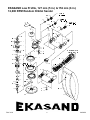
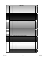
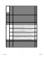
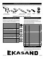
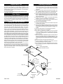
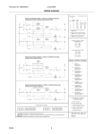
EKASAND Low Profile
127 mm (5 in.) and
152 mm (6 in.) 12,000 RPM
Random Orbital Sander
Features:
•Free Speed of 12,000 Revolutions Per Minute
•Variable Speed Control with Palm Style On/Off Lever
•3 Sizes of Ergonomic Cushion-Grips for comfort and
stability
•Low Profile for Operator Control and Comfort
WARNING
Always wear safety
goggles to protect your
eyes.
OIL DAILY
Oil daily for superior
performance.
EKASAND TOOLS
© EKASAND•0701
•Rear Exhaust Directs Air away from work
•Suggested Applications:
Sanding and Finishing a Variety of Materials including
Wood, Metal, Plastic, Fiberglass Composites, Solid
Surfaces and other Sandable Surfaces
Operators Instructions
Includes – Features and Suggested Applications, Please Read and Comply, Assembly Drawing of Machines, Parts List, Proper Use of Tool, Work
Stations, Putting the Tool Into Service, Operating Instructions, EKASAND
Service Tools and Accessories, EKASAND Back-Up Pads™, EKASAND
Service Kit, EKASAND Warranty
Important
Read these instructions carefully before installing, operating, servicing or
repairing this tool. Keep these instructions in a safe, accessible location.
Please Read and Comply With
1) General Industry Safety & Health Regulations, Part 1910, OSHA 2206,
available from: Superintendent of Documents; Government Printing Office; Washington DC 20402
2) AIR SUPPLY – Test and operate tools at 90 PSIG (6.1 Bar) maximum
unless tool is marked otherwise. Use recommended airline filters regulators – lubricators (FRL).
2) Safety Code for Portable Air Tools, ANSI B186.1 available from: American National Standards Institute, Inc.; 1430 Broadway; New York, NY
10018
3) UNUSUAL SOUND or VIBRATION – If tool vibrates or produces an
unusual sound, repair immediately for correction.
3) State and Local Regulations.
Key parts of the above regulations are excerpted below. They are not intended to be inclusive. Study and comply with all regulations.
1) TOOL INTENT – Tool shall be used only for purposes intended in its
design.
4) OPERATOR PROTECTIVE EQUIPMENT – Wear goggles or face
shield whenever tool is in operation. Other protective clothing shall be
worn, if necessary.
5) SAFETY MAINTENANCE PROGRAM – Employ a safety program to
provide inspection and maintenance of all phases of tool operation and
air supply equipment in accordance with “Safety Code for Portable Air
Tools.”
DOC 1119
04/26/06
EKASAND Low Profile, 127 mm (5 in.) & 152 mm (6 in.)
12,000 RPM Random Orbital Sander
DOC 1119
04/26/06
Parts List
ITEM
P/N
DESCRIPTION
1
ESA0400
RETAINING RING
1
2
ESA1200
BEARING
1
3
ESA5600
REAR ENDPLATE
1
4
ESA4000
PIN (included with item 5)
1
5
ESA7600
CYLINDER ASSEMBLY (includes item 4)
1
6
ESA2400
O-RING
1
7
ESA0100
VANE (5 are included with item 8)
5
8
ESA3600
ROTOR, VANES (Qty. 5) AND KEY SET
1
9
ESA1400
KEY (included in item 8)
1
10
ESA4600
FRONT ENDPLATE
1
11
ESA9100
BEARING
1
12
ESA5400
O-RING
1
13
ESA1000
LOCK RING
1
14
ESB9100
5 mm (3/16 in.) ORBIT SHAFT BALANCER FOR 127 mm (5 in.) PADS
1
ESB0200
5 mm (3/16 in.) ORBIT SHAFT BALANCER FOR 150 mm (6 in.) PADS
ESB7200
2.5 mm (3/32 in.) ORBIT SHAFT BALANCER FOR 127 mm (5 in.) PADS
ESB8200
2.5 mm (3/32 in.) ORBIT SHAFT BALANCER FOR 150 mm (6 in.) PADS
15
ESA7390
SHIM
1
16
ESA8390
BEARING
1
17
ESA6100
SHIM
1
18
ESA7100
WASHER
1
19
ESA8100
RETAINING RING
1
20
ESB8100
SPINDLE
1
21
ESA9750
LEVER FOR 12,000 RPM, 5 mm (3/16 in.) Orbit Machines
1
ESA2850
LEVER FOR 12,000 RPM, 2.5 mm (3/32 in.) Orbit Machines
22
ESA1300
PIN
1
23
ESA3490
65 mm (2 ½ in.) GRIP
OPT
ESA4490
70 mm (2 ¾ in.) GRIP
1
ESA5490
75 mm (3 in.) GRIP
OPT
24
ESA0490
HOUSING
1
25
ESA8000
VALVE STEM ASSEMBLY (includes item 26 O-ring)
1
26
ESA8900
O-RING (included with item 25 Valve Stem Assembly)
1
27
ESA3400
O-RING
1
28
ESB4100
SPEED CONTROL
1
29
ESA9300
RETAINING RING
1
30
ESA6490
127/150 mm (5/6 in.) NON-VAC SHROUD (std on NV machines)
1
31
ESC3700
SuperVAC SHROUD for the following 150 mm (6 in.) pads: Screen Abrasive and LP
1
32
ESC2100
SuperVAC SHROUD for the following 127 mm (5 in.) pads: Delta, TE, LP, Screen
Abrasive and 150 mm (6 in.) TE
1
33
ESA2200
24 mm PAD WRENCH
1
34
2550100
127 mm (5 in.) LP YELLOW NV VINYL PAD
1
2550101
127 mm (5 in.) LP YELLOW NV HOOK PAD
1
2550110
127 mm (5 in.) LP YELLOW VAC VINYL PAD
1
2550111
127 mm (5 in.) LP YELLOW VAC HOOK PAD
1
2550300
127 mm (5 in.) TE YELLOW NV VINYL PAD
1
2550301
127 mm (5 in.) TE YELLOW NV HOOK PAD
1
2550310
127 mm (5 in.) TE YELLOW VAC VINYL PAD
1
2550311
127 mm (5 in.) TE YELLOW VAC HOOK PAD
1
2560100
152 mm (6 in.) LP YELLOW NV VINYL PAD
1
DOC 1119
QTY
04/26/06
34
2560101
152 mm (6 in.) LP YELLOW NV HOOK PAD
1
2560110
152 mm (6 in.) LP YELLOW VAC VINYL PAD
1
2560111
152 mm (6 in.) LP YELLOW VAC HOOK PAD
1
2560300
152 mm (6 in.) TE YELLOW NV VINYL PAD
1
2560301
152 mm (6 in.) TE YELLOW NV HOOK PAD
1
2560310
152 mm (6 in.) TE YELLOW VAC VINYL PAD
1
2560311
152 mm (6 in.) TE YELLOW VAC HOOK PAD
1
35
ESA2600
BRONZE MUFFLER
1
36
ESA8600
MUFFLER
1
37
ESA6610
MUFFLER HOUSING
1
38
ESA9000
SEAT
1
39
ESA7000
VALVE
1
40
ESA4100
VALVE SPRING
1
41
ESA3100
INLET BUSHING
1
42
ESA6000
SGV RETAINER
1
43
ESA4400
O-RING
1
44
ESA8770
Ø 28 mm (1 in.) SuperVAC SGV SEAL (included in item 45)
1
45
ESA2411
Ø 28 mm (1 in.) SuperVAC SGV SWIVEL EXHAUST ASSY (Standard on SGV)
1
46
ESA4580
Ø 19 mm (3/4 in.) SuperVAC SGV SEAl (included in item 47)
OPT
47
ESA0411
Ø 19 mm (3/4 in.) SuperVAC SGV SWIVEL EXHAUST ASSY (Optional on SGV)
OPT
48
ESA2140
Ø 28 mm (1 in.) VAC HOSE TO DOUBLE BAG FITTING AND AIRLINE ASSY (Standard on SGV) INCLUDES: ESA3400 Ø 28 mm (1 in.) x 1.8 m (6 ft.) Vacuum Hose,
ESB3210 Ø 28 mm (1 in.) Hose to Double Bag Vacuum Fitting, ESA3300 Ø 6.3 mm
(1/4 in.) x 1.8 m (6 ft.) Airline with Fittings, ESA2700 Bungee for Ø 6.3 mm (1/4 in.)
Airline & Ø 28 mm (1 in.) Vacuum Hose (5)
1
ESA1140
Ø 19 mm (3/4 in.) VAC HOSE TO DOUBLE BAG FITTING AND AIRLINE ASSY
(Optional on SGV) INCLUDES: ESA0020 Ø 19 mm x 1.5 m (5 ft.) Vacuum Hose,
ESB3310 Ø 19 mm (3/4 in.) Hose to Double Bag Vacuum Fitting, ESA2030 Ø 6.3
mm (1/4 in.) x 1.5 m (5 ft.) Airline with Fittings, ESA1030 Bungee for Ø 6.3 mm (1/4
in.) Airline & Ø 19 mm (3/4 in.) Vacuum Hose (5)
OPT
ESA0030
Ø 19 mm (3/4 in.)VAC HOSE TO Ø 19 mm (3/4 in.) x Ø 28 mm (1 in.) HOSE ADAPTER COUPLING & AIRLINE ASSY INCLUDES: ESA0020 Ø 19 mm (3/4 in.) x 1.5 m
(5 ft.) Vacuum Hose, ESB8800 Ø 19 mm (3/4 in.) Hose to Ø 28 mm (1 in.) Hose
Adapter, ESA2030 Ø 6.3 mm (1/4 in.) x 1.5 m (5 ft.) Airline with Fittings, ESA1030
Bungee for Ø 6.3 mm (1/4 in.) Airline & Ø 19 mm (3/4 in.) Vacuum Hose (5)
OPT
ESA2930
Ø 28 mm (1 in.) VAC HOSE TO Ø 28 mm (1 in.) x Ø 38 mm (1 1/2 in.) FRICTION FIT
ADAPTER & AIRLINE ASSY INCLUDES: ESA4300 Ø 28 mm (1 in.) x 1.8 m (6 ft,)
Vacuum Hose, ESB2900 Ø 28 mm (1 in.) Hose Thread x Ø 38 mm (1 1/2 in.) Friction
Fit Adapter, ESA3300 Ø 6.3 mm (1/4 in.) x 1.8 m (6 ft.) Airline with Fittings, ESA7200
Bungee for Ø 6.3 mm (1/4 in.) Airline & Ø 28 mm (1 in.) Vacuum Hose (5)
OPT
49
ESC8010
SuperVAC SGV SHROUD/SKIRT ADAPTER
1
50
ESA9900
SuperVAC CV Ø 28 mm (1 in.) SWIVEL EXHAUST ASSEMBLY (Standard on CV)
1
51
ESA8400
NUT
1
52
ESA5020
SuperVAC CV Ø 19 mm (3/4 in.) SWIVEL EXHAUST ASSEMBLY (Optional on CV)
OPT
53
ESA7400
WASHER
1
54
ESA9670
SCREW
1
55
ESC0110
VACUUM BAG (Standard on SGV)
1
56
ESC9010
VACUUM BAG INSERT (Standard on SGV)
1
DOC 1119
04/26/06
EKASAND Service Tools and Accessories
When an EKASAND LP ROS needs to be serviced, we offer a tool kit to make the disassembly/assembly fast and easy. The Service Tools are highly recommended for use with the Overhaul Service Kit. NOTICE: To receive any expressed or implied warranty, the tool must be repaired by an authorized EKASAND
Service Center.
T-6 Motor Lock Ring
Wrench/Spindle Puller
T-7 Soft Collar
T-8 Motor Face Plate
Bearing Removal Tool
T-13 Bearing
Press Tool
T-9 Bearing
Puller
T-1 Bearing
Press Tool
ESA9740 Universal Service Tool Kit
EKASAND Back-Up Pads
EKASAND Overhaul Service Kit
EKASAND back-up pads are perfectly mated for use on the
EKASAND LP. Constructed from premium, industrial-quality materials and featuring a riveted fiberglass and steel hub with molded
urethane, their durability and precise construction are the ideal
complement to the performance of the EKASAND LP.
The ESA1311 EKASAND Overhaul Service Kit contains all the replacement parts that naturally wear over time and a straightforward
manual to make servicing an EKASAND sander simple.
Overhauling the Random Orbital Sander can be made even easier
with the use of the above Service Tools. The Service Tools also
reduce the chance of improper assembly.
ESA1311 Overhaul Service Kit Contents
Description
Part#
EKASAND 5” low profile, nv, vinyl face
2550100
EKASAND 5” low profile, nv, hook face
2550101
Item
Part No.
Description
Qty.
EKASAND 5” tapered edge, nv, vinyl face
2550300
1
ESA0400
Retaining Ring
1
EKASAND 5” tapered edge, nv, hook face
2550301
2
ESA1200
Bearing
1
6
ESA2400
O-Ring
1
7
ESA0100
Vane
5
8
ESB5000
Rotor
1
9
ESA1400
Key
1
11
ESA9100
Bearing
1
15
ESA7390
Shim
1
16
ESA8390
Bearing
1
25
ESA8000
Valve Stem Assembly Includes Item 25
1
ESA3400
O-Ring
1
ESA1311 Overhaul Service Kit Contents
EKASAND 5” low profile, vac, vinyl face
2550110
EKASAND 5” low profile, vac, hook face
2550111
EKASAND 5” tapered edge, vac, vinyl face
2550310
EKASAND 5” tapered edge, vac, hook face
2550311
EKASAND 6” low profile, nv, vinyl face
2560100
EKASAND 6” low profile, nv, hook face
2560101
EKASAND 6” tapered edge, nv, vinyl face
2560300
EKASAND 6” tapered edge, nv, hook face
2560301
27
29
ESA9300
Retaining Ring
1
EKASAND 6” low profile, vac, vinyl face
2560110
35
ESA2600
Muffler (for NV and CV Machines)
1
EKASAND 6” low profile, vac, hook face
2560111
36
ESA8600
Muffler
1
EKASAND 6” tapered edge, vac, vinyl face
2560310
37
ESA6610
Muffler Housing
1
EKASAND 6” tapered edge, vac, hook face
2560311
38
ESA9000
Seat
1
39
ESA7000
Valve
1
40
ESA4100
Valve Spring
1
NA
ESA7111
Overhaul Service Manual
1
EKASAND Warranty
All EKASAND Random Orbital Sanders are warranted for defects
in materials or workmanship for 1 year following the date of delivery
to the user. Combined with the EKASAND name, this Warranty expresses our total confidence in the superior quality, durability, and
performance of the EKASAND LP.
DOC 1119
04/26/06
Proper Use of Tool
Operating Instructions
This sander is designed for sanding all types of materials i.e. metals, wood, stone, plastics, etc. using abrasive designed for this
purpose. Do not use this sander for any other purpose than that
specified without consulting the manufacturer or the manufacturer’s authorized supplier.
Do not use back-up pads that have a working speed less than
12,000 RPM free speed.
1) Read all instructions before using this tool. All operators
must be fully trained in its use and aware of these safety
rules. All service and repair must be carried out by trained
personnel.
2) Make sure the tool is disconnected from the air supply. Select a suitable abrasive and secure it to the back-up pad.
Be careful and center the abrasive on the back-up pad.
3) When sanding always place the tool on the work then start
the tool. Always remove the tool from the work before stopping. This will prevent gouging of the work due to excess
speed of the abrasive.
4) Always remove the air supply to the sander before fitting,
adjusting or removing the abrasive or back-up pad.
5) Always adopt a firm footing and/or position and be aware of
torque reaction developed by the sander.
6) Use only correct spare parts.
7) Always ensure that the material to be sanded is firmly fixed
to prevent its movement.
8) Check hose and fittings regularly for wear. Do not carry the
tool by its hose, always be careful to prevent the tool from
being started when carrying the tool with the air supply connected.
9) Do not exceed maximum recommended air pressure.
10)Use safety equipment as recommended.
11) The tool is not electrically insulated. Do not use where
there is a possibility of coming into contact with live electricity, gas pipes, water pipes, etc. Check the area of operation
before operation.
12)Take care to avoid entanglement with the moving parts of
the tool with clothing, ties, hair, cleaning rags, etc. If entangled, it will cause the body to be pulled towards the work
and moving parts of the machine and can be very dangerous.
13)Keep hands clear of the spinning pad during use.
14)If the tool appears to malfunction, remove from use immediately and arrange for service and repair.
15)Do not allow the tool to free speed without taking precautions to protect any persons or objects from the loss of the
abrasive or pad.
Work Station
The tool is intended to be operated as a hand held tool. It is always
recommended that the tool be used when standing on a solid floor.
It can be in any position but before any such use, the operator must
be in a secure position having a firm grip and footing and be aware
that the sander can develop a torque reaction. See the section
“Operating Instructions”.
Putting the Tool into Service
Use a clean lubricated air supply that will give a measured air pressure at the tool of 90 PSI/6.1 Bar when the tool is running with the
lever fully depressed. It is recommended to use an approved 3/8
in./10 mm x 25 ft./8 meter maximum length airline. It is recommended that the tool be connected to the air supply as shown in
Figure 1. Do not connect the tool to the airline system without incorporating an easy to reach and operate air shut off valve. The air
supply should be lubricated. It is strongly recommended that an air
filter, regulator and lubricator (FRL) be used as shown in Figure 1
as this will supply clean, lubricated air at the correct pressure to the
tool. Details of such equipment can be obtained from your supplier.
If such equipment is not used then the tool should be lubricated
by shutting off the air supply to the tool, depressurizing the line by
pressing the lever on the tool. Disconnect the airline and put 2 to
3 drops of a suitable pneumatic motor lubricating oil, preferably incorporating a rust inhibitor into the hose end (inlet) of the machine.
Reconnect tool to air supply and run tool slowly for a few seconds
to allow air to circulate the oil. If tool is used frequently lubricate on
daily basis and if tool starts to slow or lose power.
It is recommended that the air pressure at the tool be 90 PSI/6.1
Bar while the tool is running so the maximum RPM is not exceeded. The tool can be run at lower pressures but should never be run
higher than 90 PSI/6.1 Bars. If run at lower pressure the performance of the tool is reduced.
Closed Loop Pipe System
Sloped in the direction of air flow
Drain Leg
Ball Valve
To Tool Station
Filter
Ball
Valve
Regulator
Lubricator
Ball Valve
Air Flow
Drain Valve
Air Dryer
Air Hose
To Coupler
at or near Tool
Air Compressor
and Tank
Figure 1
DOC 1119
04/26/06