1
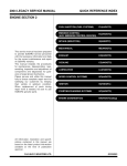
2001 IMPREZA SERVICE MANUAL
QUICK REFERENCE INDEX
ENGINE 2 SECTION
This service manual has been prepared
to provide SUBARU service personnel
with the necessary information and data
for the correct maintenance and repair
of SUBARU vehicles.
This manual includes the procedures
for maintenance, disassembling, reassembling, inspection and adjustment of
components and diagnostics for guidance of experienced mechanics.
Please peruse and utilize this manual
fully to ensure complete repair work for
satisfying our customers by keeping
their vehicle in optimum condition.
When replacement of parts during
repair work is needed, be sure to use
SUBARU genuine parts.
FUEL INJECTION (FUEL SYSTEMS)
FU(SOHCw/oOBD)
EMISSION CONTROL
(AUX. EMISSION CONTROL DEVICES)
EC(SOHCw/oOBD)
EXHAUST
EX(SOHCw/oOBD)
IGNITION
IG(SOHCw/oOBD)
ENGINE(DIAGNOSTICS)
EN(SOHCw/oOBD)
FUEL INJECTION (FUEL SYSTEMS)
FU(DOHC TURBO)
EMISSION CONTROL
(AUX. EMISSION CONTROL DEVICES)
EC(DOHC TURBO)
INTAKE (INDUCTION)
IN(DOHC TURBO)
MECHANICAL
ME(DOHC TURBO)
EXHAUST
EX(DOHC TURBO)
IGNITION
IG(DOHC TURBO)
ENGINE (DIAGNOSTICS)
EN(DOHC TURBO)
All information, illustration and specifications contained in this manual are
based on the latest product information
available at the time of publication
approval.
FUJI HEAVY INDUSTRIES LTD.
G1830GE3
ENGINE (DIAGNOSTICS)
EN(DOHC TURBO)
1.
2.
3.
4.
5.
6.
7.
8.
9.
10.
11.
12.
13.
14.
15.
16.
17.
18.
Page
Basic Diagnostic Procedure ........................................................................2
Check List for Interview...............................................................................3
General Description ....................................................................................5
Electrical Components Location..................................................................8
Engine Control Module (ECM) I/O Signal .................................................20
Engine Condition Data ..............................................................................24
Data Link Connector .................................................................................25
OBD-II General Scan Tool ........................................................................26
Subaru Select Monitor...............................................................................28
Read Diagnostic Trouble Code .................................................................34
Inspection Mode........................................................................................35
Clear Memory Mode..................................................................................38
Compulsory Valve Operation Check Mode ...............................................39
Engine Malfunction Indicator Lamp (MIL) .................................................41
Diagnostics for Engine Starting Failure.....................................................52
List of Diagnostic Trouble Code (DTC) .....................................................69
Diagnostic Procedure with Diagnostic Trouble Code (DTC) .....................74
General Diagnostic Table........................................................................301
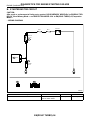
BASIC DIAGNOSTIC PROCEDURE
ENGINE (DIAGNOSTICS)
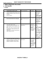
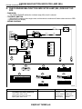
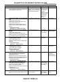
1. Basic Diagnostic Procedure
A: PROCEDURE
1. ENGINE
1
Step
Check
Does the engine start?
CHECK ENGINE START FAILURE.
1)Ask the customer when and how the trouble
occurred using the interview check list. <Ref. to
EN(DOHC TURBO)-3, CHECK, Check List for
Interview.>
2)Start the engine.
2
CHECK ILLUMINATION OF CHECK ENGINE Does CHECK ENGINE malfunction indicator lamp illumiMALFUNCTION INDICATOR LAMP (MIL).
nate?
3
CHECK INDICATION OF DTC ON DISPLAY. Does the Subaru Select Moni1)Turn ignition switch to OFF.
tor or OBD-II general scan tool
indicate DTC?
2)Connect the Subaru Select Monitor or the
OBD-II general scan tool to data link connector.
3)Turn ignition switch to ON and the Subaru
Select Monitor or OBD-II general scan tool
switch to ON.
4)Read DTC on the Subaru Select Monitor or
OBD-II general scan tool.
4
Does the Subaru Select MoniPERFORM THE DIAGNOSIS.
1)Perform the clear memory mode. <Ref. to
tor or OBD-II general scan tool
EN(DOHC TURBO)-38, Clear Memory Mode.> indicate DTC?
2)Perform the inspection mode. <Ref. to
EN(DOHC TURBO)-35, Inspection Mode.>
EN(DOHC TURBO)-2
Yes
Go to step 2.
No
Inspection using
“Diagnostics for
Engine Start Failure”. <Ref. to
EN(DOHC
TURBO)-52, Diagnostics for Engine
Starting Failure.>
Go to step 3.
Inspection using
“General Diagnostics Table”. <Ref.
to EN(DOHC
TURBO)-301,
General Diagnostic Table.>
Record diagnostic Repair the related
parts.
trouble code.
Repair the trouble NOTE:
cause. <Ref. to
If DTC is not
EN(DOHC
shown on display
TURBO)-69, List although the MIL ilof Diagnostic Trou- luminates,
perble Code (DTC).> form diagnostics of
Go to step 4.
MIL (CHECK ENGINE malfunction
indicator lamp) circuit or combination
meter. <Ref. to
EN(DOHC TURBO)-41,
Engine
Malfunction Indicator Lamp (MIL).>
Complete the
Inspect using
“Diagnostics Pro- diagnosis.
cedure with Diagnostic Trouble
Code (DTC)”.
<Ref. to EN(DOHC
TURBO)-74, Diagnostic Procedure
with Diagnostic
Trouble Code
(DTC).>
CHECK LIST FOR INTERVIEW
ENGINE (DIAGNOSTICS)
2. Check List for Interview
Check the following items when problem has occurred.
A: CHECK
NOTE:
Use copies of this page for interviewing customers.
1. CHECK LIST NO. 1
Customer's name
Date of sale
Date of repair
Vin no.
Weather
Engine no.
Fuel brand
Odometer reading
❏ Fine
❏ Cloudy
❏ Rainy
❏ Snowy
❏ Various/Others:
°C (°F)
Outdoor temperature
Place
Engine temperature
Engine speed
Vehicle speed
Driving conditions
Headlight
Blower
A/C compressor
Cooling fan
Front wiper
Rear wiper
km
miles
❏ Hot
❏ Warm
❏ Cool
❏ Cold
❏ Highway
❏ Suburbs
❏ Inner city
❏ Uphill
❏ Downhill
❏ Rough road
❏ Others:
❏ Cold
❏ Warming-up
❏ After warming-up
❏ Any temperature
❏ Others:
rpm
MPH
❏ Not affected
❏ At starting
❏ While idling
❏ At racing
❏ While accelerating
❏ While cruising
❏ While decelerating
❏ While turning (RH/LH)
❏ ON/❏ OFF
❏ ON/❏ OFF
❏ ON/❏ OFF
❏ ON/❏ OFF
❏ ON/❏ OFF
❏ ON/❏ OFF
Rear defogger
Radio
CD/Cassette
Car phone
CB
EN(DOHC TURBO)-3
❏ ON/❏ OFF
❏ ON/❏ OFF
❏ ON/❏ OFF
❏ ON/❏ OFF
❏ ON/❏ OFF
CHECK LIST FOR INTERVIEW
ENGINE (DIAGNOSTICS)
2. CHECK LIST NO. 2
Check the following items about the vehicle's state
when MIL turns on.
NOTE:
Use copies of this page for interviewing customers.
a) Other warning lights or indicators turn on. ❏ Yes/❏ No
❏ Low fuel warning light
❏ Charge indicator light
❏ AT diagnostics indicator light
❏ ABS warning light
❏ Engine oil pressure warning light
b) Fuel level
• Lack of gasoline: ❏ Yes/❏ No
• Indicator position of fuel gauge:
c) Intentional connecting or disconnecting of harness connectors or spark plug cords: ❏ Yes/❏ No
• What:
d) Intentional connecting or disconnecting of hoses: ❏ Yes/❏ No
• What:
e) Installing of parts other than genuine parts: ❏ Yes/❏ No
• What:
• Where:
f) Occurrence of noise: ❏ Yes/❏ No
• From where:
• What kind:
g) Occurrence of smell: ❏ Yes/❏ No
• From where:
• What kind:
h) Intrusion of water into engine compartment or passenger compartment: ❏ Yes/❏ No
i) Troubles occurred
❏ Engine does not start.
❏ Engine stalls during idling.
❏ Engine stalls while driving.
❏ Engine speed decreases.
❏ Engine speed does not decrease.
❏ Rough idling
❏ Poor acceleration
❏ Back fire
❏ After fire
❏ No shift
❏ Excessive shift shock
EN(DOHC TURBO)-4
GENERAL DESCRIPTION
ENGINE (DIAGNOSTICS)
3. General Description
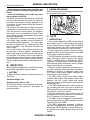
8) Use ECM mounting stud bolts at the body head
grounding point when measuring voltage and resistance inside the passenger compartment.
A: CAUTION
1) Airbag system wiring harness is routed near the
engine control module (ECM), main relay and fuel
pump relay.
CAUTION:
• All Airbag system wiring harness and connectors are colored yellow. Do not use electrical test equipment on these circuit.
• Be careful not to damage Airbag system wiring harness when servicing the engine control
module (ECM), transmission control module
(TCM), main relay and fuel pump relay.
2) Never connect the battery in reverse polarity.
• The ECM will be destroyed instantly.
• The fuel injector and other part will be damaged
in just a few minutes more.
3) Do not disconnect the battery terminals while the
engine is running.
• A large counter electromotive force will be generated in the alternator, and this voltage may damage
electronic parts such as ECM, etc.
4) Before disconnecting the connectors of each
sensor and the ECM, be sure to turn OFF the ignition switch.
5) Poor contact has been identified as a primary
cause of this problem. To measure the voltage and/
or resistance of individual sensors or all electrical
control modules at the harness side connector, use
a tapered pin with a diameter of less than 0.64 mm
(0.025 in). Do not insert the pin more than 5 mm
(0.20 in) into the part.
6) Before removing ECM from the located position,
disconnect two cables on battery.
• Otherwise, the ECM may be damaged.
CAUTION:
When replacing ECM, be careful not to use the
wrong spec. ECM to avoid any damage on fuel
injection system.
7) The connectors to each sensor in the engine
compartment and the harness connectors on the
engine side and body side are all designed to be
waterproof. However, it is still necessary to take
care not to allow water to get into the connectors
when washing the vehicle, or when servicing the
vehicle on a rainy day.
H2M1154A
9) Use engine grounding terminal or engine proper
as the grounding point to the body when measuring
voltage and resistance in the engine compartment.
EN0945
10) Use TCM mounting stud bolts at the body head
grounding point when measuring voltage and resistance inside the passenger compartment.
B3M1666E
11) Every MFI-related part is a precision part. Do
not drop them.
12) Observe the following cautions when installing
a radio in MFI equipped models.
CAUTION:
• The antenna must be kept as far apart as possible from the control unit.
(The ECM is located under the steering column,
inside of the instrument panel lower trim panel.)
• The antenna feeder must be placed as far
apart as possible from the ECM and MFI harness.
• Carefully adjust the antenna for correct
matching.
EN(DOHC TURBO)-5
GENERAL DESCRIPTION
ENGINE (DIAGNOSTICS)
• When mounting a large power type radio, pay
special attention to the three items above mentioned.
• Incorrect installation of the radio may affect
the operation of the ECM.
13) Before disconnecting the fuel hose, disconnect
the fuel pump connector and crank the engine for
more than five seconds to release pressure in the
fuel system. If engine starts during this operation,
run it until it stops.
14) Problems in the electronic-controlled automatic
transmission may be caused by failure of the engine, the electronic control system, the transmission proper, or by a combination of these. These
three causes must be distinguished clearly when
performing diagnostics.
15) Diagnostics should be conducted by rotating
with simple, easy operations and proceeding to
complicated, difficult operations. The most important thing in diagnostics is to understand the customer's complaint, and distinguish between the
three causes.
16) On ABS vehicle, when performing driving test
in jacked-up or lifted-up position, sometimes the
warning light may be lit, but this is not a malfunction
of the system. The reason for this is the speed difference between the front and rear wheels. After diagnosis of engine control system, perform the ABS
memory clearance procedure of self-diagnosis system.
B: INSPECTION
Before performing diagnostics, check the following
items which might affect engine problems:
1. BATTERY
1) Measure battery voltage and specific gravity of
electrolyte.
Standard voltage: 12 V
Specific gravity: Above 1.260
2) Check the condition of the main and other fuses,
and harnesses and connectors. Also check for
proper grounding.
2. ENGINE GROUNDING
Make sure the engine grounding terminal is properly connected to the engine.
EN0945
C: NOTE
1. DESCRIPTION
• The on-board diagnostics (OBD) system detects
and indicates a fault in various inputs and outputs
of the complex electronic control. CHECK ENGINE
malfunction indicator lamp (MIL) in the combination
meter indicates occurrence of a fault or trouble.
• Further, against such a failure or sensors as may
disable the drive, the fail-safe function is provided
to ensure the minimal driveability.
• The OBD system incorporated with the vehicles
within this engine family complies with Section
1968.1, California Code of Regulations (OBD-II
regulation). The OBD system monitors the components and the system malfunction listed in Engine
Section which affects on emissions.
• When the system decides that a malfunction occurs, MIL illuminates. At the same time of the MIL illumination or blinking, a diagnostic trouble code
(DTC) and a freeze frame engine conditions are
stored into on-board computer.
• The OBD system stores freeze frame engine
condition data (engine load, engine coolant temperature, fuel trim, engine speed and vehicle
speed, etc.) into on-board computer when it detects
a malfunction first.
• If the OBD system detects the various malfunctions including the fault of fuel trim or misfire, the
OBD system first stores freeze frame engine conditions about the fuel trim or misfire.
• When the malfunction does not occur again for
three consecutive driving cycles, MIL is turned off,
but DTC remains at on-board computer.
• The OBD-II system is capable of communication
with a general scan tool (OBD-II general scan tool)
formed by ISO 9141 CARB.
• The OBD-II diagnostics procedure is different
from the usual diagnostics procedure. When troubleshooting OBD-II vehicles, connect Subaru Select Monitor or the OBD-II general scan tool to the
vehicle.
EN(DOHC TURBO)-6
GENERAL DESCRIPTION
ENGINE (DIAGNOSTICS)
2. ENGINE AND EMISSION CONTROL SYSTEM
• The Multipoint Fuel Injection (MFI) system is a
system that supplies the optimum air-fuel mixture
to the engine for all the various operating conditions through the use of the latest electronic technology.
With this system fuel, which is pressurized at a constant pressure, is injected into the intake air passage of the cylinder head. The injection quantity of
fuel is controlled by an intermittent injection system
where the electro-magnetic injection valve (fuel injector) opens only for a short period of time, depending on the quantity of air required for one cycle
of operation. In actual operation, the injection quantity is determined by the duration of an electric
pulse applied to the fuel injector and this permits
simple, yet highly precise metering of the fuel.
• Further, all the operating conditions of the engine
are converted into electric signals, and this results
in additional features of the system, such as large
improved adaptability, easier addition of compensating element, etc.
The MFI system also has the following features:
• Reduced emission of harmful exhaust gases.
• Reduced in fuel consumption.
• Increased engine output.
• Superior acceleration and deceleration.
• Superior startability and warm-up performance in cold weather since compensation is
made for coolant and intake air temperature.
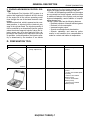
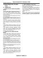
D: PREPARATION TOOL
ILLUSTRATION
TOOL NUMBER
24082AA150
(Newly adapted tool)
DESCRIPTION
CARTRIDGE
REMARKS
Troubleshooting for electrical
systems.
22771AA030
SELECT MONITOR KIT
Troubleshooting for electrical
systems.
• English: 22771AA030 (Without printer)
• German: 22771AA070
(Without printer)
• French: 22771AA080
(Without printer)
• Spanish: 22771AA090
(Without printer)
B2M3876
B2M3877
EN(DOHC TURBO)-7
ELECTRICAL COMPONENTS LOCATION
ENGINE (DIAGNOSTICS)
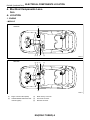
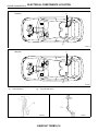
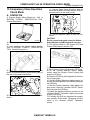
4. Electrical Components Location
A: LOCATION
1. ENGINE
• MODULE
LHD model
(1)
(3) (4) (2)
(5)
EN0713
RHD model
(3) (4) (2)
(5)
(1)
EN0714
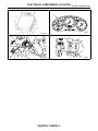
(1)
(2)
Engine control module (ECM)
CHECK ENGINE malfunction indicator lamp (MIL)
(3)
(4)
(5)
Read memory connector
Test mode connector
Data link connector
EN(DOHC TURBO)-8
ELECTRICAL COMPONENTS LOCATION
ENGINE (DIAGNOSTICS)
(2)
EN0718
B3M1575A
(3)
EN0716
EN(DOHC TURBO)-9
(5)
EN0717
ELECTRICAL COMPONENTS LOCATION
ENGINE (DIAGNOSTICS)
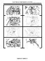
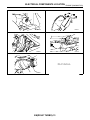
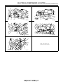
• SENSOR
(7)
(8)
(2)
(1)
(3)
(6)
(4)
(8)
(5)
EN0946
(1)
(2)
Pressure sensor
Engine coolant temperature sensor
(3)
Throttle position sensor
(4)
(5)
(6)
(7)
Knock sensor
Camshaft position sensor
Crankshaft position sensor
Mass air flow and intake air temperature sensor
EN(DOHC TURBO)-10
(8)
Tumble generator valve position
sensor
ELECTRICAL COMPONENTS LOCATION
ENGINE (DIAGNOSTICS)
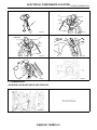
(2)
(1)
EN1008
EN1009
EN1010
EN1011
EN1012
EN1013
(3)
(8)
(7)
EN1014
EN(DOHC TURBO)-11
EN1015
ELECTRICAL COMPONENTS LOCATION
ENGINE (DIAGNOSTICS)
(1)
(2)
(3)
(4)
(5)
(6)
EN0948
(1)
(2)
Front oxygen (A/F) sensor
Precatalytic converter
(3)
(4)
Exhaust temperature sensor
Front catalytic converter
EN(DOHC TURBO)-12
(5)
(6)
Rear oxygen sensor
Rear catalytic converter
ELECTRICAL COMPONENTS LOCATION
ENGINE (DIAGNOSTICS)
(1)
(3)
(2)
EN1016
EN1017
(5)
(4)
EN0949
(6)
EN0950
EN(DOHC TURBO)-13
EN1018
ELECTRICAL COMPONENTS LOCATION
ENGINE (DIAGNOSTICS)
LHD model
(1)
(2)
EN1019
RHD model
(1)
(2)
EN1020
(1)
Fuel level sensor
(2)
Fuel sub level sensor
EN1036
EN(DOHC TURBO)-14
EN1037
ELECTRICAL COMPONENTS LOCATION
ENGINE (DIAGNOSTICS)
EN(DOHC TURBO)-15
ELECTRICAL COMPONENTS LOCATION
ENGINE (DIAGNOSTICS)
• SOLENOID VALVE, ACTUATOR, EMISSION CONTROL SYSTEM PARTS AND IGNITION SYSTEM
PARTS
(1)
(2)
(5)
(3)
(5)
(4)
EN0951
(1)
(2)
Wastegate control solenoid valve
Idle air control solenoid valve
(3)
(4)
Purge control solenoid valve
Ignition coil
EN(DOHC TURBO)-16
(5)
Tumble generator valve actuator
ELECTRICAL COMPONENTS LOCATION
ENGINE (DIAGNOSTICS)
(2)
(1)
EN1021
EN1022
(3)
(4)
EN1023
(5)
EN0952
EN(DOHC TURBO)-17
EN1024
ELECTRICAL COMPONENTS LOCATION
ENGINE (DIAGNOSTICS)
LHD model
(2)
(3)
(1)
(4)
(5) (6) (7) (8) (9)
EN1025
RHD model
(1)
(5) (6) (7) (8) (9)
(2)
(4)
(3)
EN1026
(1)
(2)
(3)
Fuel pump
Main relay
Fuel pump relay
(4)
(5)
(6)
Fuel pump controller
Radiator main fan relay 1
Radiator main fan relay 2
EN(DOHC TURBO)-18
(7)
(8)
(9)
Radiator sub fan relay 1
Radiator sub fan relay 2
Starter
ELECTRICAL COMPONENTS LOCATION
ENGINE (DIAGNOSTICS)
LHD model
(2)
(3)
(1)
EN0953
RHD model
EN1027
(2)
(3)
(4)
EN1028
EN1029
EN0954
EN1030
(5)
(6)
(7)
(8)
2. TRANSMISSION
• SOLENOID VALVE AND SWITCH (MT VEHICLES)
B2M2265A
(1) Neutral position switch
EN(DOHC TURBO)-19
ENGINE CONTROL MODULE (ECM) I/O SIGNAL
ENGINE (DIAGNOSTICS)
5. Engine Control Module (ECM) I/O Signal
A: ELECTRICAL SPECIFICATION
To
To
B134
B135
To
9 8 7
6 5 4 3 2 1
19 18 17 16 15 14 13 12 11 10
28 27 26 25 24 23
22 21 20
7 6
5 4 3 2 1
15 14 13 12 11 10 9 8
22 21 20 19 18
17 16
To
2 1
7 6 5 4 3
16 15 14 13 12 11 10 9 8
21 20 19 18 17
24 23 22
To
B137
9 8 7 6 4 5 3
2 1
21 20 19 18 17 16 15 14 13 12 11 10
31 30 29
28 27
26 25 24 23 22
B136
B84
6 5 4 3 2 1
12 11 10 9 8 7
17 16
15 14 13
EN0955
Signal (V)
Ignition SW ON
Engine ON (Idling)
(Engine OFF)
0
−7 — +7
0
0
0
0
0
−7 — +7
0
0
0
0
Fully closed: 0.2 — 1.0
Fully opened: 4.2 — 4.7
Content
Connector
No.
Terminal No.
Signal (+)
Crankshaft posi- Signal (−)
tion sensor Shield
Camshaft Signal (+)
position
Signal (−)
sensor
Shield
B135
B135
B135
B135
B135
B135
2
11
21
1
10
21
B135
7
B135
9
5
5
—
B135
19
0
0
—
B135
B135
17
26
0
0
0 — 0.9
0
—
—
B135
19
0
0
—
B137
4
0 — 1.0
0 — 1.0
—
B137
5
0 — 1.0
0 — 1.0
—
B136
13
0 — 1.0
0 — 1.0
—
B135
18
1.0 — 1.4
1.0 — 1.4
After warm-up the engine.
B135
19
0
0
After warm-up the engine.
B134
1
0 or 5
0 or 5
Signal
Throttle
position
sensor
Rear oxygen sensor
Power
supply
GND (sensor)
Signal
Shield
GND (sensor)
Signal 1
Front oxygen (A/F)
sensor
Signal 2
heater
Rear oxygen sensor
heater signal
Engine
Signal
coolant
temperaGND (senture sensor)
sor
Vehicle speed signal
EN(DOHC TURBO)-20
Note
Sensor output waveform
—
—
Sensor output waveform
—
—
—
“5” and “0” are repeatedly displayed when vehicle is driven.
ENGINE CONTROL MODULE (ECM) I/O SIGNAL
ENGINE (DIAGNOSTICS)
Content
Signal
Shield
GND
Intake air temperature
sensor signal
Exhaust
Signal
gas temGND
perature
(sensor)
sensor
Signal (V)
Connector
No.
Terminal No.
B84
B84
B84
13
8
7
Ignition SW ON
(Engine OFF)
—
0
0
B135
27
B135
Engine ON (Idling)
Note
0.3 — 4.5
0
0
—
—
—
—
—
—
16
—
—
—
B135
19
0
0
—
B84
23
B135
9
5
5
—
B135
19
0
0
—
B84
13
B135
9
5
5
—
B135
19
0
0
—
B84
4
0 or 5
0 or 5
—
B84
5
0 or 5
0 or 5
—
B84
11
0 or 5
0 or 5
—
B84
10
0 or 5
0 or 5
—
B137
24
10 — 13
13 — 14
—
B134
16
A/C switch
B134
6
Ignition switch
B134
14
0
ON: 10 — 13
OFF: 0
10 — 13
0
ON: 13 — 14
OFF: 0
13 — 14
Mass air
flow sensor
Tumble
generator
valve position sensor
RH
Signal
Tumble
generator
valve position sensor
LH
Signal
Power
supply
GND
(sensor)
Power
supply
GND
(sensor)
Tumble generator valve
RH (open)
Tumble generator valve
RH (close)
Tumble generator valve
LH (open)
Tumble generator valve
LH (close)
Wastegate control solenoid valve
Starter switch
Neutral position switch
B134
8
Test mode connector
Signal
Knock
sensor
Shield
Back-up power supply
B134
B135
B135
B137
B137
B137
B135
B134
B136
B136
B136
B136
5
4
22
10
2
3
9
10
24
23
22
21
Control unit power supply
Sensor power supply
Line end check 1
#1
#2
Ignition
control
#3
#4
Fully closed: 0.2 — 1.0
Fully opened: 4.2 — 4.7
—
Fully closed: 0.2 — 1.0
Fully opened: 4.2 — 4.7
—
ON: 12±0.5
OFF: 0
5
2.8
0
10 — 13
10 — 13
10 — 13
5
0
0
0
0
0
5
2.8
0
13 — 14
13 — 14
13 — 14
5
0
13 — 14
13 — 14
13 — 14
13 — 14
EN(DOHC TURBO)-21
Cranking: 8 — 14
—
—
Switch is ON when gear is in
neutral position.
When connected: 0
—
—
Ignition switch “OFF”: 10 — 13
—
—
—
—
Waveform
Waveform
Waveform
Waveform
ENGINE CONTROL MODULE (ECM) I/O SIGNAL
ENGINE (DIAGNOSTICS)
Signal (V)
Content
Connector
No.
Terminal No.
Fuel injector
#1
#2
#3
#4
B137
B136
B136
B136
1
6
5
4
Ignition SW ON
(Engine OFF)
10 — 13
10 — 13
10 — 13
10 — 13
Idle air
control
solenoid
valve
Signal
B136
10
Fuel pump
controller
Signal 1
Signal 2
B134
B136
13
16
B137
27
B137
17
B137
28
B137
Engine ON (Idling)
Note
1 — 14
1 — 14
1 — 14
1 — 14
Waveform
Waveform
Waveform
Waveform
0 or 13 — 14
0 or 13 — 14
Waveform
—
—
ON: 0.5, or less
OFF: 10 — 13
ON: 0.5, or less
OFF: 10 — 13
ON: 0.5, or less
OFF: 10 — 13
—
—
ON: 0.5, or less
OFF: 13 — 14
ON: 0.5, or less
OFF: 13 — 14
ON: 0.5, or less
OFF: 13 — 14
—
—
15
—
—
B136
9
B137
16
B135
8
—
ON: 1, or less
OFF: 10 — 13
1.7 — 2.4
0 — 13, or more
ON: 1, or less
OFF: 13 — 14
1.1 — 1.6
B135
9
5
5
B135
19
0
0
B135
25
Small light switch
B134
17
Blower fan switch
B134
9
Rear defogger switch
B134
3
0.12 — 4.75
ON: 0
OFF: 10 — 13
ON: 0
OFF: 10 — 13
ON: 0
OFF: 10 — 13
B135
24
10 — 13
0.12 — 4.75
ON: 0
OFF: 13 — 14
ON: 0
OFF: 13 — 14
ON: 0
OFF: 13 — 14
ON: 0
OFF: 13 — 14
B137
19
2.8 — 3.2
2.8 — 3.2
—
B137
29
2.4 — 2.7
2.4 — 2.7
—
B136
7
0
0
—
B134
21
B135
B136
B136
B136
B134
B134
B134
19
8
18
17
22
7
15
Less than 1 ←→ More
than 4
0
0
0
0
0
0
0
Less than 1 ←→ More
than 4
0
0
0
0
0
0
0
A/C relay control
Radiator fan relay 1
control
Radiator fan relay 2
control
Malfunction indicator
lamp
Engine speed output
Purge control solenoid
valve
Signal
Power
pressure
supply
sensor
GND (sensor)
Fuel level sensor
Power steering oil pressure switch
Front oxygen (A/F) sensor signal (+)
Front oxygen (A/F) sensor signal (−)
Front oxygen (A/F) sensor shield
SSM/GST communication line
GND (sensors)
GND (injectors)
GND (ignition system)
GND (power supply)
GND (control systems)
EN(DOHC TURBO)-22
—
—
With A/C vehicles only
Light “ON”: 1, or less
Light “OFF”: 10 — 14
Waveform
—
—
—
—
—
—
—
—
—
—
—
—
—
—
—
ENGINE CONTROL MODULE (ECM) I/O SIGNAL
ENGINE (DIAGNOSTICS)
Content
GND (oxygen sensor
heater 1)
GND (oxygen sensor
heater 2)
Connector
No.
Terminal No.
B137
B137
Signal (V)
Note
Ignition SW ON
(Engine OFF)
Engine ON (Idling)
9
0
0
—
8
0
0
—
EN(DOHC TURBO)-23
ENGINE CONDITION DATA
ENGINE (DIAGNOSTICS)
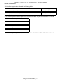
6. Engine Condition Data
A: ELECTRICAL SPECIFICATION
Content
Specified data
1.6 — 2.9 (%): Idling
6.4 — 12.8 (%): 2,500 rpm racing
Engine load
Measuring condition:
• After warm-up the engine.
• Gear position is in neutral position.
• A/C is turned OFF.
• All accessory switches are turned OFF.
EN(DOHC TURBO)-24
DATA LINK CONNECTOR
ENGINE (DIAGNOSTICS)
7. Data Link Connector
A: NOTE
1) This connector is used both for OBD-II general scan tools and the Subaru Select Monitor.
2) Terminal No. 4 to No. 6 of the data link connector is used for the Subaru Select Monitor signal.
CAUTION:
Do not connect any scan tools other than the OBD-II general scan tools and the Subaru Select Monitor, because the circuit for the Subaru Select Monitor may be damaged.
H2M1280
Terminal No.
1
2
3
4
5
6
7
8
Contents
Power supply
Blank
Blank
Subaru Select Monitor signal (ECM to Subaru
Select Monitor)*
Subaru Select Monitor signal (Subaru Select
Monitor to ECM)*
Line end check signal 1
Blank
Blank
Terminal No.
9
10
11
Contents
Blank
K line of ISO 9141 CARB
Blank
12
Ground
13
Ground
14
15
16
Blank
Blank
Blank
*: Circuit only for Subaru Select Monitor
EN(DOHC TURBO)-25
OBD-II GENERAL SCAN TOOL
ENGINE (DIAGNOSTICS)
8. OBD-II General Scan Tool
A: OPERATION
1. HOW TO USE OBD-II GENERAL SCAN
TOOL
1) Prepare a general scan tool (OBD-II general
scan tool) required by SAE J1978.
2) Open the cover and connect the OBD-II general
scan tool to the data link connector located in the
lower portion of the instrument panel (on the driver's side).
3) Using the OBD-II general scan tool, call up diagnostic trouble code(s) and freeze frame data.
OBD-II general scan tool functions consist of:
(1) MODE $01: Current powertrain diagnostic
data
(2) MODE $02: Powertrain freeze frame data
(3) MODE $03: Emission-related powertrain diagnostic trouble codes
(4) MODE $04: Clear/Reset emission-related
diagnostic information
Read out data according to repair procedures. (For
detailed operation procedures, refer to the OBD-II
General Scan Tool Operation Manual.)
NOTE:
For details concerning diagnostic trouble codes, refer to the List of Diagnostic Trouble Code (DTC).
<Ref. to EN(DOHC TURBO)-69, List of Diagnostic
Trouble Code (DTC).>
EN0768
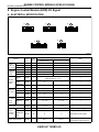
2. MODE $01 (CURRENT POWERTRAIN DIAGNOSTIC DATA)
Refers to data denoting the current operating condition of analog input/output, digital input/output and/or the
powertrain system.
A list of the support data and PID (Parameter Identification) codes are shown in the following table.
PID
01
03
04
05
06
07
0B
0C
0D
0E
0F
10
11
13
15
24
1C
Data
Number of emission-related powertrain trouble codes and MIL status
Fuel system control status
Calculated engine load value
Engine coolant temperature
Short term fuel trim
Long term fuel trim
Intake manifold absolute pressure
Engine revolution
Vehicle speed
Ignition timing advance
Intake air temperature
Air flow rate from pressure sensor
Throttle valve opening angle
Check whether oxygen sensor is installed.
Oxygen sensor output voltage and short term fuel trim associated with oxygen sensor—bank
2
A/F sensor 1 output voltage and short term fuel trim associated with A/F sensor 1
On-board diagnosis system
Unit of measure
ON/OFF
—
%
°C
%
%
kPa
rpm
km/h
°
°C
g/sec
%
—
V and %
V and %
—
NOTE:
Refer to OBD-II general scan tool manufacturer's instruction manual to access generic OBD-II PIDs (MODE
$01).
EN(DOHC TURBO)-26
OBD-II GENERAL SCAN TOOL
ENGINE (DIAGNOSTICS)
3. MODE $02 (POWERTRAIN FREEZE FRAME DATA)
Refers to data denoting the operating condition when trouble is sensed by the on-board diagnosis system.
A list of the support data and PID (Parameter Identification) codes are shown in the following table.
PID
02
03
04
05
06
07
0B
0C
0D
Data
Trouble code that caused CARB required freeze frame data storage
Fuel system control status
Calculated engine load value
Engine coolant temperature
Short term fuel trim
Long term fuel trim
Intake manifold absolute pressure
Engine revolution
Vehicle speed
Unit of measure
—
—
%
°C
%
%
kPa
rpm
km/h
NOTE:
Refer to OBD-II general scan tool manufacturer's instruction manual to access freeze frame data (MODE
$02).
4. MODE $03 (EMISSION-RELATED POWERTRAIN DIAGNOSTIC TROUBLE CODE)
Refer to Read Diagnostic Trouble Code for information about data denoting emission-related powertrain diagnostic trouble codes. <Ref. to EN(DOHC TURBO)-34, Read Diagnostic Trouble Code.>
5. MODE $04 (CLEAR/RESET EMISSION-RELATED DIAGNOSTIC INFORMATION)
Refers to the mode used to clear or reset emission-related diagnostic information (OBD-II trouble diagnostic
information).
NOTE:
Refer to OBD-II general scan tool manufacturer's instruction manual to clear or reset emission-related diagnostic information (MODE $04).
EN(DOHC TURBO)-27
SUBARU SELECT MONITOR
ENGINE (DIAGNOSTICS)
9. Subaru Select Monitor
5) Turn ignition switch to ON (engine OFF) and
Subaru Select Monitor switch to ON.
A: OPERATION
1. HOW TO USE SUBARU SELECT MONITOR
1) Prepare Subaru Select Monitor kit. <Ref. to
EN(DOHC TURBO)-7, PREPARATION TOOL,
General Description.>
S2M0288A
6) Using Subaru Select Monitor, call up diagnostic
trouble code(s) and various data, then record them.
2. READ DIAGNOSTIC TROUBLE CODE
(DTC) FOR ENGINE. (NORMAL MODE)
S2M0285
2) Connect diagnosis cable to Subaru Select Monitor.
3) Insert cartridge into Subaru Select Monitor.
<Ref. to EN(DOHC TURBO)-7, PREPARATION
TOOL, General Description.>
Refer to Read Diagnostic Trouble Code for information about how to indicate DTC. <Ref. to
EN(DOHC TURBO)-34, Read Diagnostic Trouble
Code.>
3. READ DIAGNOSTIC TROUBLE CODE
(DTC) FOR ENGINE. (OBD MODE)
Refer to Read Diagnostic Trouble Code for information about how to indicate DTC. <Ref. to
EN(DOHC TURBO)-34, Read Diagnostic Trouble
Code.>
S2M0286A
4) Connect Subaru Select Monitor to data link connector.
(1) Data link connector located in the lower portion of the instrument panel (on the driver's
side).
EN0768
(2) Connect diagnosis cable to data link connector.
CAUTION:
Do not connect scan tools except for Subaru
Select Monitor and OBD-II general scan tool.
EN(DOHC TURBO)-28
SUBARU SELECT MONITOR
ENGINE (DIAGNOSTICS)
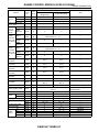
4. READ CURRENT DATA FOR ENGINE. (NORMAL MODE)
1) On the «Main Menu» display screen, select the {Each System Check} and press the [YES] key.
2) On the «System Selection Menu» display screen, select the {Engine Control System} and press the [YES]
key.
3) Press the [YES] key after displayed the information of engine type.
4) On the «Engine Diagnosis» display screen, select the {Current Data Display & Save} and press the [YES]
key.
5) On the «Data Display Menu» display screen, select the {Data Display} and press the [YES] key.
6) Using the scroll key, move the display screen up or down until the desired data is shown.
• A list of the support data is shown in the following table.
Contents
Battery voltage
Vehicle speed signal
Engine speed signal
Engine coolant temperature signal
Ignition timing signal
Throttle position signal
Throttle position signal
Injection pulse width
Idle air control signal
Alternator duty control signal
Fuel pump duty control signal
A/F sensor current
A/F sensor resistance
Front oxygen (A/F) sensor output signal
Rear oxygen sensor output signal
Short term fuel trim
Knock sensor signal
Display
Battery Voltage
Vehicle Speed
Engine Speed
Coolant Temp.
Ignition Timing
Throttle Opening Angle
Throttle Sensor Voltage
Fuel Injection #1 Pulse
ISC Valve Duty Ratio
ALT Duty
Fuel Pump Duty
A/F Sensor #1 Current
A/F Sensor #1 Resistance
A/F Sensor #1
Rear O2 Sensor
A/F Correction #1
Knocking Correction
Atmospheric absolute pressure signal
Atmosphere Pressure
Intake manifold relative pressure signal
Mani. Relative Pressure
Intake manifold absolute pressure signal
Mani. Absolute Pressure
A/F correction (short term fuel trim) by rear oxygen sensor
Long term whole fuel trim
Front oxygen (A/F) sensor heater current
Rear oxygen sensor heater voltage
Canister purge control solenoid valve duty ratio
Primary supercharged pressure control signal
Tumble generator valve position sensor signal (right side)
Tumble generator valve position sensor signal (left side)
Tumble generator valve drive signal
Fuel level signal
Intake air temperature signal
Learned ignition timing
Mass air flow sensor signal
Mass air flow sensor signal
Ignition switch signal
Test mode connector signal
Neutral position switch signal
Air conditioning switch signal
Air conditioning signal
A/F Correction #3
A/F Learning #1
A/F Heater Current 1
Rear O2 Heater Voltage
CPC Valve Duty Ratio
Primary Control
TGV Position Sensor R
TGV Position Sensor L
TGV Drive
Fuel Level
Intake Air Temp.
Learned Ignition Timing
Mass Air Flow
Air Flow Sensor Voltage
Ignition Switch
Test Mode Signal
Neutral Position Switch
A/C Switch
A/C Compressor Signal
EN(DOHC TURBO)-29
Unit of measure
V
km/h or MPH
rpm
°C or °F
deg
%
V
ms
%
%
%
mA
Ω
—
V
%
deg
mmHg or kPa or inHg or
psi
mmHg or kPa or inHg or
psi
mmHg or kPa or inHg or
psi
%
%
A
V
%
%
V
V
OPEN or CLOSE
V
°C or °F
deg
g/s
V
ON or OFF
ON or OFF
ON or OFF
ON or OFF
ON or OFF
SUBARU SELECT MONITOR
ENGINE (DIAGNOSTICS)
Contents
Radiator main fan relay signal
Fuel pump relay signal
Knocking signal
Radiator sub fan relay signal
Power steering switch signal
Engine torque control signal #1
Engine torque control signal #2
Engine torque control permission signal
Rear oxygen sensor rich signal
Starter switch signal
Idle switch signal
Crankshaft position sensor signal
Camshaft position sensor signal
Rear defogger switch signal
Blower fan switch signal
Small light switch signal
Tumble generator valve output signal
Display
Radiator Fan Relay #1
Fuel Pump Relay
Knocking Signal
Radiator Fan Relay #2
P/S Switch
Torque Control Signal #1
Torque Control Signal #2
Torque Permission Signal
Rear O2 Rich Signal
Starter Switch
Idle Switch
Crankshaft Position Sig.
Camshaft Position Sig.
Rear Defogger SW
Blower Fan SW
Light Switch
TGV Output
Unit of measure
ON or OFF
ON or OFF
ON or OFF
ON or OFF
ON or OFF
ON or OFF
ON or OFF
ON or OFF
ON or OFF
ON or OFF
ON or OFF
ON or OFF
ON or OFF
ON or OFF
ON or OFF
ON or OFF
ON or OFF
NOTE:
For detailed operation procedure, refer to the SUBARU SELECT MONITOR OPERATION MANUAL.
EN(DOHC TURBO)-30
SUBARU SELECT MONITOR
ENGINE (DIAGNOSTICS)
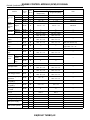
5. READ CURRENT DATA FOR ENGINE. (OBD MODE)
1) On the «Main Menu» display screen, select the {Each System Check} and press the [YES] key.
2) On the «System Selection Menu» display screen, select the {Engine Control System} and press the [YES]
key.
3) Press the [YES] key after displayed the information of engine type.
4) On the «Engine Diagnosis» display screen, select the {OBD System} and press the [YES] key.
5) On the «OBD Menu» display screen, select the {Current Data Display & Save} and press the [YES] key.
6) On the «Data Display Menu» display screen, select the {Data Display} and press the [YES] key.
7) Using the scroll key, move the display screen up or down until the desired data is shown.
• A list of the support data is shown in the following table.
Contents
Number of diagnosis code
Malfunction indicator lamp status
Monitoring test of misfire
Monitoring test of fuel system
Monitoring test of comprehensive component
Test of catalyst
Test of heated catalyst
Test of evaporative emission purge control system
Test of secondary air system
Test of air conditioning system refrigerant
Test of oxygen sensor
Test of oxygen sensor heater
Test of EGR system
Air fuel ratio control system for bank 1
Engine load data
Engine coolant temperature signal
Short term fuel trim by front oxygen (A/F) sensor
Long term fuel trim by front oxygen (A/F) sensor
Display
Number of Diagnosis Code
MI (MIL)
Misfire monitoring
Fuel system monitoring
Component monitoring
Catalyst Diagnosis
Heated catalyst
Evaporative purge system
Secondary air system
A/C system refrigerant
Oxygen sensor
O2 Heater Diagnosis
EGR system
Fuel System for Bank 1
Calculated load value
Coolant Temp.
Short term fuel trim B1
Long term fuel trim B1
Intake manifold absolute pressure signal
Mani. Absolute Pressure
Engine speed signal
Vehicle speed signal
Ignition timing advance for #1 cylinder
Intake air temperature signal
Intake air amount
Throttle position signal
A/F sensor equipment
Rear oxygen sensor output signal
Air fuel ratio correction by rear oxygen sensor
On-board diagnostic system
Engine Speed
Vehicle Speed
Ignition timing adv. #1
Intake Air Temp.
Mass Air Flow
Throttle Opening Angle
A/F sensor
Oxygen Sensor #12
Short term fuel trim #12
OBD System
Unit of measure
—
Complete or incomplete
Complete or incomplete
Complete or incomplete
Complete or incomplete
No support
No support
No support
No support
No support
Complete or incomplete
Complete or incomplete
No support
—
%
°C or °F
%
%
mmHg or kPa or inHg or
psi
rpm
km/h or MPH
°
°C or °F
g/s
%
ON or OFF
V
%
—
NOTE:
For detailed operation procedure, refer to the SUBARU SELECT MONITOR OPERATION MANUAL.
EN(DOHC TURBO)-31
SUBARU SELECT MONITOR
ENGINE (DIAGNOSTICS)
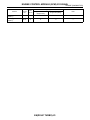
6. READ FREEZE FRAME DATA FOR ENGINE. (OBD MODE)
1) On the «Main Menu» display screen, select the {Each System Check} and press the [YES] key.
2) On the «System Selection Menu» display screen, select the {Engine Control System} and press the [YES]
key.
3) Press the [YES] key after displayed the information of engine type.
4) On the «Engine Diagnosis» display screen, select the {OBD System} and press the [YES] key.
5) On the «OBD Menu» display screen, select the {Freeze Frame Data} and press the [YES] key.
• A list of the support data is shown in the following table.
Contents
Diagnostic trouble code (DTC) for freeze frame data
Air fuel ratio control system for bank 1
Engine load data
Engine coolant temperature signal
Short term fuel trim by front oxygen (A/F) sensor
Long term fuel trim by front oxygen (A/F) sensor
Display
Freeze frame data
Fuel system for Bank1
Engine Load
Coolant Temp.
Short term fuel trim B1
Long term fuel trim B1
Intake manifold absolute pressure signal
Mani. Absolute Pressure
Engine speed signal
Vehicle speed signal
Engine Speed
Vehicle Speed
Unit of measure
DTC
ON or OFF
%
°C or °F
%
%
mmHg or kPa or inHg or
psi
rpm
km/h or MPH
NOTE:
For detailed operation procedure, refer to the SUBARU SELECT MONITOR OPERATION MANUAL.
7. READ OXYGEN SENSOR MONITORING TEST RESULTS DATA FOR ENGINE. (OBD
MODE)
1) On the «Main Menu» display screen, select the {Each System Check} and press the [YES] key.
2) On the «System Selection Menu» display screen, select the {Engine Control System} and press the [YES]
key.
3) Press the [YES] key after displayed the information of engine type.
4) On the «Engine Diagnosis» display screen, select the {OBD System} and press the [YES] key.
5) On the «OBD Menu» display screen, select the {O2 Sensor Monitor} and press the [YES] key.
6) On the «O2 Sensor Select» display screen, select the {Bank 1-Sensor1} or {Bank 1-Sensor2} and press
the [YES] key.
• Bank 1-Sensor1 indicates the front oxygen or A/F sensor, and Bank 1-Sensor2 indicates the rear oxygen
sensor.
• A list of the support data is shown in the following table.
Contents
Oxygen sensor for monitoring test
Rich to lean oxygen sensor threshold voltage
Lean to rich oxygen sensor threshold voltage
Low oxygen sensor voltage for switch time calculation
High oxygen sensor voltage for switch time calculation
Rich to lean oxygen sensor switch time
Lean to rich oxygen sensor switch time
Maximum oxygen sensor voltage for test cycle
Minimum oxygen sensor voltage for test cycle
Display
<O2 Sensor Monitor (-------)>
Rich to lean sensor volt
Lean to rich sensor volt
Low sensor voltage
High sensor voltage
Rich to lean switch time
Lean to rich switch time
Maximum sensor Voltage
Minimum sensor Voltage
Unit of measure
—
V
V
V
V
sec
sec
V
V
NOTE:
For detailed operation procedure, refer to the SUBARU SELECT MONITOR OPERATION MANUAL.
EN(DOHC TURBO)-32
SUBARU SELECT MONITOR
ENGINE (DIAGNOSTICS)
8. LED OPERATION MODE FOR ENGINE
1) On the «Main Menu» display screen, select the {Each System Check} and press the [YES] key.
2) On the «System Selection Menu» display screen, select the {Engine Control System} and press the [YES]
key.
3) Press the [YES] key after displayed the information of engine type.
4) On the «Engine Diagnosis» display screen, select the {Current Data Display & Save} and press the [YES]
key.
5) On the «Data Display Menu» display screen, select the {Data & LED Display} and press the [YES] key.
6) Using the scroll key, move the display screen up or down until the desired data is shown.
• A list of the support data is shown in the following table.
Contents
Ignition switch signal
Test mode connector signal
Neutral position switch signal
Air conditioning switch signal
Air conditioning relay signal
Radiator main fan relay signal
Knocking signal
Radiator sub fan relay signal
Display
Ignition Switch
Test Mode Signal
Neutral SW
A/C SW
A/C Relay
Radiator Fan Relay #1
Knocking Signal
Radiator Fan Relay #2
Message
ON or OFF
ON or OFF
ON or OFF
ON or OFF
ON or OFF
ON or OFF
ON or OFF
ON or OFF
Engine torque control signal #1
Torque Control Signal #1
ON or OFF
Engine torque control signal #2
Torque Control Signal #2
ON or OFF
Engine torque control permission
signal
Torque Control Permit
ON or OFF
Rear oxygen sensor rich signal
Rear O2 Rich Signal
ON or OFF
Starter switch signal
Idle switch signal
Starter Switch Signal
Idle Switch Signal
ON or OFF
ON or OFF
Crankshaft position sensor signal
Crankshaft Position Sig.
ON or OFF
Camshaft position sensor signal
Camshaft Position Sig.
ON or OFF
Power steering switch signal
Rear defogger switch signal
Blower fan switch signal
Light switch signal
Tumble generator valve actuator
signal
Tumble generator valve drive signal
P/S SW
Rear Defogger SW
Blower Fan SW
Light SW
ON or OFF
ON or OFF
ON or OFF
ON or OFF
LED “ON” requirements
When ignition switch is turned ON.
When test mode connector is connected.
When neutral position signal is entered.
When air conditioning switch is turned ON.
When air conditioning relay is in function.
When radiator main fan relay is in function.
When knocking signal is entered.
When radiator sub fan relay is in function.
When engine torque control signal 1 is
entered.
When engine torque control signal 2 is
entered.
When engine torque control permission signal is entered.
When rear oxygen sensor mixture ratio is
rich.
When starter switch signal is entered.
When idle switch signal is entered.
When crankshaft position sensor signal is
entered.
When camshaft position sensor signal is
entered.
When power steering switch is entered.
When rear defogger switch is turned ON.
When blower fan switch is turned ON.
When small light switch is turned ON.
TGV Signal
ON or OFF
When TGV actuator signal is entered.
TGV Drive
ON or OFF
When TGV moves and valve opens.
NOTE:
For detailed operation procedure, refer to the SUBARU SELECT MONITOR OPERATION MANUAL.
EN(DOHC TURBO)-33
READ DIAGNOSTIC TROUBLE CODE
ENGINE (DIAGNOSTICS)
10.Read Diagnostic Trouble
Code
A: OPERATION
1. SUBARU SELECT MONITOR (NORMAL
MODE)
1) On the «Main Menu» display screen, select the
{Each System Check} and press the [YES] key.
2) On the «System Selection Menu» display
screen, select the {Engine Control System} and
press the [YES] key.
3) Press the [YES] key after displayed the information of engine type.
4) On the «Engine Diagnosis» display screen, select the {Diagnostic Code(s) Display} and press the
[YES] key.
5) On the «Diagnostic Code(s) Display» display
screen, select the {Current Diagnostic Code(s)} or
{History Diagnostic Code(s)} and press the [YES]
key.
3. OBD-II GENERAL SCAN TOOL
Refers to data denoting emission-related powertrain diagnostic trouble codes.
For details concerning diagnostic trouble codes, refer to the List of Diagnostic Trouble Code (DTC).
<Ref. to EN(DOHC TURBO)-69, List of Diagnostic
Trouble Code (DTC).>
NOTE:
Refer to OBD-II general scan tool manufacturer's
instruction manual to access emission-related
powertrain diagnostic trouble codes (MODE $03).
NOTE:
• For detailed operation procedure, refer to the
SUBARU SELECT MONITOR OPERATION MANUAL.
• For detailed concerning diagnostic trouble
codes, refer to the List of Diagnostic Trouble Code
(DTC). <Ref. to EN(DOHC TURBO)-69, List of Diagnostic Trouble Code (DTC).>
2. SUBARU SELECT MONITOR (OBD
MODE)
1) On the «Main Menu» display screen, select the
{2. Each System Check} and press the [YES] key.
2) On the «System Selection Menu» display
screen, select the {Engine Control System} and
press the [YES] key.
3) Press the [YES] key after displayed the information of engine type.
4) On the «Engine Diagnosis» display screen, select the {OBD System} and press the [YES] key.
5) On the «OBD Menu» display screen, select the
{Diagnosis Code(s) Display} and press the [YES]
key.
6) Make sure that a diagnostic trouble code (DTC)
is shown on the display screen.
NOTE:
• For detailed operation procedure, refer to the
SUBARU SELECT MONITOR OPERATION MANUAL.
• For detailed concerning diagnostic trouble
codes, refer to the List of Diagnostic Trouble Code
(DTC). <Ref. to EN(DOHC TURBO)-69, List of Diagnostic Trouble Code (DTC).>
EN(DOHC TURBO)-34
INSPECTION MODE
ENGINE (DIAGNOSTICS)
11.Inspection Mode
1) Prepare Subaru Select Monitor kit. <Ref. to
EN(DOHC TURBO)-7, PREPARATION TOOL,
General Description.>
A: OPERATION
1. PREPARATION FOR THE INSPECTION
MODE
Raise the vehicle using a garage jack and place on
safety stands or drive the vehicle onto free rollers.
WARNING:
• Before raising the vehicle, ensure parking
brakes are applied.
• Do not use a pantograph jack in place of a
safety stand.
• Secure a rope or wire to the front and rear
towing or tie-down hooks to prevent the lateral
runout of front wheels.
• Do not abruptly depress/release clutch pedal
or accelerator pedal during works even when
engine is operating at low speeds since this
may cause vehicle to jump off free rollers.
• In order to prevent the vehicle from slipping
due to vibration, do not place any wooden
blocks or similar items between the safety
stands and the vehicle.
• Since the rear wheels will also rotate, do not
place anything near them. Also, make sure that
nobody goes in front of the vehicle.
S2M0285
2) Connect diagnosis cable to Subaru Select Monitor.
3) Insert cartridge into Subaru Select Monitor.
<Ref. to EN(DOHC TURBO)-7, PREPARATION
TOOL, General Description.>
S2M0286A
4) Connect test mode connector at the lower portion of instrument panel (on the driver's side), to the
side of the center console box.
(A)
EN0773
5) Connect Subaru Select Monitor to data link connector.
B2M2969A
2. SUBARU SELECT MONITOR
After performing diagnostics and clearing the memory, check for any remaining unresolved trouble data.
EN(DOHC TURBO)-35
INSPECTION MODE
ENGINE (DIAGNOSTICS)
(1) Connect Subaru Select Monitor to data link
connector located in the lower portion of the instrument panel (on the driver's side).
(DTC). <Ref. to EN(DOHC TURBO)-69, List of Diagnostic Trouble Code (DTC).>
• Release the parking brake.
• The speed difference between front and rear
wheels may light either the ABS warning light, but
this indicates no malfunctions. When engine control diagnosis is finished, perform the ABS memory
clearance procedure of self-diagnosis system.
3. OBD-II GENERAL SCAN TOOL
EN0768
(2) Connect diagnosis cable to data link connector.
After performing diagnostics and clearing the memory, check for any remaining unresolved trouble data:
1) Connect test mode connector at the lower side of
the instrument panel (on the driver's side), to the
side of the center console box.
CAUTION:
Do not connect scan tools except for Subaru
Select Monitor and OBD-II general scan tool.
6) Turn ignition switch to ON (engine OFF) and
Subaru Select Monitor switch to ON.
(A)
EN0773
2) Connect the OBD-II general scan tool to its data
link connector in the lower portion of the instrument
panel (on the driver's side).
S2M0288A
7) On the «Main Menu» display screen, select the
{2. Each System Check} and press the [YES] key.
8) On the «System Selection Menu» display
screen, select the {Engine Control System} and
press the [YES] key.
9) Press the [YES] key after displayed the information of engine type.
10) On the «Engine Diagnosis» display screen, select the {Dealer Check Mode Procedure} and press
the [YES] key.
11) When the “Perform Inspection (Dealer Check)
Mode?” is shown on the display screen, press the
[YES] key.
12) Perform subsequent procedures as instructed
on the display screen.
• If trouble still remains in the memory, the corresponding diagnostic trouble code (DTC) appears
on the display screen.
NOTE:
• For detailed operation procedure, refer to the
SUBARU SELECT MONITOR OPERATION MANUAL.
• For detailed concerning diagnostic trouble
codes, refer to the List of Diagnostic Trouble Code
CAUTION:
Do not connect the scan tools except for Subaru Select Monitor and OBD-II general scan tool.
EN0768
3) Start the engine.
NOTE:
Depress clutch pedal when starting the engine.
4) Using the shift lever, turn the “N” position switch
to ON.
5) Keep engine speed in the 2,500 — 3,000 rpm
range for 40 seconds.
6) Place the shift lever in the “1st” gear and drive
the vehicle at 5 to 10 km/h (3 to 6 MPH).
NOTE:
The speed difference between front and rear
wheels may light the ABS warning light, but this in-
EN(DOHC TURBO)-36
INSPECTION MODE
ENGINE (DIAGNOSTICS)
dicates no malfunctions. When engine control diagnosis is finished, perform the ABS memory
clearance procedure of self-diagnosis system.
7) Using the OBD-II general scan tool, check for diagnostic trouble code(s) and record the result(s).
NOTE:
• For detailed operation procedures, refer to the
OBD-II General Scan Tool Instruction Manual.
• For detailed concerning diagnostic trouble
codes, refer to the List of Diagnostic Trouble Code
(DTC). <Ref. to EN(DOHC TURBO)-69, List of Diagnostic Trouble Code (DTC).>
EN(DOHC TURBO)-37
CLEAR MEMORY MODE
ENGINE (DIAGNOSTICS)
12.Clear Memory Mode
A: OPERATION
1. SUBARU SELECT MONITOR (NORMAL
MODE)
1) On the «Main Menu» display screen, select the
{2. Each System Check} and press the [YES] key.
2) On the «System Selection Menu» display
screen, select the {Engine Control System} and
press the [YES] key.
3) Press the [YES] key after displayed the information of engine type.
4) On the «Engine Diagnosis» display screen, select the {Clear Memory} and press the [YES] key.
5) When the `Done' and `Turn Ignition Switch OFF'
are shown on the display screen, turn the Subaru
Select Monitor and ignition switch to OFF.
NOTE:
• For detailed operation procedure, refer to the
SUBARU SELECT MONITOR OPERATION MANUAL.
2. SUBARU SELECT MONITOR (OBD
MODE)
1) On the «Main Menu» display screen, select the
{2. Each System Check} and press the [YES] key.
2) On the «System Selection Menu» display
screen, select the {Engine Control System} and
press the [YES] key.
3) Press the [YES] key after displayed the information of engine type.
4) On the «Engine Diagnosis» display screen, select the {OBD System} and press the [YES] key.
5) On the «OBD Menu» display screen, select the
{4. Diagnosis Code(s) Cleared} and press the
[YES] key.
6) When the `Clear Diagnostic Code?' is shown on
the display screen, press the [YES] key.
7) Turn Subaru Select Monitor and ignition switch
to OFF.
NOTE:
• For detailed operation procedure, refer to the
SUBARU SELECT MONITOR OPERATION MANUAL.
3. OBD-II GENERAL SCAN TOOL
For clear memory procedures using the OBD-II
general scan tool, refer to the OBD-II General Scan
Tool Instruction Manual.
EN(DOHC TURBO)-38
COMPULSORY VALVE OPERATION CHECK MODE
ENGINE (DIAGNOSTICS)
13.Compulsory Valve Operation
Check Mode
(1) Connect Subaru Select Monitor to data link
connector located in the lower portion of the instrument panel (on the driver's side).
A: OPERATION
1) Prepare Subaru Select Monitor kit. <Ref. to
EN(DOHC TURBO)-7, PREPARATION TOOL,
General Description.>
EN0768
(2) Connect diagnosis cable to data link connector.
S2M0285
2) Connect diagnosis cable to Subaru Select Monitor.
3) Insert cartridge into Subaru Select Monitor.
<Ref. to EN(DOHC TURBO)-7, PREPARATION
TOOL, General Description.>
CAUTION:
Do not connect scan tools except for Subaru
Select Monitor and OBD-II general scan tool.
6) Turn ignition switch to ON (engine OFF) and
Subaru Select Monitor switch to ON.
S2M0288A
S2M0286A
4) Connect test mode connector (A) at the lower
portion of instrument panel (on the driver's side), to
the side of the center console box.
(A)
EN0773
5) Connect Subaru Select Monitor to data link connector.
7) On the «Main Menu» display screen, select the
{2. Each System Check} and press the [YES] key.
8) On the «System Selection Menu» display
screen, select the {Engine Control System} and
press the [YES] key.
9) Press the [YES] key after displayed the information of engine type.
10) On the «Engine Diagnosis» display screen, select the {System Operation Check Mode} and press
the [YES] key.
11) On the «System Operation Check Mode» display screen, select the {Actuator ON/OFF Operation} and press the [YES] key.
12) Select the desired compulsory actuator on the
«Actuator ON/OFF Operation» display screen and
press the [YES] key.
13) Pressing the [NO] key completes the compulsory operation check mode. The display will then
return to the «Actuator ON/OFF Operation»
screen.
EN(DOHC TURBO)-39
COMPULSORY VALVE OPERATION CHECK MODE
ENGINE (DIAGNOSTICS)
• A list of the support data is shown in the following table.
Contents
Compulsory fuel pump relay operation check
Compulsory radiator fan relay operation check
Compulsory air conditioning relay operation check
Compulsory purge control solenoid valve operation check
Display
Fuel Pump Relay
Radiator Fan Relay
A/C Compressor Relay
CPC Solenoid Valve
NOTE:
• The following parts will be displayed but not functional because they are not installed on the vehicle.
Display
EGR Solenoid Valve
ASV Solenoid Valve
PCV Solenoid Valve
Vent Control Solenoid Valve
FICD Solenoid
Pressure Switching Sol. 1
Pressure Switching Sol. 2
AAI Solenoid Valve
Fuel Tank Sensor Control Valve
• For detailed operation procedure, refer to the SUBARU SELECT MONITOR OPERATION MANUAL.
EN(DOHC TURBO)-40
ENGINE MALFUNCTION INDICATOR LAMP (MIL)
ENGINE (DIAGNOSTICS)
14.Engine Malfunction Indicator
Lamp (MIL)
A: PROCEDURE
1. Activation of check engine malfunction indicator lamp (MIL). <Ref. to EN(DOHC TURBO)-42, ACTIVATION OF CHECK
ENGINE MALFUNCTION INDICATOR LAMP (MIL), Engine Malfunction Indicator Lamp (MIL).>
↓
2. Check engine malfunction indicator lamp (MIL) does not come on. <Ref. to EN(DOHC TURBO)-44, CHECK ENGINE MALFUNCTION INDICATOR LAMP (MIL) DOES NOT COME ON., Engine Malfunction Indicator Lamp (MIL).>
↓
3. Check engine malfunction indicator lamp (MIL) does not go off. <Ref. to EN(DOHC TURBO)-46, CHECK ENGINE MALFUNCTION INDICATOR LAMP (MIL) DOES NOT GO OFF., Engine Malfunction Indicator Lamp (MIL).>
↓
4. Check engine malfunction indicator lamp (MIL) does not blink at a cycle of 3 Hz. <Ref. to EN(DOHC TURBO)-47, CHECK
ENGINE MALFUNCTION INDICATOR LAMP (MIL) DOES NOT BLINK AT A CYCLE OF 3 HZ., Engine Malfunction Indicator
Lamp (MIL).>
↓
5. Check engine malfunction indicator lamp (MIL) remains blinking at a cycle of 3 Hz. <Ref. to EN(DOHC TURBO)-50, CHECK
ENGINE MALFUNCTION INDICATOR LAMP (MIL) REMAINS BLINKING AT A CYCLE OF 3 HZ., Engine Malfunction Indicator
Lamp (MIL).>
EN(DOHC TURBO)-41
ENGINE MALFUNCTION INDICATOR LAMP (MIL)
ENGINE (DIAGNOSTICS)
B: ACTIVATION OF CHECK ENGINE
MALFUNCTION INDICATOR
LAMP (MIL)
4) When ignition switch is turned to ON (engine off)
or to “START” with the test mode connector connected, the MIL blinks at a cycle of 3 Hz.
1) When ignition switch is turned to ON (engine off),
the CHECK ENGINE malfunction indicator lamp
(MIL) in the combination meter illuminates.
NOTE:
If the MIL does not illuminate, perform diagnostics
of the CHECK ENGINE light circuit or the combination meter circuit. <Ref. to EN(DOHC TURBO)-44,
CHECK ENGINE MALFUNCTION INDICATOR
LAMP (MIL) DOES NOT COME ON., Engine Malfunction Indicator Lamp (MIL).>
EN0774
2) After starting the engine, the MIL goes out. If it
does not, either the engine or the emission control
system is malfunctioning.
OBD0053A
3) If the diagnosis system senses a misfire which
could damage the catalyzer, the MIL will blink at a
cycle of 1 Hz.
OBD0054A
EN(DOHC TURBO)-42
OBD0055A
ENGINE MALFUNCTION INDICATOR LAMP (MIL)
ENGINE (DIAGNOSTICS)
EN(DOHC TURBO)-43
ENGINE MALFUNCTION INDICATOR LAMP (MIL)
ENGINE (DIAGNOSTICS)
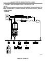
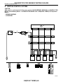
C: CHECK ENGINE MALFUNCTION INDICATOR LAMP (MIL) DOES NOT COME
ON.
• DIAGNOSIS:
• The CHECK ENGINE malfunction indicator lamp (MIL) circuit is open or shorted.
• TROUBLE SYMPTOM:
• When ignition switch is turned ON (engine OFF), MIL does not come on.
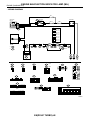
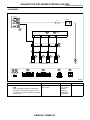
• WIRING DIAGRAM:
BATTERY
No.5
B72
IGNITION
RELAY
IGNITION
SWITCH
SBF-4
B157
23
LHD
SBF-1
1
RHD
B36
B36
i1
i1
4
*
*
*
*
4
4
3
2
1
LHD
*1
LHD : 9
RHD : 38
*2
LHD : 13
RHD : 36
*3
LHD : 11
RHD : 34
*4
LHD : 10
RHD : 37
*5
LHD : 16
RHD : 13
RHD
A7
*5
C6
i2
B37
15
COMBINATION
METER
A:
i10
C:
i12
B137
B72
C:
1 2
3 4
E
ECM
i12
i10
1 2 3
4 5 6
7 8 9 10 11 12 13 14
1 2 3 4 5 6 7 8 9 10
B157
1
2
3
4
5
6
7
8
B137
1 2
3 4 5 6 7 8 9
10 11 12 13 14 15 16 17 18 19 20 21
22 23 24 25 26
27 28
29 30 31
B36
7 8 9 10 11
1 2 3 4 5 6
12 13 14 15 16 17 18 19 20 21 22 23 24
9 14 15 16 19 24 25 26 29 34 35 36
10
17
20
27
30
37
11 12 13 18 21 22 23 28 31 32 33 38
E
i2
1 2 3 4 5
6 7 8 9 10 11
12 13 14 15 16 17 18 19 20 21 22 23 24
(LHD)
i1
1 2 3
4 5 6
7 8 9 10 11 12 13 14
1 2 3 4
5 6 7 8 9
10 11 12 13 14 15 16 17 18 19 20 21
22 23 24 25 26 27 28 29 30 31 32
(RHD)
EN0956
1
Step
CHECK OUTPUT SIGNAL FROM ECM.
1)Turn ignition switch to ON.
2)Measure voltage between ECM connector
and chassis ground.
Connector & terminal
(B137) No. 15 (+) — Chassis ground (−):
Check
Is the voltage less than 1 V?
EN(DOHC TURBO)-44
Yes
Go to step 4.
No
Go to step 2.
ENGINE MALFUNCTION INDICATOR LAMP (MIL)
ENGINE (DIAGNOSTICS)
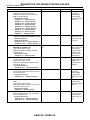
2
Step
CHECK POOR CONTACT.
3
CHECK ECM CONNECTOR.
4
Is resistance less than 1 Ω?
CHECK HARNESS BETWEEN COMBINATION METER AND ECM CONNECTOR.
1)Turn ignition switch to OFF.
2)Remove combination meter. <Ref. to IDI-19,
Combination Meter Assembly.>
3)Disconnect connector from ECM and combination meter.
4)Measure resistance of harness between
ECM and combination meter connector.
Connector & terminal
(B137) No. 15 — (i12) No. 6:
5
6
7
Check
Does the MIL come on when
shaking or pulling ECM connector and harness?
Is ECM connector correctly
connected?
Is there poor contact in combiCHECK POOR CONTACT.
Check poor contact in combination meter con- nation meter connector?
nector.
Is voltage more than 10 V?
CHECK HARNESS BETWEEN COMBINATION METER AND IGNITION SWITCH CONNECTOR.
1)Turn ignition switch to ON.
2)Measure voltage between combination
meter connector and chassis ground.
Connector & terminal
(i10) No. 7 (+) — Chassis ground (−):
CHECK LAMP BULB.
Remove engine malfunction indicator lamp
bulb.
Is lamp bulb condition OK?
EN(DOHC TURBO)-45
Yes
Repair poor contact in ECM connector.
Replace ECM.
<Ref. to FU(DOHC
TURBO)-45,
Engine Control
Module.>
Go to step 5.
No
Go to step 3.
Repair connection
of ECM connector.
Repair harness
and connector.
NOTE:
In this case, repair
the following:
• Open circuit in
harness between
ECM and combination meter connector
• Poor contact in
coupling connector
Go to step 6.
Repair poor contact in combination
meter connector.
Go to step 7.
Check the following and repair if
necessary.
NOTE:
• Broken down
ignition relay.
• Blown out fuse
(No. 5).
• If replaced fuse
(No. 5) blows easily, check the harness for short
circuit of harness
between fuse (No.
5) and ignition
relay connector.
• Open or short
circuit in harness
between fuse (No.
5) and battery terminal
• Open circuit in
harness between
fuse (No. 5) and
ignition relay connector
• Poor contact in
ignition relay connector
• Poor contact in
ignition switch connector
Repair combina- Replace lamp
tion meter connec- bulb.
tor.
ENGINE MALFUNCTION INDICATOR LAMP (MIL)
ENGINE (DIAGNOSTICS)
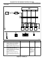
D: CHECK ENGINE MALFUNCTION INDICATOR LAMP (MIL) DOES NOT GO
OFF.
• DIAGNOSIS:
• The CHECK ENGINE malfunction indicator lamp (MIL) circuit is shorted.
• TROUBLE SYMPTOM:
• Although MIL comes on when engine runs, trouble code is not shown on Subaru select monitor or OBDII general scan tool display.
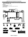
• WIRING DIAGRAM:
BATTERY
No.5
B72
IGNITION
RELAY
IGNITION
SWITCH
SBF-4
B157
23
LHD
SBF-1
1
RHD
B36
B36
i1
i1
4
*
*
*
*
4
4
3
2
1
LHD
*1
LHD : 9
RHD : 38
*2
LHD : 13
RHD : 36
*3
LHD : 11
RHD : 34
*4
LHD : 10
RHD : 37
*5
LHD : 16
RHD : 13
RHD
A7
*5
C6
i2
B37
15
COMBINATION
METER
A:
i10
C:
i12
B137
B72
C:
1 2
3 4
E
ECM
i12
i10
1 2 3
4 5 6
7 8 9 10 11 12 13 14
1 2 3 4 5 6 7 8 9 10
B157
1
2
3
4
5
6
7
8
B36
7 8 9 10 11
1 2 3 4 5 6
12 13 14 15 16 17 18 19 20 21 22 23 24
9 14 15 16 19 24 25 26 29 34 35 36
10
17
20
27
30
37
11 12 13 18 21 22 23 28 31 32 33 38
E
B137
1 2
3 4 5 6 7 8 9
10 11 12 13 14 15 16 17 18 19 20 21
22 23 24 25 26
27 28
29 30 31
i2
1 2 3 4 5
6 7 8 9 10 11
12 13 14 15 16 17 18 19 20 21 22 23 24
(LHD)
i1
1 2 3
4 5 6
7 8 9 10 11 12 13 14
1 2 3 4
5 6 7 8 9
10 11 12 13 14 15 16 17 18 19 20 21
22 23 24 25 26 27 28 29 30 31 32
(RHD)
EN0956
1
Step
CHECK HARNESS BETWEEN COMBINATION METER AND ECM CONNECTOR.
1)Turn ignition switch to OFF.
2)Disconnect connector from ECM.
3)Turn ignition switch to ON.
Check
Does the MIL come on?
EN(DOHC TURBO)-46
Yes
Repair short circuit
in harness
between combination meter and
ECM connector.
No
Replace ECM.
<Ref. to FU(DOHC
TURBO)-45,
Engine Control
Module.>
ENGINE MALFUNCTION INDICATOR LAMP (MIL)
ENGINE (DIAGNOSTICS)
E: CHECK ENGINE MALFUNCTION INDICATOR LAMP (MIL) DOES NOT BLINK
AT A CYCLE OF 3 HZ.
• DIAGNOSIS:
• The CHECK ENGINE malfunction indicator lamp (MIL) circuit is open or shorted.
• Test mode connector circuit is in open.
• TROUBLE SYMPTOM:
• When inspection mode, MIL does not blink at a cycle of 3 Hz.
EN(DOHC TURBO)-47
ENGINE MALFUNCTION INDICATOR LAMP (MIL)
ENGINE (DIAGNOSTICS)
• WIRING DIAGRAM:
No.5
IGNITION
B72 SWITCH
IGNITION
RELAY
BATTERY
SBF-4
1
B157
A7
C6
i12
B37
B126
1
1
B75
B76
LHD
RHD
C:
B125
LHD : 9
RHD : 38
*2
LHD : 13
RHD : 36
*3
LHD : 11
RHD : 34
*4
LHD : 10
RHD : 37
*5
LHD : 16
RHD : 13
D2
B209
16
LHD
F76
F60
:LHD
B22
:RHD
E3
A5
i10
1
i2
B15
A:
*5
COMBINATION
METER
*1
RHD
4
* 43
*2
*1
*
SBF-1
A : B134
ECM
E
B : B137
B75
B76
B125
B126
1
2
1
2
B72
1 2
3 4
1
5
9
13
F60
: LHD
B22
: RHD
2
6
10
14
3
7
11
15
C:
B209
i12
A1 K2 A3
B1 L2
C1 M2 C3
D1 N2
E1
1 2 3
4 5 6
7 8 9 10 11 12 13 14
4
8
12
16
F1
G1Q2
H1 R2
I1 S2
J1 T2
B137
i10
1 2 3 4 5 6 7 8 9 10
B134
1 2
3 4 5 6 7 8 9
10 11 12 13 14 15 16 17 18 19 20 21
22 23 24 25 26
27 28
29 30 31
1 2 3 4 5
6 7
8 9 10 11 12 13 14 15
16 17
18 19 20 21 22
E
E
K4 A5
L4 B5
M4 C5
N4 D5
E5
F5
Q4 G5
H3 R4 H5
S4 I5
J3 T4 J5
i2
1 2 3 4 5
6 7 8 9 10 11
12 13 14 15 16 17 18 19 20 21 22 23 24
(LHD)
B36
1 2 3 4 5 6
7 8 9 10 11
12 13 14 15 16 17 18 19 20 21 22 23 24
1 2 3 4
5 6 7 8 9
10 11 12 13 14 15 16 17 18 19 20 21
22 23 24 25 26 27 28 29 30 31 32
B157
1
2
3
4
5
6
7
8
9 14 15 16 19 24 25 26 29 34 35 36
10
17
20
27
30
37
11 12 13 18 21 22 23 28 31 32 33 38
(RHD)
EN0957
EN(DOHC TURBO)-48
ENGINE MALFUNCTION INDICATOR LAMP (MIL)
ENGINE (DIAGNOSTICS)
1
Step
Check
CHECK STATUS OF CHECK ENGINE MAL- Does the MIL come on?
FUNCTION INDICATOR LAMP (MIL).
1)Turn ignition switch to OFF.
2)Disconnect test mode connector.
3)Turn ignition switch to ON. (engine OFF)
Does the MIL come on?
2
CHECK HARNESS BETWEEN COMBINATION METER AND ECM CONNECTOR.
1)Turn ignition switch to OFF.
2)Disconnect connector from ECM.
3)Turn ignition switch to ON.
3
CHECK HARNESS BETWEEN TEST MODE Is resistance less than 1 Ω?
CONNECTOR AND CHASSIS GROUND.
1)Turn ignition switch to OFF.
2)Disconnect connector from ECM.
3)Measure resistance of harness between test
mode connector and chassis ground.
Connector & terminal
(B76) No. 1 — Chassis ground:
4
CHECK POOR CONTACT.
Check poor contact in ECM connector.
Is there poor contact in ECM
connector?
5
CHECK HARNESS BETWEEN ECM AND
TEST MODE CONNECTOR.
1)Connect test mode connector.
2)Measure resistance of harness between
ECM and chassis ground.
Connector & terminal
(B134) No. 5 — Chassis ground:
CHECK POOR CONTACT.
Check poor contact in ECM connector.
Is resistance less than 1 Ω?
6
Is there poor contact in ECM
connector?
EN(DOHC TURBO)-49
Yes
Go to step 2.
No
Repair the MIL circuit. <Ref. to
EN(DOHC
TURBO)-44,
CHECK ENGINE
MALFUNCTION
INDICATOR
LAMP (MIL)
DOES NOT
COME ON.,
Engine Malfunction Indicator
Lamp (MIL).>
Go to step 3.
Repair ground
short circuit in harness between
combination meter
and ECM connector.
Go to step 4.
Repair harness
and connector.
Repair poor contact in ECM connector.
Go to step 6.
Repair poor contact in ECM connector.
NOTE:
In this case, repair
the following:
• Open circuit in
harness between
test mode connector and chassis
ground
Go to step 5.
Repair open circuit
in harness
between ECM and
test mode connector.
Replace ECM.
<Ref. to FU(DOHC
TURBO)-45,
Engine Control
Module.>
ENGINE MALFUNCTION INDICATOR LAMP (MIL)
ENGINE (DIAGNOSTICS)
F: CHECK ENGINE MALFUNCTION INDICATOR LAMP (MIL) REMAINS BLINKING AT A CYCLE OF 3 HZ.
• DIAGNOSIS:
• Test mode connector circuit is shorted.
• TROUBLE SYMPTOM:
• MIL blinks at a cycle of 3 Hz when ignition switch is turned to ON.
• WIRING DIAGRAM:
No.5
IGNITION
B72 SWITCH
IGNITION
RELAY
BATTERY
SBF-4
1
B157
A7
C6
B126
1
1
B75
B76
LHD
RHD
B125
B37
*2
LHD : 13
RHD : 36
*3
LHD : 11
RHD : 34
*4
LHD : 10
RHD : 37
*5
LHD : 16
RHD : 13
D2
B209
16
LHD
F76
i12
B15
C:
i10
1
i2
LHD : 9
RHD : 38
F60
:LHD
B22
:RHD
E3
A5
A:
*5
COMBINATION
METER
*1
RHD
4
* 43
*2
*1
*
SBF-1
A : B134
ECM
E
B : B137
B75
B76
B72
F60
: LHD
B125
B126
1 2
3 4
B22
: RHD
1
2
1
2
1
5
9
13
2
6
10
14
3
7
11
15
C:
B209
i12
A1 K2 A3
B1 L2
C1 M2 C3
D1 N2
E1
1 2 3
4 5 6
7 8 9 10 11 12 13 14
4
8
12
16
F1
G1Q2
H1 R2
I1 S2
J1 T2
B137
i10
1 2 3 4 5 6 7 8 9 10
B134
1 2
3 4 5 6 7 8 9
10 11 12 13 14 15 16 17 18 19 20 21
22 23 24 25 26
27 28
29 30 31
1 2 3 4 5
6 7
8 9 10 11 12 13 14 15
16 17
18 19 20 21 22
E
E
K4 A5
L4 B5
M4 C5
N4 D5
E5
F5
Q4 G5
H5
H3 R4
S4 I5
J3 T4 J5
i2
1 2 3 4 5
6 7 8 9 10 11
12 13 14 15 16 17 18 19 20 21 22 23 24
(LHD)
B36
1 2 3 4 5 6
7 8 9 10 11
12 13 14 15 16 17 18 19 20 21 22 23 24
1 2 3 4
5 6 7 8 9
10 11 12 13 14 15 16 17 18 19 20 21
22 23 24 25 26 27 28 29 30 31 32
B157
1
2
3
4
5
6
7
8
9 14 15 16 19 24 25 26 29 34 35 36
10
17
20
27
30
37
11 12 13 18 21 22 23 28 31 32 33 38
(RHD)
EN0957
EN(DOHC TURBO)-50
ENGINE MALFUNCTION INDICATOR LAMP (MIL)
ENGINE (DIAGNOSTICS)
1
2
Step
CHECK TEST MODE CONNECTOR.
1)Disconnect test mode connector.
2)Turn ignition switch to ON.
Check
Does MIL flash on and off?
CHECK HARNESS BETWEEN ECM CONNECTOR AND ENGINE GROUNDING TERMINAL.
1)Turn ignition switch to OFF.
2)Disconnect connector from ECM.
3)Measure resistance of harness between
ECM connector and chassis ground.
Connector & terminal
(B134) No. 5 — Chassis ground:
Is resistance less than 5 Ω?
EN(DOHC TURBO)-51
Yes
Go to step 2.
No
System is in good
order.
NOTE:
MIL blinks at a cycle of 3 Hz when
test mode connector is connected.
Repair short circuit Replace ECM.
in harness
<Ref. to FU(DOHC
between ECM and TURBO)-45,
test mode connec- Engine Control
tor.
Module.>
DIAGNOSTICS FOR ENGINE STARTING FAILURE
ENGINE (DIAGNOSTICS)
15.Diagnostics for Engine Starting Failure
A: PROCEDURE
1. Inspection of starter motor circuit. <Ref. to EN(DOHC TURBO)-54, STARTER MOTOR CIRCUIT, Diagnostics for Engine
Starting Failure.>
↓
2. Inspection of ECM power supply and ground line. <Ref. to EN(DOHC TURBO)-56, CONTROL MODULE POWER SUPPLY
AND GROUND LINE, Diagnostics for Engine Starting Failure.>
↓
3. Inspection of ignition control system. <Ref. to EN(DOHC TURBO)-60, IGNITION CONTROL SYSTEM, Diagnostics for
Engine Starting Failure.>
↓
4. Inspection of fuel pump circuit. <Ref. to EN(DOHC TURBO)-64, FUEL PUMP CIRCUIT, Diagnostics for Engine Starting Failure.>
↓
5. Inspection of fuel injector circuit. <Ref. to EN(DOHC TURBO)-66, FUEL INJECTOR CIRCUIT, Diagnostics for Engine Starting Failure.>
EN(DOHC TURBO)-52
DIAGNOSTICS FOR ENGINE STARTING FAILURE
ENGINE (DIAGNOSTICS)
EN(DOHC TURBO)-53
DIAGNOSTICS FOR ENGINE STARTING FAILURE
ENGINE (DIAGNOSTICS)
B: STARTER MOTOR CIRCUIT
CAUTION:
After repair or replacement of faulty parts, conduct CLEAR MEMORY MODE<Ref. to EN(DOHC TURBO)-38, Clear Memory Mode.> and INSPECTION MODE <Ref. to EN(DOHC TURBO)-35, Inspection
Mode.> .
• WIRING DIAGRAM:
BATTERY
SBF-1
1
SBF-4
IGNITION
SWITCH
3
B72
B134 ECM
16
B14
STARTER
MOTOR
E
E
B72
1 2
3 4
B134
1 2 3 4 5
6 7
8 9 10 11 12 13 14 15
16 17
18 19 20 21 22
EN0958
1
Step
Check
CHECK OPERATION OF STARTER MOTOR. Does starter motor operate
when the switch starts?
EN(DOHC TURBO)-54
Yes
Go to step 2.
No
Go to step 3.
DIAGNOSTICS FOR ENGINE STARTING FAILURE
ENGINE (DIAGNOSTICS)
2
3
4
5
6
7
8
9
Step
Check
Is the trouble code stored in
CHECK DTC.
<Ref. to EN(DOHC TURBO)-34, OPERATION, memory? <Ref. to EN(DOHC
Read Diagnostic Trouble Code.>
TURBO)-69, LIST, List of Diagnostic Trouble Code (DTC).>
Yes
No
Record DTC.
Go to step 3.
Repair the trouble
case. <Ref. to
EN(DOHC
TURBO)-74, Diagnostic Procedure
with Diagnostic
Trouble Code
(DTC).>
Go to step 5.
CHECK INPUT SIGNAL FOR STARTER MO- Is the voltage more than 10 V? Go to step 4.
TOR.
1)Turn ignition switch to OFF.
2)Disconnect connector from starter motor.
3)Turn ignition switch to ST.
4)Measure power supply voltage between
starter motor connector terminal and engine
ground.
Connector & terminal
(B14) No. 1 (+) — Engine ground (−):
Is resistance less than 5 Ω?
Check starter
Repair open circuit
CHECK GROUND CIRCUIT OF STARTER
motor. <Ref. to
of ground cable.
MOTOR.
1)Turn ignition switch to OFF.
SC-5, Starter.>
2)Disconnect terminal from starter motor.
3)Measure resistance of ground cable between
ground cable terminal and engine ground.
Is resistance less than 1 Ω?
Repair ground
Go to step 6.
CHECK HARNESS BETWEEN ECM AND
short circuit.
STARTER MOTOR CIRCUIT.
1)Turn ignition switch to OFF.
2)Measure resistance between starter motor
and ECM.
Connector & terminal
(B14) No. 1 — Engine ground:
Is resistance less than 1 Ω?
Go to step 7.
Repair ground
CHECK HARNESS BETWEEN ECM AND
short circuit.
STARTER MOTOR CIRCUIT.
1)Turn ignition switch to START.
2)Measure resistance of fuse.
Connector & terminal
(B14) No. 1 — Engine ground:
Is the voltage more than 10 V? Go to step 8.
Repair open circuit
CHECK HARNESS BETWEEN BATTERY
in harness
AND IGNITION SWITCH CONNECTOR.
between ignition
1)Ignition switch to OFF.
2)Disconnect connector from ignition switch.
switch and battery.
3)Measure power supply voltage between ignition switch connector and chassis ground.
Connector & terminal
(B72) No. 1 (+) — Chassis ground (−):
Is the voltage more than 10 V? Repair open circuit Go to step 9.
CHECK HARNESS BETWEEN BATTERY
between ignition
AND IGNITION SWITCH CONNECTOR.
1)Connect connector to ignition switch.
switch and starter
2)Turn ignition switch to START.
motor circuit.
3)Measure voltage between ignition switch and
chassis ground.
Connector & terminal
(B72) No. 3 (+) — Chassis ground (−):
Is there poor contact in ignition Repair poor con- Replace ignition
CHECK POOR CONTACT.
Check poor contact in ignition switch connec- switch connector?
tact in ignition
switch.
tor.
switch connector.
EN(DOHC TURBO)-55
DIAGNOSTICS FOR ENGINE STARTING FAILURE
ENGINE (DIAGNOSTICS)
C: CONTROL MODULE POWER SUPPLY AND GROUND LINE
CAUTION:
After repair or replacement of faulty parts, conduct CLEAR MEMORY MODE<Ref. to EN(DOHC TURBO)-38, Clear Memory Mode.> and INSPECTION MODE. <Ref. to EN(DOHC TURBO)-35, Inspection
Mode.>
• WIRING DIAGRAM:
• LHD MODEL
MAIN RELAY
TO FRONT OXYGEN(A/F) SENSOIR
4
6
2
SBF-5
8
5
3
B61
2
1
B72
F44
IGNITION
SWITCH
BATTERY
No.11
SBF-4
B47
1
A2
D2
D3
D10
A14
4
SBF-1
A : B134
C : B136
ECM
D : B137
E:
D8
D9
A22
C17
C8
C18
A7
A15
E1
B84
C3
F1
D2
J3
A3
B209
3
15
13
14
16
F76
F60
E3
E
B72
B47
1
3
5
1 2
3 4
F1
G1Q2
H1 R2
I1 S2
J1 T2
A : B134
F60
2
4
6
1
5
9
13
2
6
10
14
3
7
11
15
4
8
12
16
D : B137
B209
A1 K2 A3
B1 L2
C1 M2 C3
D1 N2
E1
E
E
K4 A5
L4 B5
M4 C5
N4 D5
E5
1 2
3 4 5 6 7 8 9
10 11 12 13 14 15 16 17 18 19 20 21
22 23 24 25 26
27 28
29 30 31
1 2 3 4 5
6 7
8 9 10 11 12 13 14 15
16 17
18 19 20 21 22
E:
C : B136
1 2
3 4 5 6 7
8 9 10 11 12 13 14 15 16
22 23 24
17 18 19 20 21
B84
1 2 3 4 5 6
7 8 9 10 11 12
13 14 15
16 17
F5
Q4 G5
H5
R4
H3
S4 I5
J3 T4 J5
EN0959
EN(DOHC TURBO)-56
DIAGNOSTICS FOR ENGINE STARTING FAILURE
ENGINE (DIAGNOSTICS)
• RHD MODEL
MAIN RELAY
DATA LINK CONNECTOR
4
6
SBF-5
5
3
2
1
B72
IGNITION
SWITCH
BATTERY
No.11
B47
SBF-4
1
A2
D2
D3
D10
A14
4
SBF-1
A:
B134
C : B136
ECM
D : B137
B84
13
14
16
15
3
D8
D9
A22
C17
C8
C18
A7
A15
E1
E:
B22
E3
E
B72
1 2
3 4
E
E
B47
1
3
5
2
4
6
A : B134
B22
1
5
9
13
2
6
10
14
3
7
11
15
4
8
12
16
1 2 3 4 5
6 7
8 9 10 11 12 13 14 15
16 17
18 19 20 21 22
E:
C : B136
D : B137
1 2
3 4 5 6 7
8 9 10 11 12 13 14 15 16
22 23 24
17 18 19 20 21
1 2
3 4 5 6 7 8 9
10 11 12 13 14 15 16 17 18 19 20 21
22 23 24 25 26
27 28
29 30 31
B84
1 2 3 4 5 6
7 8 9 10 11 12
13 14 15
16 17
EN0960
1
Step
Check
Is the resistance less than 10
CHECK MAIN RELAY.
1)Turn the ignition switch to OFF.
Ω?
2)Remove main relay.
3)Connect battery to main relay terminals No.
1 and No. 2.
4)Measure resistance between main relay terminals.
Terminals
No. 3 — No. 5:
No. 4 — No. 6:
EN(DOHC TURBO)-57
Yes
Go to step 2.
No
Replace main
relay.
DIAGNOSTICS FOR ENGINE STARTING FAILURE
ENGINE (DIAGNOSTICS)
2
3
4
5
6
7
8
Step
CHECK GROUND CIRCUIT OF ECM.
1)Disconnect connector from ECM.
2)Measure resistance of harness between
ECM and chassis ground.
Connector & terminal
(B134) No. 7 — Chassis ground:
(B134) No. 15 — Chassis ground:
(B134) No. 22 — Chassis ground:
(B136) No. 8 — Chassis ground:
(B136) No. 17 — Chassis ground:
(B136) No. 18 — Chassis ground:
(B137) No. 8 — Chassis ground:
(B137) No. 9 — Chassis ground:
(B84) No. 1 — Chassis ground:
CHECK INPUT VOLTAGE OF ECM.
Measure voltage between ECM connector
and chassis ground.
Connector & terminal
(B137) No. 10 (+) — Chassis ground (–):
(B134) No. 14 (+) — Chassis ground (–):
CHECK HARNESS BETWEEN ECM AND
MAIN RELAY CONNECTOR.
1)Turn ignition switch to OFF.
2)Measure resistance between ECM and
chassis ground.
Connector & terminal
(B134) No. 2 — Chassis ground:
CHECK OUTPUT VOLTAGE FROM ECM.
1)Connect connector to ECM.
2)Turn ignition switch to ON.
3)Measure voltage between ECM connector
and chassis ground.
Connector & terminal
(B134) No. 2 (+) — Chassis ground (–):
CHECK INPUT VOLTAGE OF MAIN RELAY.
Check voltage between main relay connector
and chassis ground.
Connector & terminal
(B47) No. 2 (+) — Chassis ground (–):
Check
Is the resistance less than 5
Ω?
Yes
Go to step 3.
No
Repair open circuit
in harness
between ECM
connector and
engine grounding
terminal.
Is the voltage more than 10 V? Go to step 4.
Repair open or
ground short circuit of power supply circuit.
Is the resistance more than 1
MΩ?
Repair ground
short circuit in harness between
ECM connector
and main relay
connector, then
replace ECM.
Replace ECM.
<Ref. to FU(DOHC
TURBO)-45,
Engine Control
Module.>
Go to step 5.
Is the voltage more than 10 V? Go to step 6.
Is the voltage more than 10 V? Go to step 7.
Is the resistance less than 5
Go to step 8.
CHECK GROUND CIRCUIT OF MAIN REΩ?
LAY.
1)Turn ignition switch to OFF.
2)Measure resistance between main relay connector and chassis ground.
Connector & terminal
(B47) No. 1 — Chassis ground:
CHECK INPUT VOLTAGE OF MAIN RELAY. Is the voltage more than 10 V? Go to step 9.
Measure voltage between main relay connector and chassis ground.
Connector & terminal
(B47) No. 5 (+) — Chassis ground (−):
(B47) No. 6 (+) — Chassis ground (−):
EN(DOHC TURBO)-58
Repair open circuit
in harness
between ECM
connector and
main relay connector.
Repair open circuit
between main
relay and chassis
ground.
Repair open or
ground short circuit in harness of
power supply circuit.
DIAGNOSTICS FOR ENGINE STARTING FAILURE
ENGINE (DIAGNOSTICS)
9
Step
CHECK INPUT VOLTAGE OF ECM.
1)Connect main relay connector.
2)Turn ignition switch to ON.
3)Measure voltage between ECM connector
and chassis ground.
Connector & terminal
(B137) No. 2 (+) — Chassis ground (–):
(B137) No. 3 (+) — Chassis ground (–):
Check
Yes
Is the voltage more than 10 V? Check ignition
control system.
<Ref. to EN(DOHC
TURBO)-60, IGNITION CONTROL
SYSTEM, Diagnostics for Engine
Starting Failure.>
EN(DOHC TURBO)-59
No
Repair open or
ground short circuit in harness
between ECM
connector and
main relay connector.
DIAGNOSTICS FOR ENGINE STARTING FAILURE
ENGINE (DIAGNOSTICS)
D: IGNITION CONTROL SYSTEM
CAUTION:
After repair or replacement of faulty parts, conduct CLEAR MEMORY MODE<Ref. to EN(DOHC TURBO)-38, Clear Memory Mode.> and INSPECTION MODE <Ref. to EN(DOHC TURBO)-35, Inspection
Mode.> .
• WIRING DIAGRAM:
• LHD MODEL
SBF-1
21
22
ECM
23
24
B136
No.11
SBF-4
4
1
E5
E1
D5
D4
H3
5
B209
4
IGNITION
SWITCH B72
F76
8
7
6
F60
E3
2
1
E34
3
2
1
E33
3
2
1
E32
3
2
1
3
E31
E
E
IGNITION COIL
No.1
E31
E32
E33
E34
F60
1
5
9
13
2
6
10
14
3
7
11
15
B72
4
8
12
16
1 2
3 4
IGNITION COIL
No.2
IGNITION COIL
No.3
IGNITION COIL
No.4
B209
B136
1 2
3 4 5 6 7
8 9 10 11 12 13 14 15 16
22 23 24
17 18 19 20 21
1
2
3
A1 K2 A3
B1 L2
C1 M2 C3
D1 N2
E1
F1
G1Q2
H1 R2
I1 S2
J1 T2
K4 A5
L4 B5
M4 C5
N4 D5
E5
F5
Q4 G5
H3 R4 H5
S4 I5
J3 T4 J5
EN0961
EN(DOHC TURBO)-60
DIAGNOSTICS FOR ENGINE STARTING FAILURE
ENGINE (DIAGNOSTICS)
• RHD MODEL
SBF-1
21
22
ECM
23
24
B136
No.11
SBF-4
4
1
8
7
6
5
4
B22
E3
2
1
3
E34
2
1
E33
3
2
1
E32
3
2
1
3
E31
E
E
IGNITION COIL
No.1
E31
E32
E33
E34
B22
1
5
9
13
2
6
10
14
3
7
11
15
IGNITION COIL
No.2
IGNITION COIL
No.3
B136
4
8
12
16
IGNITION COIL
No.4
B72
1 2
3 4 5 6 7
8 9 10 11 12 13 14 15 16
22 23 24
17 18 19 20 21
1 2
3 4
1
2
3
EN0962
1
2
Step
Check
Is spark plug’s status OK?
CHECK SPARK PLUG CONDITION.
1)Remove spark plug. <Ref. to IG(DOHC
TURBO)-5, INSTALLATION, Spark Plug.>
2)Check spark plug condition. <Ref. to
IG(DOHC TURBO)-6, INSPECTION, Spark
Plug.>
CHECK IGNITION SYSTEM FOR SPARKS. Does spark occur at each cyl1)Connect spark plug to ignition coil.
inder?
2)Release fuel pressure. <Ref. to FU(DOHC
TURBO)-49, RELEASING OF FUEL PRESSURE, OPERATION, Fuel.>
3)Contact spark plug's thread portion on
engine.
4)While opening throttle valve fully, crank
engine to check that spark occurs at each cylinder.
EN(DOHC TURBO)-61
Yes
Go to step 2.
No
Replace spark
plug
Check fuel pump Go to step 3.
system. <Ref. to
EN(DOHC
TURBO)-64, FUEL
PUMP CIRCUIT,
Diagnostics for
Engine Starting
Failure.>
DIAGNOSTICS FOR ENGINE STARTING FAILURE
ENGINE (DIAGNOSTICS)
3
4
5
6
7
Step
Check
Yes
CHECK POWER SUPPLY CIRCUIT FOR IG- Is the voltage more than 10 V? Go to step 4.
NITION COIL & IGNITOR ASSEMBLY.
1)Turn ignition switch to OFF.
2)Disconnect connector from ignition coil &
ignitor assembly.
3)Turn ignition switch to ON.
4)Measure power supply voltage between ignition coil & ignitor assembly connector and
engine ground.
Connector & terminal
(E31) No. 3 (+) — Engine ground (−):
(E32) No. 3 (+) — Engine ground (−):
(E33) No. 3 (+) — Engine ground (−):
(E34) No. 3 (+) — Engine ground (−):
CHECK HARNESS OF IGNITION COIL & IG- Is the resistance between less Go to step 5.
than 5 Ω?
NITOR ASSEMBLY GROUND CIRCUIT.
1)Turn ignition switch to OFF.
2)Measure resistance between ignition coil &
ignitor assembly connector and engine ground.
Connector & terminal
(E31) No. 2 — Engine ground:
(E32) No. 2 — Engine ground:
(E33) No. 2 — Engine ground:
(E34) No. 2 — Engine ground:
CHECK HARNESS BETWEEN ECM AND IGNITION COIL & IGNITOR ASSEMBLY CONNECTOR.
1)Turn ignition switch to OFF.
2)Disconnect connector from ECM.
3)Disconnect connector from ignition coil &
ignitor assembly.
4)Measure resistance of harness between
ECM and ignition coil & ignitor assembly connector.
Connector & terminal
(B136) No. 21 — (E34) No. 1:
(B136) No. 22 — (E33) No. 1:
(B136) No. 23 — (E32) No. 1:
(B136) No. 24 — (E31) No. 1:
CHECK HARNESS BETWEEN ECM AND IGNITION COIL & IGNITOR ASSEMBLY CONNECTOR.
Measure resistance of harness between ECM
and engine ground.
Connector & terminal:
(B136) No. 21 — Engine ground:
(B136) No. 22 — Engine ground:
(B136) No. 23 — Engine ground:
(B136) No. 24 — Engine ground:
CHECK POOR CONTACT.
Check poor contact in ECM connector.
Is the resistance less than 1
Ω?
Go to step 6.
No
Repair harness
and connector.
NOTE:
In this case, repair
the following:
• Open circuit in
harness between
ignition coil & ignitor assembly, and
ignition switch connector
• Poor contact in
coupling connectors
Repair harness
and connector.
NOTE:
In this case, repair
the following:
• Open circuit in
harness between
ignition coil & ignitor assembly connector and engine
grounding terminal
Repair harness
and connector.
NOTE:
In this case, repair
the following:
• Open circuit in
harness between
ECM and ignition
coil & ignitor
assembly connector
• Poor contact in
coupling connector
Is the resistance more than 1
MΩ?
Go to step 7.
Repair ground
short circuit in harness between
ECM and ignition
coil & ignitor
assembly connector.
Is there poor contact in ECM
connector?
Repair poor contact in ECM connector.
Replace ignition
coil and ignitor
assembly.
EN(DOHC TURBO)-62
DIAGNOSTICS FOR ENGINE STARTING FAILURE
ENGINE (DIAGNOSTICS)
EN(DOHC TURBO)-63
DIAGNOSTICS FOR ENGINE STARTING FAILURE
ENGINE (DIAGNOSTICS)
E: FUEL PUMP CIRCUIT
*3
4
B97
2
RHD
RHD
CAUTION:
After repair or replacement of faulty parts, conduct CLEAR MEMORY MODE<Ref. to EN(DOHC TURBO)-38, Clear Memory Mode.> and INSPECTION MODE <Ref. to EN(DOHC TURBO)-35, Inspection
Mode.> .
• WIRING DIAGRAM:
LHD
F44
10
R1
LHD
8
B61
FUEL PUMP
RELAY
B46
BATTERY
SBF-5
FUEL PUMP
CONTROLLER
1
3
R15
5
9
8
*21
*
7
6
R122
R3
B99
A13
C16
2
1
R57
FUEL
PUMP
*1
LHD : 20
RHD : 15
*2
LHD : 19
RHD : 14
*3
LHD : 7
RHD : 5
ECM
M
R58
F44
B97
1 2 3 4
5 6 7 8
A:
B134
C:
B136
E
B46
R122
1 2
3 4
1 2
3 4
5 6 7 8 9 10
B134
B136
1 2 3 4 5
6 7
8 9 10 11 12 13 14 15
16 17
18 19 20 21 22
1 2
3 4 5 6 7
8 9 10 11 12 13 14 15 16
22 23 24
17 18 19 20 21
E
B99
6 7 8 9 10 11
1 2 3 4 5
12 13 14 15 16 17 18 19 20 21 22 23 24
R58
1 2 3
4 5 6
EN0991
EN(DOHC TURBO)-64
DIAGNOSTICS FOR ENGINE STARTING FAILURE
ENGINE (DIAGNOSTICS)
1
Step
CHECK OPERATING SOUND OF FUEL
PUMP.
Make sure that fuel pump is in operation for
two seconds when turning ignition switch to
ON.
Check
Yes
Does fuel pump produce oper- Check fuel injecating sound?
tor circuit. <Ref. to
EN(DOHC
TURBO)-66, FUEL
INJECTOR CIRCUIT, Diagnostics
NOTE:
for Engine StartFuel pump operation can also be executed using Failure.>
ing Subaru Select Monitor (Function mode:
FD01).
For the procedure, refer to “Compulsory Valve
Operation Check Mode”. <Ref. to EN(DOHC
TURBO)-39, Compulsory Valve Operation
Check Mode.>
EN(DOHC TURBO)-65
No
Record DTC.
Repair the trouble
case. <Ref. to
EN(DOHC
TURBO)-74, Diagnostic Procedure
with Diagnostic
Trouble Code
(DTC).>
DIAGNOSTICS FOR ENGINE STARTING FAILURE
ENGINE (DIAGNOSTICS)
F: FUEL INJECTOR CIRCUIT
CAUTION:
• Check or repair only faulty parts.
• After repair or replacement of faulty parts, conduct CLEAR MEMORY MODE <Ref. to EN(DOHC
TURBO)-38, Clear Memory Mode.> and INSPECTION MODE. <Ref. to EN(DOHC TURBO)-35, Inspection Mode.>
• WIRING DIAGRAM:
• LHD MODEL
MAIN RELAY
6
4
B61
BATTERY
F44
SBF-5
5
3
8
2
1
D:
B136
C5
C6
D1
C:
B137
ECM
C4
B47
I5
I4
J4
F44
J5
1
B61
B209
11
10
1
9
12
F76
F60
E3
2
1
E17
2
1
E6
2
1
E16
2
1
E5
#1
#2
#3
#4
E
FUEL INJECTORS
E5
E6
E16
E17
1 2
F44
1 2 3 4
5 6 7 8
B136
1 2
3 4 5 6 7
8 9 10 11 12 13 14 15 16
22 23 24
17 18 19 20 21
B137
1 2
3 4 5 6 7 8 9
10 11 12 13 14 15 16 17 18 19 20 21
22 23 24 25 26
27 28
29 30 31
1
5
9
13
2
6
10
14
3
7
11
15
B209
4
8
12
16
A1 K2 A3
B1 L2
C1 M2 C3
D1 N2
E1
F1
G1Q2
H1 R2
I1 S2
J1 T2
B47
1
3
5
F60
2
4
6
K4 A5
L4 B5
M4 C5
N4 D5
E5
F5
Q4 G5
H3 R4 H5
S4 I5
J3 T4 J5
EN0964
EN(DOHC TURBO)-66
DIAGNOSTICS FOR ENGINE STARTING FAILURE
ENGINE (DIAGNOSTICS)
• RHD MODEL
MAIN RELAY
6
4
BATTERY
SBF-5
5
3
2
1
B47
B137
C4
ECM
B22
12
11
10
1
9
D:
B136
C5
C6
D1
C:
E3
2
1
E17
2
1
E6
2
1
E16
2
1
E5
#1
#2
#3
#4
E
FUEL INJECTORS
E5
E6
E16
E17
1 2
B136
1 2
3 4 5 6 7
8 9 10 11 12 13 14 15 16
22 23 24
17 18 19 20 21
B137
1 2
3 4 5 6 7 8 9
10 11 12 13 14 15 16 17 18 19 20 21
22 23 24 25 26
27 28
29 30 31
B47
B22
1
5
9
13
2
6
10
14
3
7
11
15
4
8
12
16
1
3
5
2
4
6
EN0965
1
Step
Check
CHECK OPERATION OF EACH FUEL INJEC- Is the fuel injector emits “operating” sound?
TOR.
While cranking the engine, check that each
fuel injector emits “operating” sound. Use a
sound scope or attach a screwdriver to injector
for this check.
EN(DOHC TURBO)-67
Yes
Check fuel pressure. <Ref. to
ME(DOHC
TURBO)-27,
INSPECTION,
Fuel Pressure.>
No
Go to step 2.
DIAGNOSTICS FOR ENGINE STARTING FAILURE
ENGINE (DIAGNOSTICS)
2
3
4
5
6
Step
CHECK POWER SUPPLY TO EACH FUEL
INJECTOR.
1)Turn ignition switch to OFF.
2)Disconnect connector from #1 cylinder fuel
injector.
3)Turn ignition switch to ON.
4)Measure power supply voltage between the
fuel injector terminal and engine ground.
Connector & terminal
#1 (E5) No. 2 (+) — Engine ground (–):
#2 (E16) No. 2 (+) — Engine ground (−):
#3 (E6) No. 2 (+) — Engine ground (–):
#4 (E17) No. 2 (+) — Engine ground (–):
Check
Yes
Is the voltage more than 10 V? Go to step 3.
CHECK HARNESS BETWEEN ECM AND
FUEL INJECTOR CONNECTOR.
1)Disconnect connector from ECM.
2)Measure resistance of harness between
ECM and fuel injector connector.
Connector & terminal
(B137) No. 1 — (E5) No. 1:
(B136) No. 6 — (E16) No. 1:
(B136) No. 5 — (E6) No. 1:
(B136) No. 4 — (E6) No. 1:
Is the resistance less than 1
Ω?
CHECK HARNESS BETWEEN ECM AND
FUEL INJECTOR CONNECTOR.
Measure resistance of harness between ECM
and fuel injector connector.
Connector & terminal
(B137) No. 1 — Chassis ground:
(B136) No. 6 — Chassis ground:
(B136) No. 5 — Chassis ground:
(B136) No. 4 — Chassis ground:
CHECK EACH FUEL INJECTOR.
1)Turn ignition switch to OFF.
2)Measure resistance between each fuel injector terminals.
Terminals
No. 1 — No. 2:
CHECK POOR CONTACT.
Check poor contact in ECM connector.
Is the resistance less than 1
Ω?
Repair ground
short circuit in harness between
ECM and fuel
injector connector.
Is the resistance between 5
and 20 Ω?
Go to step 6.
Replace faulty fuel
injector.
Is there poor contact in ECM
connector?
Repair poor contact in ECM connector.
Inspection using
“General Diagnostic Table”. <Ref. to
EN(DOHC
TURBO)-301,
INSPECTION,
General Diagnostic Table.>
EN(DOHC TURBO)-68
Go to step 4.
No
Repair harness
and connector.
NOTE:
In this case, repair
the following:
• Open circuit in
harness between
main relay and fuel
injector connector
• Poor contact in
main relay connector
• Poor contact in
coupling connector
• Poor contact in
fuel injector connector
Repair harness
and connector.
NOTE:
In this case, repair
the following:
• Open circuit in
harness between
ECM and fuel
injector connector
• Poor contact in
coupling connector
Go to step 5.
LIST OF DIAGNOSTIC TROUBLE CODE (DTC)
ENGINE (DIAGNOSTICS)
16.List of Diagnostic Trouble
Code (DTC)
A: LIST
DTC
No.
P0031
P0032
P0037
P0038
P0101
P0102
P0103
P0106
P0107
P0108
P0111
P0112
P0113
P0117
P0118
P0121
P0122
Item
Index
Front oxygen (A/F) sensor heater circuit low input
<Ref. to EN(DOHC TURBO)-74, DTC P0031 — FRONT OXYGEN (A/F)
SENSOR HEATER CIRCUIT LOW INPUT —, Diagnostic Procedure with
Diagnostic Trouble Code (DTC).>
Front oxygen (A/F) sensor heater cir- <Ref. to EN(DOHC TURBO)-78, DTC P0032 — FRONT OXYGEN (A/F)
cuit high input
SENSOR HEATER CIRCUIT HIGH INPUT —, Diagnostic Procedure with
Diagnostic Trouble Code (DTC).>
Rear oxygen sensor heater circuit
<Ref. to EN(DOHC TURBO)-80, DTC P0037 — REAR OXYGEN SENSOR
malfunction
HEATER CIRCUIT MALFUNCTION —, Diagnostic Procedure with Diagnostic Trouble Code (DTC).>
Rear oxygen sensor heater circuit
<Ref. to EN(DOHC TURBO)-84, DTC P0038 — REAR OXYGEN SENSOR
high input
HEATER CIRCUIT HIGH INPUT —, Diagnostic Procedure with Diagnostic
Trouble Code (DTC).>
Mass air flow sensor circuit range/
<Ref. to EN(DOHC TURBO)-86, DTC P0101 — MASS AIR FLOW SENSOR
performance problem (high input)
CIRCUIT RANGE/PERFORMANCE PROBLEM (HIGH INPUT) —, Diagnostic Procedure with Diagnostic Trouble Code (DTC).>
Mass air flow sensor circuit low input <Ref. to EN(DOHC TURBO)-88, DTC P0102 — MASS AIR FLOW SENSOR
CIRCUIT LOW INPUT —, Diagnostic Procedure with Diagnostic Trouble
Code (DTC).>
Mass air flow sensor circuit high
<Ref. to EN(DOHC TURBO)-92, DTC P0103 — MASS AIR FLOW SENSOR
input
CIRCUIT HIGH INPUT —, Diagnostic Procedure with Diagnostic Trouble
Code (DTC).>
Pressure sensor circuit range/perfor- <Ref. to EN(DOHC TURBO)-94, DTC P0106 — PRESSURE SENSOR CIRmance problem (low input)
CUIT RANGE/PERFORMANCE PROBLEM (LOW INPUT) —, Diagnostic
Procedure with Diagnostic Trouble Code (DTC).>
Pressure sensor circuit low input
<Ref. to EN(DOHC TURBO)-98, DTC P0107 — PRESSURE SENSOR CIRCUIT LOW INPUT —, Diagnostic Procedure with Diagnostic Trouble Code
(DTC).>
Pressure sensor circuit high input
<Ref. to EN(DOHC TURBO)-102, DTC P0108 — PRESSURE SENSOR
CIRCUIT HIGH INPUT —, Diagnostic Procedure with Diagnostic Trouble
Code (DTC).>
Intake air temperature sensor circuit <Ref. to EN(DOHC TURBO)-106, DTC P0111 — INTAKE AIR TEMPERArange/performance problem
TURE SENSOR CIRCUIT RANGE/PERFORMANCE PROBLEM —, Diagnostic Procedure with Diagnostic Trouble Code (DTC).>
Intake air temperature sensor circuit <Ref. to EN(DOHC TURBO)-108, DTC P0112 — INTAKE AIR TEMPERAlow input
TURE SENSOR CIRCUIT LOW INPUT —, Diagnostic Procedure with Diagnostic Trouble Code (DTC).>
Intake air temperature sensor circuit <Ref. to EN(DOHC TURBO)-110, DTC P0113 — INTAKE AIR TEMPERAhigh input
TURE SENSOR CIRCUIT HIGH INPUT —, Diagnostic Procedure with Diagnostic Trouble Code (DTC).>
Engine coolant temperature sensor
<Ref. to EN(DOHC TURBO)-114, DTC P0117 — ENGINE COOLANT TEMcircuit low input
PERATURE SENSOR CIRCUIT LOW INPUT —, Diagnostic Procedure with
Diagnostic Trouble Code (DTC).>
Engine coolant temperature sensor
<Ref. to EN(DOHC TURBO)-116, DTC P0118 — ENGINE COOLANT TEMcircuit high input
PERATURE SENSOR CIRCUIT HIGH INPUT —, Diagnostic Procedure with
Diagnostic Trouble Code (DTC).>
Throttle position sensor circuit range/ <Ref. to EN(DOHC TURBO)-120, DTC P0121 — THROTTLE POSITION
performance problem (high input)
SENSOR CIRCUIT RANGE/PERFORMANCE PROBLEM (HIGH INPUT) —
, Diagnostic Procedure with Diagnostic Trouble Code (DTC).>
Throttle position sensor circuit low
<Ref. to EN(DOHC TURBO)-122, DTC P0122 — THROTTLE POSITION
input
SENSOR CIRCUIT LOW INPUT —, Diagnostic Procedure with Diagnostic
Trouble Code (DTC).>
EN(DOHC TURBO)-69
LIST OF DIAGNOSTIC TROUBLE CODE (DTC)
ENGINE (DIAGNOSTICS)
DTC
No.
P0123
Item
Index
Throttle position sensor circuit high
input
P0125
Insufficient coolant temperature for
closed loop fuel control
P0131
Front oxygen (A/F) sensor circuit
range/performance problem (low
input)
Front oxygen (A/F) sensor circuit
range/performance problem (high
input)
Front oxygen (A/F) sensor circuit
slow response
P0132
P0133
P0136
Rear oxygen sensor circuit malfunction
P0139
Rear oxygen sensor circuit slow
response
P0171
Fuel trim malfunction (A/F too lean)
P0172
Fuel trim malfunction (A/F too rich)
P0244
Wastegate control solenoid valve
malfunction (high input)
P0245
Wastegate control solenoid valve circuit low input
P0246
Wastegate control solenoid valve circuit high input
P0301
Cylinder 1 misfire detected
P0302
Cylinder 2 misfire detected
P0303
Cylinder 3 misfire detected
P0304
Cylinder 4 misfire detected
P0327
Knock sensor circuit low input
P0328
Knock sensor circuit high input
P0335
Crankshaft position sensor circuit
malfunction
P0336
Crankshaft position sensor circuit
range/performance problem
<Ref. to EN(DOHC TURBO)-126, DTC P0123 — THROTTLE POSITION
SENSOR CIRCUIT HIGH INPUT —, Diagnostic Procedure with Diagnostic
Trouble Code (DTC).>
<Ref. to EN(DOHC TURBO)-130, DTC P0125 — INSUFFICIENT COOLANT
TEMPERATURE FOR CLOSED LOOP FUEL CONTROL —, Diagnostic
Procedure with Diagnostic Trouble Code (DTC).>
<Ref. to EN(DOHC TURBO)-132, DTC P0131 — FRONT OXYGEN (A/F)
SENSOR CIRCUIT RANGE/PERFORMANCE PROBLEM (LOW INPUT) —,
Diagnostic Procedure with Diagnostic Trouble Code (DTC).>
<Ref. to EN(DOHC TURBO)-134, DTC P0132 — FRONT OXYGEN (A/F)
SENSOR CIRCUIT RANGE/PERFORMANCE PROBLEM (HIGH INPUT) —
, Diagnostic Procedure with Diagnostic Trouble Code (DTC).>
<Ref. to EN(DOHC TURBO)-136, DTC P0133 — FRONT OXYGEN (A/F)
SENSOR CIRCUIT SLOW RESPONSE —, Diagnostic Procedure with Diagnostic Trouble Code (DTC).>
<Ref. to EN(DOHC TURBO)-138, DTC P0136 — REAR OXYGEN SENSOR
CIRCUIT MALFUNCTION —, Diagnostic Procedure with Diagnostic Trouble
Code (DTC).>
<Ref. to EN(DOHC TURBO)-140, DTC P0139 — REAR OXYGEN SENSOR
CIRCUIT SLOW RESPONSE —, Diagnostic Procedure with Diagnostic
Trouble Code (DTC).>
<Ref. to EN(DOHC TURBO)-142, DTC P0171 — FUEL TRIM MALFUNCTION (A/F TOO LEAN) —, Diagnostic Procedure with Diagnostic Trouble
Code (DTC).>
<Ref. to EN(DOHC TURBO)-143, DTC P0172 — FUEL TRIM MALFUNCTION (A/F TOO RICH) —, Diagnostic Procedure with Diagnostic Trouble
Code (DTC).>
<Ref. to EN(DOHC TURBO)-146, DTC P0244 — WASTEGATE CONTROL
SOLENOID VALVE MALFUNCTION (HIGH INPUT) —, Diagnostic Procedure with Diagnostic Trouble Code (DTC).>
<Ref. to EN(DOHC TURBO)-148, DTC P0245 — WASTEGATE CONTROL
SOLENOID VALVE CIRCUIT LOW INPUT —, Diagnostic Procedure with
Diagnostic Trouble Code (DTC).>
<Ref. to EN(DOHC TURBO)-152, DTC P0246 — WASTEGATE CONTROL
SOLENOID VALVE CIRCUIT HIGH INPUT —, Diagnostic Procedure with
Diagnostic Trouble Code (DTC).>
<Ref. to EN(DOHC TURBO)-154, DTC P0301 — CYLINDER 1 MISFIRE
DETECTED —, Diagnostic Procedure with Diagnostic Trouble Code (DTC).>
<Ref. to EN(DOHC TURBO)-154, DTC P0302 — CYLINDER 2 MISFIRE
DETECTED —, Diagnostic Procedure with Diagnostic Trouble Code (DTC).>
<Ref. to EN(DOHC TURBO)-154, DTC P0303 — CYLINDER 3 MISFIRE
DETECTED —, Diagnostic Procedure with Diagnostic Trouble Code (DTC).>
<Ref. to EN(DOHC TURBO)-156, DTC P0304 — CYLINDER 4 MISFIRE
DETECTED —, Diagnostic Procedure with Diagnostic Trouble Code (DTC).>
<Ref. to EN(DOHC TURBO)-164, DTC P0327 — KNOCK SENSOR CIRCUIT LOW INPUT —, Diagnostic Procedure with Diagnostic Trouble Code
(DTC).>
<Ref. to EN(DOHC TURBO)-166, DTC P0328 — KNOCK SENSOR CIRCUIT HIGH INPUT —, Diagnostic Procedure with Diagnostic Trouble Code
(DTC).>
<Ref. to EN(DOHC TURBO)-168, DTC P0335 — CRANKSHAFT POSITION
SENSOR CIRCUIT MALFUNCTION —, Diagnostic Procedure with Diagnostic Trouble Code (DTC).>
<Ref. to EN(DOHC TURBO)-170, DTC P0336 — Crankshaft Position Sensor
Circuit Range/Performance Problem —, Diagnostic Procedure with Diagnostic Trouble Code (DTC).>
EN(DOHC TURBO)-70
LIST OF DIAGNOSTIC TROUBLE CODE (DTC)
ENGINE (DIAGNOSTICS)
DTC
No.
P0340
P0341
P0420
P0444
P0445
P0461
P0462
P0463
P0464
P0480
P0483
P0500
P0506
P0507
P0508
P0509
P0512
P0513
P0545
Item
Index
Camshaft position sensor circuit mal- <Ref. to EN(DOHC TURBO)-172, DTC P0340 — CAMSHAFT POSITION
function
SENSOR CIRCUIT MALFUNCTION —, Diagnostic Procedure with Diagnostic Trouble Code (DTC).>
Camshaft position sensor circuit
<Ref. to EN(DOHC TURBO)-174, DTC P0341 — CAMSHAFT POSITION
range/performance problem
SENSOR CIRCUIT RANGE/PERFORMANCE PROBLEM —, Diagnostic
Procedure with Diagnostic Trouble Code (DTC).>
Catalyst system efficiency below
<Ref. to EN(DOHC TURBO)-178, DTC P0420 — CATALYST SYSTEM
threshold
EFFICIENCY BELOW THRESHOLD —, Diagnostic Procedure with Diagnostic Trouble Code (DTC).>
Evaporative emission control system <Ref. to EN(DOHC TURBO)-180, DTC P0444 — EVAPORATIVE EMISpurge control valve circuit low input
SION CONTROL SYSTEM PURGE CONTROL VALVE CIRCUIT LOW
INPUT —, Diagnostic Procedure with Diagnostic Trouble Code (DTC).>
Evaporative emission control system <Ref. to EN(DOHC TURBO)-184, DTC P0445 — EVAPORATIVE EMISpurge control valve circuit high input SION CONTROL SYSTEM PURGE CONTROL VALVE CIRCUIT HIGH
INPUT —, Diagnostic Procedure with Diagnostic Trouble Code (DTC).>
Fuel level sensor circuit range/perfor- <Ref. to EN(DOHC TURBO)-187, DTC P0461 — FUEL LEVEL SENSOR
mance problem
CIRCUIT RANGE/PERFORMANCE PROBLEM —, Diagnostic Procedure
with Diagnostic Trouble Code (DTC).>
Fuel level sensor circuit low input
<Ref. to EN(DOHC TURBO)-190, DTC P0462 — FUEL LEVEL SENSOR
CIRCUIT LOW INPUT —, Diagnostic Procedure with Diagnostic Trouble
Code (DTC).>
Fuel level sensor circuit high input
<Ref. to EN(DOHC TURBO)-194, DTC P0463 — FUEL LEVEL SENSOR
CIRCUIT HIGH INPUT —, Diagnostic Procedure with Diagnostic Trouble
Code (DTC).>
Fuel level sensor intermittent input
<Ref. to EN(DOHC TURBO)-198, DTC P0464 — FUEL LEVEL SENSOR
INTERMITTENT INPUT—, Diagnostic Procedure with Diagnostic Trouble
Code (DTC).>
Cooling fan relay 1 circuit low input
<Ref. to EN(DOHC TURBO)-201, DTC P0480 — COOLING FAN RELAY 1
CIRCUIT LOW INPUT —, Diagnostic Procedure with Diagnostic Trouble
Code (DTC).>
Cooling fan function problem
<Ref. to EN(DOHC TURBO)-205, DTC P0483 — COOLING FAN FUNCTION PROBLEM —, Diagnostic Procedure with Diagnostic Trouble Code
(DTC).>
Vehicle speed sensor malfunction
<Ref. to EN(DOHC TURBO)-208, DTC P0500 — VEHICLE SPEED SENSOR MALFUNCTION —, Diagnostic Procedure with Diagnostic Trouble
Code (DTC).>
Idle control system RPM lower than
<Ref. to EN(DOHC TURBO)-210, DTC P0506 — IDLE CONTROL SYSTEM
expected
RPM LOWER THAN EXPECTED —, Diagnostic Procedure with Diagnostic
Trouble Code (DTC).>
Idle control system RPM higher than <Ref. to EN(DOHC TURBO)-212, DTC P0507 — IDLE CONTROL SYSTEM
expected
RPM HIGHER THAN EXPECTED —, Diagnostic Procedure with Diagnostic
Trouble Code (DTC).>
Idle control system circuit low input
<Ref. to EN(DOHC TURBO)-214, DTC P0508 — IDLE CONTROL SYSTEM
CIRCUIT LOW INPUT —, Diagnostic Procedure with Diagnostic Trouble
Code (DTC).>
Idle control system circuit high input <Ref. to EN(DOHC TURBO)-216, DTC P0509 — IDLE CONTROL SYSTEM
CIRCUIT HIGH INPUT —, Diagnostic Procedure with Diagnostic Trouble
Code (DTC).>
Starter switch circuit high input
<Ref. to EN(DOHC TURBO)-218, DTC P0512 — STARTER SWITCH CIRCUIT HIGH INPUT —, Diagnostic Procedure with Diagnostic Trouble Code
(DTC).>
Incorrect immobilizer key
<Ref. to IM-27, DTC P0153 — INCORRECT IMMOBILIZER KEY (USE OF
UNREGISTERED KEY) —, Diagnostics Chart with Trouble Code.>
Exhaust gas temperature sensor cir- <Ref. to EN(DOHC TURBO)-220, DTC P0545 — EXHAUST GAS TEMPERcuit low input
ATURE SENSOR CIRCUIT LOW INPUT —, Diagnostic Procedure with
Diagnostic Trouble Code (DTC).>
EN(DOHC TURBO)-71
LIST OF DIAGNOSTIC TROUBLE CODE (DTC)
ENGINE (DIAGNOSTICS)
DTC
No.
P0546
Item
Index
Exhaust gas temperature sensor circuit high input
<Ref. to EN(DOHC TURBO)-222, DTC P0546 — EXHAUST GAS TEMPERATURE SENSOR CIRCUIT HIGH INPUT —, Diagnostic Procedure with
Diagnostic Trouble Code (DTC).>
<Ref. to EN(DOHC TURBO)-226, DTC P0604 — INTERNAL CONTROL
MODULE MEMORY CHECK SUM ERROR —, Diagnostic Procedure with
Diagnostic Trouble Code (DTC).>
<Ref. to EN(DOHC TURBO)-230, DTC P1086 — TUMBLE GENERATOR
VALVE #2 (LH) POSITION SENSOR CIRCUIT LOW INPUT —, Diagnostic
Procedure with Diagnostic Trouble Code (DTC).>
<Ref. to EN(DOHC TURBO)-234, DTC P1087 — TUMBLE GENERATOR
VALVE #2 (LH) POSITION SENSOR CIRCUIT HIGH INPUT —, Diagnostic
Procedure with Diagnostic Trouble Code (DTC).>
<Ref. to EN(DOHC TURBO)-238, DTC P1088 — TUMBLE GENERATOR
VALVE #1 (RH) POSITION SENSOR CIRCUIT LOW INPUT —, Diagnostic
Procedure with Diagnostic Trouble Code (DTC).>
<Ref. to EN(DOHC TURBO)-242, DTC P1089 — TUMBLE GENERATOR
VALVE #1 (RH) POSITION SENSOR CIRCUIT HIGH INPUT —, Diagnostic
Procedure with Diagnostic Trouble Code (DTC).>
<Ref. to EN(DOHC TURBO)-245, DTC P1090 — TUMBLE GENERATOR
VALVE SYSTEM #1 (RH) MALFUNCTION (STUCK OPEN) —, Diagnostic
Procedure with Diagnostic Trouble Code (DTC).>
<Ref. to EN(DOHC TURBO)-246, DTC P1091 — TUMBLE GENERATOR
VALVE SYSTEM #1 (RH) MALFUNCTION (STUCK CLOSE) —, Diagnostic
Procedure with Diagnostic Trouble Code (DTC).>
<Ref. to EN(DOHC TURBO)-247, DTC P1092 — TUMBLE GENERATOR
VALVE SYSTEM #2 (LH) MALFUNCTION (STUCK OPEN) —, Diagnostic
Procedure with Diagnostic Trouble Code (DTC).>
<Ref. to EN(DOHC TURBO)-248, DTC P1093 — TUMBLE GENERATOR
VALVE SYSTEM #2 (LH) MALFUNCTION (STUCK CLOSE) —, Diagnostic
Procedure with Diagnostic Trouble Code (DTC).>
<Ref. to EN(DOHC TURBO)-250, DTC P1094 — TUMBLE GENERATOR
VALVE CIRCUIT #1 (OPEN CIRCUIT) —, Diagnostic Procedure with Diagnostic Trouble Code (DTC).>
<Ref. to EN(DOHC TURBO)-252, DTC P1095 — TUMBLE GENERATOR
VALVE CIRCUIT #1 (OVERCURRENT) —, Diagnostic Procedure with Diagnostic Trouble Code (DTC).>
<Ref. to EN(DOHC TURBO)-254, DTC P1096 — TUMBLE GENERATOR
VALVE CIRCUIT #2 (OPEN CIRCUIT) —, Diagnostic Procedure with Diagnostic Trouble Code (DTC).>
<Ref. to EN(DOHC TURBO)-256, DTC P1097 — TUMBLE GENERATOR
VALVE CIRCUIT #2 (OVERCURRENT) —, Diagnostic Procedure with Diagnostic Trouble Code (DTC).>
<Ref. to EN(DOHC TURBO)-257, DTC P1110 — ATMOSPHERIC PRESSURE SENSOR CIRCUIT LOW INPUT —, Diagnostic Procedure with Diagnostic Trouble Code (DTC).>
<Ref. to EN(DOHC TURBO)-257, DTC P1111 — ATMOSPHERIC PRESSURE SENSOR CIRCUIT HIGH INPUT —, Diagnostic Procedure with Diagnostic Trouble Code (DTC).>
<Ref. to EN(DOHC TURBO)-258, DTC P1112 — ATMOSPHERIC PRESSURE SENSOR CIRCUIT RANGE/PERFORMANCE PROBLEM —, Diagnostic Procedure with Diagnostic Trouble Code (DTC).>
<Ref. to EN(DOHC TURBO)-260, DTC P1130 — FRONT OXYGEN (A/F)
SENSOR CIRCUIT MALFUNCTION (OPEN CIRCUIT) —, Diagnostic Procedure with Diagnostic Trouble Code (DTC).>
<Ref. to EN(DOHC TURBO)-262, DTC P1131 — FRONT OXYGEN (A/F)
SENSOR CIRCUIT MALFUNCTION (SHORT CIRCUIT) —, Diagnostic Procedure with Diagnostic Trouble Code (DTC).>
P0604
Internal control module memory
check sum error
P1086
Tumble generator valve #2 (LH) position sensor circuit low input
P1087
Tumble generator valve #2 (LH) position sensor circuit high input
P1088
Tumble generator valve #1 (RH) position sensor circuit low input
P1089
Tumble generator valve #1 (RH) position sensor circuit high input
P1090
Tumble generator valve #1(RH) malfunction (stuck open)
P1091
Tumble generator valve #1(RH) malfunction (stuck close)
P1092
Tumble generator valve #2(LH) malfunction (stuck open)
P1093
Tumble generator valve #2(LH) malfunction (stuck close)
P1094
Tumble generator valve circuit #1
(opencircuit)
P1095
Tumble generator valve circuit #1
(overcurrent)
P1096
Tumble generator valve circuit #2
(opencircuit)
P1097
Tumble generator valve circuit #2
(overcurrent)
P1110
Atmospheric pressure sensor low
input
P1111
Atmospheric pressure sensor high
input
P1112
Atmospheric pressure sensor range/
performance problem
P1130
Front oxygen sensor circuit malfunction (open circuit)
P1131
Front oxygen sensor circuit malfunction (short circuit)
EN(DOHC TURBO)-72
LIST OF DIAGNOSTIC TROUBLE CODE (DTC)
ENGINE (DIAGNOSTICS)
DTC
No.
P1134
P1139
P1141
P1142
P1146
P1230
P1244
P1245
P1301
P1312
P1480
P1507
P1518
P1544
P1560
P1570
P1571
P1572
P1574
P1576
P1577
Item
Index
Front oxygen (A/F) sensor microcomputer problem
<Ref. to EN(DOHC TURBO)-264, DTC P1134 — FRONT OXYGEN (A/F)
SENSOR MICRO-COMPUTER PROBLEM —, Diagnostic Procedure with
Diagnostic Trouble Code (DTC).>
Front oxygen (A/F) sensor #1 heater <Ref. to EN(DOHC TURBO)-266, DTC P1139 — FRONT OXYGEN (A/F)
circuit perfomance/range problem
SENSOR #1 HEATER CIRCUIT RANGE/PERFORMANCE PROBLEM —,
Diagnostic Procedure with Diagnostic Trouble Code (DTC).>
Mass air flow sensor circuit range/
<Ref. to EN(DOHC TURBO)-268, DTC P1141 — MASS AIR FLOW SENperfomance problem (low input)
SOR CIRCUIT RANGE/PERFORMANCE PROBLEM (LOW INPUT) —,
Diagnostic Procedure with Diagnostic Trouble Code (DTC).>
Throttle position sensor circuit range/ <Ref. to EN(DOHC TURBO)-270, DTC P1142 — THROTTLE POSITION
performance problem (low input)
SENSOR CIRCUIT RANGE/PERFORMANCE PROBLEM (LOW INPUT) —,
Diagnostic Procedure with Diagnostic Trouble Code (DTC).>
Pressure sensor circuit range/perfor- <Ref. to EN(DOHC TURBO)-272, DTC P1146 — PRESSURE SENSOR
mance problem (high input)
CIRCUIT RANGE/PERFORMANCE PROBLEM (HIGH INPUT) —, Diagnostic Procedure with Diagnostic Trouble Code (DTC).>
Fuel pump control unit maifunction
<Ref. to EN(DOHC TURBO)-276, DTC P1230 — FUEL PUMP CONTROLLER MALFUNCTION —, Diagnostic Procedure with Diagnostic Trouble
Code (DTC).>
Wastegate control solenoid valve
<Ref. to EN(DOHC TURBO)-280, DTC P1244 — WASTEGATE CONTROL
malfunction (low input)
SOLENOID VALVE RANGE/PERFORMANCE PROBLEM (LOW INPUT) —,
Diagnostic Procedure with Diagnostic Trouble Code (DTC).>
Wastegate control solenoid valve
<Ref. to EN(DOHC TURBO)-282, DTC P1245 — WASTEGATE CONTROL
malfunction (fail-safe)
SOLENOID VALVE MALFUNCTION (FAIL-SAFE) —, Diagnostic Procedure
with Diagnostic Trouble Code (DTC).>
Fire due to increased exhaust tem<Ref. to EN(DOHC TURBO)-284, DTC P1301 — FIRE DUE TO
perature
INCREASED EXHAUST TEMPERATURE —, Diagnostic Procedure with
Diagnostic Trouble Code (DTC).>
Exhaust temperature sensor mal<Ref. to EN(DOHC TURBO)-286, DTC P1312 — EXHAUST GAS TEMPERfunction
ATURE CIRCUIT MALFUNCTION —, Diagnostic Procedure with Diagnostic
Trouble Code (DTC).>
Cooling fan relay 1 circuit high input
<Ref. to EN(DOHC TURBO)-289, DTC P1480 — COOLING FAN RELAY 1
CIRCUIT HIGH INPUT —, Diagnostic Procedure with Diagnostic Trouble
Code (DTC).>
Idle control system malfunction (fail- <Ref. to EN(DOHC TURBO)-292, DTC P1507 — IDLE CONTROL SYSTEM
safe)
MALFUNCTION (FAIL-SAFE) —, Diagnostic Procedure with Diagnostic
Trouble Code (DTC).>
Starter switch circuit low input
<Ref. to EN(DOHC TURBO)-294, DTC P1518 — STARTER SWITCH CIRCUIT LOW INPUT —, Diagnostic Procedure with Diagnostic Trouble Code
(DTC).>
High exhaust temperature detected
<Ref. to EN(DOHC TURBO)-296, DTC P1544 — HIGH EXHAUST TEMPERATURE DETECTED —, Diagnostic Procedure with Diagnostic Trouble
Code (DTC).>
Back-up voltage circuit malfunction
<Ref. to EN(DOHC TURBO)-298, DTC P1560 — Back-up Voltage Circuit
Malfunction —.>
Antennna
<Ref. to IM-28, DTC P1570 — ANTENNA —, Diagnostics Chart with Trouble
Code.>
Reference code incompatibility
<Ref. to IM-21, DTC P1571 — REFERENCE CODE INCOMPATIBILITY —,
Diagnostics Chart with Trouble Code.>
IMM circuit failure except antenna cir- <Ref. to IM-22, DTC P1572 — IMM CIRCUIT FAILURE (EXCEPT
cuit
ANTENNA CIRCUIT) —, Diagnostics Chart with Trouble Code.>
Key communication failure
<Ref. to IM-26, DTC P1574 — KEY COMMUNICATION FAILURE —, Diagnostics Chart with Trouble Code.>
EGI control module EEPROM
<Ref. to IM-27, DTC P1576 — EGI CONTROL MODULE EEPROM —, Diagnostics Chart with Trouble Code.>
IMM control module EEPROM
<Ref. to IM-27, DTC P1577 — IMM CONTROL MODULE EEPROM —,
Diagnostics Chart with Trouble Code.>
EN(DOHC TURBO)-73