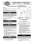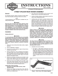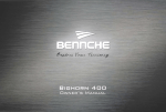
1
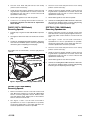
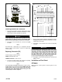
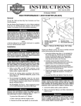
INSTRUCTIONS
®
REV. 1-17-01
-J01208
Kit Numbers: 67017-94C and see below
REPLACEMENT 5 in. ELECTRONIC SPEEDOMETER KITS
General
i01338-.
These speedometer replacement kits are for FLHR/I, Softail
and FXDWG models with the following calibrations:
Kit number
Year and Calibration
67017-94C ..........1994 FLHR, Japan/Canada (Kilo)
67027-96C ..........1996-1998 Softail, Domestic (Mile)
67030-96C ..........1996-1998 Softail, HDI (Kilo)
67033-94C ..........1994 FLHR, Domestic (Mile)
67033-95D ..........1995-1998 FLHR, Domestic (Mile)
67178-95C ..........1995-FXDWG, Domestic (Mile)
67178-96C ..........1996-1998 FXDWG, Domestic (Mile)
67179-95C ..........1995-1998 FXDWG, HDI (Kilo)
67196-94D ..........1994-1998 FLHR, Great Britain (Dual)
67197-94D ..........1994-1998 FLHR, HDI (Kilo)
67255-95C ..........1995 FXDWG, Japan/Canada (Kilo)
67256-95C ..........1995-1998 FXDWG, Great Britain (Dual)
67276-94C ..........1994-FLHR, Swiss (Kilo)
67282-96C ..........1996-1998 Softail, Great Britain (Dual)
67301-95C ..........1995 FXDWG, Swiss (Kilo)
See Service Parts lists for kit contents.
Removing Old Speedometer
NOTE
Locate and follow procedure in this Instruction Sheet that
applies to motorcycle requiring speedometer replacement.
1WARNING
To protect against shock and accidental start-up of vehicle, disconnect the battery cables, negative cable first,
before proceeding. Inadequate safety precautions could
result in death or serious injury.
Figure 1. Cutting Wires At Old Speedometer
4604
Latch
1WARNING
Always disconnect the negative battery cable first. If the
positive battery cable should contact ground with the
negative cable installed, the resulting sparks may cause
a battery explosion which could result in death or serious
injury.
FLHR/I (1994-1996 Models)
Removing Speedometer
1.
2.
Remove the instrument console acorn nut and mounting
screw (with flat washer). Lift the console from the fuel
tank. Turn the console over and lay it on a shop towel
placed on gas tank.
Lock
ring
Clamp
See Figure 1 and 2. Cut all leads connected to
speedometer as close to speedometer as possible;
except reset switch leads. A new switch with wires connected to speedometer connector is provided.
Figure 2. Old Speedometer
1 of 6
3.
Unscrew reset knob and pull harness from clamp
(remove screw if necessary).
3.
Unscrew reset knob and pull harness from clamp
(remove screw if necessary).
4.
Gently pry the three latches upward to release the lock
ring from back of speedometer. Lift console, remove old
speedometer from top side of console. Discard old
speedometer and lock ring.
4.
Gently pry the three latches upward to release the lock
ring from back of speedometer. Lift console, remove old
speedometer from top side of console. Discard old
speedometer and lock ring.
5.
Retain rubber gasket for use with new speedo.
5.
Retain rubber gasket for use with new speedo.
6.
Continue at “Installing Deutsch Mini Terminals”.
Connector [20] does not need to be replaced on
these models.
6.
Continue at “Installing Deutsch Mini Terminals”. After terminals have been installed, replace connector [20] following
instruction given in “Replacing Connector [20]”.
FLHR/I (1997 & 1998 Models)
Removing Speedo
SOFTAILS (1996-1998 Models)
Removing Speedometer
1.
Perform steps 1-5 given for 1994-1996 FLHR/I on previous
page.
1.
2.
See Figure 3. Remove left side cover and locate connector
[20].
Remove instrument console nut and lift console from
tank. Disconnect connectors [20] and ignition switch connector [33] under console. Remove console from fuel
tank.
2.
3.
Continue at “Installing Deutsch Mini Terminals”. After terminals have been installed, replace connector [20] following
instructions given in “Replacing Connector [20]”.
See Figure 1 and 2. Cut all leads connected to
speedometer as close to speedometer as possible;
except reset switch leads. A new switch with wires connected to speedometer connector is provided.
NOTE
3.
On FLHR/I 1997 & 1998 models, connector [20] must be
replaced.
Unscrew reset knob and pull harness from clamp
(remove screw if necessary).
4.
Gently pry the three latches upward to release the lock
ring from back of speedometer. Lift console, remove old
speedometer from top side of console. Discard old
speedometer and lock ring.
5.
Retain rubber gasket for use with new speedo.
6.
Continue at “Installing Deutsch Mini Terminals”. After terminals have been installed, replace connector [20] following
instruction given in “Replacing Connector [20]”.
i03497.eps
Main harness to
console connector [20]
Figure 3. Replacing Connector [20] FLHR/I 1997-98
FXDWG (1995-1998 Models)
Removing Speedo
1.
Remove instrument console nut and lift console from
tank. Disconnect 12-place (or 14 place 0n 1998 models)
harness connector [20] under console. Remove terminals from ignition switch, making note of wire locations.
Remove console from fuel tank.
2.
See Figure 1 and 2. Cut all leads connected to
speedometer as close to speedometer as possible;
except reset switch leads. A new switch with wires connected to speedometer connector is provided.
-J01208
2 of 6
i01339-.
i01340-.
ELECTRONIC
SPEEDOMETER
W/ BN
W V
O/W GN/
SWITCH INPUT
BK/
Y
TN
GN/
Y
O
BK
PURSUIT INDICATOR
ENGINE LAMP
GND
SPEED
SIGNAL
OUTPUT
SPEED
SIGNAL
INPUT
POWER
BK
[20B]
[39A]
121110 9 8 7 4 3 2 1
12 1110 9 8 7 4 3 2 1
W/GN
BK
BK
W
R
BK
BK/Y
GN/R
BK
O/W
[39B]
FUNCTION/
TRIPOMETER
RESET
SWITCH
SPEED SENSOR
P/N 74429-97
+12VDC
1 2 3
4 5 6 7
8 9
10 11 12
1 2 3
4 5 6 7
8 9
10 11 12
SENSOR
OUTPUT
GROUND
BK
BK
R
W
BK
[65B]
A
B
C
[20A]
R
W
BK
[65A]
O/W
W/
GN/ BN W
V
BK/
Y
TN
GN/ O
BK
Y
BK
Figure 4. Wires At New Speedo.
Installing Deutsch Mini Terminals.
1.
See FLT Service Manual “Deutsch Solid Barrel Contact
Crimping Instructions” and follow instructions to terminate the wires cut when speedo was removed.
1CAUTION
In the following step, make certain ground wire from
speed sensor is inserted in cavity (7) of connector [39B].
Do not mix with speedo ground connected at cavity (10).
2.
See Figure 4. Insert terminals into connector half [39B]
as shown.
Figure 5. Wiring Connector [20].
2.
See FLT Service Manual “Deutsch Solid Barrel Contact
Crimping Instructions” and follow instructions to terminate the wires cut in step 1.
3.
See Figure 5. Insert terminals into connector half [20A]
as shown.
NOTE
On FLHR/I 1994 - 1996 models, go to “Installation and Final
Check”. On all other models, continue at “Replacing
Connector [20].
Replacing Connector [20]
NOTE
Connector [20] is located as follows:
FLHR/I - behind left side cover
FXDWG and Softails - under console
1.
Cut wires from main harness (pin connector half [20A])
as close to connector housing as possible.
1CAUTION
To avoid miswiring the indicator lamp wires in the socket
half of the connector in the following step, cut each wire
separately, strip wire, install new socket terminal and
insert terminal in same position that it was in old socket
half. On FLHR/I models switch the check engine light
lead, BK/Y, from cavity (14) in old connector [20] to cavity (7) in new connector [20 ] as shown in Figure 5.
4.
See Figure 5. Insert socket terminals into connector half
[20B] as shown.
Installation and Final Check
All Models
NOTE
The 1998 FLHR/I and FXDWG models have a 14 place connector [20]. Cavities (13 & 14) are not used on FXDWG models. On
FLHR/I models switch the check engine light lead, BK/Y,
from cavity (14) in old connector [20] to cavity (7) in new
connector [20 ] as shown in Figure 5.
-J01208
Apply window cleaning fluid to speedo gasket to aid
assembly.
3 of 6
FLHR/I (1994-1996 Models)
3.
Turn the console over. Place the lock ring over the back
of the speedometer aligning the two slots with the console bosses. Press the latches down until they lock into
position.
1.
Place the gasket into position around the console
speedometer bore.
2.
Fit the speedometer into the bore so that it fits snugly
against the rubber gasket.
4.
Insert the function/reset switch through the hole in the
left side of the console and screw on the rubber button.
3.
Turn the console over. Place the lock ring over the back
of the speedometer aligning the two slots with the console bosses. Press the latches down until they lock into
position.
5.
See Figure 4. Check that new connector [39B] is wired
as shown in Figure 4. Plug connector [39B] into speedo.
6.
See Figure 5. Check that new connector [20] is wired as
shown in Figure 5. Insert seal pins in any cavities not
being used.
7.
Plug connector [20] halves together. On FXDWG, install
ignition switch terminals in original locations. On Softail
models, install connector [33] to ignition switch.
8.
Turn the console over and center the assembly on the
fuel tank. Install the acorn nut.
4.
Insert the function/reset switch through the hole in the
left side of the console and screw on the rubber button.
5.
See Figure 4. Check that new connector [39B] is wired
as shown in Figure 4. Plug connector [39B] into
speedometer.
6.
Turn the console over and center the assembly on the
fuel tank. Install the acorn nut and console mounting
screw (with flat washer).
1WARNING
Always connect the positive battery cable first. If the
positive cable should contact ground with the negative
cable installed, the resulting sparks may cause a battery
explosion which could result in death or serious injury.
7.
Connect battery cables, positive cable first.
8.
Check speedometer for proper operation and clear
diagnostic codes following instructions at end of this
Instruction Sheet.
FLHR/I (1997 & 1998 Models)
1.
Perform steps 1 through 6 from previous “FLHR/I - 1994
- 1996” procedure.
2.
See Figure 5. Check that new connector [20] is wired as
shown in Figure 5. Insert seal pins in any cavities not
being used.
3.
Plug connector [20] halves together and install left side
cover.
1WARNING
Always connect the positive battery cable first. If the
positive cable should contact ground with the negative
cable installed, the resulting sparks may cause a battery
explosion which could result in death or serious injury.
4.
Connect battery cables, positive cable first.
5.
Check speedometer and indicators for proper operation
and clear diagnostic codes following instructions at end
of this Instruction Sheet.
FXDWG (1995 1998 Models)
SOFTAILS (1996 1998 Models)
1.
Place the gasket into position around the console
speedometer bore.
2.
Fit the speedometer into the bore so that it fits snugly
against the rubber gasket.
-J01208
1WARNING
Always connect the positive battery cable first. If the
positive cable should contact ground with the negative
cable installed, the resulting sparks may cause a battery
explosion which could result in death or serious injury.
9.
Connect battery cables, positive cable first.
10. Check speedometer and indicators for proper operation
and clear diagnostic codes following instructions at end
of this Instruction Sheet.
Clearing Diagnostic Codes
The diagnostic mode is entered by turning the ignition from
OFF to ON while holding the reset switch in. The normal
power-up sequence will occur before entering the diagnostic
mode. Diagnostic codes set during this power-up sequence
will be stored as well.
When in the diagnostic mode the odometer will display the
first diagnostic code. When the trip switch is pressed again
the next code will be shown. If the trip switch is pressed for
more than 5 seconds at any time while in the diagnostic
mode, the diagnostic code displayed will be cleared.
1.
Turn the ignition from OFF to ON while holding the reset
switch in.
2.
The code “d01Clr” will be displayed.
3.
Press button again and do not release button “d02SEt”
will be displayed. Hold button in until “d02CLr” is displayed. This indicates code has been cleared.
The diagnostic mode is exited either by turning ignition from
ON to OFF to ON again without depressing the reset switch
or if a speed signal greater than 5 MPH is detected.
For diagnostic procedures, refer to the applicable Service
Manual.
NOTE
A Service Manual for your model vehicle is available from
your local Harley-Davidson dealer.
4 of 6
®
Service Parts
Part No. 67017-94C & others
Replacement Speedometers
Kit Number 67017-94C
Kit Number 67178-96C
Qty.
1
1
1
Qty.
1
1
1
1
1
1
1
6
4
Description
Part No.
Calibrated speedometer
67017-99A
Speedo. back clamp (lock ring)
67271-99
Speedometer harness kit
67440-99
67440-99-Speedometer harness kit contents
Reset switch assembly
67425-98
Boot, reset switch
67880-94
Socket housing, 12 way DTM
74119-98BK
Socket lock
74159-98
Socket terminal, solid
74193-98
Seal pins
74195-98
1
1
1
1
1
1
12
20
8
Description
Part No.
Calibrated speedometer
67027-99A
Speedo. back clamp (lock ring)
67271-99
Speedometer harness kit
67418-99
67418-99-Speedometer harness kit contents
Reset switch assembly
67425-98
Boot, reset switch
67880-94
Pin housing, 12 way DTM
74109-98BK
Socket housing, 12 way DTM
74119-98BK
Pin lock
74149-98
Socket lock
74159-98
Pin terminal, solid
74192-98
Socket terminal, solid
74193-98
Seal pins
74195-98
Qty.
1
1
1
Description
Calibrated speedometer
Speedo. back clamp (lock ring)
Speedometer harness kit
See above for 67418-99 kit contents
Qty.
1
1
1
Description
Calibrated speedometer
Speedo. back clamp (lock ring)
Speedometer harness kit
See above for 67440-99 kit contents
Qty.
1
1
1
Description
Calibrated speedometer
Speedo. back clamp (lock ring)
Speedometer harness kit
See above for 67418-99 kit contents
Description
Calibrated speedometer
Speedo. back clamp (lock ring)
Speedometer harness kit
See above for 67418-99 kit contents
-J01208
Description
Calibrated speedometer
Speedo. back clamp (lock ring)
Speedometer harness kit
See above for 67418-99 kit contents
Kit Number 67255-95C
Part No.
68910-99A
67271-99
67440-99
Kit Number 67256-95C
Qty.
1
1
1
Qty.
1
1
1
Part No.
67033-99A
67271-99
67418-99
Part No.
68911-99A
67271-99
67418-99
Part No.
68179-99A
67271-99
67418-99
Part No.
67196-99A
67271-99
67418-99
Description
Calibrated speedometer
Speedo. back clamp (lock ring)
Speedometer harness kit
See above for 67418-99 kit contents
Description
Calibrated speedometer
Speedo. back clamp (lock ring)
Speedometer harness kit
See above for 67418-99 kit contents
Part No.
67197-99A
67271-99
67418-99
Part No.
67255-99A
67271-99
67418-99
Part No.
67256-99A
67271-99
67418-99
Kit Number 67276-94C
Qty.
1
1
1
Kit Number 67178-95C
Qty.
1
1
1
Description
Calibrated speedometer
Speedo. back clamp (lock ring)
Speedometer harness kit
See above for 67418-99 kit contents
Part No.
67030-99A
67271-99
67418-99
Kit Number 67033-95D
Qty.
1
1
1
Description
Calibrated speedometer
Speedo. back clamp (lock ring)
Speedometer harness kit
See above for 67418-99 kit contents
Kit Number 67197-94D
Kit Number 67033-94C
Qty.
1
1
1
Part No.
67178-99A
67271-99
67418-99
Kit Number 67196-94D
Kit Number 67030-96C
Qty.
1
1
1
Description
Calibrated speedometer
Speedo. back clamp (lock ring)
Speedometer harness kit
See above for 67418-99 kit contents
Kit Number 67179-95C
Kit Number 67027-96C
Qty.
1
1
1
Date 1/01
Description
Calibrated speedometer
Speedo. back clamp (lock ring)
Speedometer harness kit
See above for 67440-99 kit contents
Part No.
67276-99A
67271-99
67440-99
Kit Number 67282-96C
Qty.
1
1
1
Description
Calibrated speedometer
Speedo. back clamp (lock ring)
Speedometer harness kit
See above for 67418-99 kit contents
Part No.
67282-99A
67271-99
67418-99
5 of 6
®
Service Parts
Part No. 67301-95B
Date 1/01
Replacement Speedometers
Kit Number 67301-95C
Qty.
1
1
1
1
1
1
1
1
1
12
20
8
Description
Part No.
Calibrated speedometer
67301-99A
Speedo. back clamp (lock ring)
67271-99
Speedometer harness kit
67418-99
67418-99-Speedometer harness kit contents
Reset switch assembly
67425-98
Boot, reset switch
67880-94
Pin housing, 12 way DTM
74109-98BK
Socket housing, 12 way DTM
74119-98BK
Pin lock
74149-98
Socket lock
74159-98
Pin terminal, solid
74192-98
Socket terminal, solid
74193-98
Seal pins
74195-98
-J01208
6 of 6