1
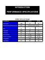
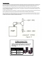
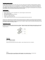
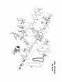
DURAVAC “RP” SERIES Oil Lubricated, Rotary Piston Vacuum Pumps Models RP-35 & RP-50 INSTALLATION OPERATION MANUAL WARNING DO NOT OPERATE BEFORE READING MANUAL US VACUUM PUMPS LLC P.O. BOX 909 CANTON, TX USA 75103 TEL: 888-416-7366 FX: 877-416-7599 EMAIL: [email protected] WWW.USVACUUMPUMPS.COM FORWARD This manual contains installation, operation, maintenance and troubleshooting information for the Model RP-35 & RP-50 Rotary Piston Vacuum Pumps. Please read it in its entirety before operating the pump. Our Rotary Piston Vacuum Pumps are designed to ensure safety when used properly. It is the responsibility of the user to follow safety-related warnings, cautions, notes and other requirements described in this manual. Returned equipment will not be accepted by our company without prior authorization. Prior to shipping please call for a returned goods authorization number (RGA). Our company reserves the right to cancel the warranty if the pump is disassembled without authorization, if pump fluids are used that are not compatible with the design and materials used in the manufacturer of the pump, and if unauthorized spare parts are used. WARNING The pumps associated with this manual use industrial systems including heavy Current/Voltage installations. Depending on the operating conditions, particularly where dangerous conditions may be present, improper handling could lead to severe personal injury or property damage. Those responsible for safety of the installation must therefore insure that: ONLY QUALIFIED PERSONNEL ARE ALLOWED TO WORK ON THE MACHINE(S). THESE PERSONS ALWAYS HAVE AT THEIR DISPOSAL THE SUPPLIED OPERATING INSTRUCTIONS AND OTHER PRODUCT DOCUMENTATION WHEN DOING SUCH WORK, AND THEY UNDERTAKE TO FOLLOW ANY SUCH INSTRUCTIONS CONSTANTLY. NONQUALIFIED PERSONNEL ARE NOT PERMITTED TO WORK ON OR NEAR THE MACHINE(S). ALL WORK DONE ON ANY ELECTRICAL DEVICES AND ASSOCIATED EQUIPMENT ( including motors, control panels, circuit panels, etc) MUST PERFORMED BY A PROPERLY TRAINED AND CERTIFIED ELECTRICAN. THE WARNINGS, CAUTIONS, AND INSTRUCTIONS DISCUSSES IN THIS MANUAL CANNOT COVER ALL POSSIBLE CONDITIONS AND SITUATIONS THAT MAY OCCUR. IT MUST BE UNDERSTOOD BY THE OPERATOR THAT COMMON SENSE AND CAUTION ARE FACTORS THAT CANNOT BE BUILT INTO THIS PRODUCT, BUT MUST BE SUPPLIED BY THE OPERATOR. SAFETY PRECAUTIONS CAUTION: When using PVC pipe or any static enhancing material for exhaust piping, make provisions to safeguard against arcing from static electricity. Arcing can ignite oil vapor that may be present. CAUTION: Do not operate the pump without the belt guard properly attached. Operating the pump without the belt guard secured in place exposes people in the vicinity of the pump to risk from rotating drive parts. CAUTION: Do not operate this pump in oxygen service. Oxygen service is defined as any application which has a process gas concentration that exceeds 20%. Pumping oxygen enriched gases with mineral oil or other non-inert fluids can cause an explosion in the pump, resulting in damage or injury. CAUTION: Take precautions to avoid prolonged or excessive exposure to oil mist or process materials from the discharge of the pump. Do not discharge the pump into a closed room or a room without adequate ventilation. Always use a discharge oil mist eliminator unless the pump discharge is vented to the open air. Venting the outlet to open air is highly recommended CAUTION: Disconnect the pump from the electrical supply at the main disconnect before dismantling or servicing the pump. CAUTION: Lift only with the lifting eyebolts supplied with the pump. Do not lift equipment attached to the pump with the eyebolts supplied. CAUTION: Do not restrict the pump discharge line in any way, or place any valves in the discharge line. Excessive pressure build-up could cause damage or injury. CAUTION: Do not touch hot surfaces on the pump. In normal operation at low pressures surface temperatures will not normally exceed 160 Degree F. Prolonged operation at 200 torr may cause surface temperatures up to 200 Degree F. TABLE OF CONTENTS SAFETY PRECAUTIONS…………………Page 2 INTRODUCTION…………………...………Page 4 PERFORMANCE SPECIFICATIONS…….Page 6 DESCRIPTIONS…………………………….Page 7 GENERAL INFORMATION……….………..Page 8 START-UP……………………………………Page 10 TROUBLESHOOTING………………...……Page 11 PARTS LIST & EXPLODED VIEWS………Page 15 WARRANTY STATEMENT…………….......Page 21 INTRODUCTION CONGRATULATIONS on your purchase of a new Duravac “RP” Series OIL LUBRICATED, Rotary Piston Vacuum Pump from US VACUUM. Please examine the pump for shipping damage, and if any damage is found, report it immediately to the carrier. If the pump is to be installed at a later date make sure it is stored in a Clean, dry location and rotated regularly. Make sure covers are kept on all openings. If pump is stored outdoors be sure to protect it from weather and corrosion. DURAVAC vacuum pumps are built to exacting standards and if properly installed and maintained will provide many years of reliable service. We urge you to take time to read and follow every step of these instructions when installing & maintaining your pump. WARNING: Serious injury can result from operating or repairing this machine without first reading the service manual and taking adequate safety precautions. IMPORTANT: Record the pump model and serial number in the OPERATING DATA form below. You will save time and expense by including this reference information on any replacement parts orders. OPERATING DATA It is to the user’s advantage to have the requested data filled in below and available in the event a problem should develop in the vacuum pump. This information is also helpful when ordering spare parts. Model No____________________________ Oil Type________________________________ Serial No.____________________________ Operating Vacuum________________________ Startup Date__________________________ Inlet Gas Composition_____________________ Motor Hp_____________ RPM____________ Accessories supplied______________________ NOTES:____________________________________________________________________________________ ___________________________________________________________________________________________ ___________________________________________________________________________________________ ___________________________________________________________________________________________ ___________________________________________________________________________________________ ___________________________________________________________________________________________ ___________________________________________________________________________________________ ___________________________________________________________________________________________ ___________________________________________________________________________________________ ___________________________________________________________________________________________ ___________________________________________________________________________________________ ___________________________________________________________________________________________ ___________________________________________________________________________________________ PRINCIPLE OF DESIGN The Duravac RP-35/50 series of pumps are of the cam (eccentric) and piston (Slide) type and are Duplex in design. Within the pump, the piston is driven by the cam. The cams are mounted 180 degrees apart on a single shaft so that centrifugal forces of the moving pistons will oppose one another. The shaft passes through the center wall separating the two pump sections and is supported by bearings in the heads at each end of the cylinder. The open head which the shaft extends, has a shaft seal set-up to prevent air leakage into the pump and an outboard bearing to handle the belt pull force. The driven pump pulley is weighted to provide for final pump balancing Each piston has an integral hollow extension (called a slide) which extends through the slide pin (hinge bar). One side of the slide contains diagonal slots; as the slide passes back and forth through the slide pin, these slots are covered and uncovered to form an inlet valve. Outlet valves are over the discharge port on top of the cylinder. All working parts are precisely machined to suitable clearances for high vacuum requirements. The covering and uncovering of the slots in the piston slide by the slide pin constitutes a mechanical inlet valve. Air of gas is admitted Through these slots from the high vacuum side of the slide pin into the space between the piston and cylinder at certain parts of the cycle. As there is no spring loading, no pressure difference is required to operate this valve. The outlet (discharge) valve is opened automatically by the compression of the air or gas in the pump against atmospheric pressure, plus a slight spring pressure. Since the success of the pump depends on its being sealed and lubricated, an oil reservoir is mounted above the pump. The sealing oil needs to be free from gases or moisture. Otherwise, the vapors will be pulled out of the oil (outgassing) and will prevent obtaining low absolute pressures. In view A from the figures below, the piston is moving in the direction of the arrow and is rapidly creating more space into which some of the gas is admitted through the inlet port; at the same time, view B is compressing the gas previously trapped and is taking place on the opposite side of the piston. As the piston reaches the end of it’s compression cycle in view B, it expels all the air or gas and surplus sealing oil through the outlet valve and into the oil reservoir tank. The reservoir tank is where the oil is retained for recirculation and the air or gas being pumped is expelled out the discharge port of the reservoir. EXHAUST OIL SEPARATOR OIL DISCHARGE VALVE PISTON INLET SLIDE PIN CAM Fig-1 INTRODUCTION PERFORMANCE SPECIFICATIONS SPECIFICATIONS Pump Model Displacement CFM Ultimate Vacuum (Partial pressure) Torr Motor RP-35 RP-50 37 52 10 microns (0.010 mm Hg) Hp 1.5 2 Pump Speed RPM 400 550 Oil Capacity Gal 2 2 Inlet connection in. 2" Flg 2" Flg Exhaust connection in. 1.5" NPT 1.5" Flg AIR AIR 380 385 Cooling Media Pump Weight Lbs. GENERAL UNPACKING Inspect the box and pump carefully for any signs of damage incurred in transit and report with-in 7 days of receipt. Since all our pumps are shipped F.O.B. our factory, such damage is the responsibility of the carrier and reported to them. The inlet & exhaust of the pumps are covered with plastic caps to prevent dirt and other foreign substances from entering the pump. Leave the caps in place until you are ready to pipe the pump to your equipment. LOCATION Locate the pump as near as possible to the equipment being evacuated so that the vacuum, water and exhaust connections can be conveniently made. Leave 12-18” of access around the pump to allow proper access for routine maintenance. Allow access to the oil sight glass in order to inspect the oil level and for easy access to change the lubricating oil and exhaust filter. INSTALLATION The pump should be mounted on a rigid foundation, such as a concrete floor. The pumps come with four (4) rubber vibration dampening supports to be mounted (bolted) onto each corner of the pump. The pumps can operate without foundation securing. Remove cap from exhaust and intake openings only when ready to make pipe connection. When the pump is to be subjected to temperatures below freezing, drain water jacket through the housing drain plug to prevent cracking the housing, then blow out water jacket with compressed air. Follow this same procedure for storage Cooling water: The pumps are AIR COOLED and do not require cooling water for operation. The pumps are designed to operate up to a maximum ambient temperature of 110 Deg F. VACUUM CONNECTION All pipe lines should be as short as possible and should be no smaller in diameter than the inlet to the pump….if it is absolutely necessary to run a long line, the suction pipe should be increased 50% in diameter. Conductance of long lengths of suction piping must be checked and the line sized large enough so the pumping speed of the system will not be seriously affected. Pumps operating in parallel on a common main line should have a manual or automatic shut-off valve or positive acting check valve installed in the suction line of the pump. Should the process gas contain dust of other foreign material, a suitable inline particulate filter should be connected to the inlet port…..contact US Vacuum for recommendations. When connecting the pump to the system, provide proper piping geometry to prevent dirt from the system from entering the pump and to prevent back siphoning of pump oil in the system chamber. The vacuum piping should be designed to insure that no liquids such as condensate or liquid carryover from the process can reach the pump. If this possibility exists, a knock-out liquid separator should be installed…..contact US Vacuum for recommendations. The best piping for the vacuum side of the pump is made up with flanges using neoprene/fiber gaskets or O-rings. Flanges may be welded or threaded to pipe. If threaded connections are used, use a heavy sealing compound to insure no leaks are present. CAUTION: Make sure the system to be evacuated and connecting lines are clean and free of weld splatter, dirt, or grit. Foreign matter entering the pump can cause failure and possibly damage the internal parts, VACUUM CONNECTION (cont.) Typical piping arrangement for pump mounted below system (Fig-2) and for the pump mounted above the system (Fig-3) TYPE OF PIPE JOINTS A) Standard steel piping with welded joints makes the best vacuum piping system. B) Copper piping with sweated fittings and joints can also made vacuum tight and has the advantage of providing a neat, clean vacuum installation. C) Standard threaded piping, however, is satisfactory and more readily installed. The piping should be Carefully cleaned to remove any scales or chips. Blow out any loose material with compressed air prior to installation. All male threaded joints should be carefully doped, screwed up tight and NEVER “backed-off” to make parts align-this is apt to cause a leak. Paint the joints while the system is under vacuum with a vacuum grade sealant until the sealant is no longer drawn into the piping threads. U.S. Vacuum Sealant should be used.. DISCHARGE PIPING It is recommended that the exhaust be piped horizontally a short distance and tied into a vertical exhaust pipe. The vertical exhaust pipe must be at least 1 ft. long and the bottom end of the vertical exhaust pipe be terminated with a plug or drain valve to allow removal of moisture and contaminated oil before it can accumulate sufficiently to drain back into the pump oil reservoir. The exhaust pipe should be no smaller than the pump exhaust outlet and as short as possible. Run the pipe outside the building or into a coalescing Oil mist filter. When pumping noxious or toxic gases, the exhaust must be vented outside the building even if a discharge oil mist filter is installed. The pump exhaust should have a horizontal run to a drop-out Tee, and then go up if necessary. Equip the Tee with a drain valve to drain off condensate from time to time as needed. Oil mist eliminator filters are available to replace the piping. When starting the pump or handling large amounts of air, oil vapor in the form of smoke will exit the pump exhaust port. This is no indication of trouble, as the volume of smoke will decrease as the volume of air reduces and the vacuum in the system improves. OIL EXHAUST FILTERS are available to alleviate exhaust smoke. Oil Mist exhaust Filter Used to eliminate (99%) of the oil mist from the pump discharge. High efficiency coalescing technology Pump Model Cat. No RP-35 VFSG484150 RP-50 VFSG848150 ELECTRICAL CONNECTIONS A schematic diagram for the electric motor terminal box is located either inside the junction box cover or on the side of the motor itself. The motor must be connected according to applicable electrical codes Through a fused switch in order to protect the motor against electrical or mechanical overload conditions. The overload of the motor starter must be set at a level equal to the full load motor current listed on the nameplate. Wire the solenoid valve to allow oil flow from the pump oil reservoir to the pump bearings & internals. AFTER ELECRICAL CONNECTIONS HAVE BEEN MADE, BUT PRIOR TO FILLING THE PUMP WITH OIL, THE ROTATION OF THE MOTOR SHOULD BE CHECKED. IF BACKWARD, REVERSE ANY TWO LEADS OF THE THREE AT THE POWER CONNECTION. COOLING The pumps are AIR COOLED and do not require cooling water for operation. The pumps are designed to operate up to a maximum ambient temperature of 110 Deg F. CAUTION: Do not start the pump when oil temperature is below 55 Deg F. Excessive wear and galling damage to the moving parts may occur OIL FILLING The successful operation of this pump depends largely on the type of oil used. An initial charge of oil is included with each pump. This standard oil is US350-H which is recommended for general operating in a relatively clean environment. After level installation and correct rotation of the pump has been established, fill the pump with recommended oil through the oil fill port. Oil level should be at the 3/4 position on the sight glass window. Oil capacity: 2 Gallons CHANGE OIL EVERY 500-750 OPERATING HOURS Check the oil for contamination on a weekly basis by shutting the pump off and draining some of the oil into a small glass or container through the oil drain port. Oil life is dependent upon the condition to which it is exposed. The oil must be changes after the first 100 hours of initial operation. After the initial oil change, and when using US350-H, it is recommended that the oil changes are made every three (3) or four (4) months or 500-750 hours of operation, or as necessary if high heat is contaminating the oil. To change the pump oil, the pump must be switched off and ventilated to reach atmospheric pressure. Open the oil drain valve and drain the oil. Dispose of the oil in compliance with local or national regulations. When oil stops draining, replace the oil drain plug. Start the pump again for a few seconds. Stop the pump once again, and then reopen the oil drain valve and discharge any remaining oil. Refill with new oil. Optimum pump oil temp. should be between 140-160 Def F. EXCESSIVE HEAT: When the pump is subjected to operating conditions that will cause the oil to be heated above 200 Deg F, the oil will carbonize and become contaminated after a relatively low number of operating hours if standard hydrocarbon oil is used. The higher the temperature, the quicker the oil becomes contaminated and thermally breaks down. In these type of high heat applications, US550SS oil is recommended. CONTAMINATED AIR STREAM When the air stream contains solids and/or liquids that may contaminate the oil, the oil must be changed more often. If the air stream contains a small percentage of particulate matter, the solution is to install a pre-filter or knock-out pot to keep the contaminates out of the pump. START-UP 1) Be sure the suctions lines are free of foreign matter and perfectly tight. Use inlet protection screens or drop-out traps on new installations where large welded piping is employed. 2) Make sure the pump discharge is not obstructed 3) Check that the cooling water is connected to the pump and available (If required) 4) Check belt tension. Deflection should be 1/2” at the center (midway) span of the belt 5) Check the oil level and adjust if necessary 6) Ensure that the oil line solenoid is wired correctly and oil is flowing CAUTION: If the oil flow indicator ball does not rise, stop pump immediately. - Check operation of solenoid - Check oil lines for blockage 6) Check for correct rotation of the pump. 7) Ensure the suction line is not under vacuum (at atmospheric pressure) 8) Close the vent valve if one is used 9) Start the pump 10) Turn on cooling water and adjust flow according to previous instructions 11) Adjust gas ballast as required . STOPPING THE PUMP To stop the pump: 1) Close the isolation valve in the suction line 2) Vent the pump to atmosphere thru vent valve or gas ballast valve 3) Stop the pump 4) Turn off cooling water NOTE: Venting the pump prior to shutdown returns the lubricating oil in the pumping chamber back to the oil reservoir and prevents the pump from rotating backwards. Failure to follow proper shutdown Procedures can result in both hydraulic and vacuum locking the pump and possibly causing pump damage. GAS BALLAST The gas ballast valve is a manual valve located on the endplate. The valve introduces atmospheric air into the pumping chamber to aid in removing condensable vapor contaminates from the vacuum pump oil. Vapor contaminates in the pump oil can dramatically impair the pump performance by vaporizing during the low pressure section of the pumping cycle thereby preventing gas from being drawn into the pump. Isolate the pump from the system and fully open the gas ballast valve and run the pump overnight. If this is not possible, partially open the valve during operation and run until oil is clean. CAUTION: Gas ballast should NEVER be used if vapors being pumped are explosive, (ie: methane gas, hydrogen and certain solvent vapors) When gases of an explosive nature are being handled, the safest procedure is to remove the gas ballast valve entirely and plug or cap the pipe to which the gas ballast valve is attached. Opening the gas ballast valve slightly will quite valve noise when pump is blanked-off. SOLENOID VALVE The solenoid valve feeds oil from the upper oil reservoir to the pumping cylinder via an oil line feeding each endplate. The solenoid is N.C. (normally closed) and is used to keep oil in the upper reservoir from draining into the pump cylinder when the pump is not in operation, thereby preventing oil from filling up the cylinder. Restarting the pump with the cylinder filed with oil can cause hydraulic lock and damage to the pump. Make sure to check the voltage requirements on the solenoid and that it is wired accordingly. Low or incorrect voltage will cause the valve not to open and lead to a loss of oil lubrication to the pump causing severe damage to the pump. Hot smell or smoke from the solenoid is cause for investigation. Do not energize the coil when it is removed from the valve body, this will cause the coil to fail. SOLENOID VALVE (CON”T) Foreign matter will cause the valve to stick, jam or leak. Any solenoid valve should be cleaned periodically. Solenoid valves should be cleaned when the oil is changed due to contamination by foreign matter. Solenoids are designed for use in relatively dry locations and in temperatures up to 115 Degree F. Weather-proof and special purpose solenoids are available. There is always a slight hum when the solenoid is working; a slight click will be heard when the solenoid opens properly as the core hits the plug at the tope of the core tube. MAINTENANCE Periodic Maintenance DAILY: Visually check oil level in sight glass & color, oil flow through the solenoid & oil lines Weekly: Check inlet filter Every 3 Months/ 500-750 hours– Change oil 3000 Hours– Change exhaust filter. Replace V-belt and Discharge valves 10,000– Replace bearings and seals. This is to be done by specially trained service personnel. Change oil every 500-700 hours or as needed. Clean oil reservoir housing every 1000 hours to increase the life of the lubricating oil. Darkening of the pump oil indicates pump wear or chemical reaction between the oil and the gases being pumped. White milky oil is an indication of water contamination...use gas ballast to clear oil or change oil. Water can also be removed by draining water from the pump (oil drain valve) before starting the pump. DISCHARGE VALVES Discharge valves are located inside the oil reservoir, under the oil baffle & valve plate. After draining oil from the pump, remove valve assembly by removing the six (6) cap screws and valve gasket….inspect valve discs (26C), seat (26D) and springs (26B) for wear. Change if required. Repair kits RP-35: Pt#RKIT-RP35-RKIT RP-50: Pt#RKIT-RP50-RKIT Repair Kit includes bearings, shaft seals, gaskets, o-rings, discharge valves & misc. hardware . NOTE: US Vacuum Pumps LLC is not liable for operational failure due to mistakes made by non-US Vacuum personnel during the installation/operation or the utilization of non-US Vacuum parts TROUBLESHOOTING Before attempting to locate the cause of the of poor ultimate pressure, check the accuracy of the vacuum gauges on the system. TROUBLE The pump does not reach “blank-off” pressure or takes too long to evacuate the system. Possible cause: The internal parts are worn or damaged. Remedy: Contact U.S. Vacuum for instructions. Possible cause: Contaminated oil is the most common cause of not reaching ultimate pressure. TROUBLE Remedy: Shut off the pump, after the operating temperature has been reached, drain the warm oil from the pump. Flush and fill the pump with new oil and take a new “blank off” measurement after operating temperature is reached (20-30 minutes). The pump is excessively noisy Possible cause: Solenoid valve not opening properly or inoperative.. Possible cause: Poor or no oil lubrication Remedy: Check and clean valve or replace coil. Possible cause: Typical noise at high vacuum Remedy: Open gas ballast valve Remedy: Check solenoid valve/coil, replace if required. Check oil lines for blockage, clean or replace. Possible cause: Loose intake flange or head bolts Remedy: Tighten bolts TROUBLE Possible cause: No oil or not enough oil in the oil reservoir. The pump will not start Possible cause: Motor overloads tripping out Remedy: Shut off the pump, add the necessary oil, or if oil seems contaminated, drain the balance of the oil from the pump, exchange oil filter and refill with fresh oil. Flush if necessary. Remedy: Check overload settings Vs motor nameplate value. If necessary use 1 size larger thermal overload Possible cause: Oil line connection leaking Possible cause: Possible internal seizure Remedy: Tighten if necessary Remedy: Disassemble and correct Possible cause: Exhaust valve not sealing. TROUBLE Remedy: Disassemble and clean if necessary. Possible cause: Threaded connections leaking The pump will not turn over when motor starts Remedy: Paint with vacuum sealant Possible cause: Belts too loose Possible cause: Shaft seal leaking Remedy: Tighten V-belts Remedy: Inspect and replace if necessary Possible cause: Cylinder may be flooded with excessive oil due to defective solenoid valve (stuck in open position). TROUBLE Pump runs hot Remedy: Turn pump over by hand to remove excessive oil. Check solenoid valve, clean or replace Possible cause: Oil temperature too low, or viscosity too high. Remedy: Warm up oil, use ISO100 oil. Possible cause: Water temperature or flow inadequate Remedy: Check water flow to pump. Increase flow is necessary. Check that the water jacket is not clogged with mineral deposits or scale. Clean is necessary TROUBLE Possible cause: No oil flow to pump. Possible cause: Pump turns backwards for several revolutions when motor turned off. Remedy: Close gas ballast valve before shutting off pump. This prevents atmospheric air from reversing direction of pump piston when power is off. TROUBLE Pump smokes at the exhaust side or expels oil droplets from the exhaust Possible cause: No exhaust filter in place Remedy: Install exhaust filter Possible cause: The exhaust filter is not properly seated with the o-ring in filter base or filter material is cracked. Remedy: Exhaust filter not properly seated with oring, replace if necessary. Check element and secure Possible cause: The exhaust filter is clogged with foreign particles. Remedy: Replace the exhaust filter. Remedy: Check solenoid valve-clean or replace as necessary. RP‐35/50 EXPLODED VIEW MODEL RP-35/50 Parts List WARRANTY– VACUUM PRODUCTS Subject to terms and conditions hereinafter set forth and set forth in General Terms of Sale, US Vacuum Pumps LLC (the seller) warrants products of its manufacturer, when shipped, and its work (including installation & start-up) when performed, will be of good quality and will be free from defects in material and workmanship. This warranty applies only to sellers equipment, under use and service in accordance with seller’s written instructions, recommendations and ratings for installation, operating, maintenance and service of products for a period if 12 months. Because of varying conditions of installation and operation, all guarantees of performance are subject to plus or minus 5% variation. THIS WARRANTY EXTENDS ONLY TO BUYER AND/OR ORIGINAL END USER, AND IN NO EVENT SHALL THE SELLER BE LIABLE FOR PROPERTY DAMAGE SUSTAINED BY A PERSON DESIGNATED BY THE LAW OF ANY JURISDICTION AS A THIRD PARTY BENEFICIARY OF THIS WARRANTY OR ANY OTHER WARRANTY HELD TO SURVIVE SELLER’S DISCLAIMER. All accessories furnished by seller but manufactured by others (motor) will bear only that manufacturer’s standard warranty. All claims for defective products, parts, or work under this warranty must be made in writing Immediately upon discovery and, in any event within one (1) year from date of shipment of the applicable item by seller. Unless done with prior written consent of seller, any repairs, alterations or disassembly of sellers equipment shall void warranty. Installation and transportation costs are not included and defective items must be held for seller’s inspection and returned to sellers Ex-works point upon request. THERE ARE NO WARRANTIES, EXPRESSED, IMPLIED OR STATUTORY WHICH EXTENDS BEYOND THE DESCRIPTION ON THE FACE HEREOF, INCLUDING WITHOUT LIMITATION, THE IMPLIED WARRANTIES OF MERCHANTABILITY AND FITNESS OF PURPOSE. After buyers submission of a claim as provided above and its approval, seller shall at it’s option either repair or replace its product, part, or work at the original Ex-works point of shipment, or refund an equitable portion of the purchase price. The products and parts sold hereunder are not warranted for operation with erosive or corrosive materials or those which may lead to a build-up of material within the product supplied, nor those which are incompatible with the materials of construction. The buyer shall have no claim whatsoever and no product or part shall be deemed to be defective by reason of failure to resist erosive or corrosive action nor for problems resulting from build-up of material within the unit nor for problems due to incompatibility with the materials of construction. Any improper use, operation beyond capacity, substitution of parts not approved by seller, or any alteration or repairs by others in such manner as in sellers judgment affects the product materially and adversely shall void this warranty. No employee or representative of seller other than an officer of US Vacuum Pumps LLC is authorized to change this warranty in any way or grant any other warranty. Any such change by an officer of the company must be in writing. In no event shall buyer be entitled to incidental or consequential damages. Any action for breach of this agreement must commence within (1) year after the cause of action has occurred. NOTES