1
(UK/0126/0057)
MI-005
United Kingdom of Great Britain and Northern Ireland
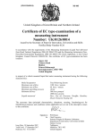
Certificate of EC type-examination of a
measuring instrument
Number: UK/0126/0057
issued by the Secretary of State for Business, Innovation & Skills
Notified Body Number 0126
In accordance with the requirements of the Measuring Instruments (Liquid Fuel delivered
from Road Tankers) Regulations 2006 (SI 2006/1259) and the Measuring Instruments (NonPrescribed Instruments) Regulations 2006 (SI 2006/1270) which implement, in the United
Kingdom, Council Directive 2004/22/EC, this certificate of EC type-examination has been
issued to:
Johann Heidt Developments
Hoobrook Trading Estate,
Kidderminster,
Worcestershire, DY10 1HY
United Kingdom
in respect of a vehicle mounted liquid fuel meter measuring instrument having the following
characteristics:
model designation:
the maximum rate of flow:
the minimum rate of flow:
the minimum delivery:
the maximum operating pressure:
the liquids measured:
Dry Line – Mechanical or Electronic Registers
900 litres/minute
150 litres/minute
500 litres
10 bar
Derv, gas oil, kerosene, paraffin
The necessary data (principal characteristics, alterations, securing, functioning etc) for
identification purposes and conditions (when applicable) are set out in the descriptive annex
to this certificate.
Signatory:
for
Issue Date: 02 July 2009
Valid Until: 01 July 2019
Reference No: T1121/0009
P R Dixon
Chief Executive
National Weights & Measures Laboratory
(Part of the National Measurement Office)
Department for Business, Innovation & Skills
Stanton Avenue
Teddington
Middlesex TW11 0JZ
United Kingdom
Descriptive Annex
1
INTRODUCTION
1.1
The pattern is a meter measuring system fitted to a road tanker for the
transport and delivery of liquids with low viscosity stored at atmospheric pressure. It is
bottom loading, and comprises a pump, a gas extractor or gas separator, a meter, a
mechanical or electronic indicator/calculator/pre-setter, mechanical or electronic compatible
ancillary equipment, and an empty hose reel. Schematic and photographic views of the
system are shown in Figures 1, 2, 3, 4 and 9. The system allows:
(i)
metered delivery by pumping (empty hose) (50 mm)
(ii)
direct unmetered delivery (with or without pumping) without passing through
the meter (70 mm).
A pumped air ‘blowdown’ system is employed to discharge product retained in the hose.
2
CONSTRUCTION
2.1
Mechanical
2.1.1
Hydraulics
The hydraulics system is illustrated in Figure 1, with a key at Section 12 and in Figure 9.
Liquid may flow from any of the selected compartments of the cargo tank via the appropriate
faucet valve. There is the option of unmetered gravity delivery or pumped delivery via a
connecting hose. If pumped delivery is selected, there is the further option of metered or
unmetered delivery. If metered delivery is selected, the liquid flows through a filter, gas
extractor and meter to a 50 mm dry hose reel. The transfer point is at the valve cl2, in
Figure 1, where air for blowdown is injected.
2.1.1.1
(a)
(b)
(c)
(d)
(e)
(f)
(g)
(h)
(i)
(j)
(k)
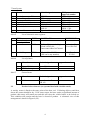
List of pumps
Manufacturer
Model designation
Nominal bore (mm)
Blackmer (Geo Meller)
Drum Engineering Ltd
Drum Engineering Ltd
Drum Engineering Ltd
Mouvex
Orr Pumps
Peerless Pumps
Plenty Mirrlees Pumps
Roper Pump Co
Roper Pump Co
Wade Engineering Ltd
TX and TNP series
FP 65 64
Pluto 3
Mercury 3
CC 20
C 250
Varley
Ropak Series
3600/3700 series
4600/4700 series
Gorman Rupp O2F1
50, 64, 75
64
75
75
64
64
64, 75
50, 75
50, 75
50, 75
50
2
List of gas extractors / gas separators
2.1.1.2
(a)
(b)
(c)
(d)
(e)
(f)
(g)
(h)
Manufacturer
Model designation
Geosource GmbH (Smith)
Actaris Ltd
Liquid Controls (Alpeco)
Tokheim Ltd
Isoil
Satam
Schlumberger
Pernin
Air release and strainer
Series A 8100
1506
FDV 75
EC 30.20
Separator FSG48E
FSGB 48E
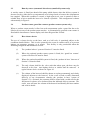
List of gas separators combined with pump
2.1.1.3
(a)
(b)
(c)
EEC pattern
approval number
D79 5.153.01
UK81/1767
UK81/1783
UK81/1791
UK84/1887
UK84/1875
F96.00.522.002.0
F99.00.522.005.0
Manufacturer
Model designation
Blackmer/Mouvex
Blackmer/Mouvex
Blackmer/Mouvex
Mouvex DMX
Mouvex DMX II
Mouvex DMX III
EEC pattern
approval number
F89.0.05.462.1.3
F95.00.522.002.0
F99.00.522.003.0
List of meters
2.1.1.4
50 mm System
Manufacturer
Model designation
(a)
(b)
(c)
(d)
(e)
(f)
(g)
(h)
(i)
Brooks Instruments BV
Dresser Europe SA
Geosource GmbH
Liquid Controls (Alpeco)
Neptune Measurement Ltd
Actaris (was Schlumberger)
Neptune Measurements Ltd
Isoil
Tokheim Ltd
(j)
Satam
(k)
Smith Meters
B1 42
T 50
T 11 or ST 40
M 7, M-15
Type 4 or 40
4(or 40)-MT
NVR45
BM 75 T
1400-20
1450-20
ZC 1720/20
ZC 17 20/40
T.11/ST40
T.20/ST75
T.40/ST160
3
EEC pattern
approval number
NL80 E56
UK80 1722
D80 5.243.10
UK81 1782
UK81 1766
UK97 2459
F89.0.07.422.2.3
D81 5.243.19
UK81 1788
UK81 1789
F77 01.422
F77 07.422
D 1.51.5034/80
75 mm System
Manufacturer
Model designation
(a)
(b)
(c)
(d)
(e)
(f)
Brooks Instruments BV
Dresser Europe SA
Geosource GmbH
Liquid Controls (Alpeco)
Isoil
Tokheim Ltd
(g)
Neptune Measurement Ltd
B 72 DB
T 75
T 20 or ST 75
M 15 or M 25
SBM 150
1400-30
1450-30
Type 4 or 40
EEC pattern
approval number
NL79 E40
UK80 1722
D80 5.243.11
UK81 1782
D79 243.01
UK81 1788
UK81 1789
UK81 1776/1
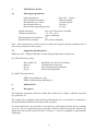
List of electronic meter registers
2.1.1.5
TYPE
SOFTWARE
(a)
ITEM
Electronic register
/control unit
Veeder-Root
EMR3
Edition F04 onwards: Register Evaluation (Test)
Head 349785-001
Cert. GB-1285
Interconnect Box 349784-001
(b)
S.A.M.P.I s.p.a
TE550
SD-001-550-027-XX
(XX can be any number)
NMI Test Cert.
TC3583
List of printers
2.1.1.6
(a)
(b)
Manufacturer
Model designation
Approval number
Epson TM 290
DH Technologies
Epson TM 290
Blaster Printer
-
Manufacturer
Model designation
Approval number
Meller
Power Junction Box
EJB 102
-
General items
2.1.1.7
(a)
2.2
REFERENCE
Product in hose detector (on systems fitted with closable nozzle)
A wet/dry sensor is fitted to the entry point of the hose reel. Following delivery and blow
down, this sensor should be dry. If for some reason, the hose retains a significant amount of
product, this sensor will remain wet and this will cause the vehicle brakes to be locked on.
This condition will pertain until the hose is cleared of product. A schematic view of this
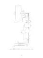
arrangement is shown in Figure 9 (S2).
4
2.3
Run dry sensor (automatic blowdown) (manifold systems only)
A wet/dry sensor is fitted just ahead of the pump which detects when the delivery system is
about to run dry, either due to a compartment valve being closed or because the compartment
has emptied. When this condition is sensed, a high capacity air vent is opened to allow a
suitable flow of air to enable the hose to be cleared of product. This arrangement is shown
schematically in Figure 9.
2.4
Product return guard bar counter (product return systems only)
Where a product return nozzle is fitted on each compartment outlet a guard bar has to be
lifted to access any of the product return nozzles. A pneumatically operated event counter is
fitted which increments a counter display each time the guard bar is lifted.
2.5
Hose closure device
The use of a closure device on the hose, such as a ball valve is permitted subject to the
conditions detailed below. This is to be operated in the event of a tank overfill, or to prevent
leakage on customers property, or in transit. This facility is only permissible when the
following safeguards and conditions are met.
(i)
The ‘product in hose’ system of Section 2.3 must be fitted.
(ii)
Where the optional product return system is fitted, the ‘guard bar counter’
system of Section 2.4 must be fitted
(iii)
Where the optional manifold system is fitted, the ‘product in hose’ detector of
Section 2.3 must be fitted
(iv)
The only closure shall be the valve such that when open, the hose may be
observed to be clear. Anti-siphon devices or similar shall be removed. A
typical closure device is shown in Figure 10.
(v)
The volume of the hosereel shall be shown on a plate permanently and clearly
displayed adjacent to the hosereel. In the event of tank overfill (frustrated
delivery) or any circumstance whereby the ‘product in hose’ system of
Section 2.3 is activated, the customer shall be issued with a credit note for the
full hosereel volume, to be deducted from the indicated delivery amount. The
credit note will state the volume of the hosereel and identify the hose number
and vehicle details.
5
3
TECHNICAL DATA
3.1
Metrological parameters
model designation:
the maximum rate of flow:
the minimum rate of flow:
the minimum delivery:
the maximum operating pressure:
Liquids measured:
Climatic environment:
Electromagnetic environment:
Mechanical environment:
Dry Line – System
900 litres/minute
150 litres/minute
500 litres
10.5 bar
Derv, gas oil, kerosene, paraffin.
-10 °C to +40 °C
Open, condensing
E3
M2 (vehicle mounted)
Note: The maximum rate of flow, however, must not be greater than the maximum rate of
flow of any component of the system.
3.2
Supporting Documentation
MDS_elec_001 - Monitored Dryline System Wiring & Pneumatic Connections
For TE550 Electronic meter:
MA_84 Rev. 00
MA_64
SE_83
SE_84
Installation, use and service manual
Communication protocols
Interconnecting wiring diagram
Internal wiring diagram
For EMR3 Electronic Meter:
EMR3 setup manual rev l.pdf
EMR Troubleshooting Addendum_2
4
OPERATION
4.1
Description
The hydraulic component references within this section refer to Figure 1 and the associated
key of Section 12.
The system allows pumped metered delivery through the hose reel (dry hose) or pumped or
gravity-fed unmetered delivery through a bulk (dry) hose.
For metered deliveries, the controller is set to delivery mode and the desired delivery quantity
is pre-set, less an estimated amount for product retained within the pipework between the
jumper hose inlet and the meter (Fy and C in Figure 1). The pre-set quantity is automatically
discharged.
6
4.2
Blowdown
Use of the dry hose system results in a quantity of product being retained within the hose
towards the end of the delivery. The ‘blowdown’ system uses the cargo pump as a
compressor to generate enough air to clear the dry hose of product, thereby completing the
delivery.
The meter is protected from the blowdown air flow. The product retained in the pipework is
driven through the meter until the pump starts to run without product and produces
compressed air. This air enters the gas extractor chamber (Pg in Figure 1). Because the float
will now be in the down position, all of the air is vented into the expansion box (EB). The air
takes two paths: one to the differential valve (cl1) to close it and thereby prevent the meter
from receiving the blowdown air; and the other to the non-return valve (cl2), which forces
product out of the hose line.
For systems fitted with a manifold system, the process is automatic and is as described in
Section 2.3. See also Figure 9.
4.3
Completion
On completion of ‘blowdown’, the manifold and footvalves are closed and the delivery ticket
shall be printed.
4.4
Frustrated delivery (customer tank overfill)
The volume of the hosereel will be shown on a plate permanently and clearly displayed
adjacent to the hosereel. In the event of tank overfill (frustrated delivery) the wet hose sensor
of Section 2.2 will hold the vehicle brakes locked.
The hose contents form part of the delivery and thus the customer must be issued with a
credit note for the full hose quantity.
On mechanical metering systems fitted with product return, an interlock provision is the
evidence provided by the guard bar register. For meters with electronic heads, operation of
the guard bar is interlocked with the guard bar sensor which is utilised to modify the ticket
print out to record the operation of the guard bar and to indicate to the customer that a credit
note is due.
Note:
Provision may be made on the vehicle for a brake interlock over-ride device,
to allow the vehicle to move in emergency or mechanical failure situations. Where fitted, this
device shall be secured to provide evidence of tampering. If this seal is broken for any
reason, the closure device must be removed and cannot be re-fitted until the securing of the
brake interlock override device is secured.
5
INTERLOCKS AND SECURITY FEATURES
5.1
Interlocks are dependent upon which meter controller is used. The mechanical
systems have very little interlocking except that a ticket must be in place before the delivery
commences. The electronic register controller systems have greater interlock capability and
the certification listed in Section 2.1 shall be referenced.
7
6
INSCRIPTIONS
6.1
System data plate (Figure 11)
6.1.1
The instrument bears the following legends:
Manufacturers mark or name
Accuracy class
Maximum operating pressure
Operating temperature range
Minimum delivery
Flow rate range
Serial number
Certificate number
‘CE’ marking
Supplementary metrology marking
Notified body identification number
7
SOFTWARE VERIFICATION AND CONTROL
7.1
The software version numbers for electronic register/controllers is listed in 2.1
7.2
The legally relevant software may not be changed without the prior approval
of the National Weights and Measures Laboratory.
8
SECURING (SEALING) - LOCATION OF VERIFICATION MARKS
The following shall be secured to prevent unauthorised adjustment or dismantling:
9
(a)
the meter and gas extractor in accordance with the requirements of the relevant
pattern approvals, including the joints in the vent pipe from the gas eliminator.
(b)
the plate referred to in Section 6.1 shall be secured to a support of the system.
(c)
where pulse output devices and/or electronic register/controllers are utilised,
these shall be secured in accordance with their pattern approvals.
(d)
any reset device on the guard bar event counter shall be secured in a manner
that prevents unauthorised alteration of the consecutive display.
(e)
Where the brake interlock override device of is fitted, it shall be secured to
prevent ready access and to provide evidence of tampering.
AUTHORISED ALTERNATIVES
9.1
As described in the descriptive annex, but for retro-fit purposes, having top
loading. These vehicles will not be fitted with manifold or product return systems.
8
9.2
Having the capability to deliver a maximum flowrate of 750 litres/minute with
meter a), or 800 litres/minute with meter b), on the 50 mm system. Components used are:
Manufacturer
(a)
(b)
(a)
(b)
Meter
Neptune Measurements Ltd
Actaris
Gas extractor
Alpeco Ltd
Schlumberger
9.3
Model designation
EEC pattern
approval number
NVR45
4(or 40)-MT
F89.0.07.422.2.3
UK97 2459
A 8100
FSG48E
UK81 1783
F96.00.522.002.0
Optional additional empty bulk hose
Having a modification to the outlet side of the delivery system to allow the additional
optional use of an empty bulk hose. Delivery via hose reel or bulk hose is selected by means
of a two way valve. The system thus allows:
(a)
(b)
(c)
metered delivery by pumping (empty hose reel)
metered delivery by pumping (empty bulk hose)
direct delivery, with or without pumping, without passing through the meter
The modified part of the system is shown in Figure 5 which is accompanied by a key.
A pneumatic interlock system is incorporated which prevents the hose changeover valve from
being operated during delivery, Figure 6 refers.
9.4
Modified delivery system
9.4.1
Description
Having a modification to the outlet side of the delivery system. Authorised Alternative 9.3
above permits the optional use of an additional empty bulk hose with delivery via hose reel or
bulk hose being selected by means of a two way valve. This alternative retains the empty
bulk hose, but provides the option to deliver via a full (wet) hosereel. The modified system
thus allows:
(a)
(b)
(c)
metered delivery by pumping (empty {dry} bulk hose)
metered delivery by pumping (full {wet} hosereel)
direct delivery, with or without pumping, without passing through the meter
The modified system is shown in Figure 7 to this amendment which includes a key showing
the relevant components.
9.4.2
Operation
The two, 3-way valves, are operated by semi-rotary pneumatic actuators. When activated,
both valves operate simultaneously providing a choice of either hosereel or bulk delivery.
Special valve R1 is fitted to the gas extractor vent and diverts extracted air to either
atmosphere (if wet hose operation is selected), or to the dry hose system for blowdown.
Special valve R2 is fitted immediately after valve Cl1 and diverts metered products to either
Wet line hosereel or to the bulk outlet with attached dry hose components.
9
Valve operation is synchronised to combine atmospheric venting with hosereel operation or
alternatively, a high flow metered bulk with dry hose properties.
Interlocks
9.4.3
Dry hose components are fitted after special valve R2 and interference with pneumatic
controls prevent the “Wet” system hosereel receiving blown air.
Interlocks are designed into the pneumatic control system to prevent the mode of delivery
(e.g. hosereel or bulk) being changed once the delivery has commenced.
The pneumatic control system is supplied from an auxiliary vehicle reservoir. A protected
circuit valve prevents the PTO from being engaged until a full supply is also fed to the
control system, thus preventing unsynchronised delivery.
The two 3-way valves, operated by semi-rotary pneumatic actuators, operate simultaneously
ensuring that operation is either hosereel or bulk delivery.
Special valve R1 is fitted to the gas extractor vent and diverts extracted air to either
atmosphere (if wet hose operation is selected), or to the component parts of the dry hose
system.
Special valve R2 is fitted immediately after valve Cl1 and diverts metered products to either
Wet line hosereel, or to the bulk outlet (dry hose). Interlocks are designed into the pneumatic
control system to prevent the mode of delivery (e.g. hosereel or bulk) being changed once the
delivery has commenced.
Valve operation is synchronised to combine atmospheric venting with hosereel operation, or
a high flow to clear the dry hose. Dry hose components are fitted after special valve R2.
This, in conjunction with pneumatic controls ensures that air cannot be inadvertently applied
to the ‘wet’ hosereel.
9.4.4
Securing (sealing)
9.4.4.1
The following points correspond to Figure 8 and shall be secured.
Figure 8, securing (sealing) references:
(1)
(2)
(3)
(4)
(5)
(6)
(7)
(8)
(9)
Compression joint air eliminator
Compression joint air eliminator
Compression joint special valve R1
Compression joint special valve R1 Wet hose vent system
Anti tamper seal dry hose system
Anti tamper seal air eliminator to meter body
Compression joint dry hose system
Anti tamper seal special valve R2
Compression joint air check valve cl1
9.4.4.2
References for the securing arrangements of the further authorised alternatives
detailed in Section 2, may be found in the certification listed.
10
10
RECOMMENDED TESTS
10.1
In additional to the standard inspection tests, verify that the interlocks and
security features described in Section 5 are operative.
10.2
Verify that software issue status is as described in Section 7.
10.3
are fulfilled.
Verify that where a hose closure device is fitted, the conditions of Section 11
11
CONDITIONS
11.1
vehicle.
The operator shall retain traceable records of event counter totals for each
11
12
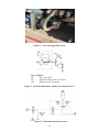
KEY TO HYDRAULICS DIAGRAM (Figure 1)
Key to hydraulics diagram (Figure 1)
A
Anti-swirl device
M
Optional manifold. Where this is fitted means are provided to prevent transfer of
liquid between compartments by adequate foot valves, faucet valves, non-return
valves or interlock mechanisms.
Vft
Compartment foot valve
Vfc
Faucet valve
Fy
Optional additional hose for gravity unmetered delivery.
Fx
Connecting hose to compartments; this is as short as is practicable (jumper hose)
Fp
Filter (pump)
P
Pump
R
Optional valve for pumped unmetered delivery.
Fc
Filter (meter)
Pg
Gas extractor.
Eb
Expansion Box
C
Meter
Vm
Operating valve which may be connected to the pre-setting mechanism of the meter
SA
The above four items Fc, Pg, EB, C, Vm, cl1 and cl2 are usually a complete subassembly of the meter
cl1
Non return valve (pressure assisted)
cl2
Non return valve (point of transfer)
I
Empty hose
13
) The two valves are of the ‘open or closed’ type
) which render any slowing down at the pump intake
) practically impossible
CERTIFICATE HISTORY
ISSUE NO.
UK/0126/0057
DATE
02 July 2009
DESCRIPTION
Type examination certificate first issued.
ILLUSTRATIONS
Figure 1
Figure 2
Figure 3
Figure 4
Figure 5
Figure 6
Figure 7
Figure 8
Figure 9
Figure 10
Figure 11
Hydraulics
General view of system
General view of external cabinet
View showing jumper hose
Amended hydraulics, Authorised Alternative 9.3
Pneumatic interlock system
Amended hydraulics, Authorised Alternative 9.4
Sealing arrangements
Hydraulic diagram, monitored system and key
Examples of closable nozzles
Data Plate
12
Figure 1 Hydraulics
13
Figure 2 General view of typical system
Figure 3 General view of external cabinet showing typical metering system
14
Figure 4 View showing jumper hose
Key to Figure:
R1
Two way valve
Ft.1
Hosereel delivery side of system
Ft.2
Bulk hose side of system
Figure 5 Amended hydraulics, Authorised Alternative 9.3
Figure 6 Pneumatic interlock system
15
Figure 7 Amended hydraulics, Authorised Alternative 9.4
16
(a)
(b)
left
rear
Figure 8 Securing (sealing) arrangements
17
Figure 9 Hydraulic diagram, monitored system and key (below)
18
A
Anti-swirl device
M
Optional manifold. Where this is fitted, means are provided to prevent transfer of
liquid between compartments by adequate foot valves, faucet valves, non-return
valves or interlock mechanisms.
Fy
Optional additional hose for gravity unmetered delivery.
Fx
Connecting hose to compartments; this is as short as is practicable (jumper hose)
Fp
Filter (pump)
P
Pump
R
Optional valve for pumped unmetered delivery.
Fc
Filter (meter)
Pg
Gas extractor.
Eb
Expansion Box
C
Meter
Vm
Operating valve which may be connected to the pre-setting mechanism of the meter
cl1
Non return valve (pressure assisted)
cl2
Non return valve (point of transfer)
SA
The above items Fc, Pg, EB, C, Vm, cl1 and cl2 are usually a complete
subassembly of the meter
Cla
Hose closure, (no anti siphon valve)
I
Empty hose
S1
Sensor 1
S2
Sensor2
Vb
Vacuum breaker
Figure 9 Key
Figure 10 Examples of closable nozzles
Figure 11 Data Plate
Crown Copyright 2009
NATIONAL WEIGHTS AND MEASURES LABORATORY
Department for Business, Innovation and Skills
20