1
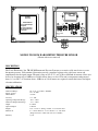
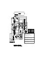
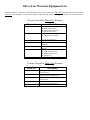
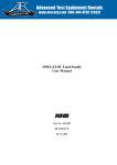
TB-2012M BAROMETRIC PRESSURE SENSOR
USER’S MANUAL
TEXAS ELECTRONICS, INC.
5529 Redfield St. Dallas, TX 75235
Phone (214) 631-2490
P.O. Box 7225 Dallas, TX 75209
Fax (214) 631-4218
Toll Free (800) 424-5651
MICRO
SWITCH
USA
U1
Texas Electronics, Inc.
P1
P2
5529 Redfield St.
Dallas, Tx 75235
C3
D3
TB1
Remove cover of TB-2012M and adjust
D2
for local pressure.
R21
D4
Refer to Pressure vs Voltage/Current
D1
Table under the Barometer section of
+12V
COM.
SIG.
COM.
the service manual.
C99
C1
Model TB-2012M Barometer
R3
R4
R2
R1
R18
R19
R20
C98
R13
R14
R16
R22
REF
C5
C7
R17
C6
ELECTRIC BAROMETER
MODEL NO. TB-2012M
S/N 102795
C4
U2
R11
R12
R8
R9
SPAN
C2
U3
R15
NULL
MODEL TB-2012M BAROMETRIC PRESSURE SENSOR
(Shown with cover removed)
DESCRIPTION
The Texas Electronics, Inc. TB-2012M Barometric Pressure Sensor uses an active solid-state device to sense
barometric pressure. Self-contained electronics provide a regulated voltage to the solid-state sensor and
amplification for the signal output. The unit's range of 26" to 32" or 878 mb to 1080 mb of mercury allows it to
be used at elevations up to 1800 feet or 548.64 meters above sea level. The unit is temperature compensated
from -18° to +50°C. if elevations above 1800 feet or 548.64 meters are required, contact the factory for higher
elevation calibration.
SPECIFICATIONS
Calibration Range:
Supply Voltage:
Current Draw:
Accuracy:
Operating Temperature Range:
Calibrated Temperature Range:
Output:
Optional Output:
Weight:
Dimensions:
26" to 32" or 878 mb to 1080 mb
12 to 15 VDC
<15 mA
+/- 1.3mb
-40° to +50°C
-18° to +50°C
0-1 VDC
4-20 mA
2 lb. or 8.9 N or .907 kg. w/ 60 ft. or 18.3 meters cable
6" or 15.24 cm H x 5" or 12.7 cm W x 3" or 7.62 cm D
(Single enclosure: double enclosure also available)
Warranty:
3 year
FEATURES & BENEFITS
•
•
•
•
•
•
•
Interfaces to virtually all data acquisition systems
Can be used up to 1800 ft. elevation without factory modification
Over 1800 ft. elevation applications available
Easy installation and maintenance
Over 5 years in production
Weatherproof Nema Enclosure for superior outdoor protection
Wide range of 26" to 32" Hg. or 878 to 1080 mb
INSTALLATION & MAINTENANCE
Select a site where the instrument will not be subject to rapid fluctuations of temperature or to jarring and
continuous vibration. Avoid exposing the instrument to direct sunlight or radiant heaters and to direct drafts
such as open windows and doors. A mounting bracket with hardware is attached to the Nema enclosure of the
sensor.
ORDERING INFORMATION
Model #
Description
TB-2012M
TB-2012MA
Barometric Pressure Sensor
Barometric Pressure Sensor, 4-20 mA
Optional Parts / Accessories
Cable
High Elevation:
Additional Cable
Applications of higher than 1800 ft. or 548.64 meters above sea-level require factory
modification.
PROPER EXPOSURE OF METEOROLOGICAL INSTRUMENTS
Generally recognized guidelines follow which depict "ideal" sensor mounting locations. These guidelines or
"rules of thumb" are only suggestive in nature in an attempt to aid the user to selecting optimum representative
sampling locations for a particular sensor.
Reference was made to US Weather Bureau Installation criteria in preparing this data (See Reference 1).
WIND EQUIPMENT:
So far as available sites permit, wind sensors should be placed above the ground on a freely-exposed tower (20
feet or higher) and over terrain that is relatively level and free from obstructions to wind flow. When a
compromise must be made, sensing units should be exposed at least 12 feet above any obstruction within 100
feet and at least as high as any obstruction within 100 to 200 feet of the wind equipment. Support towers or
masts should not be of such bulk or shape as to create an appreciable obstruction to wind flow. Avoid sites
where local obstructions may create up-or-down drafts, eddy currents or jet-flow effects. When sensors are
roof-mounted, they should be installed at least 10 feet (or greater) from the roof surface depending upon the
particular installation site. Turbulence and other local effects can be reduced somewhat by mounting sensors on
the upwind and of the building (that end of the building exposed to the most common local prevailing winds).
Horizontal-mount booms which extend from existing towers should be fabricated so that sensors will extend a
distance of 5 to 10 feet from the tower assembly (dependent on tower thickness).
Wind direction sensors are oriented upon installation in reference to either true north or magnetic north. True
north is obtained by applying a local magnetic variation correction factor to a magnetic north compass
indication (magnetic variation for a particular locality is obtainable from the nearest Weather Bureau Branch
Office). Indicator readings for a true north sensor orientation will then be in terms of true geographic compass
points. All U.S. Weather Bureau surface wind data used for observational network reporting purposes and
general public use is given in reference to this true north format. Indicator readings for a magnetic north sensor
orientation will be in terms of actual readings as would be obtained from directly viewing a magnetic compass
instrument. Wind direction data at Federal Aviation Agency and other aircraft reporting facilities (for direct
control tower-to-pilot utilization) is always made in reference to this magnetic north format.
REMOTE TEMPERATURE/HUMIDITY SENSORS AND INSTRUMENT SHELTERS:
Whenever possible, instrument shelters* as well as remote temperature and/or humidity sensors should be
installed at a height of 4 feet (or greater) over earth or sod at least 100 feet from any concrete or other hardsurfaced area and not closer to any other object than four times the height of the object above the instrument
shelter or remote sensors. Avoid roof installations if possible. If it is necessary to roof-mount shelters and
sensors, they should not be closer than 30 feet to any large, vertical reflecting surface (walls, etc.), exhaust fans,
or cooling towers. Electronic remote sensors when roof-mounted should be at least 9 feet (or greater) above the
roof surface. To minimize radiation effects from the roof, they can also be mounted on a horizontal boom so
that they will extend from the side of a building roof or existing tower. Horizontal booms should extend
approximately 5 to 10 feet from the side of the building roof or tower assembly.
PRECIPITATION GAUGES:
Rain gauges should be installed on a level plot of ground, at a distance from any object of at least two and
preferably four times the height of the object above the top of the gauge. All types of gauges must be exposed
with the rim of the receiver in a horizontal plane and at a level well above the average level of snow surfaces.
*
Standard U.S. Weather Bureau cotton-region shelter (Spec. No. 450.0615, Rev. 8/67)
Roof-mounting of rain gauges should be avoided when possible. Air currents at heights other than at ground
level have been observed to cause an apparent decrease in rainfall catch commensurate with the increase in
mounting height above ground level.
Objects which individually or in small groups constitute a "windbreak" reduce prevailing wind speed in the
vicinity of the gauge. This reduction of wind speed will, as a consequence, also reduce possible eddy currents
and turbulence around the gauge. The presence of such objects is usually beneficial in providing a more
accurate rainfall catch. Ideally, the "windbreak" objects (fences, bushes, etc.) should be generally uniform in
height and distance from the gauge. Height above the gauge should not exceed about twice their distance from
the gauge.
ANEROID BAROMETERS - SELF-CONTAINED MECHANICAL INSTRUMENTS AND
ELECTRONIC REMOTE BAROMETRIC PRESSURE SENSORS:
Select a site where the instrument will not be subject to rapid fluctuations of temperature or to jarring and
continuous vibration. Avoid exposing the instrument to direct sunlight or radiant heaters and to direct drafts
such as open windows and doors.
Reference 1:
U.S. Department of Commerce - National Weather Service Bulletin
LS 5927 Revised, 0-4.12, January, 1963.
SOLAR RADIATION SENSORS:
The Solar Radiation Sensor is normally mounted on a level surface totally remote from trees, poles, or power
lines that might cast a shadow on the sensor at any time of the day. However, there may be occasions, because
of extreme latitudes, when it is desired to mount the sensor at some angle other than level.
The sensors may also be mounted on a sun tracking mechanism or behind a shadow band if diffuse sky
radiation is to be measured.
TB-2012M ALTITUDE SETTING INSTRUCTIONS
To set barometer to your elevation, follow the instructions listed below:
Output:
Range:
0-1V
26 to 32”
.1666V/Inch
.001666V/.01 Inch
Obtain local barometric pressure from NOAA, NWS, airport, radio/TV station, or from any facility that would
have the most accurate information closest to your installation.
If you are using the Texas Electronics, Inc. digital or analog indicators, remove the four cover screws from the
TB-2012M and adjust the null pot (R15) until your indicators agree with the reference obtained. You may want
to do this more than once, especially if the weather is unsettled at the time.
If you are connected to a Solus® Data logger you can set to your elevation by inserting either a plus or
minus voltage in the [calibrate] Offset : xxxx box.
With Solus running follow these steps: from menu bar, click on setup, sensor, edit, select TB-2012M then
insert value desired then save, .10 increases reading by .10”
-.10 decreases reading by .10”
By using the chart below and the following conversion, it is very easy to set up.
Example:
If the pressure reading that you obtained is 29.13”:
From the chart below:
Choose 29, which is .500 V.
Then multiply, 13 x .00166 V. = .0216 V.
.5 V. + .0216 V. = .52160 V. should be the proper output.
Set null pot (R15) until that voltage output is obtained.
26”
27”
28”
29”
30”
31”
32”
=
=
=
=
=
=
=
.00 V.
.166V.
.333V.
.500V.
.666V.
.833V.
1.000V.
NOTICE!
IF THE FINAL OUTPUT FROM THE
OVERALL SYSTEM IS OTHER
THAN 0-1 VOLT, THERE WILL BE
A PA-03-1 AMPLIFIER INSTALLED
IN THE ELECTRONICS PACKAGE
SUCH AS THE BPC-250 OR BPC-500.
THE OUTPUT FROM THE TB-2012M
IS FED DIRECTLY INTO THE PA03-1 AND AMPLIFIED TO THE
USERS NEEDS.
BE SURE TO TAKE THIS INTO
CONSIDERATION WHEN SETTING
UP THE SYSTEM AT IT’S
PERMANENT ELEVATION.
Replace cover and secure evenly. System should not need further calibration or setup.
Altitude ( feet)
R14
25 00 - 9500
44 .2k
95 00 - 13500 61 .9k
13 500 - 1550 0 75 .0k
17 500 - 2050 0 1 1 0 K ( R 1 5 = 5 0 K)
Ma x imu m Altitude is 20500 Fe et
Standard Output Is 0-1 Volt (166Mv./In.)
Altitud e: 0 -250 0 Fe et
Ra nge : 26 " to 32" Hg
Fo r Altitu d e ab ove 25 0 0 feet
Se e Ch art Abo ve
For 0-2.5 Volt Output
R14=50K R15=5K R16=95.5K R17=50K
P OT
P OT
For 0-3 Volt Output
R14=50K R15=20K R16=120K R17=10K
P OT
P OT
For 0-5 Volt Output
R14=64.9K R15=20K R16=191K R17=50K
P OT
P OT
Warranty
Texas Electronics, Inc. (hereafter TEI) warrants the equipment manufactured by it
to be free from defects in material and workmanship. Upon return, transportation
charges prepaid to TEI, within three (3) years of original shipment of sensors and
one (1) year of original shipment of electronics, recorders and indicators, TEI will
repair or replace, at its option, any equipment which it determines to contain
defective material or workmanship, and will return said equipment to purchaser,
F.O.B., TEI. Texas Electronics shall not be obligated however to repair or replace
equipment which has been repaired by others, abused, improperly installed,
altered or otherwise misused or damaged in any way. TEI will not be responsible
for any dismantling, re-assembly, or reinstallation charges.
This warranty is in lieu of all other warranties, expressed or implied. TEI shall
not be liable for any special, indirect, incidental or consequential damages
claimed in connection with any rescission of this agreement by purchaser.
For a list of specific items covered by the extended warranty, see the Three-Year
Warranty Equipment List.
Three-Year Warranty Equipment List
Effective February 1, 1992 all of Texas Electronics, Inc. sensors will carry a Three-Year warranty instead of the previous
One-Year. The remainder of terms and conditions of the warranty remains unchanged. A specific list of items follows.
Sensors Covered by Three-Year Warranty
Parameter
Wind Direction
Wind Speed
Barometric Pressure
Relative Humidity
Rainfall
Temperature
Solar Radiation
Model No.
TD-105 (Synchro)
TD-104D (Potentiometer)
TD-110-L2 (Photo-Chopper)
TD-106 (Potentiometer)
TV-110-L2 (Photo-Chopper)
TV-110-L3 (Photo-Chopper)
TV-114 (A.C. Generator)
TB-2012
TH-2013
TH-2013V
TR-525
TR-6118
TT-101 (Outdoor)
TT-103R (Surface Mount)
TT-103R-W (Water Probe)
TT-309I (Indoor)
TS-100
Systems Covered by Three-Year Warranty
Model No.
WSC-5-S
WSC-5-ST
WSC-5-D
WSC-5-DT
WDC-2
Description
Wind Speed Controller
Single Set Point
Wind Speed Controller
Single Set Point with Time Delay
Wind Speed Controller
Dual Set Point
Wind Speed Controller
Dual Set Point with Time Delay
Wind Direction Controller