1
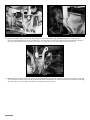
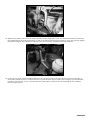
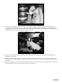
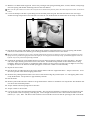
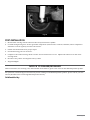
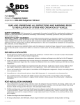
491 W. Garfield Ave., Coldwater, MI 49036
Phone: 517-279-2135
Web/live chat: www.bds-suspension.com
E-mail: [email protected]
Part#: 014850
Product: 8.5" Long Arm Suspension System
Application: 1987-2001 Jeep Cherokee XJ (4.0L 16./auto trans.)
Read and understand all instructions and warnings prior
to installation of system and operation of vehicle.
SAFETY WARNING
BDS Suspension Co. recommends this system be installed by a professional technician.
In addition to these instructions, professional knowledge of disassembly/ reassembly procedures and post installation
checks must be known.
PRODUCT SAFETY WARNING
Certain BDS Suspension products are intended to improve off-road performance. Modifying your vehicle for off-road use may result in the vehicle handling differently than a factory equipped
vehicle. Extreme care must be used to prevent loss of control or vehicle rollover. Failure to drive your modified vehicle
safely may result in serious injury or death. BDS Suspension Co. does not recommend the combined use of suspension
lifts, body lifts, or other lifting devices.
You should never operate your modified vehicle under the influence of alcohol or drugs. Always drive your modified vehicle at reduced speeds to ensure your ability to control your vehicle under all driving conditions. Always wear your seat
belt.
Pre-Installation Notes
1.
Special literature required: OE Service Manual for model/year of vehicle. Refer to manual for proper disassembly/
reassembly procedures of OE and related components.
2.
Adhere to recommendations when replacement fasteners, retainers and keepers are called out in the OE manual.
3.
Larger rim and tire combinations may increase leverage on suspension, steering, and related components. When
selecting combinations larger than OE, consider the additional stress you could be inducing on the OE and related
components.
4.
Post suspension system vehicles may experience drive line vibrations. Angles may require tuning, slider on shaft
may require replacement, shafts may need to be lengthened or trued, and U-joints may need to be replaced.
5.
Secure and properly block vehicle prior to installation of BDS Suspension components. Always wear safety glasses
when using power tools.
6.
If installation is to be performed without a hoist, BDS Suspension Co. recommends rear alterations first.
7.
Due to payload options and initial ride height variances, the amount of lift is a base figure. Final ride height
dimensions may vary in accordance to original vehicle attitude. Always measure the attitude prior to beginning
installation.
POST-INSTALLATION WARNINGS
1.
Check all fasteners for proper torque. Check to ensure for adequate clearance between all rotating, mobile, fixed, and
heated members. Verify clearance between exhaust and brake lines, fuel lines, fuel tank, floor boards and wiring
harness. Check steering gear for clearance. Test and inspect brake system.
2.
Perform steering sweep to ensure front brake hoses have adequate slack and do not contact any rotating, mobile
or heated members. Inspect rear brake hoses at full extension for adequate slack. Failure to perform hose check/
replacement may result in component failure. Longer replacement hoses, if needed can be purchased from a local
parts supplier.
3.
Perform head light check and adjustment.
4.
Re-torque all fasteners after 500 miles. Always inspect fasteners and components during routine servicing.
rev. 5/2/2013
014850 Page 1
PARTS LIST
440
FRONT
*Qty in ( ) for 124654 only
Part #
034852
084601R
01370
715
Qty* Description
2
1
1
1
2
2
4
2
2
2
4
2
2
6
16
2
2
2
2
2
01371
01372
01377
01378
22
01373
01374
36270
01375
01383
2
1
1
1
1
1
1
2
2
2
2
2
2
01468
(2)
36274
2
3523RB
8(4)
61
4(2)
60107
6
A161
1
01398
1
M02888RB 2
51792
1
516
1
Page 2 014850
Coil Springs
Pitman Arm
Long Arm Crossmember
Bolt Pack
9/16"-12 x 4-1/2" bolt
9/16"-12 prevailing torque nut
9/16" SAE flat washer
7/16" SAE flat washer
7/16"-14 x 3-1/2" bolt
10mm-1.50 x 80mm bolt
10mm-1.50 x 40mm bolt
10mm-1.50 x 30mm bolt
10mm-1.50 prevailing torque nut
3/8" heavy-duty oversized flat
washer
3/8" USS flat washer
3/8"-16 x 1-1/2" self-tapping bolt
7/16"-14 x 4-1/2" bolt
7/16" prevailing torque nut
7/16"-14 x 1-1/4" bolt
#12 x 3/4" self-drilling hex head
screw
Wire Clamp
Mountable nylon cable tie
1/8" x 1-1/4" cotter pin
Side Support Plate (drv)
Side Support Plate (pass)
Nut Tab (drv)
Nut Tab (pass)
Crush Sleeve
Upper Control Arm
Upper Control Arm End (assembled)
1" Jam Nut
Lower Control Arm
Lower Control Arm Flex End
(assembled)
Lower Control Arm End
1-1/4" Jam Nut
Lower Control Arm Bushing
0.875 x 0.156 x 2.620
Grease Zerk
Front Track Bar Assembly
Track Bar Bracket
Track Bar Bushing
Track Bar Sleeve
Grease Fitting
1
1
1
4
1
1
01360
2
01361
2
01354
1
3396
2
438
1
A100
2
01302
2
45313
2
01325
2
1
718
2
4
2
2
2
4
2
2
2
2
2
3529
2
3528
2
22510
2
5188
2
B06103C
2
CCW-03-050 4
099000
3
Bolt Pack - Track Bar
1/2"-13 x 2-1/2" bolt
1/2"-13 prevailing torque nut
1/2" SAE flat washer
12mm-1.75 x 80mm bolt
12mm-1.75 prevailing torque nut
Sway Bar Link Mount
Sway Bar Link Mount Gusset
Weld-on Stabilizer Bracket
Front Bump Stop Spacer
Bolt Pack - Bump Stops
Sway Bar Link Assembly
Disconnect Stud
0.625 x 0.109 x 1.375 Sleeve
Sway Bar Link Bracket
Bolt Pack
1/2-20 prevailing torque nut
1/2" SAE flat washer
1/2"-20 jam nut
3/8"-16 x 2-1/2" bolt
3/8"-16 prevailing torque nut
3/8" SAE flat washer
7/16"-14 x 1-1/2" bolt
7/16"-14 prevailing torque nu
7/16" SAE flat washer
7/16" USS flat washer
#10-16 x 5/8" self-drilling screw
Bump Stop (1987-1996 Only)
Bump Stop (1997-2001 Only)
Front Brake Line
Brake Line Clip
Brake Line L Bracket
Crush Washer
Zip Tie
REAR
Part #
22512
5188
099000
01312
01475
P00932
B561G2
2KB-W96
51
52
M02402RB
M02403RB
3533RB
516
Qty
1
1
1
2
2
2
2
2
2
4
4
4
4
2
4
Description
Rear Brake Line
Brake Line Clip
Zip Tie
XJ Rear Shackle
Rear Shock Mount
Shock Stud Kit
5/16" x 1" Self-Tapping Bolt
2" Tapered Block
0.750 x 0.095 x 3.140 Sleeve
0.750 x 0.095 x 2.750 Sleeve
XJ Spring Bushing (small eye)
XJ Spring Bushing (large eye)
XJ Shackle Bushing
Straight Grease Zerk
U-bolts, High Nuts and Washers
Glossary of Terms
OE
: Original Equipment
SAE washer : Small OD, tight fit to bolt of same size
USS washer : Larger OD then SAE, loose fit on bolt of same size
ft-lbs
: Foot Pounds - standard torque units
INSTALLATION INSTRUCTIONS
Note: This suspension system is design for use with 4.0 L 6 cylinder engine/automatic transmission equipped vehicles only. With this
setup the transmission crossmembers will be positioned approximately 14” from the back of the OE lower control arm pocket. This
dimension can be checked to ensure the proper fitment of this suspension system on your vehicle.
014850 Page 3
Front Installation
1.
Measure and record the distance from the center of the wheel to the bottom of the fender opening:
2.
Park the vehicle on a clean, level surface and block the rear wheels for safety.
3.
Safely raise the front of the vehicle and support with jack stands under the frame rails.
4.
Remove the front wheels.
5.
Locate the plastic retaining clip on the inside of the driver’s side uni-body frame rail (Fig 1). This clip will be holding
4 lines/hoses. Remove the lines/hoses from the clip and remove the clip from the body.
LF ______ RF_______ RR _______ LR ________
Fig. 1
6.
The two steel lines (fuel and brake) will be reattached with the provided clips and self-drilling screws. Disconnecting
the front drive shaft from the differential will make this easier but is not necessary. The remaining plastic lines will
be fastened to the new crossmember after it is installed.
7.
Locate the hole in the frame where the original plastic retaining clip was installed. Install the brake hard line to the
frame with the provided clip and self-drilling screw just ahead (1/2” max) of the existing hole in the frame (Fig 2).
Position the line up against the floor with the clip mounting tab pointing down. Carefully reform the brake line as
needed. Tighten screw securely.
8.
Attach the fuel line in the same manner as the brake line. Position the clip directly below the brake line clip with
the mounting tab pointing up (Fig 2). This will make the fuel line run low, close to the uni-body pinch weld.
Note: These line locations provide clearance for the new upper control arm mounting bolt.
Fig. 2
Page 4 014850
9.
Remove the four transmission mount nuts from the transmission crossmember (Fig 3). Retain hardware.
Fig. 3
10. With a hydraulic jack, lift the transfer case/transmission assembly just enough to relieve pressure from the transmission crossmember.
11. Remove the nuts/bolts retaining the crossmember to the frame and remove the crossmember from the vehicle (Fig 4).
Note: If equipped with a factory installed transfer case skid plate, remove that as well (Fig 5). It will not be reused.
Fig. 4
Fig. 5
12. Some models may use a combination of threaded studs/nuts and bolts to fasten the OE crossmember (Fig 4). If this
is the case, the threaded studs must be removed. The studs can be removed by either clamping vise grips on it,
using the double nut method or tack welding a nut to the stud and using a wrench to remove it.
13. Locate the third threaded hole in the uni-body rails just ahead of the two that were used to mount the OE
crossmember (Fig 4). Ensure that the threads are clean of dirt and rust (10mm-1.5). These holes will be used to
mount the new crossmember in conjunction with the original two holes (per side).
14. With the help of an assistant, place the crossmember (01370) up to the uni-body and align the front threaded hole
in the body with the front mounting hole in the crossmember. Loosely attach the crossmember to the frame with a
10mm x 30mm bolt and 3/8” USS washer (BP 715) in the second hole from the front of the crossmember on each side
of the vehicle (Fig 6).
Note: Make sure that the remaining loose plastic lines on the driver’s side are to the inside of the upper control arm mount on the new
crossmember.
014850 Page 5
Fig. 6
15. Thread a 10mm x 40mm bolt and 3/8” oversized washer (BP 715) in the front hole on each side of the crossmember
just a couple of turns to help square it to the frame and snug the 10mm x 30mm bolt so the crossmember is setting
tight to the bottom of the frame. Remove the front 10mm x 40mm bolt and washer.
16. Locate the provided crossmember side support plates (01371, 01372). These parts are driver’s and passenger’s
side specific. Identify the correct side by matching the large relieve in the brackets to the existing bolt holding the
crossmember. The relief in the bracket will clear the bolt head.
17. Attach the side support plate so that they “sandwich” the crossmember between themselves and the frame (Fig 7).
Attach the brackets with 10mm x 40mm bolts and 3/8” oversized washers (BP 715) in the forward-most and
rearward-most holes in the side plates/crossmember. Ensure that the side plates are flush against the side of the
frame and snug hardware.
Fig. 7
18. With the side plates in position, mark the center of the two side mounting holes to be drilled. The rear hole is larger
than the front hole.
19. With the side support mounting holes marked, remove the two outer 10mm bolts and remove the side supports from
the vehicle.
20. Drill a 7/16” hole at the front mark for the side plate. Only drill through the first layer of the frame. Do not drill all
the way through the frame.
21. Drill a 7/16” hole at the rear mark for the side plate. Drill outside and inside layers of the frame. Drill straight in
the frame as square as possible to the bottom surface of the frame.
CAUTION: BE CERTAIN that all the fuel lines, brake lines, etc are clear from the area being drilled.
Page 6 014850
22. With the rear thru-hole drilled to 7/16”, go back with a 5/8” drill (or a uni-bit works well too) and drill just the
outside layer of the frame. You will now have a 7/16” and a 5/8” hole in the outside of the frame and a single 7/16”
hole on the inside (Fig 8).
Fig. 8
23. Install the side supports back into position with the same hardware as before. Lightly snug the hardware. Install
the provided nut tab (01377, 01378) in the slotted hole in the frame in front of the side support (Fig 9), back to the
7/16” hole drilled earlier (the nut tabs are driver’s and passenger’s side specific to match the angle of the slot).
Loosely fasten the side support with a 7/16” x 1-1/4” bolt and 3/8” USS washer (BP 715) into the nut tab.
Note: Holding the nut tab with vise grip pliers eases installation.
Fig. 9
24. Insert the provided 5/8” x 3-5/8” frame crush sleeve (22‑1) in the 5/8” hole just drilled in the frame (Fig 10). Do not
push it all the way in at this time.
014850 Page 7
Fig. 10
25. Install a 3/8” USS washer on a 7/16” x 4-1/2” bolt (BP 715) and insert it into the frame crush sleeve. Push the bolt
and sleeve all the way into the frame so that the sleeve is against the inside surface of the frame and the bolt is
sticking out of the inside 7/16” hole. Fasten the bolt on the inside of the frame with a 3/8” USS washer and 7/16”
nut from bolt pack 715 (Fig 11). Leave hardware loose. Ensure that the bolt does not hit the fuel or brake lines.
Reform these lines as necessary.
Fig. 11
26. Locate the second hole from the rear of the crossmember (Fig 12 - on both sides). Using the crossmember hole as a
guide mark and drill the hole to 5/16”.
Page 8 014850
Fig. 12
27. Apply Loctite® to the threads of a 3/8” x 1-1/2” self-tapping bolt and 3/8” oversized washer (BP 715) and install in
each of the drilled holes in the bottom of the frame (one on each side). Torque bolt to 30 ft-lbs.
28. Remove each of the 10mm bolts one at a time and apply Loctite® to the threads. Reinstall the bolts and torque to 40
ft-lbs.
29. With all of the main crossmember bolts tight, go back and torque the four 7/16” side plate bolts to 50 ft-lbs.
30. Lower the transmission mount onto the crossmember by aligning the studs in the slots. Fasten the mount to the
crossmember with the OE nuts and torque to 25 ft-lbs.
31. Go back and check the clearance of all the lines running down the driver’s side of the frame. Attach the plastic
lines to the crossmember with the mount style wire tie (BP 715) by pushing the wire tie into the ¼” hole in the upper
control arm mount and securing the lines (Fig 13).
Fig. 13
32. Support the front axle with a hydraulic jack.
33. Remove shocks, retain lower shock hardware.
34. Remove OE sway bar end links and discard (Fig 14).
014850 Page 9
Fig. 14
35. Disconnect the steering stabilizer from the axle and retain hardware. If replacing, remove the steering stabilizer
from the drag link by removing the nut and dislodging the tapered stud with a pickle fork (Fig 15).
Fig. 15
36. Disconnect the track bar from the axle (Fig 16). Disconnect the OE track bar frame bracket from the driver's side.
Remove the four bolts/nuts and remove the bracket and track bar from the vehicle. Save the frame mount hardware.
Fig. 16
Page 10 014850
37. Disconnect drag link from pitman arm (retain hardware). Use a pickle fork to dislodge the drag link from the
pitman arm.
38. Mark the relationship between the pitman arm and the steering box sector shaft. Remove the pitman arm mounting
nut and washer. Retain hardware.
39. Using the appropriate pitman arm puller, remove the OE pitman arm and install the new provided drop pitman arm
(084601R) using the alignment marks to ensure it is indexed properly. Fasten with the OE nut and washer and
torque to 185 ft-lbs.
40. Remove brake line retaining clips.
41. Remove fasteners holding brake line anchors to frame on driver’s and passenger’s side.
42. Disconnect passenger’s side rubber brake line from metal hard line.
43. Disconnect brake line from caliper and discard crush washers, retain the OE banjo bolt. Ensure old washer is
removed from caliper and brake line mounting area.
44. Install new upper brakeline bracket (B06103C) with OE bolt.
45. Mount hard line into new bracket before installing new stainless steel line.
46. Install BDS front brake line (22510) by attaching upper portion first. Tighten securely (Fig 17).
Fig. 17
47. Install lower portion with provided new crush washers and original banjo bolt.
Note: One washer is required on EACH side of the fitting. Brake line must face up after installation. Torque bolt to 20 ft lbs (Fig 18).
Fig. 18
014850 Page 11
48. Repeat brake line installation for driver’s side.
49. If equipped, remove the lower coil spring retainer clips from the axle (Fig 19). Retain clips and bolts.
Fig. 19
50. Lower the front axle and remove the front coil springs from the vehicle.
51. Grease and install the provided bushings (3523RB) and sleeves (61-1) in the lower control arm (01375) and
adjustable lower control arm ends (01468).
Note: If using flex end style lower control arms follow same instructions as the standard ends. The flex ends came pre-assembled.
52. Install the provided 90 degree grease fittings (60107) in the lower control arms and control arm ends.
53. Thread the provided jam nut, followed by the adjustable end onto the lower control arm. Adjust the length of the
control arm so that it is 32-3/4” from center of eye to center of eye.
54. Thread the provided jam nut, followed by the provided assembled flex end (01374) onto the upper control arm
(01373). Install the provided grease fittings in the flex ends (Fig 20). Adjust the length of the control arm so that it
is 28-3/8” from center of eye to center of clevis (Slide bolt through clevis end to get this measurement).
Fig. 20
55. Install the adjustable end of the lower control arms into the new lower control arm pockets in the crossmember (Fig
21). Loosely fasten the arms with 9/16” x 4-1/2” bolts, nuts and 9/16” SAE washers (BP 715).
Note: Apply a small amount of grease to the faces of the bushings to aid in installation of the control arms.
Page 12 014850
Fig. 21
56. Loosen but do not remove all the OE upper and lower control arm mounting bolts.
57. With the front axle properly supported, remove the lower control arms from the frame and the axle. Retain the axle
mount hardware.
58. Install the new lower control arms in the axle mounts and loosely fasten with the OE hardware.
59. Install the new upper control arms into the new upper control arm pockets in the crossmember (Fig 22). Fasten
the arms with 7/16” x 3-1/2” bolts and 7/16” SAE washers (BP 715) into the welded nut on the crossmember. Use
Loctite® on the bolt threads.
Note: In some cases it may be necessary to loosen the exhaust to gain clearance for installing the passenger’s side control arm bolt. Torque the 7/16” bolts to 50 ft-lbs.
Fig. 22
60. Attach the clevis end of the upper control arms to the front axle mounts (Fig 23). The clevis end will angle in toward
the center of the vehicle. Fasten the arms to the axle with 10mm x 80mm bolts, nuts and 3/8” SAE washers (BP
715). Leave hardware loose.
014850 Page 13
Fig. 23
61. Using a provided zip tie, attach the differential breather tube to the driver’s side upper control arm.
62. Locate and drill a 5/16” hole in the center of the front coil spring axle mounts (Fig 24). Use a provided 3/8” selftapping bolt (#438) to cut the threads for the bump stop extension (3396). Remove the bolt.
Fig. 24
63. Remove the front OE rubber bump stops and replace with the provided longer ones (3528 or 3529). Apply a small
amount of grease to the bump stop and push it into the mounting cup.
64. The front sway bar link axle mounts must be cut off to make room for the extended mounts provided. These new
mounts will provide proper steering linkage clearance once the vehicle is lifted. Starting on the driver’s side, make a
cut mark on the axle link mount that is flush with the top surface of the axle coil mount. This mark will be approximately 2-5/8” from the top point of the link mount (Fig 25A, B).
Page 14 014850
Fig. 25B
Fig. 25A
65. Cut the link mount along the cut line with a reciprocating saw or cut off wheel. Take care to make the cut as straight
and square as possible. The top portion that is cut from the driver’s side mount will be used as a template for the
passenger’s side. Also, making a square cut here will help with setting up the welding process later on.
66. With the driver’s side link mount removed, use the cut portion as a template by aligning the hole and the profile of
the cut piece with the passenger’s side mount. Mark the cut line on the passenger’s mount (Fig 26). Note: A ½” bolt
can be inserted in the mounting holes of the ends to aid in aligning them.
Fig. 26
67. Cut the passenger’s side link on the cut line in the same fashion as the driver’s side.
68. With the link mounts cut, go through and remove any corrosion, oil, etc from the remaining portion of the OE link
mounts as well as on the top of the OE stabilizer mounting bracket (pass. side). The surfaces must be corrosion/oil
free to promote quality welds.
Important Installation Note: A certified welder should perform all welding operations. This step can be skipped until the vehicle is
complete and can be carefully driven to a local welding shop if need be. Always keep a fire extinguisher near by when welding. Disconnect both the positive and negative battery cables before welding.
69. Position a provided new link mount (01360) on the cut surface of the original driver’s side mount. The front edge of
the new mount should be flush with the front cut edge of the old mount. The inside surface of the link mount should
also be flush/parallel with the inside surface of the original mount. Tack weld the new link mount in place (Fig 27A,
B). Double check to see that the new mount is square with the original. Note: It is recommended to grind a bevel in
the edge of the new link mount (outside where it meets the original mount) to promote good weld penetration of both
pieces of material.
014850 Page 15
Fig. 27A
Fig. 27B
70. Repeat the link setup procedure on the passenger’s side of the vehicle (Fig 28). With both pieces tacked in place
check the relationship between the two mounts to see that they are the same. Measure the inside distance between
the tops of the links and the bottoms of the links to see that they are the same (approximately 38-1/2”).
Fig. 28
71. With the links positioned correctly, locate the provided formed side gussets (01361). Position the gussets so that they
are parallel to the front surface of the original link mount and flush to the outside surface of the new link mount (Fig
29). Once they are in the desired position, tack weld the gussets in place.
Page 16 014850
Fig. 29
72. With the link mount parts correctly in place finish weld the components to the axle. Weld all around the point where
the original mount meets the new mounts as well as the full length of the gusset where it meets the new and original
link mounts (Fig 30). Note: Weld the back side of the gusset for best weld penetration and aesthetics.
Fig. 30
73. Locate the top of the original stabilizer mount on the passenger’s side of the axle. Measure from the front edge of
the bracket toward the rear ¾” and mark on the top of the bracket (Fig 31). Make a line along the top of the bracket,
parallel to the front face at the ¾” marked distance. This will be a reference line for installing the new stabilizer
mount/support gusset.
014850 Page 17
3/4"
Fig. 31
74. Position the new provided stabilizer mount (01354) on the top of the original mount so that the hole is to the driver’s
side and the front surface is aligned to the line marked on the top of the OE bracket (Fig 32). The will butt up to the
passenger’s side link mount that was just installed.
Fig. 32
75. Check that the stabilizer mount is perpendicular to the top of the OE mount and position against the link mount
and tack weld in place. Double check the position and finish weld the mount to the OE bracket and the link mount.
76. With all welding complete allow the brackets to cool and then paint any raw metal to prevent corrosion.
77. When the paint is dry on the new link mounts, install the new BDS coils (034852) with the provided lower bump
stop (3396) inside the spring. Rotate the spring until the end is seated correctly in the axle mount.
78. If equipped, install the OE coil retainer clips with the original bolts. Torque to 25 ft-lbs.
79. Attach the bump stop extension with the provided 3/8” x 3-1/2” bolt and 3/8” USS washer (BP #438). Torque to
approximately 30 ft-lbs.
80. Install the new BDS shocks in the vehicle with the provided upper stem bushings/washers/nuts. Attach the shock
to the axle with the OE hardware. Torque upper nut until the bushings begin to swell and install the jam nut.
Torque the lower OE hardware to 25 ft-lbs.
81. Install the provided disconnect ball studs (01302) in the mounts so that the ball portion points toward the center
of the vehicle (Fig 33). Install the stud with a ½” lock nut and two ½” SAE washers (BP 718), one on each side of the
mount. Torque stud to 60 ft-lbs.
Page 18 014850
Fig. 33
82. Install the provided upper u-bracket (01325) to the sway bar using the original link mounting hole with a 7/16”
x 1-1/2” bolt, nut, 7/16” SAE and 7/16” USS washers (BP 718). Install the bolt up through the u-bracket with an
SAE washer into the sway bar. Fasten with the nut and USS washer. Position the bracket so that the thru-holes are
parallel with the stud on the axle (Fig 34). Torque to 50 ft-lbs.
Fig. 34
83. Locate the new provided sway bar disconnect assemblies (A100). Lightly grease and install the provided sleeves
(45313) in the bushings.
84. Attach the sway bar link assembly to the upper u-bracket with the provided 3/8” x 2-1/2” bolt, nut and 3/8” SAE
washers (BP 718), running from the inside out. Torque bolt to 30 ft-lbs. Leave the sway bar links disconnected at
this time.
85. Install the provided new track bar bracket (01398) to the driver's side frame with the original hardware. Torque the
factory hardware to 60 ft-lbs starting with the lower bolts. (Fig 35)
014850 Page 19
Fig. 35
86. Grease and install the provided track bar bushings (M02888RB) and sleeve (51792) in the new track bar assembly
(A161). The exact length will be adjusted at the end of the installation. Install the provided grease fitting (516) in
the adjustable end of the track bar.
87. Install the new track bar assembly to the original steering stabilizer axle mount with a 1/2" x 2-1/2" bolt, nut and
washers (BP 440) so the track bar runs up toward the new frame mount. Leave hardware loose. The frame end will
be attached at the end of the installation.
88. Attach the drag link to the pitman arm with the original castellated nut and new provided cotter pin (BP 715).
Torque nut to 50 ft-lbs. Do not loosen the nut to install the cotter pin, only tighten.
89. Steering Stabilizer Installation:
Using OE cylinder: Attach the loose end of the cylinder to the new stabilizer bracket on the axle with the OE
hardware. Run the bolt from the back forward and torque to 60 ft-lbs.
Installing new cylinder: Install the provided bushings in the new stabilizer cylinder. Install the provided sleeve
(0.625" x 0.060" x 1.375") in the body end of the cylinder. Attach the body end of the stabilizer to the new stabilizer
bracket with the original stabilizer hardware. Run the bolt from the back forward. Torque bolt to 60 ft-lbs. Attach
the opposite end of the cylinder to the drag link with the new provided stud and hardware. Torque stud the large
stud nut to 55 ft-lbs and the small nut to 40 ft-lbs.
90. Use zip ties to fasten brake lines clear of any rotating or heated components.
91. Install wheels.
92. Remove the jack stands and lower the vehicle to the ground.
93. Bounce the front of the vehicle to settle the suspension. Visually check to see that the front axle is centered under
the vehicle. Turn the steering wheel back and forth to help center.
94. Adjust the track bar until the proper length is set so the track bar end will mount into the new frame bracket.
Fasten in the mount with a 12mm x 80mm bolt, nut and 1/2" SAE washers. Torque hardware to 65 ft-lbs.
95. Check that the track bar end is square in the frame mount and lock off the jam nut securely.
96. Torque the track bar axle mount hardware to 65 ft-lbs.
97. Lock off upper and lower control arm jam nuts securely. Ensure the flex ends are square to the pockets before
tightening. Torque the lower control arm bolts to 95 ft-lbs. Torque the upper control arm bolts at the axle to 40
ft-lbs.
98. Ensure the vehicle setting level on the ground. Pull the spring collar up of the disconnect ends and attach them to
the ball studs on the axle. Make sure the disconnect end stud is square with the ball stud and tighten the jam nut
against the disconnect end. These disconnects allow for ½” adjustment (1/2” longer from full-bottomed out).
99. Check the jam nuts to be sure they are securely locked off. Disconnect both end links and fold them up against
the sway bar. Clip the provided lanyard/clip assembly around the sway bar/end link and find the best position for
mounting the lanyard. This position will vary from vehicle to vehicle. Use your best judgment. Use the provided
self-drilling screws to mount the lanyard to the body/frame.
Page 20 014850
100.
With the lanyards installed, reconnect the sway bar links to the axle. The lanyards can be reattached to
themselves so that they remain out of the way of moving parts when not in use.
Front Lower Control Arm Pockets
Note: This suspension system does not require the removal of the OE lower control arm pockets. Under normal driving conditions and
offroad use the new lower control arms will not contact the OE lower control arm pockets. However, heavy impacts (such as jumping)
can potentially cause contact between the arms and the pockets. Also, if the front bump stops are not installed per these instructions,
contact can occur under compression. Use your best judgment on whether the pockets should be removed or not. These pockets are no
longer needed once this install is complete. Some individuals will remove the pockets purely for appearance purposes.
1.
Mark a cut line on the two lower control arm pockets that follow the contour of the frame (Fig 36). Using a reciprocating saw or cut-off wheel remove the pocket from the frame. Take care not to cut into the frame.
2.
Grind the cut edges smooth. Paint all exposed metal to prevent corrosion.
Fig. 36
Rear Installation
1.
Block the front wheels. Safely raise the rear of the vehicle and support with jack stands for safety.
2.
Remove wheels.
3.
Place a floor jack under the rear axle for support and remove the rear shocks. Retain the upper mounting hardware.
Note: The upper shock mount bolts are prone to corrosion. Take care in removing the bolts as they can break easily.
Use plenty of quality penatrating oil on the threads prior to disassembly.
4.
Remove sway bar mounts from the body.
5.
Remove the two bolts mounting the parking brake bracket from the driver's side frame (Fig 37). Allow it to hang
free.
014850 Page 21
Fig. 37
6.
Measure back 3-1/2" from each of the two bracket mounting holes and mark. Drill a 1/4" hole at each mark. This
will be the new mounting location for the bracket. It will be reattached at the end of the installation with the new
provided 5/16" x 1" self-tapping bolts.
7.
Remove retaining clip holding brakeline to driver’s side frame.
8.
Disconnect rubber brake line from hard line at retaining clip location.
9.
Disconnect hardlines from brake line junction block on axle.
10. Unbolt brake line junction block from axle. Retain bolts.
11. Install new BDS rear brake line (22512) in place. Torque to 25 ft-lbs.
12. Reattach axle breather.
13. Install new retaining clip.
14. Locate the factory lower shock mounts on the axle. These must be removed from the axle tube completely to make
room for the new high-clearance shock mounts. Carefully cut the brackets off of the axle tube (Fig 38). Take
care not to cut into the axle tube. Grind axle surface smooth. The new mounts will be installed at the end of the
installation.
Fig. 38
15. Apply a small amount of grease to bushings (3533RB) and install bushings, sleeves (52) and grease zerks into the
new shackles (01312).
16. Grease and install bushings into leaf spring eyes (M02402RB & M02403RB) then install sleeves (52 & 51). Note: The
longer sleeves (51) go in the large spring eye bushings.
Page 22 014850
17. With the rear differential supported, remove the passenger side spring mounting bolts, u-bolts, shackle, and springs.
Save leaf spring and shackle mounting bolts for later installation.
Note: Once all of the u-bolts are removed, the sway bar can be disconnected from the frame and removed from the vehicle. It will not be
reused.
18. Locate the bumper bolt that is protruding into the shackle pocket (Fig 39). This bolt will contact the new larger
shackle through suspension travel. The bolt can either be cut off flush with the welded nut on the body or removed.
Fig. 39
19. Install the new spring and shackle in the OE locations with the original hardware. Leave the spring and shackle
bolts loose at this time. The shackle grease fittings should be toward the front of the vehicle.
Note: The system is designed to be use with a slip yoke eliminator kit and new CV style drive shaft. The shims installed on the leaf
springs are set to provide the appropriate drive line angles for most slip yoke/CV driveshaft setups. If additional/different shims are
required, they can be purchased separately from BDS.
20. Position the provided 2" tapered block between the axle and leaf spring by align the center pins/holes. The short
end of the taper should go toward the front of the vehicle. Install the new provided u-bolts and hardware. Snug
hardware. Notes: Do not torque to specification until vehicle is on the ground. In some cases it might be necessary
to slightly clearance the holes in the OE spring plate to allow the u-bolts to install smoothly.
21. Repeat for driver’s side.
22. Install the new provided shocks to the upper shocks mounts with the original hardware. Torque to 20 ft-lbs. Leave
the lower portion of the shock hanging at this time.
23. Reattach the parking brake bracket to the driver's side frame using the provided 5/16" x 1" self-tapping bolts in the
newly drilled holes. Torque bolts to approximately 15 ft-lbs.
24. Install wheels.
25. Remove jack stands and lower vehicle to the ground. Bounce vehicle to normalize rear suspension. The shackles will
now be in their intended position.
26. Torque shackle and leaf spring bolts to 95 ft-lbs.
27. Torque u-bolts to 75-90 ft-lbs.
28. Locate the new lower shock mount brackets (01475). The new mounts should be positioned on the lower half of the
axle just inside of the leaf spring u-bolt (Fig 40). Leave enough room between the u-bolt and the bracket to weld
(about 1/2" - 3/4"). Note: The driver's side mounts to the back side of the axle and the passenger's side to the front.
014850 Page 23
Fig. 40
29. Position the new shock mounts so the flat shock mount surface is parallel to the centerline of the shock (Fig 41).
This will ensure that the shock bushing will run square in the shock eye at ride height. Tack the brackets into
position.
Fig. 41
30. With the brackets in position go back and fully weld them to the axle tube. Allow the brackets/axle to cool and paint
all exposed metal to prevent corrosion.
31. Install the provided shock stud (P00932) on the bracket with the provided hardware. Torque nut to 55 ft-lbs.
32. Install the shock on the new stud and fasten with the provided hardware (Fig 42). Torque hardware to 40 ft-lbs.
Page 24 014850
Fig. 42
POST-INSTALLATION
1.
Bleed brakes starting with the wheel furthest away from master cylinder.
2.
Go back through and grease all new greasable components (control arms, track bar, shackles). These components
should be serviced regularly and after off-road use.
3.
Double-check all fasteners for proper torque.
4.
Check all moving parts for clearance.
5.
Complete a full radius turning check to ensure that no interference occurs. Adjust front wheel toe-in and center
steering wheel.
6.
Reconnect the positive and negative battery cables.
7.
Align headlights.
Notice to Dealer/Installer
These instructions, the warning card, and included decals must be given to the owner of this BDS Suspension product.
For questions, technical support and warranty issues relating to this BDS Suspension product, please contact your distributor/installer before contacting BDS Suspension directly.
Sold/Installed by:
014850 Page 25