1
SYS
TEM
600
SER
IES
MAC
3130 N. MITTHOEFFER ROAD
P.O. BOX 36550
INDIANAPOLIS, INDIANA 46236-0550
PH: 317-899-6966
FX: 317-899-6977
www.standardchange.com
HIN
ES
STANDARD CHANGE-MAKERS, INC.
Installation &
Instruction Manual
FOR FOLLOWING MODELS:
SC21RL, SC22RL, SC33RL, SC34RL, SC32RL-DA, SC34RL-DA,
SC43, SC44, SC42-DA, SC44-DA, SC61, SC62, SC101, SC102,
SC93, SC94, SC93-TOK, SC94-TOK,
SC50-TIK, SC51-TIK, SC93-TIK
Part Number 8M00341, Rev. 6
STANDARD CHANGE-MAKERS, INC.
Indianapolis, Indiana
TWO-YEAR
LIMITED PRODUCT WARRANTY
SYSTEM 600
Standard Change-Makers, Inc. ("Manufacturer") warrants each product it manufactures to be free from defects in material
and workmanship if properly installed according to the Manufacturer's Installation Instructions and serviced and operated
under normal conditions according to the Manufacturer's instructions. No other promise or affirmation of fact concerning
the product(s) and no other description, sample or model of the product(s) shall be construed as augmenting or
supplementing this limited warranty, unless the additional warranty is in writing and signed by an authorized
representative of Manufacturer. The warranty period commences on the date the product(s) are put into service
("Installation Date").
During the first twelve months after the Installation Date, Manufacturer shall repair or replace (without charge to owner)
any machine, component, or part thereof (except light bulbs) which is determined, in the sole discretion of Manufacturer,
to have had defects in materials or workmanship prior to the Installation Date.
During the second twelve months after the Installation Date, Manufacturer shall repair or replace any machine, component,
or part thereof (except light bulbs) which is determined, in the sole discretion of Manufacturer, to have had defects in
material and workmanship prior to the Installation Date. During the second twelve months after the Installation Date,
Manufacturer shall pay all costs for replacement parts, but the owner shall pay all labor costs.
MANUFACTURER SHALL ONLY BE OBLIGATED TO PERFORM WARRANTY WORK IF THE MACHINE, COMPONENT OR
PART THEREOF IS RETURNED TO THE MANUFACTURER'S FACTORY, OR ONE OF ITS COMPANY- OWNED SERVICE
CENTERS. TRANSPORTATION CHARGES SHALL BE PREPAID BY THE OWNER.
Each machine shipped from the factory contains Owner's manuals. Before shipping a machine, component or part thereof
to Manufacturer or one of its company-owned service centers for warranty work, the owner shall be certain that the source
of difficulty could not be corrected by performing one or more of the procedures described in the Owner's Manuals. If
Manufacturer, or one of its company-owned service centers, finds, in its sole discretion, that the difficulty could have been
corrected by following a procedure in an Owner's Manual, MANUFACTURER AND/OR THE COMPANY-OWNED SERVICE
CENTERS RESERVE THE RIGHT TO MAKE THEIR REGULAR CHARGE FOR ANY WORK PERFORMED.
This limited warranty shall not apply to any Manufacturer's machine, component or part which must be replaced because
of normal wear, which have been subject to misuse, negligence, or accident, or which have been repaired or altered
outside of Manufacturer's factory, or one of its company-owned service centers, unless authorized by Manufacturer.
Manufacturer shall not be liable for any loss, damage, or expense (including without limitation the loss of money caused
by inadvertent machine dispense or by the use of counterfeit or bogus money) caused from or related in any way to the
use of its products or from any other cause.
No person, agent, dealer, or any other entity is authorized to give or alter any warranties on behalf of Manufacturer nor to
assume for Manufacturer any other obligation or liability in connection with any of its products. Manufacturer reserves the
right to make design and/or operational changes to its products without obligation to incorporate these changes in
products previously sold.
THIS LIMITED WARRANTY IS VALID ONLY IF AN OWNER'S WARRANTY REGISTRATION CARD HAS BEEN FULLY AND
PROPERLY COMPLETED AND IS ON FILE WITH THE MANUFACTURER. THIS LIMITED WARRANTY SUPERSEDES AND IS
GIVEN IN LIEU OF ALL OTHER EXPRESS OR IMPLIED WARRANTIES (WHETHER ARISING UNDER STATUTE, COMMON
LAW, CONVENTION OR TREATY), INCLUDING WARRANTIES AGAINST INFRINGEMENT, WARRANTIES OF
MERCHANTABILITY AND FITNESS FOR PARTICULAR PURPOSE. MANUFACTURER'S OBLIGATION TO REPAIR OR
REPLACE ANY MACHINE, COMPONENT, OR PART THEREOF AS SET FORTH ABOVE SHALL BE IN LIEU OF ALL OTHER
REMEDIES. IN NO EVENT SHALL MANUFACTURER BE LIABLE FOR INCIDENTAL OR CONSEQUENTIAL DAMAGES.
EFFECTIVE FEBRUARY 15, 1998
1
INDEX
1.0
INSTALLATION INSTRUCTIONS..............................................................................................................................4
1.1 SPECIFICATIONS .............................................................................................................................................................4
1.2 LOCATION OF THE MACHINE ..........................................................................................................................................4
1.3 MOUNTING THE MACHINE .............................................................................................................................................5
1.3.1
Mounting The Machine To A Wall (Front Load Models) ....................................................................................7
1.3.2
Mounting A Free Standing Machine (Console Models).......................................................................................7
1.3.3
Mounting The Machine Into A Wall (Rear Load Models)....................................................................................8
1.4 ELECTRICAL HOOK-UP ...................................................................................................................................................9
2.0
GENERAL OPERATION OF THE MACHINE ........................................................................................................11
2.1
2.2
2.3
2.4
2.5
2.6
3.0
FILLING THE HOPPERS WITH COINS .............................................................................................................................11
REMOVING THE COINS FROM THE HOPPER ...................................................................................................................12
REMOVING BILLS FROM THE STACKER..........................................................................................................................13
STACKER OPERATION WHEN FULL ..............................................................................................................................14
AUDITING YOUR MACHINE ..........................................................................................................................................15
SERVICING YOUR MACHINE ..........................................................................................................................................15
PROGRAMMING AND AUDITING ..........................................................................................................................16
3.1 DATA TERMINAL DIAGRAM .........................................................................................................................................16
3.2 DATA TERMINAL OPERATING INSTRUCTIONS ..............................................................................................................17
3.3 MENU CHOICES ............................................................................................................................................................17
3.4 PROGRAMMING MENU (PRESS F1) ...............................................................................................................................18
3.4.1
Bill Acceptance / Security Level.........................................................................................................................18
3.4.2
Hopper Values ...................................................................................................................................................19
3.4.3
Dispense Amounts..............................................................................................................................................19
3.4.4
Stacker Settings..................................................................................................................................................20
3.4.5
Accumulate Settings ...........................................................................................................................................20
3.5 DIAGNOSTIC MENU (F2) ........................................................................................................................................21
3.5.1
View Errors (F1)................................................................................................................................................21
3.5.2
Auto Calibration (F2) ........................................................................................................................................21
3.5.3
Software Version (F3).......................................................................................................................................21
3.5.4
SERVICE MENU (F4) .......................................................................................................................................21
3.6 AUDIT MENU (PRESS F3) .............................................................................................................................................22
3.6.1
View Audit (F1).................................................................................................................................................22
3.6.2
Last Bills In (F2)................................................................................................................................................22
3.6.3
Dump Hoppers (F3)..........................................................................................................................................22
3.6.4
Print Audit (F4) .................................................................................................................................................22
3.7 OPTIONS MENU (PRESS F4)........................................................................................................................................23
3.7.1
HOPPER ALARM (F1) ......................................................................................................................................23
3.7.2
SETUP (F2) .......................................................................................................................................................23
3.7.3
Time and Date (F3): ..........................................................................................................................................25
3.7.4
Personal Identification Number “PIN” (F4):....................................................................................................25
4.0
MAINTENANCE AND TROUBLE SHOOTING.......................................................................................................26
4.1 NOTE ACCEPTOR MAINTENANCE .................................................................................................................................27
4.1.1
Note Acceptor Repairs .......................................................................................................................................27
4.2 BILL STACKER MAINTENANCE .....................................................................................................................................27
4.3 COIN HOPPER MAINTENANCE ......................................................................................................................................27
4.4 REMOVAL AND RE-INSTALLATION OF THE SYSTEM COMPONENTS ...............................................................................28
4.4.1
Removing The Note Acceptor From The Cabinet ..............................................................................................28
4.4.2
To Re-install The Note Acceptor........................................................................................................................28
4.4.3
Removing a Hopper From The Changer............................................................................................................29
4.4.4
To Remove The Stacker......................................................................................................................................29
4.5 TROUBLESHOOTING THE MACHINE ..............................................................................................................................30
4.5.1
Using the LED Indicators to Troubleshoot........................................................................................................30
4.5.2
Coin Panel Lights ..............................................................................................................................................31
4.6 ERROR CODES ..............................................................................................................................................................33
2
4.7 MEANING OF THE ERROR CODES ..................................................................................................................................33
4.8 ERROR CODE TROUBLESHOOTING GUIDE ....................................................................................................................35
4.8.1
ACCEPTOR .......................................................................................................................................................35
4.8.2
BIL HELD ..........................................................................................................................................................36
4.8.3
TAMPER ............................................................................................................................................................37
4.8.4
DATA BAD.........................................................................................................................................................37
4.8.5
SOLD OUT ........................................................................................................................................................37
4.8.6
HOPPER ERRORS CODES...............................................................................................................................38
4.8.7
STACKER ..........................................................................................................................................................41
4.8.8
STK FULL (Stacker Full)...................................................................................................................................42
4.8.9
WATCHDOG .....................................................................................................................................................43
4.9 MISCELLANEOUS FAILURES ..........................................................................................................................................43
4.9.1
Coin Acceptance Problems (for machines that have optional Coin Acceptors) ................................................43
4.9.2
Stacker Bill Compartment Full (no transfer or stacker full message) ...............................................................44
4.9.3
Testing The Stacker............................................................................................................................................44
4.9.4
Poor Bill Acceptance .........................................................................................................................................45
4.9.5
Does Not Calibrate ............................................................................................................................................45
4.10
SERVICE APPENDIX A – STACKER ALIGNMENT.......................................................................................................46
4.11
SERVICE APPENDIX B – HOPPER SOLDOUT CONFIGURATIONS ................................................................................48
4.12
SERVICE APPENDIX C – AUTO CALIBRATION PROCEDURE......................................................................................49
4.13
SERVICE APPENDIX D – 40 WATT BOARD ADJUSTMENT ........................................................................................50
4.14
SERVICE APPENDIX E - GROUNDING .......................................................................................................................52
5.0
PART ORDERING INFORMATION .........................................................................................................................53
5.1 SERVICE PART NUMBERS .............................................................................................................................................54
5.1.1
Interconnecting Cables ......................................................................................................................................54
5.1.2
Module Part Numbers........................................................................................................................................54
5.1.3
Option Kits.........................................................................................................................................................54
3
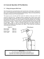
1.0 Installation Instructions
Standard Change-Makers manufactures changers in three main cabinet styles - 1) Frontloading wall or stand mount 2) Free standing consoles and, 3) Thru-the-wall rear load models.
Because physical locations vary, we do not suggest an exact method of installation. To assure
proper operation of your Standard bill changer however, the following general guidelines
should be of help.
1.1
Specifications
Operating Voltage
95 VAC to 130 VAC
Power Consumption
330W with four hoppers dispensing at 120 VAC, 40W when idle
Operating Temperature
0° - 72° C (32° - 150° F)
Humidity
95% non-condensing
1.2
Location of the Machine
The following points should be considered in locating a changer:
1.) Easy accessibility by customers.
2.) Full swing of the door when open.
3.) Proper height from the floor. This will vary depending on the model of the changer.
ANSI specifications for accessibility of the handicapped call for all controls, bill and
coin insertion slots and coin cups to be no higher than 48 inches (1,220 mm) or no
less than 15 inches (380 mm) from the floor.
If someone in a wheelchair is approaching your machine and they are not able to
turn sideways to use your changer, then the user components should be no higher
than 48” from the ground. If they can turn sideways, the user components on the
changer can be raised up to 54”.
4.) This machine is designed for use in protected locations. It should be installed in such
a way as to prevent it from being directly exposed to the outdoor environment.
Standard Change-Makers, Inc. recommends the use of an awning, canopy, or other
protective screen to prevent machine damage from exposure to weather. It is also
recommended that all open holes on the cabinet be sealed to prevent water
intrusion.
4
1.3
Mounting The Machine
For compliance with the Americans with Disabilities Act (ADA) please contact your distributor
for the proper mounting height of your changer. Changers sold with pedestals meet ADA
standards.
Remove all internal shipping restraints from the machine prior to installing the cabinet.
SHIPPING
BRACKET
NOTE
ACCEPTOR
5
If your machine was shipped with the hoppers in place, the hoppers should be removed before
installation. The hopper shipping clips located inside the hopper access door must first be
removed. See Diagram for shipping clip location. If the hoppers have been shipped in
separate carton(s), do not remove or disconnect any components.
Interrupter
Shipping Clip
Press inward at
these locations
1.) Use four ½ inch diameter bolts for mounting.
2.) Make sure that the cabinet is level and the mounting surface is flat.
Caution
Even the slightest uneven surface can cause cabinet distortion when mounting bolts
are tightened. This can cause the doors to fit unevenly when closed. This distortion
can occur even more easily on large cabinets. Should this occur, it may be
necessary to shim one or more of the cabinet corners.
3.) Be sure that the inside of the cabinet that hoppers, stackers and note acceptor are
free of metal shavings and other debris, which might have been introduced in the
mounting process.
4.) Remove all packing materials and shipping straps from the cabinet. Some items
have yellow tags with removal instructions. Multi-compartment stackers have
cardboard spacers, which must be removed before operation.
5.) After installation, replace hoppers or, if they were shipped separately, remove them
from their cartons and install them. Plug in all electrical connectors. (The hopper
connectors are located inside the access door of the hopper.)
6
1.3.1 Mounting The Machine To A Wall (Front Load Models)
1.) Type of wall construction: For maximum security, it is recommended that the
changer be installed on a wall made of cement block, brick or other type of masonry.
A wooden stud wall is acceptable but will not provide the security or strength usually
associated with masonry.
2.) The mounting holes on the back of the changer will accommodate four ½ inch
diameter bolts.
3.) If the wall to which the changer will be mounted does not meet standards in No. 1
above, we recommend the Standard Change-Makers pedestal stand. These are
provided with mounting holes on the top surface for mounting the changer.
Mounting holes are also provided on the bottom for mounting the stand to the floor.
When utilizing the pedestal stand, we recommend that the machine be bolted to the
wall as well as to the stand. This provides a highly secure installation.
WARNING
CHANGERS MOUNTED ON THE PEDESTAL BASES ARE TOP HEAVY.
The changer must be secured to a rigid vertical surface, as well as to
the stand to provide appropriate security, stability, and safety.
4.) If the changer is to be mounted to a post, the post should be sunk in concrete for
stability. It is also recommended that the post be filled with concrete for strength. A
steel plate approximately the same dimensions as the changer should be welded to
the post. Bolt the changer to the steel plate through the four ½ inch mounting holes
drilled into the plate. Tack weld the heads of the mounting bolts to prevent their
removal. The changer can then be secured by four nuts and washers inside the
changer. If this method is not feasible the bolts can be bent after installation to
prevent removal.
CAUTION
We do not recommend welding the cabinet to any kind of mounting. This can cause
unwanted warping of the cabinet as well as internal component damages.
1.3.2 Mounting A Free Standing Machine (Console Models)
The SC90 Series cabinet is designed to sit on the floor. Four ½ inch diameter mounting holes
are inside the bottom section of the cabinet. A locked door provides access for easy
installation. Levelers are included inside the cabinet. Should levelers be needed, there are
four holes in the bottom of the cabinet. Note that an 18 inch space above the cabinet is
required to allow the cabinet top to swing up to facilitate loading the hoppers.
7
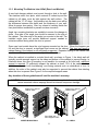
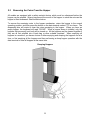
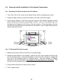
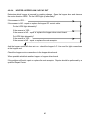
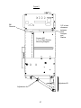
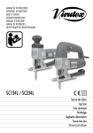
1.3.3 Mounting The Machine Into A Wall (Rear Load Models)
A rear load changer cabinet must mount through a hole in the wall.
The stainless steel front plate, which extends 2 inches beyond the
cabinet on all sides, must be tight against the wall surface. The
cabinet will be 13”-18” deep. Its protrusion into the back room will be
the difference between this depth and the thickness of your wall.
Allow for proper door swing. Also, lay a bead of caulking inside the
front plate before installation to prevent moisture incursion.
FIG. 1
Angle iron mounting brackets are available to secure the changer in
place. One side of the angle iron should be secured to the side of
the cabinet. The other side of the angle iron mounts to the wall. The
installed angle irons will provide additional support needed to
minimize cabinet flexing when the door is opened.
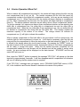
Some rear load models have the coin hoppers mounted on the door. When the hoppers are
full and the door is opened, a significant load occurs on the cabinet. This load can result in
cabinet flexing if the cabinet is not sufficiently supported. Repeated flexing of the cabinet can
result in metal fatigue and stressed weld joints on the cabinet.
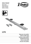
When the cabinet is installed in a cinder block wall, as shown in Figure 1, the block wall will
typically provide enough support on the sides and bottom of the cabinet to prevent flexing. In
locations where this type of mounting is not feasible, for example a 2x4 stud wall, additional
support is required. To sufficiently support the cabinet, at least 75% of the cabinet bottom
should be supported with load-bearing, non-flexing material such as cinderblock or iron. In
addition, the sides of the cabinet must also be supported to prevent the cabinet from twisting
when the door is opened. See Figure 2 for the required support areas.
Any deviation of these guidelines will void the machine’s warranty.
CAUTION: We do not recommend welding the cabinet to any kind of mounting. This can
cause unwanted cabinet warpage as well as internal component damage.
Angle Iron to Secure
Cabinet Sides
Angle Iron to Secure
Cabinet Sides
Steel Shelf with
Steel Support Poles
FIGURE 2
CINDER BLOCK WALL
2 x 4 WALL
8
1.4
Electrical Hook-up
NOTE:
It is recommended that a qualified electrician perform electrical
connections and that you should check local building codes for compliance.
1.) The Cabinet has a cut out for electrical connection. This cut out is sized for ½ inch
conduit fittings. Some models have several cut outs allowing alternate wiring inlets.
2.) It is important to the operation of your changer that wiring be in properly grounded
electrical conduit. (3rd wire ground back to main service panel) We also recommend
that the changer be wired on a dedicated line. A dedicated line is a circuit which has
no other equipment connected on the same circuit breaker or fuse. The purpose of
a dedicated line is to reduce the possibility of line interference, which may cause the
changer to malfunction. If the situation does not allow the recommended installation,
a 3 wire line cord may be substituted. The changer is equipped with an electrical
filter network to condition the line. In order for this filter to function, the machine must
be connected to a good ground. The ground can be checked by measuring the
voltage between the white wire and the green wire. This voltage should never
exceed ½ volt AC. NOTE: See Appendix E for more information.
NOTE: An improperly connected machine may void your warranty
A WORD ABOUT GROUNDING
Please make sure your changer has a good ground. Improper grounding of the
changer will cause erratic operation and is unsafe for the people using the changer.
9
3.) The electrical connections are made in the Power Outlet Filter Box as follows:
A.) Open the cabinet and unplug all cords going to the outlet and remove the front
cover from the Power Outlet Filter box.
B.) Strip the insulation back half an inch on the brown and blue wires coming from
the front panel of the Power Outlet Filter box.
C.) Use wire-nuts to attach the BLUE wire To the BLACK wire and the BROWN wire
TO the WHITE wire. Electrical tape should be used to wrap the wire nuts thereby
ensuring a safer connection.
D.) Place all ground wire lugs over the same stud making sure to place the supplied
lock washer between each ground lug. Secure stack of lugs with a nut.
E.) Place the front cover over the Power Outlet Filter box with the power outlet on
the right side. Make sure that you do not crush the wires. Secure with screws
provided.
F.) With power OFF use an ohmmeter to check the connections. Make sure that
there are no shorts to the cabinet except for the ground connection and that hot
and neutral are not shorted together.
G.) Tighten the screws on all strain reliefs. Plug all cords back into the Outlet and
turn power on to the changer.
10
2.0 General Operation Of The Machine
2.1
Filling the Hoppers With Coins
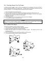
Open the hopper door by using the hole on the front lower face of the hopper to pull the door
open. Some changers have been shipped with a shipping clip in place at the mounting base of
the hopper to prevent the hopper from pivoting during shipping. Remove this clip and test that
the hopper can freely move in a front-back direction.
The hoppers may be removed and filled outside the machine or they may be left in the
machine for filling with coins. All hopper models are equipped with a safety restraint, which
prevents the hopper from being fully tilted out of the machine while, allowing for easier filling of
the hopper(s) in the machine. For coins contained in a bank bag, grasp the neck of the bank
bag and twist it to choke the mouth of the bag. Invert the bag and insert the neck of the bag
into the top of the hopper. Loosen your grip of the bag neck slowly, letting coins feed down
into the hopper. Table 2.1.1 gives a convenient filling level for the various standard size
hoppers. When possible, you can turn your bank bags inside-out and lesson the chance of
small strings and threads from accumulating in your hopper. Clean coffee cans or plastic pails
can also be used to fill hoppers.
Filling Hoppers
Table 2.1.1
Nickel Hopper
3800 coins
Dime Hopper
7300 coins
Quarter Hopper
3100 coins
Dollar Hopper
2400 coins
IMPORTANT
The correct coin must be poured into each hopper.
The hoppers are marked to indicate which coin they will dispense.
Never mix coins or allow foreign material to fall into the hoppers.
11
2.2
Removing the Coins From the Hopper
All models are equipped with a safety restraint device, which must be unfastened before the
hopper can be emptied. Wrap a bag around the mouth of the hopper to catch the coins as the
hopper is tilted downward. See illustration below.
To remove the remaining coins in the hopper mechanism, return the hopper to the normal
operating position, and then press the button on the data terminal marked “F3” two times. The
dispensing disc will rotate to clear the coins remaining in the hopper. When you have an
empty hopper, the keyboard will read “CLEAR”. When a hopper dump is initiated, only the
hoppers that are empty (sold out) will be turned on. All the hoppers may be cleared together if
they are all first emptied into a bank bag or other suitable container. When emptying all
hoppers in a machine, you have a choice of either emptying and dumping the hoppers one at a
time, or first emptying all the hoppers and then performing a dump hopper operation with the
data terminal to clear all hoppers at the same time.
Dumping Hoppers
12
2.3
Removing bills from the stacker
To remove bills from the stacker, pull the release handle down, as shown in drawing below.
CAUTION
The stacker should be supported by one hand before releasing the latch.
SIDE VIEW
SIDE VIEW
13
2.4
Stacker Operation When Full
When a stacker bill compartment becomes full, the stacker will begin placing the bills into the
next compartment that is not yet full. The transfer sequence will be from the lowest bill
compartment number to the higher bill compartment number. Let’s say we are stacking in bill
compartment one (1). When it becomes full, the stacker will begin stacking in compartment
two (2). When compartment two becomes full, the stacker will begin stacking in compartment
three (3). The above statement assumes we are talking about a three compartment stacker.
To give an example, let’s suppose we have a three compartment stacker and are stacking one
dollar bills in compartment one, five dollar bills in compartment two and ten dollar bills in
compartment three. When the one dollar bills fill up compartment one, the one dollar bills will
be stacked in compartment two along with the five dollar bills. This scheme enables the
maximum capacity of the stacker to be utilized. The orange colored full indicator for
compartment one (1) will light to indicate this condition.
When a stacker compartment is filled with bills to the point where it will not accept more, the
indicator light for that compartment is turned on. It will then be necessary, after the bills are
removed from the compartment to follow the instruction on the label shown in Figure 2.4.1, that
is affixed to the stacker above the circuit board housing. By pressing the “RESET” button on
the data terminal all full box indicators will be cleared and turned off, and these compartments
will be ready to accept bills again. When the bill stacker becomes completely full (all
compartments loaded) the note acceptor will be disabled and will be unable to accept more
money. An error message will be displayed on the data terminal. “STACKER” and the red
status LED will come on.
Now, when the “RESET” button is pressed, the message “STK FULL” will appear on the data
terminal for approximately 4 seconds. It will then disappear and all compartment full indicators
will turn off indicating that the stacker reset is complete.
If the “STK FULL” message does not appear, turn to TROUBLE SHOOTING section, LOCKUP, in the installation and Service Manual to determine the cause of the problem.
Figure 2.4.1
14
2.5
Auditing Your Machine
Your machine can be audited (counts of all monies in and out) by use of the hand held
data terminal. A total count of all monies accepted and dispensed can be tracked using
this device. For a detailed explanation for viewing each audit total, see the Data Terminal
Overview section of this manual.
2.6
Servicing your machine
In the event of a malfunction, the data terminal can be used to provide you with the
necessary information needed to diagnose the failure source. For a detailed explanation
on how to view errors or perform diagnostics, see the Data Terminal Overview section of
this manual.
15
3.0 Programming and Auditing
3.1
Data Terminal Diagram
LCD
DISPLAY
FUNCTION
KEYS
HELP
KEY
NUMERIC
KEYPAD
CABLE CONNECTOR
TO CONTROLLER
BOARD
ONLY ON DATA TERMINALS
P/N 5M00169
Special Note for using Data Terminals P/N 5M00169
The following table shows the mode switches for the data terminal. Be sure to set the data
terminal to the correct mode before connecting it to the changer.
SW1
OFF
OFF
ON
ON
SW2
OFF
ON
OFF
ON
OPERATING MODE
KeepTrac
System 600/500
Economy Changer Plus
RESERVED
16
3.2
Data Terminal Operating Instructions
The DATA TERMINAL is designed to allow you to change your machine programs, view an
error log, display the note acceptors current software version, perform automatic system
calibration and give you a complete audit of the machines transactions.
The top line on the display is called the “message line” and will give information or ask a
question. The bottom line is called the “action line” and will display the key choices that are
available to you for the question asked.
When you turn on your machine the Data Terminal will display the following:
Message line ;
“Main Menu”
Action Line ;
“F1 = Program”
“F2 = Diagnostics”
“F3 = Audit”
“F4 = Options”
“F5 = Reset”
“ ? “ = Help”
By pressing the FUNCTION KEY specified you will access the desired MENU (Programming,
Diagnostics, Audit, Reset). As an example, by pressing the F1 key you will access the
Programming Menu. Once in the desired Menu your Data Terminal will display a question or
give you information.
3.3
Menu Choices
There are four MENUS available to you. Within each of the menus are SUB MENUS;
PROGRAMMING (F1)
Bills Accepted / Security levels
Setting Hopper Values
Coin Dispense
Bill Dispense
Stacker Settings
Accumulate Settings
DIAGNOSTICS (F2)
View Errors
Auto Calibration
Software Version
AUDIT (F3)
View Audit
Last Bill In
Dump Hoppers
Clear Audit
OPTIONS (F4)
Hopper Alarm
Setup
Time and Date
Personal Identification Number
17
3.4
Programming Menu (Press F1)
YOU MAY STEP THROUGH EACH SUB MENU BY PRESSING F2. YOU MAY EXIT THIS
MENU AT ANY TIME BY PUSHING THE F5 (MAIN MENU) KEY. Pressing the “?” will give
help.
The programming menu allows you to select the bills you want to accept, the security level you
want for each bill accepted, the value of the coins in each hopper, how you want the change
dispensed, which hoppers you want the change dispensed from, and into which stacker
compartment you want the bills placed. If your machine is equipped with a coin acceptor OR if
you want to accumulate to a specific amount (e.g.; $2.50) before dispensing a ticket or token
you may want to modify the accumulate functions.
There are FIVE SUB-MENUS
3.4.1 Bill Acceptance / Security Level
Your Data Terminal will display the following to see if you want to be in this sub-menu. “Bills
accepted?” F1=YES F2=NO F5=MAIN MENU. If your answer is “YES”, you will be asked by
the Data Terminal which bill denominations you want to accept. As an example, the first bill on
your screen will be the $1. If you want to accept this bill press F1 for “YES” or F2 for “NO”.
This will be followed by a question on the Security Level you want for all $1 bills. “0” is the
lowest and “9” is the highest. Most machines are factory set at “5”. You may change the
security level by entering 0 through 9 to set the new security level that you prefer. Pressing F1
“ACCEPT” will set the new security level and bring up the next bill for your consideration.
18
3.4.2 Hopper Values
Your Data Terminal will display the following question to determine if you want to be in this
sub-menu; “Set Hop Values?” F1=YES F2=NO F5=MAIN MENU .
If your answer is YES then the following will apply.
Each hopper in your machine must be given a ‘value’ for the coin that will be dispensed. If a
value is not given to a hopper the machine will assume that the hopper is not in
operation and will not allow it to dispense coins. In most cases this value is .25 (25
cents). If you are using nickel, dime, or dollar hoppers, the appropriate values would be .05,
.10 or 1.00. Tokens or tickets are given their sale value. For Example: $1.50 would have a 150
value.
Your Data Terminal will display a message asking you to place a value on each of your
hoppers. This has already been done at the factory, but if you desire to change it press F2
“CLEAR”, change the value, then press F1 “ACCEPT”. You will want to program only
those hoppers that are physically in your machine. If it is a two (2) hopper machine,
program the value of hoppers A & B only. If it is a three (3) or four (4) hopper machine
program the value for the C hopper and/or the D hopper.
WARNING
Should an existing hopper in your changer be programmed to a value of 000, the hardware
dispense watchdog circuit will not monitor for dispenses from that hopper. Therefore a “jack
potting” condition could occur if that hopper’s circuits malfunction. If a hopper’s value must be
set to 000, it is recommended that the hopper should be emptied of all coins or that the hopper
cable be disconnected from the note acceptor and be replaced with the by-pass plug included
in the owner’s packet.
3.4.3 Dispense Amounts
In this operation you are being asked to determine how many coins you want dispensed from
each hopper for each denomination of coin and bill accepted. It is usually best, when all of
your hoppers have the same value, to dispense coins evenly from each hopper. This reduces
the wear and tear on any single hopper and speeds up the dispense cycle. As an example, for
a one dollar dispense in a two hopper machine that contains all quarters you will want to
program 2 quarters from hopper “A” and 2 quarters from hopper “B”.
“Coin Disp?” F1=YES F2=NO F5=MAIN MENU
If you do not have a coin acceptor on your machine press F2 “NO” for the question. If you do
have a coin acceptor you will want to program acceptance of nickels, dimes, quarters and
dollars.
“Bill Disp?” F1=YES F2=NO F5=MAIN MENU
You will be asked to determine how many coins you want dispensed from each hopper for the
bill denominations you have selected to accept. If you are satisfied that the dispense amount
is correct press F1 “ACCEPT”. If you want to change the dispense amount press F2 “CLEAR”,
enter the new setting, then press F1 “ACCEPT”.
19
3.4.4 Stacker Settings
The Data Terminal will display “Stacker settings?” F1=YES F2=NO F5=MAIN MENU.
If you want to enter this sub-menu press F1 “YES”.
After being accepted, all bills are placed in a “stacker”. These are available in a one (1),
two(2), or three (3) compartment configuration. If your machine has a one (1) compartment
stacker, all of your bills will automatically be placed in it. If you have a two (2) or three (3)
compartment stacker, you can program into which compartment you want the bills placed. To
reduce wear and tear on your stacker motor, it is best to have the denomination that you
accept the most of placed in the #1 compartment. You will be asked into which compartment
you want each bill denomination placed. If you are satisfied with the current program simply
press F1 “ACCEPT” and it will be retained. If you want to change the current program press
F2 “CLEAR”, enter the number corresponding to that box and press F1 “ACCEPT” to set the
option. Example: For box 2, press “2”.
3.4.5 Accumulate Settings
The Data Terminal will display the following message to determine if you want to enter this
sub-menu “accum settings?” F1=YES F2=NO F5=MAIN MENU.
This function is used only when your machine is equipped with a coin acceptor or when you
require an accumulation to a specific amount before dispensing a token or ticket. You will be
asked to specify the amount you want to accumulate before a coin, token or ticket is
dispensed. If the amount showing is correct press F1 “ACCEPT”. If not, press F2 “CLEAR”,
enter the necessary change and press F1 “ACCEPT”.
You will next be asked which hopper(s) to dispense from and how many tokens or tickets you
want to dispense for the accumulated amount that you have specified. Note: Dispensing
devices such as card or ticket dispensers are seen as hoppers to the acceptor.
20
3.5
DIAGNOSTIC MENU (F2)
The DIAGNOSTIC MENU allows you to view the error log, display the note acceptors software
version, display the Data Terminals software version and perform Automatic Calibration.
There are FOUR SUB-MENUS for this section;
3.5.1 View Errors (F1)
This sub-menu will allow you to view the ‘errors’ or ‘problems’ that your machine may have
encountered. By pushing F3 “CONTINUE” you can scroll through each of the recorded
messages in this manner. Pressing “F2” once will display the time the entry was logged.
Pressing “F2” again will display the date for the entry. Pressing “F2” a third time will display
the entry again. At the end of the messages you will have a total error count. See
Maintenance and Troubleshooting section to determine what each message indicates.
Pressing “F4” will allow you to clear the error log, while F5 returns you to the main menu and
retains the current error log history.
3.5.2 Auto Calibration (F2)
In order to perform an AUTOMATIC CALIBRATION a calibration card is necessary. See the
DIAGNOSTIC and TROUBLESHOOTING section in this manual for complete directions.
3.5.3 Software Version (F3)
In this sub-menu your Data Terminal will display the software version that is in your note
acceptor (Press F1). You can also display the software version that is installed in your Data
Terminal (Press F2). This information is important when describing a problem to our Service
Center.
3.5.4 SERVICE MENU (F4)
3.5.4.1 Clear All (F1)
This will clear all audits, The Last Bill In log and the Error log.
3.5.4.2 Display Mag (F2)
This applies to the System 600 that has a magnetic security sensor. This is a factory setting
and should be adjusted only by a trained technician.
21
3.6
Audit Menu (Press F3)
The Audit Menu allows you to access the data required for auditing purposes. It will provide
you with a total for coins accepted by your coin acceptor, display how many bills by
denomination the machine has accepted and how many coins have been dispensed by each
hopper. It will also allow you to review the last bills accepted, dump all hoppers and clear the
audit.
3.6.1 View Audit (F1)
By pressing F1 "View audit" you will be able to see the total money accepted by the machine
(Money=$XXX.XX). Press F3 "Continue" to view the dollar amount of the coins your machine
has accepted through the coin acceptor (Coins = $XXX.XX). Press F3 "Continue" to view the
total dollar amount of the bills your machine has accepted through the bill acceptor (Bills =
$XXX.XX). Press F3 "Continue" to view the dollar amount of the credits your machine has
accepted through a credit card reader (Credits=$XXX.XX). Press F3 "Continue" to view the
number of each denomination that your machine has accepted. Continually pressing F3
"Continue" will step you through each denomination.
After reviewing the bill denomiation audit the Data Terminal will start to display the items
dispensed from each dispenser. Example: Disp Hop A=2852 is refering to the number of coins
or tokens dispensed from that dispenser.
By pressing F4 "Clear audit" you can clear the machine audit while viewing the audit.
3.6.2 Last Bills In (F2)
You can step through a listing of the last ten bills by first entering F2 “LAST BILLS IN” then
pushing F3 to display bills individually. Pressing “F2” once will display the time the entry was
logged. Pressing “F2” again will display the date for the entry. Pressing “F2” a third time will
display the entry again. Number 1 shows the most recent bill accepted.
3.6.3 Dump Hoppers (F3)
You can, under certain conditions, allow your machine to dispense all remaining coins in the
hoppers. Please review your Owners Manual for details.
3.6.4 Print Audit (F4)
This allows the printing of different types of audits.
3.6.4.1 Print Audit (F1)
Prints the current machine audit. You must have a printer and the printer must be installed.
3.6.4.2 Print Door (F2)
Prints all of the door audits. You must have a printer and the printer must be installed.
22
3.7
Options Menu (PRESS F4)
3.7.1 HOPPER ALARM (F1)
This feature is only used by the KEEPTRAC system and allows users to set an alarm condition
that activates when the hopper is nearing a soldout state. See KEEPTRAC manual for
additional information. If not used set to zero.
3.7.2 SETUP (F2)
3.7.2.1 Multiple Country Support (Factory default setting = USA)
This option changes the country/language the Data Terminal is programming for. Example: If
set to U.S. the programmable bills will be $1, $5, $10, and $20. If set to Mexico the
programmable bills will be 10peso, 20peso, 50peso, 100peso, 200peso, 500peso. THIS
SETTING MUST MATCH COUNTRY OF THE NOTE ACCEPTOR SOFTWARE TO WORK
CORRECTLY.
Current country/language options are U.S./English, Canada/English,
Canada/French, and Mexico/Spanish.
3.7.2.2 Tamper Time (Factory default setting = 15 minutes)
This feature resets a tamper error after a set time has elapsed. Setting the time value to “0”
will disable this feature. Maximum time limit is 99 minutes. Pressing RESET (F4) on the Data
Terminal will also clear a tamper error if this feature is enabled.
3.7.2.3 Hopper Transfer (Factory default setting = Yes)
On a soldout, lockup, or error, the active hopper will transfer to another hopper(s) of an equal
or lesser value(s). It will then complete the original transaction via the new hopper(s) and
continue to perform until the soldout, lockout or error condition in the out of service hopper is
rectified. Should the second hopper or even a third hopper fail through one of the above
conditions an automatic transfer will take place to the next available hopper(s). If the lowest
valued hopper in the unit goes out of service for any of the above conditions the changer will
go out of service.
3.7.2.4 Kill Relay (Factory default setting = Yes)
Additional jackpot protection is available through a Kill Relay option. This option cuts power to
the hoppers when they are not in use. Thus preventing the possibility of a hopper turning on
due to some external force (tampering, acts of god). This option should not be used with tower
lights, ticket dispensers, or card dispensers as it will interfere with the proper operation of
these devices.
3.7.2.5 Hold Escrow(Factory default setting = No)
During a coin accumulation through the coin acceptor (example: 2 dimes + 1 nickel = quarter
payout) a customer may deposit three dimes. If a five-cent hopper is not available the nickel
can now be (a) held in escrow for the next customer if set to YES or (b) simply retained by the
machine and not held in the escrow if set to NO.
23
3.7.2.6 Accumulate Override (Factory default setting = No)
This feature allows a deposited bill, which is of a greater value than the preprogrammed
accumulate value, to override a previous deposit that was less than the accumulate value.
Example: A token machine is set for the following accumulate value = $1.00 accumulate
payout = 4 tokens, $5.00 bill payout = 22 tokens. A customer deposits a quarter and then
deposits a $5 bill; the payout could be (a) 22 tokens + quarter if accumulate override is set to
NO, or (b) 4 tokens + 17 quarters if accumulate override is set to YES.
3.7.2.7 Power Reset (Factory default setting = No)
This feature allows errors to be cleared by cycling the power OFF then ON rather than clearing
the error using the Data Terminal. This feature is useful when the machine is to be operated
without a Data Terminal.
3.7.2.8 Mag Sec Off (Factory default setting = No)
This feature allows the magnetic security sensor to be disabled. Warning – Turning this off will
reduce the machine’s ability to reject certain types of counterfeit bills.
3.7.2.9 Tamper Sec (Factory default setting = Hi)
This feature allows you to shut off certain anti-stringing checks that may results in nuisance
tamper errors.
Warning – Setting this to Low will reduce the effectiveness of the anti-stringing security
features. If this feature is used the Fast Vend Shut Off feature should be enabled.
3.7.2.10 Card Reader? (Factory default setting = No)
This is an installation flag used by the changer. If you have a Card Reader set this to Yes.
The Card Reader will not operate correctly unless this is set to Yes. Setting this to Yes if there
is no card reader will impair System performance.
3.7.2.11 Printer? (Factory default setting = No)
This is an installation flag used by the changer. If you have a printer set this to Yes.
The printer will not operate correctly unless this is set to Yes. Setting this to Yes if there is no
printer will impair System performance.
3.7.2.12 Fast Vend Shutoff (Factory default setting = disabled)
This feature provides additional security against theft by identifying unusual deposit patterns.
In other words, if more money than normal is coming into the machine this feature can detect it
and protect the machine by automatically taking it off-line. The unusual pattern is based on a
maximum number (programmed) of any denomination bill deposited in a given (programmed)
time frame. Whether under “Each Bill” or “Total Bills” the first entry is the number of bills
allowed to be accepted. The second entry is the time allowed in minutes.
Example: The machine is set to take a maximum of ten $5.00 bills in 20
minutes. If eleven $5.00 bill’s are accepted in less than twenty minutes the
machine will automatically go out of service, retain the last bill inserted, finish
the payout, displays Fast Vend on the Data Terminal (if connected) and creates
a Fast Vend entry in the error log.
24
Important Notes regarding the Fast Vend Shut Off Feature:
• The Fast Vend condition can be reset (machine back into service) by pressing the reset
button.
• The settings for this feature should be based on the machines highest normal volume
usage.
• The values programmed for “Total Bills” will take precedence over “Each Bill”.
3.7.2.13 Machine ID=0 (Factory default setting = 0)
A unique four digit number can be entered. This number is used in the audit print out by the
owner to identify different machines.
3.7.3 Time and Date (F3):
This choice allows you to set the correct time and date for the real time clock in the changer.
First you will be shown the current date. If the date is correct press F1 “YES” and then you
will be shown the current time. If you answer F2 “NO” to either of these you will be prompted
to enter the corresponding corrected time and/or date. Please adjust for daylight savings time.
3.7.4 Personal Identification Number “PIN” (F4):
The Personal Identification Number (PIN) is used to protect your machine from unauthorized
access. The PIN prevents access to the programming menu, clearing the audit, clearing the
last bill in log, and clearing error log. Only a user who knows the PIN# will be able to enter
these areas.
To set a PIN# press F4 (Options) at the main menu. You will then be asked “Change PIN?”.
Press F1 for yes. You will then be asked to enter your four digit PIN. Press F1 to accept. Next
you will be asked to re-enter your PIN, press F1 to accept, and confirm the number you
entered. The PIN is set at that point and any attempt to change the programming or clear one
of the audits will required the PIN number to be entered first.
Should you decide that a PIN is no longer necessary you may clear a PIN. Enter the Options
Menu (F4). Select “Change PIN”(F1). Enter your old PIN then enter “0000” for the new PIN.
Enter “0000” again when asked to confirm new PIN. This will allow you to use your Data
Terminal without using a PIN to change the programming or clearing audit information.
If you forget your PIN you will need to return your Data Terminal to an authorized service
center to have the PIN cleared.
25
4.0 Maintenance and Trouble Shooting
Caution Electrostatic Discharge!
Electrostatic discharge (ESD) is the release of a static charge. A common example of ESD is
a person walking across a carpeted floor then grabbing a doorknob. This type of discharge is
very detrimental to electronic components. The damage caused by ESD can be total failure of
the component or degradation within the component, which may weaken it until it eventually
fails. Your changer has been carefully designed to reduce the possibility of ESD damage to its
components. Care should be taken when servicing the machine or when handling the
components, to avoid ESD. NEVER HANDLE THE INTERNAL CIRCUIT BOARDS WITHOUT
FOLLOWING THE ESD PROTECTION PROCEDURES OUTLINED BELOW!
1) Before disconnecting any connectors, place one hand on the housing of the component or
the cabinet. This will bleed off any static charge you have developed. If possible, keep this
hand in contact with the chassis at all times.
2) Never touch the internal circuit boards unless you are wearing a ground strap. (Ground
straps are available from most electronic stores.) In the event that a ground strap is not
available, you can hold onto the cabinet of the machine or chassis of the component you
are servicing. If this method is used, you should be in contact with ground at all times.
3) NEVER carry or ship an electronic board or component without using a static shielding bag
or container. In the event a static shielding bag is not available, aluminum foil may be
used.
4) Use only anti-static shipping and packing materials. Anti-static shipping materials can be
identified by a pink color. Newsprint is a preferred substitute. Never use white ‘peanuts’ for
packing. When these rub together, they generate very high electrostatic charges.
5) NEVER attempt to repair the boards away from a static safe workstation. The minimum
configuration of a static safe workstation is a properly grounded static dissipation mat and a
ground strap. An ion blower is also recommended for added protection.
Contact the factory for more information on ESD.
26
4.1
Note Acceptor Maintenance
The note acceptor does not require frequent periodic maintenance. However, it is always a
good preventative measure to check the bill acceptor path for dirt and debris each time you are
in the machine. If the note acceptor becomes selective of the notes accepted (poor
acceptance), refer to the Poor bill acceptance section of this manual.
Removing debris or a jammed bill from the bill acceptor path.
To gain access to the bill path for cleaning or removal of a jammed bill, perform the following
steps:
1. Release the upper track latch by pulling the latch handle towards the rear of the note
acceptor. Note the position of the latch before opening so that you can confirm when it is
closed properly.
2. Continue pulling the latch towards the rear of the acceptor until the upper track lifts up
enough to expose the bill path.
3. Remove the debris or jammed bill.
4. Use a clean damp cloth to clean the upper and lower track windows.
5. To return the track to the closed position, push down on the front of the track. The latch is
spring loaded and therefore will automatically lock when the track is in the proper position.
This can be confirmed by noting the position of the latch handle; it should return to the
same position it was in before the latch was pulled back.
4.1.1 Note Acceptor Repairs
Any repair or adjustments to the note acceptor (other than auto-calibration) should be
performed by qualified service personnel. Some repairs require specialized tools and/or
complicated adjustment procedures.
4.2
Bill Stacker Maintenance
The bill stacker requires very little maintenance. A good annual maintenance routine would be
to remove the bill stacker and use air pressure to blow out the debris that has accumulated.
Next, the guide bars and ram slide should be cleaned with a soft, clean cloth. It’s best to
remove the stacker bill box to expose these components.
NOTE: No lubricants of any type should be used on any of the moving parts.
4.3
Coin Hopper Maintenance
Occasionally you will want to check the inside of your hopper(s) for pieces of string or other
debris from money bags or dirty coins. When your power is OFF simply empty the hopper and
take a look inside. Is the agitator clean? Do you see any obvious dirt or obstruction? If so
remove it. Open the bottom door and clean the gears and the hopper interrupter (See diagram
on page 6). Once again, no lubrication is necessary on the hopper mechanisms.
27
4.4
Removal and Re-installation of the System Components
4.4.1 Removing The Note Acceptor From The Cabinet
1. Turn off the 120 volt A.C. power at the System Power Source using the power switch.
2. Unplug all cable connectors, which are located on the side of the note acceptor.
3. Locate the two detents on the front of the note acceptor. (The detents are made of black
plastic material and have pull rings attached to them). Push in on the detents with your
forefingers and lift upward on the bottom of the note acceptor. The note acceptor will come
free from its mount and may be removed from the cabinet. Note: A slight rocking motions
tends to help with removal.
tandard
CHANGE-MAKERS, INC.
)
INDIANAPOLIS, INDIANA
SYSTEM 600 FST
Press
in here
(
Press
in here
4.4.2 To Re-install The Note Acceptor
1. Make sure the power switch is turned off on the power supply.
2. Depressing both detents on the acceptor, position the front of the acceptor (bill input end)
into the mounting frame. Now push downward on the front of the acceptor to engage the
front rod in the mounting hooks of mounting frame. Once the acceptor is properly
positioned in the mounting frame, pull outward on the rings attached to the detents. This
will insure that the acceptor has been locked in place.
3. Plug all cable connectors into their proper locations.
4. Turn on power switch
28
4.4.3
Removing a Hopper From The Changer
In normal use the hopper is free to pivot for emptying but is retained at the pivot so that it
cannot accidentally fall from the hopper shelf. A hopper may be completely removed from the
machine if desired. The following simple procedure should be followed:
1. Turn off the power at the power source.
2. Open the hopper access door. Remove the shipping clip if present (See section 1.2).
3. Locate the two connectors and cables which connect the hopper to the rest of the system.
Disconnect the hopper from the rest of the system.
4. Tilt hopper forward.
5. Lift the hopper from the locking base and remove from the changer.
6. To re-install the hopper reverse this order.
Caution
When removing several hoppers, make sure you re-install and reconnect them in the proper
location. If you do not do so, the dispense of change may be incorrect.
4.4.4 To Remove The Stacker
To remove the stacker from the stacker mounting:
1. Turn off the A.C. at the System Power Source power box.
2. Unplug the Stacker Cable from the Note Acceptor.
3. Reach under the stacker and release the stacker support. The stacker will tilt to the
unloading position.
4. Push in on the stacker latch and lift the stacker out of the mount.
5. To re-install the stacker reverse the above procedure.
29
4.5
Troubleshooting The Machine
Your machine is equipped with a variety of diagnostic aids. These consist of a series of LED
indicators on the note acceptor, hoppers, and stacker and a readout on the data terminal,
which displays error messages as required. If a regular maintenance schedule is followed, the
need for troubleshooting and repair should be greatly reduced.
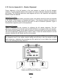
4.5.1 Using the LED Indicators to Troubleshoot
There are a number of LED indicators to aid in diagnosing faults in the system. The LEDS are
placed in three locations; the note acceptor, the bill stacker, and the hopper electronics board.
The door of the hopper must be opened to show the hopper electronics board housing. The
drawings below indicate the exact location of the LEDS.
R= Red
HOPPER LEDS
DIAGRAM A
G= Green
(4
PLACES)
VERIFIER LED LOCATIONS
O= Orange
HOPPERS
G COINS G COINS G COINS G
R INT. R INT. R INT. R
A
B
C
D
P28 P29 P30 P31
COINS
INT.
KEYBOARD
P24
A
B
C
HOPPERS
COIN INPUTS
5 10 25 $1
O O O O
P
C
A
O
N
I
E
N
L
P27
COIN PANEL
LEDS
(4 PLACES)
D
VER. POWER
P26
STACKER
P25
NOTE: TURN OFF POWER. DEPRESS LOCKING TAB TO UNPLUG CABLES.
DIAGRAM B
STACKER LED LOCATIONS
STATUS
LEDS
(5 PLACES)
DIAGRAM C
HOPPER LED LOCATIONS
R R
STATUS
LEDS
(2 PLACES)
30
Acceptor LED Table
ACCEPTOR LEDS
GREEN
ON
ON
OFF
RED
OFF
FLASH
ON
ON
OFF
ON
OFF
OFF
OFF
Hopper LED Table
HOPPER LEDS
DIRECTION
RED
RED
(left)
(right)
ON
OFF
OFF
ON
Stacker LED Table
STACKER LEDS
NAME
Stacking
Status
Ready
3 Compartment Full
1 Compartment Full
2 Compartment Full
DIAGRAM A
OPERATING CONDITION
Condition normal
Normal dispense
Hopper not present in the changer.
Loose connector in the hopper.
Interrupter blocked or defective
Hopper out of change.
Hopper does not have 120 volt power.
Bypass jumper installed, power on.
DIAGRAM C
OPERATING CONDITION
Motor is running (Clockwise) CW
Motor is running (Counter Clockwise) CCW
DIAGRAM B
OPERATING CONDITION
COLOR
RED
RED
GREEN
ORANGE
ORANGE
ORANGE
FUNCTION
On when Stacker is cycling (**)
On when all compartments are full (**)
Flashing for normal operation
On when Full or Out of Service (*)
On when Full or Out of Service
On when Full or Out of Service (*)
4.5.2 Coin Panel Lights
The Coin Inputs are each indicated by an ORANGE LED for the particular coin input. The
LED’s are located on the interface side of the note acceptor (Diagram A). See diagram of the
verifier LED locations. The ORANGE LEDS are on and blink off for each coin deposited.
(*) Not installed on One Compartment Stackers
(**) Both RED LED’S on shows Lock-up
31
Example 1: Checking the Coin Acceptor with the LED Indicators. (4.5.1 Diagram A)
If your machine has a Coin Acceptor and you wish to check it out for proper operation. Insert
coins into the coin slot while watching the LED indicators marked “Coin Inputs” which are on
the Note Acceptor. If the orange LED is blinking off momentarily when the coin is accepted,
the coin acceptor is signaling the Note Acceptor that a coin has been detected. You must
watch the correct LED, for example if you are dropping quarters through the panel, watch the
orange LED marked 25 cents.
Test the coin acceptor with all four types of coins for a complete test. When you have finished
the ‘drop through test, ‘push the money return button and note the condition of all the LEDS.
All of the LEDS should go off when the money return or escrow button is pushed.
Example2: Checking the hopper with the LED indicators. (4.5.1 Diagram A)
Just below the green LEDS on the note acceptor, there is a red LED that will flash for each
coin the hopper dispenses. Insert a bill into the note acceptor. The red LEDS should flash on
momentarily for each coin that is dispensed from each hopper in response to the acceptance
of the bill.
If the red LEDS flash the correct number of times for each coin dropped, operation of the
acceptor and the hopper is normal. As an extra check, count the coins dispensed to see if the
number is correct.
If the number of red flashes is not correct, or if you see the red LED is not flashing on at all,
you need to check the interrupter (INT) of the hopper. (4.5.1 Diagram C)
NOTES: The examples above have been included to illustrate the process of using the LED
indicators to help with troubleshooting. It should be realized that only two possible problems
have been described and that many other combinations of LED indications are possible.
32
4.6
Error Codes
The note acceptor is designed to deliver error messages to the display unit on the data
terminal. A list of the error messages as they would appear on the display is as follows:
ACCEPTOR
BIL HELD
PWRFAULT
TAMPER
DISP ERR
DATA BAD
SOLD OUT
CLEAR - not a fault
ERROR A
ERROR B
ERROR C
ERROR D
STACKER
STK FULL—not a fault
HOPPER
FAST VEND
WATCHDOG
The various machine conditions causing each message to be displayed are listed below. The
troubleshooting chart for the error codes is section 4.8.
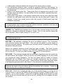
4.7
Meaning of the Error Codes
ACCEPTOR—This message is displayed when the Note Acceptor tries to reject a bill or bogus
paper and the bill or paper jams in the drive rollers during the reject action. In an attempt to
clear itself, the Note Acceptor will go into a progressive reversing action. Thirty-two reversals
will be made, if necessary, to clear the jam condition. At the end of the thirty-two clearing
attempts, the Note Acceptor will make an attempt to deposit the paper or bill in the Bill Stacker.
If it is successful in this action, the display will read “BIL HELD” and the changer will stay
operational. If the Note Acceptor cannot deposit the paper or bill in the stacker, and it has not
been successful in rejecting the bill, the display will read “ACCEPTOR” and the machine will go
out of service.
In either case there will be no payout of change at this point.
BIL HELD—This message was referred to earlier under the heading “ACCEPTOR”. It means
that the note acceptor cleared a jam condition by accepting a paper or bogus bill after thirtytwo attempts to reject it. It did not pay out, and the changer continues to function.
PWRFAULT— This message is displayed when the note acceptor detects power interruptions
that exceed our recommendations. These “interruptions” of power can have many sources.
Some of the more common are listed below along with possible remedies.
33
1. A bad ground connection between the changer and it’s primary source of power.
2. Line interference (electrical “noise”) caused by equipment external to the changer. It’s
recommended that the changer be connected to a dedicated line to reduce the possibility of
line interference.
3. Failure of the internal power filter. These power filters will degrade over a period of time
and may need to be replaced. An external filter, like the ones used for personal computers,
may be substituted.
4. A bad power supply board. If the problem continues after the first three steps have been
followed, the main power board inside the power box may be failing and of need to be
replaced. Contact your nearest service center and request a 40-watt power board and
installation instructions.
CAUTION
It is recommended that a qualified electrician perform electrical connections and that you
should check local building codes for compliance.
TAMPER—The TAMPER error indicates that a bill has been removed through the bill path
backwards, indicating an attempted ‘stringing’ or ‘taping.’ This is a very sensitive setting and
may be adjusted. Refer to option settings 3.7.2.2 and 3.7.2.9.
NOTE: Your acceptor can store up to 50 error codes to help identify problems. See 3.5.1 in
your programming section.
DISP ERR – This message is displayed for one of two different reasons. First, the system
micro-controller memory may have failed. This error can be caused by power surges or
improper equipment handling. The system micro-controller should be replaced prior to putting
the machine back into service.
Second, the dispense watchdog circuitry may have been activated. This circuit protects
against coin dispense errors or mispays. The DISP ERR message will cause the machine to
go out of service. You must turn power off then on and press F5 to reset this error.
DATA BAD – This message indicates that the information, programmed into the machine by
the data terminal, has changed. When you see the DATA BAD message, do not fail to check
your programmed values completely. You may find values (such as number of quarters
dispensed) that are different from those you originally programmed into the machine,
reprogram those values so they are correct. These conditions can be caused by power surges
or an improperly grounded circuit. (See Section 1.3 for information on electrical hookups)
CAUTION
Determine the cause of this error before placing the machine back in service. Contact your
nearest service office for additional information.
SOLD OUT – SOLD OUT is displayed when one of the machine hoppers is running low on
coins and there is a risk that the machine will shortchange a customer if hopper transfer is not
selected. It is not a fault condition. In the sold out mode the changer will not accept any more
money and the out-of-service lamp will flash on and off. Adding coins to the hoppers will reset
the condition.
34
CLEAR – This message is not really an error code but an operating instruction. It is triggered
by the completion of the hopper dump cycle and simply means the hopper has been cleared of
coins.
ERROR A, ERROR B, ERROR C, or ERROR D – These ERROR messages all refer to an
incorrect payout made by hopper A, B, C, or D. This ERROR message could also be caused
by a malfunction of the hopper such as a bad hopper interrupter component or a defective
hopper drive board. The machine is shut down for any ERROR A, B, C, or D.
STACKER – This message is sent to the display whenever a mechanical or electrical condition
causes a stacker malfunction. The electrical drive to the stacker motor is halted to prevent
motor damage. This message could also indicate that the BILL STACKER is full. See STK
FULL.
STK FULL – This message indicates that the stacker is full of bills. In the case of a multicompartment stacker it indicates that all of the bill compartments are full. When this condition
is reached, the changer will not take any more bills. This message will appear for
approximately 4 seconds upon resetting the Note Acceptor from a stacker error caused by a
stacker full condition.
HOPPER – This message is sent to the display whenever a mechanical or electrical condition
causes a hopper malfunction. The electrical drive to the hopper motor is halted to prevent
motor damage.
FAST VEND – This message will be displayed if the bill denomination accepted exceeds the
limits set by programming. See 3.7.2.10 options menu for programming.
WATCHDOG – This message is sent to the display whenever an unexpected reset of the
changer occurs. This is a non-fatal error indicating a possible power supply problem or a
supply line problem.
4.8
Error Code Troubleshooting Guide
4.8.1 ACCEPTOR
The ACCEPTOR error indicates that the track sensors are blocked by something in the track.
The acceptor will try to reject the item through a series of motor reversals. If it is unable to
reject the item or pass the item into the stacker, the ACCEPTOR error is displayed. The note
acceptor’s upper track is hinged so that the upper track section can be opened to expose the
bill channel. A step by step procedure is given below:
Note: You don’t have to remove the acceptor from the cabinet to clear a jam.
35
1. Release the upper track latch by pulling the latch handle towards the rear of the note
acceptor. Note the position of the latch so that you can confirm when it is closed properly.
2. Continue pulling the latch towards the rear of the acceptor until the upper track lifts up
enough to expose the bill path.
3. Remove the obstacle or jammed bill.
4. To return the track to the closed position, push down on the front of the track. The latch is
spring loaded and therefore will automatically lock when the track is in the proper position.
This can be confirmed by noting the position of the latch handle; it should return to the
same position it was in before the latch was pulled back.
Once the obstruction has been removed and the track properly latched, press the F4 (reset)
button on the data terminal to reset the error message and put the acceptor back into service.
4.8.2 BIL HELD
The BIL HELD error indicates that the note acceptor was unable to reject a bill after a series of
motor reversals. In this case the acceptor passes the bill into the stacker without vending for
that bill. Causes for this type of error are typically found with obstructions in the bill path.(See
section 4.8.1 for instructions on how to clear a jam). Also check the note acceptor to see that it
is properly mounted in the changer cabinet. (See section 4.4.2 for instructions on installing the
Release this
handle to expose
track sensors
36
note acceptor). Dirt buildup on the roller assemblies can result in bill slippage, which can cause
this type of error. Dirt may be removed by cleaning the roller assemblies with a damp cloth.
Make sure power is turned off and that the note acceptor has dried completely before power is
returned.
NOTE: Do not use any spray cleaners directly on the note acceptor.
4.8.3 TAMPER
The TAMPER error indicates that an attempt to remove the bill through the bill path backwards
has occurred. Look for evidence such as tape or string in the bill path. Also look for torn
pieces of a bill within the stacker. Check your audit. If it does not match, contact your nearest
Standard Change-Makers service center. If it does match, check for obstructions within the bill
path. (See section 4.8.1 for instructions on how to clear a jam). Check the security gate, the
switch located behind the rear panel of the note acceptor. Does it move freely? If not, check
the bill stacker for jammed bills. Press F4 (reset) button on the data terminal to reset the error
message and put the changer back into service.
NOTE: Stacker misalignment may cause bills to hang up in the security gate area. See the
stacker section (4.8.8) for stacker alignment information.
4.8.4 DATA BAD
Reprogram the note acceptor by following the instructions in section 3.0. Test the machine by
inserting all denominations that are programmed for acceptance and verify the payouts. If the
payouts were incorrect, recheck the programming.
Next, turn the power off and on 20-30 times. This checks that the verifier can retain the
program if power is turn off to the unit or if power surges occur. If the DATA BAD error
reoccurs, repair or replace the note acceptor. If the error repeats after replacing the note
acceptor, repair or replace the system power supply.
NOTE: The DATA BAD error message indicates that the “SET-UP” program has changed.
This change can be a result of component failures or a loss of proper electrical ground. Also,
line interference caused by vending machines, televisions, video games, or fluorescent lights
which are plugged into the same circuit can cause this error message. If replacement of the
components listed fails to eliminate the problem, refer back to Installation Instructions in
Section 1.0 for other solutions.
4.8.5 SOLD OUT
Are there enough coins in the hopper to cover the sold out contacts? (The sold out contacts
are the metal plates in the hopper funnel.) Refer to General Operation of the Machine 2.1.
If the answer is NO…fill the hopper or hoppers with coins.
If the answer is YES…check the green LEDS labeled “coins” on the side of the note acceptor.
These LEDS are located above the hopper plugs on the interface side of the acceptor. Are all
of the LEDS on? Refer to 4.5.1 Diagram A.
37
If the answer is YES…the note acceptor will need to be service by a qualified repair center.
If the answer is NO…is there a hopper cord plugged into the port(s) where the LED(s) are off?
If the answer is NO…check the value(s) set for these hoppers. If a particular hopper is not
used, the value for that hopper must be set to zero.
If the answer is YES…open the hopper door and check the hopper A.C. power cord. The A.C.
power cord must be connected for proper sold out operation. Also check the machine A.C.
power connections for a missing or bad ground connection/open the hopper service door.
Locate the yellow wire running to the hopper funnel. Unplug the wire on the insulated spade
type connectors at the base of the funnel assembly, and then plug the end running to the
interrupter assembly to the empty spade terminal (J3) on the hopper mechanism. (See
Service Appendix B). Does the LED turn on?
If the answer is YES…check the hopper internal wiring for broken connections. Replace the
funnel assembly or the hopper.
If the answer is NO…check the hopper cord for bad connections. The cord can be checked, in
a machine with multiple hoppers, by substituting the cord from one of the other hoppers. If the
cord is not bad, then check the interrupter assembly and the hopper drive circuit board for the
source of trouble.
NOTE: The sold out circuits in the hopper operate using the coins as an electrical conductor to
ground a signal to the metal chassis of the hopper. In order to function properly the contacts
and coins must be free of insulating contaminants. If the coins or tokens you are using cause
sold out problems, you may disable the sold out circuit by connecting the yellow sold out wire
to the spade lug as described in the above trouble-shooting procedure. This procedure may
also be used if you desire to completely empty the hopper of coins. This modification can
cause the last customer (prior to the machine shutting down) to be short changed and the
machine will display the “hopper” error code when the hopper is empty. (See Service Appendix
B for sold out wiring configuration.)
4.8.6
HOPPER ERRORS CODES
4.8.6.1 DISP ERR
The DISP ERR and ERROR A through ERROR D messages indicates a problem in the coin
counting or hopper motor control sections. The DISP ERR message indicates that a coin was
vended when one was not expected or the coin counter light beam was blocked longer than a
normal coin would block it. A malfunction in the motor drive circuitry can cause a pay out of
coins outside of the vend cycle. As a safeguard, the machine shuts off AC power to all
hoppers, goes out of service and displays the DISP ERR message. First, you must determine
what condition caused your DISP ERR. Press the reset button (F5) on the Data Terminal.
Does the machine reset and go back in service? If YES, this is an indication of a memory
failure in the micro-controller, which needs to be replaced. If the machine does not go back in
service, then the dispense watchdog circuitry has been activated. Shut your system power off
and then back on, with the 120V switch (power switch) on the system power source. The Data
Terminal display should now show the message ERROR A, B, C or D. See section 4.8.6.3 for
more information.
38
4.8.6.2
HOPPER ERR
The HOPPER error for the hopper section indicates that the hopper(s) was/were unable to
complete the dispense cycle. A coin has not been detected by the hopper interrupter in a set
amount of time. This can be caused by a coin jam, loss of power to the hopper motor or the
hopper drive circuits, bad hopper interrupter and component failures in the drive circuits. The
operation of the coin counters can be tested by opening the hopper door and placing your
finger between the two legs of the interrupter housing. The red INT LED on the note acceptor
should light when the beam is blocked. After verifying that the interrupter is functioning
properly you must turn the power off and back on and then press the reset button on the data
terminal to return the machine to the normal operating mode.
To clear a hopper error press the reset button on the Data Terminal. Does the machine reset
and the display clear? If not, is the hopper door closed? Are all connectors plugged in?
If the answer is YES…run several bills through the acceptor. If the error recurs, replace the
hopper driver board or the hopper interrupter assembly in the defective hopper.
If the answer is NO…check the red INT LEDS located on the interface board of the acceptor,
above the hopper connector. Are any of these LEDS on?
If the answer is YES…is there a hopper cord plugged into the position(s) where the LED(S) are
on?
If the answer is NO…check the value(s) set for these hoppers. If a hopper port is not used, the
value for that hopper must be set to zero.
If the answer is YES…Check the hopper cord for bad connections. The cord can be checked in
a machine with multiple hoppers, by substituting a cord from one of the other hoppers. If the
cord is not bad, check the interrupter assembly for bad connections or failure. This can be
done by substituting another interrupter assembly. If the interrupter assembly is not defective
replace the hopper driver board or the hopper.
4.8.6.3
HOPPER ERROR A, B, C, D
This error tells you that something has been detected by the hopper interrupter when nothing
was expected to be seen. The error letter corresponds with the hopper that has the failure.
This could be a coin as well as a piece of dirt or string. Dump the hoppers and clean the inside
where the coins are stored. It is also a good idea to check the paint on the inside of the shell
for flaking, if this is a problem, sand down and repaint the inside shell. Clean the bottom
section where the interrupter and gears are located by brushing and blowing this clean with
pressurized air. Check the interrupter as earlier mentioned in the hopper section.
39
4.8.6.4
HOPPER: HOPPER JAM / NO PAY OUT
Determine which hopper is jammed by vending change. Open the hopper door and observe
the motor direction LEDS. Do the LEDS light up alternately?
If the answer is YES…
If the answer is NO…repair or replace the hopper DC control cable.
Do the LEDS light alternately?
If the answer is YES…
If the answer is NO…repair or replace the hopper driver circuit board.
Do LEDS light alternately?
If the answer is YES…
If the answer is NO…repair or replace the note acceptor.
And the hopper motor still does not run…check the hopper A.C. Line cord for tight connections
at the hopper end.
Check the hopper motor connections to the hopper drive board.
When possible substitute another hopper or hopper driver board.
If the problem still exist, repair or replace the note acceptor. Repairs should be performed by a
qualified Repair Center.
40
4.8.6.5
Hopper Bypass Plugs
The 600 Note Acceptor is equipped with a Dispense Watchdog Circuit to protect against coin
dispense errors or mispays. For proper operation of this circuit, all hopper ports on the note
acceptor (A,B,C,D) must be connected with either a hopper cable or a special bypass plug.
Your machine will function properly without the bypass plug(s). However, the dispense
watchdog circuit will be disabled and your machine will not be set to the maximum level
of protection. Your machine has been configured this way at the factory and one extra bypass
plug is included with all machines that contain two or more hoppers. The part number to order
additional bypass plugs is 4C00182.
4.8.7 STACKER
The STACKER error indicates one of two jam conditions have occurred. The first is a stacker
jam in the ram section and the second is a stacker carriage jam. These two jam conditions will
cause the red stacking and status indicators on the stacker board to be illuminated. In order to
determine which of these has caused the error, check the stacker for a bill jammed in the ram
or an out of position ram. Second, check the position of the stacker carriage. It should be
positioned under the acceptor ready to receive the next bill. If the stacker appears normal,
press F4 (reset) button on the data terminal and then wait 60 seconds.
Does the error repeat?
If the answer is YES…turn to Sections 4.8.8.1 and 4.8.8.2 - Stacker Jam.
If the answer is NO…insert a bill and observe the stacker operation.
Does the stacker operate smoothly?
If the answer is NO…see Section 4.8.8.1 and 4.8.8.2 - Stacker Jam.
If the answer is YES…the problem was caused by a temporary jam. Check the stacker for
debris on the carriage slides.
4.8.7.1
STACKER: Stacker Jam (Jammed ram or receiver jam)
If the ram cycles continuously, check for dirt build up on the ram position sensor located on the
backside of the bill receiver. This can be viewed by removing the stacker panel that the stacker
control board is mounted to.
Check the position encoder adjustment in a two or three compartment stacker. If the ram is
not centered in the bill compartment the ram may jam against the flanges of the bill
compartment. (See Service Appendix A for proper stacker alignment)
Replace the stacker circuit board if no mechanical causes can be found.
If the stacker circuit board replacement fails to correct the problem, the note acceptor will need
to be serviced by a qualified repair center.
41
NOTE: The STACKER error, for the ram section, indicates that the ram was unable to cycle
completely in the maximum time allocated for that function. The machine is taken out of
service to prevent the stacker motor drive circuits from over heating and failing. The acceptor
determines the jammed condition by monitoring the busy signal from the stacker.
4.8.7.2
STACKER: Stacker jam — Carriage jam ( multi-compartment stackers)
Check the stacker for debris or bills in the stacker housing preventing the stacker receiver from
positioning properly.
Clean the position sensors on back of the stacker board.
Check stacker circuit board position for proper encoder adjustment. (See service appendix A)
Check for a loose or broken positioning belt.
Check the stacker wiring harness for broken wires.
Replace the stacker circuit board.
Replace the position motor assembly.
NOTE: The STACKER error, for the carriage section, indicates that the carriage was unable to
position in the maximum time allocated for that function. The machine is taken out of service
to prevent the stacker motor drive circuits from overheating and failing. The note acceptor
determines the jammed condition by monitoring the busy signal from the stacker.
On a STACKER error, after the cause of the lock-up has been removed (e.g. a jammed bill),
the error condition can be cleared by pressing “F4” (reset) on the data terminal.
NOTE: NO LUBRICANTS of any type should be used on any of the moving parts.
NOTE: The change machine will function with no stacker present.
4.8.8 STK FULL (Stacker Full)
Are all of the bill compartments full, and all orange compartment full indicators, and red status
indicator on?
If the answer is YES…empty the bill compartment(s).
If the answer is NO…is a pressure plate mechanism jammed?
If the answer is YES…free the jam.
If the answer is NO…turn power off then on. Does stacker full light turn off?
If the answer is YES…test the stacker by inserting bills into the acceptor and observing the
operation of the stacker.
If the answer is NO…repair or replace the stacker.
42
4.8.9
WATCHDOG
Have a qualified electrician check the A.C supply for the proper voltage and for tight
connections at the changer and the service panel.
Check that all internal wiring in the changer is properly connected.
Have the power supply outputs checked by your nearest qualified repair center.
4.9
Miscellaneous failures
4.9.1 Coin Acceptance Problems (for machines that have optional Coin Acceptors)
Press the coin return button on the coin acceptor. Do all four coin input LEDS on the interface
light up?
If the answer is NO…replace the coin acceptor, repair or replace the interface board or the
note acceptor.
If the answer is YES…insert one of each coin into the coin acceptor. The LED for that coin
should light momentarily as the coin passes through the coin acceptor. If one or more of the
LEDS does not light, replace the coin acceptor. If the problem persists, repair or replace the
note acceptor. (Refer to 4.5.2)
43
4.9.2 Stacker Bill Compartment Full (no transfer or stacker full message)
Is the large bill tension spring inside the stacker’s bill compartment fully compressed?
If the answer is NO… insufficient bills in compartment.
If the answer is YES…check the ten (10) pin connector on the lower edge of the stacker board
for proper connection. Also check the stacker communication cable for improper seating in the
connectors and for bad connections or broken wires. If the fault cannot be found in the
stacker, then replace the interface board in the acceptor.
4.9.3 Testing The Stacker
To test the operation of the stacker, insert all the denominations of the bills that the stacker is
programmed to take, one at a time. When each bill is inserted, watch the action of the moving
bill receiver and the bill ram.
As an example, consider a three compartment stacker, which is programmed to put the one
dollar bill in the center compartment, the five dollar bill in compartment 3 (left hand
compartment) and the ten dollar bill in compartment 2 (right hand compartment).
Example 1: Correct Operation.
Insert a one dollar bill in the note acceptor. The acceptor will check the note and deposit it in
the bill receiver. The receiver will not move but the ram will push the bill into the stack in
compartment one (center compartment). Now try a five dollar bill. The acceptor will drop the
bill into the bill receiver. The bill receiver will then move to the left and after that, the ram will
push the bill into the bill compartment 3 (left bill compartment). The bill receiver will now travel
back to the middle position and remain there, waiting for the next bill. The ten dollar bill will be
deposited with the bill receiver moving to the right to compartment 2. Otherwise the
operational sequence is the same as before. The Stacker also provides for a running self-test:
When a jumper is installed to short the two pins of TP1 together, the Stacker will cycle to and
ram at all available compartments. Removing the jumper restores the Stacker to normal
operation. (TP1 is located on the left side of the stacker circuit board, below the large CPU IC.)
44
4.9.4 Poor Bill Acceptance
Be sure upper track is properly latched into position.
Calibrate using the procedure outlined in service Appendix C.
Check the currency spacer for broken latches.
Check the security level setting. (See 3.4.1 in programming)
Check the program for proper set up. Does the motor turn on when a bill is inserted?
If the answer is YES…check for a mechanical blockage in the bill path or an upper or lower
track that is not latched properly.
If the answer in NO….disconnect the stacker cable and try to insert a bill.
If the motor runs, the stacker may need repair or replacement if the condition does not improve
by removing the stacker.
If there is no improvement, the system power supply may be defective.
If you hear clicking from the power supply, replace the 40 watt board. (See Appendix A)
4.9.5 Does Not Calibrate
Try to recalibrate with a new balance card.
Replace or repair the note acceptor.
Contact the nearest Standard Change-Makers Service Department for further information.
See address and phone numbers on the inside of the back cover of this manual.
Other Problems
OUT OF SERVICE light on.
No data terminal response.
Incorrect Payouts.
Stacker jams
Takes bill, no payout, no message,
Does not go out of service.
Component to Replace
One of the hopper cables is switched with the
keyboard cable.
Interface Board
Coin Panel
Reprogram the Note Acceptor
Hopper interrupter is dirty or defective
Stacker misaligned
(See Appendix A)
Defective Acceptor drive rollers
Check programs accumulate value
45
4.10 Service Appendix A – Stacker Alignment
Proper alignment of the bill stacker to the note acceptor is critical for the bill transport
operation. A poorly aligned stacker is the number one cause of bill jams between the acceptor
and stacker. The following instructions and diagrams will aid in the inspection and alignment
between these two devices.
Inspection Procedure
With the bill acceptor and stacker mounted in place, the stacker should be level and centered
to the bottom of the acceptor as illustrated by Figure 1. The clearance between the bottom of
the acceptor and the stacker should be less than 1/8 inch for maximum operation. Figure 2
illustrated the inspection point for this adjustment.
Adjustment Procedure
Figure 2 illustrates the two locations for adjusting the bill stacker alignment. The first
adjustment (adjustment A) controls how level the bill stacker is compared to the note acceptor.
The stacker bracket handle can be either shortened or extended until the bill stacker sits level.
The second adjustment (adjustment B) is used to raise or lower the stacker bracket to set the
clearance between the bill stacker and the note acceptor.
NOTE: When making these adjustments, a long extension with a 7/16” socket will fit through
the elongated holes in the stacker bracket handle and will help to hold the stacker in place
while loosening or tightening the mounting nuts. Be careful not to over tighten the mounting
nuts or the mounting studs may break off.
Stacker and Bill Receiver Alignment
Figure 1
46
Figure 2
Bill
Receiver
System 600
1, 2 or 3 Box Stacker
Mounting Diagram
1/8” or less
clearance
between
Note
Acceptor
and
Stacker
Adjustment B
Adjustment A
47
4.11 Service Appendix B – Hopper Sold-out Configurations
NOTES:
Connections are shown as a standard
hopper setup of a $5 sold-out. To
change connections remove the front
cover plate from the hopper. The hopper
must be empty before removing the
cover plate.
To set up for a $20 sold-out condition,
unplug P2 from J2.
To completely bypass the
contacts connect P1 to J3
48
sold-out
4.12 Service Appendix C – Auto Calibration Procedure
Note: No tools are required to perform auto calibration only a clean unused balance card is
required.
CALIBRATION STEPS:
1. To initiate the “auto calibration mode” begin by pressing “F2” (DIAGNOSTICS) on the Data
Terminal. Then press “F2”(AUTO CAL). This will allow the balance card to be accepted.
The card will be rejected if the calibration mode is not initiated. (If a keypad is used, push
the lower blank red button.)
2. Insert the balance card into the note acceptor in the direction indicated on the card. The
auto calibration sequence will take approximately one second. When completed the card
will automatically be rejected.
3. Remove the rejected card from the acceptor. At this point a message will appear on the
data terminal indicating the result of the auto calibration.
GOOD CAL - indicates a successful calibration. Perform step 4.
BAD CAL - indicates a non-successful calibration. Perform step 4 then repeat auto
calibration sequence beginning with step 1.
4. Exit the auto calibration mode by pressing the “F5”(RETURN) on the Data Terminal.
CALIBRATION NOTES:
•
•
•
•
•
•
•
Your note acceptor does not require frequent calibration. Testing has shown that a
minimum of 50,000 bills (any denomination) can be processed before calibration is
required. If your acceptor is not achieving this level of performance please contact your
nearest service center.
Never use a balance card more than once. Dispose of balance cards after one use.
Store unused balance cards in a cool dry area out of direct sunlight.
Never store unused balance cards for more than a one year.
Once the balance card sequence has been started, do not press any keys on the data
terminal until the calibration sequence is finished and the card is rejected.
Always perform calibration at room temperature between 700F and 800F (200C to 270C).
Failure to do so will result in improper calibration, which can cause poor security and
acceptance.
The auto calibration sequence will take no longer than 6 seconds.
49
4.13 Service Appendix D – 40 Watt Board Adjustment
Note: The power supply is factory adjusted by a trained technician. However, if you have
access to a volt meter, it’s advisable to check the 5.35 DC voltage setting for accuracy. If
required use the adjusting pot to set the voltage between pin 3 and pin 4 to 5.35 volts. (See
Figure 2)
1. Kill all power to changer. Unplug machine or turn off the breaker. Failure to do so may
result in electrical shock.
2. Remove 7/16 nuts from the studs that hold the power supply against the side of the
cabinet.
3. Remove the power supply from the cabinet.
1. System 500E or 600: Unplug the power supply from the outlet box in your cabinet.
2. System 200 or 200A: The cord goes from your power supply to a strain relief that is
mounted to the cabinet that can be removed with 3/8 inch bolts OR the cord may be
spliced in a junction box where it may be removed.
4. Once the power supply is removed, it has to be taken apart to get to the 40 watt board. This
will happen one of two ways.
1. There is a black plastic cover that may be removed by gently prying off the plastic
back with a small flat edge screwdriver.
2. On the same side as the lips that hold the power box to the studs, there are two
screws on both sides that need to be removed. Once these are removed the rear
cover can be removed by prying these two pieces apart. Usually shaking the rear
cover down is all the force needed.
5. With the cover off, this allows access to the internal components of the power box.
Positioning the power box with the red switch to the left, the AC cord to the right. The 40
watt power board will be the lower of the two electrical boards. (See Figure 1)
6. Replace cover and connect the AC power.
7. Test for full operation of your change machine.
8. If all is well, remount the power supply back into the cabinet.
50
Figure 1
5.3VDC
1
6
(+)
(-)
40 Watt
Board
Figure 2
Adjusting
Pot
51
Voltage
Meter
4.14 Service Appendix E - Grounding
ATTENTION-IMPORTANT INFORMATION ABOUT GROUNDING
THIS MACHINE MUST BE GROUNDED THROUGH A PROPERLY INSTALLED 3RD WIRE
GROUND WHICH EXTENDS INTACT TO THE MAIN SERVICE PANEL.
The Locations Electrical Supply
If this machine has a service cord that ends in a 3-pin connector. The wall receptacle you plug
the machine into must be properly polarized and grounded. Operating your machine from an
improperly connected power source will VOID THE WARRANTY. The wall receptacle must be
able to supply a constant 120 volts at 60Hertz. The receptacle should be protected by a 15amp
circuit breaker or fuse. The machine should have its own electrical circuit. Perform checks on
the power source as follows: (See Illustration)
NEUTRAL
HOT
GROUND
Volt-ohmmeter - AC VOLTS
1. Voltage Check
When placed across the HOT and NEUTRAL terminals, a volt-ohmmeter should indicate 110130 volts AC.
2. Polarity Check
When placed across the HOT and GROUND terminals, a volt-ohmmeter should indicate 110130 volts AC.
3. Noise Potential Check
When placed across the NEUTRAL and GROUND terminals, a volt-ohmmeter should indicate
no more than .5volts AC. Readings greater than .5 volts AC indicate a poor grounding
condition that could result in noise problems for the electronic circuitry.
If you are hard wiring the changer the same checks should be performed on the supply line
going to the changer.
Any deviation from these requirements may result in unreliable performance from your
machine.
52
5.0 Part Ordering Information
To obtain service on a component or module please follow these instructions.
1. Locate the fault to a specific component or module.
2. Call your nearest Standard Change-Makers service center.
service representative the following.
You will need to give the
MODEL NUMBER OF YOUR MACHINE
SERIAL NUMBER OF YOUR MACHINE
3. If you cannot furnish these numbers it will be extremely difficult for the service department
to help you. The serial number and model number are located on a label inside your
machine. Service center phone numbers are given on the last page of this manual.
4. Turn OFF the AC power with the master switch located on the system controller box or at
the fuse panel of your building. Remove the faulty component from the changer cabinet.
5. If the component is to be returned to the factory or service center, pack the component in
the original packaging used when the unit was shipped from the factory. If the original
packaging is not available, use a suitable substitute. Care should be taken to prevent
damage to the components from electrostatic discharge and mechanical shipping damage.
NOTE: Please avoid the use of Styrofoam “peanuts” when packing. If peanuts are used, the
component should be encased in a plastic bag to prevent clogging the mechanism.
53
5.1
Service Part Numbers
5.1.1 Interconnecting Cables
Part Number Description
4C61700
Stacker Communication Cable
4C00171
Acceptor Power Cable – 70”
4C00180
Acceptor Power Cable – 90”
4C61891
Hopper A.C. Power Cable – 2ft
4C61892
Hopper A.C. Power Cable – 4ft
4C61721
Data Terminal Cable – 13”
4C61990
Data Terminal Cable – 21”
4C62000
Data Terminal Cable – 45”
4C62020
Hopper D.C. Control Cable – 72”
4C62030
Hopper D.C. Control Cable – 90”
5.1.2 Module Part Numbers
Part Number Description
5P00107
Power Supply
5V00108
5V00202
5V00109
600 Note Acceptor US
600 Note Acceptor Canadian
600 Note Acceptor Mexican
5M00165
Data Terminal
5S00101
5S00201
5S00301
1 Box Stacker
2 Box Stacker
3 Box Stacker
5H00104
5H00105
5H00205
5H00204
5H00115
Nickel Hopper
Dime Hopper
Quarter Hopper
Dollar Hopper
Two Dollar Hopper – CAN
5C00117
5C00118
MARS Coin Panel – US/CAN
MARS Coin Panel – MEX
5M00163
Entropy Ticket Dispenser
Part Number
Description
5S00151
5S00251
5S00351
1 Box Stacker – CAN
2 Box Stacker – CAN
3 Box Stacker – CAN
5C00120
Coin Panel Adapter Bracket.
5.1.3 Option Kits
Part Number Description
Mars Coin Acceptor Kit - Available on all models except SC-10
CALL
4K00145
Tower Light
4K00149
ALARM KIT
54
RETURN POLICY
As with all equipment, occasional problems can occur. If you are unable to correct a problem
by reading through this manual, you will need to contact your authorized distributor or
Standard Change-Maker’s technical support department. The service technician will need to
know some basic information pertaining to your equipment if he/she is to determine the cause
and potential solution. If it is determined by you or by the technician that service is required,
you will need to send it, along with a note describing the problem, to a qualified service
provider. You are not required to call for authorization if you plan to send it back to one of
Standard’s company owned service departments. Typical information that a service technician
may request would be the following:
1.
2.
3.
4.
5.
6.
Make and model of machine.
Serial number of the machine.
Software revision of the note acceptor.*
Error log history of the note acceptor description of the problem.*
Have you tried to auto-calibration for poor acceptance problems?
How long has the problem been occurring?
*See data terminal instructions
Having this information available will quicken our response time for you.
55
Standard Change-Makers
Service Centers
Standard Change-Makers – Central Region
Factory and Home Office
P.O. Box 36550
Indianapolis, IN 46236-0550
3130 North Mitthoeffer Road
Indianapolis, IN 46235-0550
(317) 899-6966
800-968-6955
FAX (317) 899-6977
WEB: www.standardchange.com
Standard Change-Makers – Eastern Region
507 Dutton Mill Road, Suite G
Aston, PA 19014
(866) 394-5412
FAX (610) 859-0627
Standard Change-Makers – Western Region
11731 Telegraph Road, Suite C
Santa Fe Springs, CA 90670
(866) 394-5411
FAX (562) 801-1180
Standard Change-Makers – Canada
6020 Van Den Abeele
St. Laurent, Quebec
Canada H4S 1R9
(514) 332-2196
FAX (514) 332-3963
Record these numbers here for use when ordering parts.
Serial #
Model #